Flux-Modulated Permanent Magnet Machines: Challenges and Opportunities


1
Centre for Advanced Low Carbon Propulsion Systems (C-ALPS), Coventry University, Coventry CV1 2JH, UK
2
Department of Electrical Engineering, The Hong Kong Polytechnic University, Hong Kong, China
*
Author to whom correspondence should be addressed.
World Electr. Veh. J. 2021, 12(1), 13; https://doi.org/10.3390/wevj12010013
Submission received: 10 December 2020
/
Revised: 2 January 2021
/
Accepted: 8 January 2021
/
Published: 12 January 2021
(This article belongs to the Special Issue Novel Permanent Magnet Machines and Drives for Electric Vehicles)
Abstract
:High torque density is a desirable feature of electrical machines used in traction applications, such as electric vehicle (EV)/hybrid electric vehicle (HEV) propulsion, wind turbines, more electric aircrafts, etc. The flux-modulated permanent magnet (FMPM) machine is considered as one of the most promising candidates to achieve high torque density. The incorporated gearing effect is ideal in reducing the rotating speed and amplifying the output torque of the FMPM machines. This paper aims at a comprehensive review of the topology evolution of the FMPM machines. Based on different structures, the FMPM machines are grouped into four categories: surface-type FMPM machines, spoke-type FMPM machines, partitioned stator FMPM machines, and bidirectional FMPM machines. The operating principles, advantages, drawbacks, and major applications of the FMPM machines are discussed in detail. In the end, the current state of the art, opportunities, challenges, and future trends of the FMPM machines are discussed. Therefore, this paper offers a systematic guidance on the selection and design of the FMPM machines.
1. Introduction
With increasing concerns on environmental pollution and energy shortage, electrical machines have been widely used in traction applications, such as electric vehicle (EV)/hybrid electric vehicle (HEV) propulsion [1], wind turbines [2], drones [3], and more electric aircrafts [4,5,6]. Generally, the electrical machines for traction applications need to have the following characteristics.
- High torque for effective propulsion, especially at low speeds;
- High efficiency over a wide torque and speed range to reduce electricity consumption;
- Robust structure and good fault tolerance capability;
- Compact size and acceptable cost.
Induction machines used to be the leading choices for traction applications because of the robust structure, low cost, and simple control technique. However, with the development of high energy density permanent magnet (PM) materials, PM machines are gradually taking the leading position, because PM machines can achieve higher torque density and higher efficiency [7,8]. The PMs can be surface mounted on the rotor [9] or inserted into the rotor [10], and they can be magnetized in a special pattern referred to as Halbach array [11] to make the air-gap flux more sinusoidal and increase torque and efficiency accordingly. The PMs can also be employed on the stator, and stator–PM machines can be developed with the help of flux modulation. Since the cooling of the stator is more efficient than the cooling of the rotor, PMs in the stator have a low risk of being demagnetized by the high temperature. Meanwhile, stator–PM machines have robust rotors with only salient poles and can be used in harsh environments.
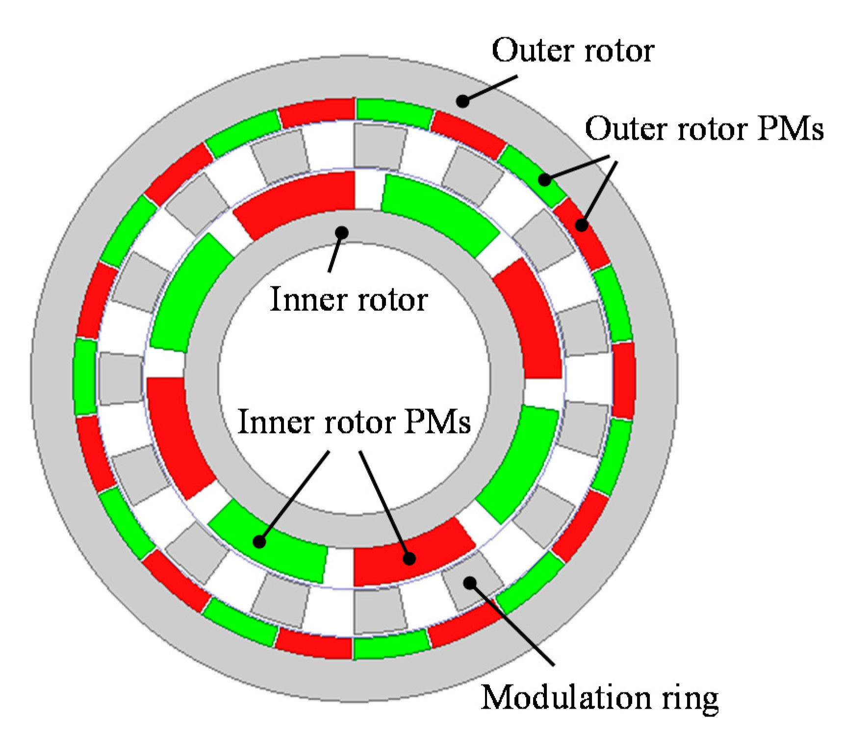
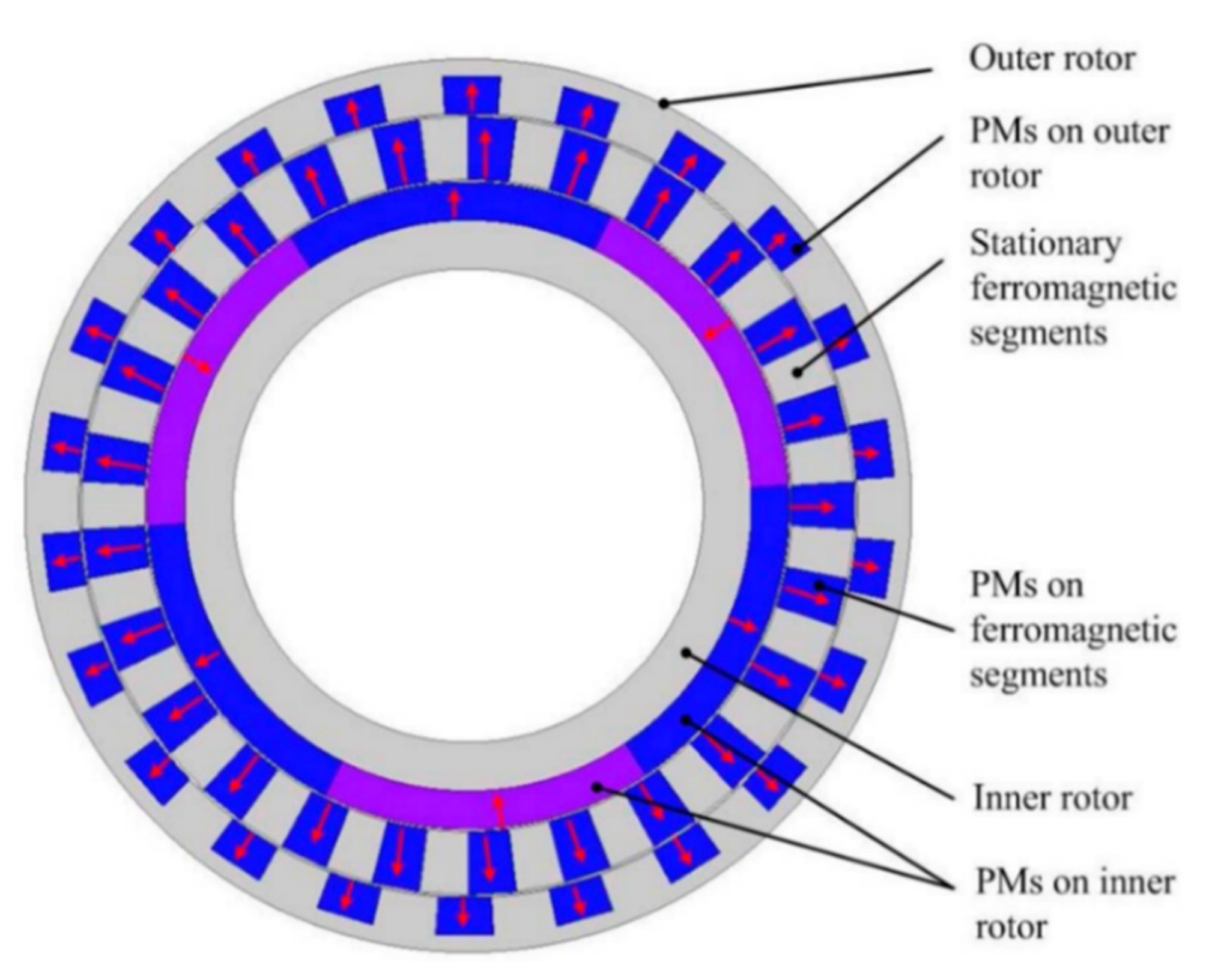
The basis of flux modulation is the permeance difference between the iron and the air, and specific harmonic components can be induced to facilitate electromagnetic torque generation. One of the famous applications of flux modulation is the magnetic gear shown in Figure 1, which has three components, an inner rotor, an outer rotor, and a modulation ring sandwiched between the two rotors [12]. The flux modulation effect caused by the permeance difference between the ferromagnetic segments and the air is the key to ensure effective coupling of the inner rotor PM field and the outer rotor PM field, and to achieve efficient torque transmission accordingly. The design principle is that the pole-pairs of the modulation ring should equal the sum of the pole-pairs of the inner rotor and the pole-pairs of the outer rotor. Any of these three components can be fixed, and the other two components can work as a magnetic gear. This magnetic gear can achieve a high torque density, 50–150 kNm/m3, and low maintenance because there is no physical contact between the input and the output.
By incorporating the magnetic gearing effect into the PM machine design, flux-modulated PM (FMPM) machines can be developed. Actually, many of the widely investigated machine concepts belong to FMPM machines, such as magnetic-geared PM (MGPM) machines, doubly salient PM (DSPM) machines, flux-switching PM (FSPM) machines, flux-reversal PM (FRPM) machines, Vernier PM (VPM) machines, etc. One common initiative of developing FMPM machines is to further increase the torque density. The incorporated gearing effect is effective in increasing rotor pole-pairs, reducing rotor speed, and amplifying output torque. The current research on FMPM machines mainly focuses on proposing novel machine concepts and developing advanced control techniques.
The purpose of this paper is to give a comprehensive review of the latest development of FMPM machines as well as provide a systematic guidance on the selection and design of FMPM machines. Based on the machine structure, the FMPM machines are grouped into four types in this paper, which are surface-type FMPM machines, spoke-type FMPM machines, partitioned stator FMPM (PS-FMPM) machines, and bidirectional FMPM machines. The working principle, advantages, disadvantages, and applications of these four types of FMPM machines are discussed from Section 2, Section 3, Section 4 and Section 5. Finally, a summary of the FMPM machines and their future developing trends are given in Section 6.
2. Surface-Type FMPM Machines
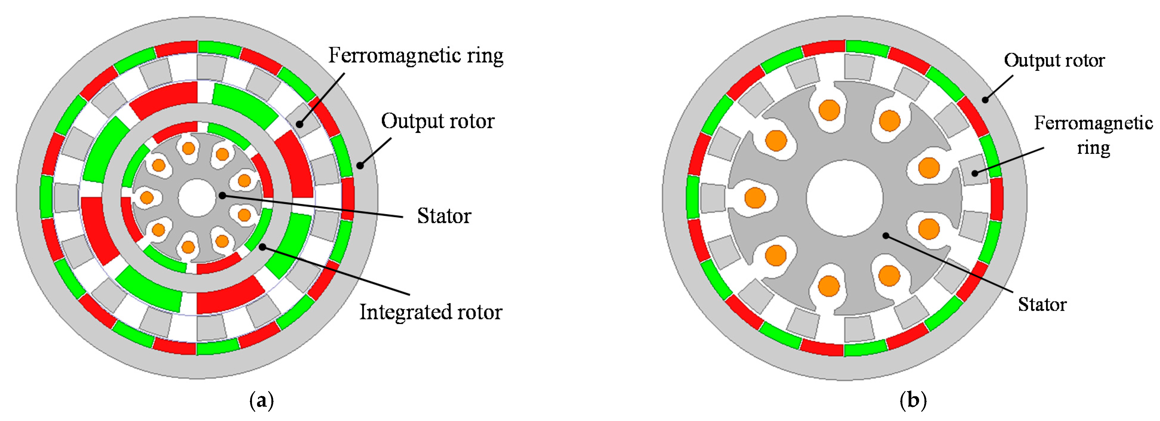
In this section, FMPM machines with the PM’s surface mounted on the rotor or the stator teeth are discussed, which are referred as surface-type FMPM machines. One typical topology of the surface-type FMPM machines is the MGPM machine shown in Figure 2a. By connecting the outer rotor of a PM machine with the inner rotor of a magnetic gear to form an integrated rotor, the output torque of the PM machine can be amplified directly by the magnetic gear, and the torque density can be as large as 87 kNm/m3, as reported in [13]. However, there are two rotating components and three air gaps in this machine, which makes the mechanical structure complicated. Manufacturing is another challenge because it is very difficult to assemble all the components accurately. If the PM machine is designed with the same pole-pairs as the inner rotor of the magnetic gear, then the magnetic fields generated by the PM machine rotor and by the inner rotor of the magnetic gear are the same; therefore, the integrated rotor can be eliminated, and the machine structure can be simplified [14], as shown in Figure 2b. In the new machine, the ferromagnetic ring is the key to ensure effective interaction between the high-speed armature field and the low-speed PM field to generate electromagnetic torque. The pole-pairs of the ferromagnetic ring are equal to the sum of the pole-pairs of the armature field and the pole-pairs of rotor, which is similar to the design principle of the magnetic gear. This machine can also be recognized as replacing the inner rotor of the magnetic gear with a machine stator.
The pseudo direct drive PM (PDD-PM) machine is another typical topology of the surface-type FMPM machines, as shown in Figure 3, in which the high-speed PM machine and the magnetic gear share a high-speed rotor [15]. The other set of PMs with large pole-pairs is surface mounted on the stator teeth, and the modulation ring acts as the output rotor. This machine can achieve a torque density higher than 60 kNm/m3 under natural air-cooling condition, and a power factor larger than 0.9 can be achieved. As a result of the contactless feature of the magnetic gear, one of the predominant features of the PDD-PM machine is the overload protection ability. When the load torque is larger than the pull-out torque, slip between the two rotors of PDD-PM machine occurs without causing serious mechanical damage. However, the slip may cause undesirable consequences such as an incorrect commutation signal, dangerous over speeding of the high-speed rotor, and loss of power transfer. A slip detection and prevention method was proposed in [16]. By detecting the slip and reconfiguring the control to maintain synchronization of the two rotors, normal operation can be swiftly resumed after overload disappears.
When the stator is designed with open slots, the stator teeth can achieve a good flux-modulating effect as the ferromagnetic segments, and a new machine concept that is referred to as a surface Vernier PM (SVPM) machine can be developed, as shown in Figure 4. Different from traditional surface-mounted PM machines with the same rotor pole-pairs and armature pole-pairs, the SVPM machine has larger rotor pole-pairs than armature pole-pairs. The stator teeth act as the flux modulators to reduce the rotating speed of the armature field and enable effective coupling between the armature field and the PM field. The design and operating principles of SVPM machine were analytically investigated using the classical permeance function in [17], and the results indicated that the SVPM machine can achieve two to three times back electromotive force (EMF) and torque of the conventional PM machine with the same volume. The influence of different pole ratios and the winding pole-pair number on the torque performance of the SVPM machine was reported in [18], and the results showed that the electromagnetic torque increases to its peak value with the increasing of the pole ratio, but it then decreases due to the large PM leakage. In low-speed applications, the rotor of the SVPM machine needs to be designed with large pole-pairs, and the stator usually has overlapping windings to achieve a low pole-pair number of an armature field with a large number of stator slots. The overlapping windings increase the length of end windings and reduce torque and efficiency accordingly. A good solution is to design the stator with auxiliary teeth, and a split-tooth SVPM machine was developed in [19], as shown in Figure 5. The auxiliary teeth act as the flux modulators, and the stator slot number can be reduced. With the same magnet usage, the split-tooth SVPM machine can achieve 20% higher torque than the regular SVPM machine. By adding a concentrated field winding into the stator slots as shown in Figure 6, the split-tooth SVPM machine can achieve hybrid excitation and DC flux weakening control [20].
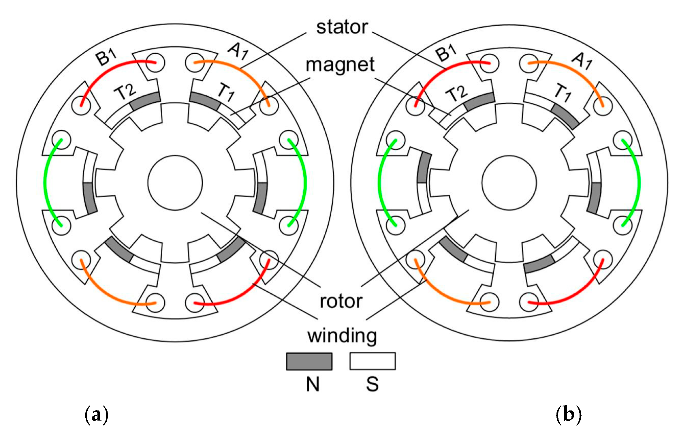
The rotors of all the aforementioned surface-type FMPM machines have PMs mounted on the surface. Since the PMs have a relatively weak mechanical strength, an additional sleeve is needed to protect the PMs from being damaged by the large centrifugal force when the rotor runs at high speeds. The protection sleeve increases the air-gap length and reduces the output torque. Flux-reversal PM (FRPM) machines are good candidates to solve this problem, which employ PMs on the surface of the stator teeth and the rotor has a robust structure with only salient poles. Considering the magnetization methods, FRPM machines can be divided into two categories, as shown in Figure 7. In Figure 7a, the magnets on the adjacent stator teeth are reversely magnetized, which is referred to as NS-SN. While in Figure 7b, the magnets on all the stator teeth are magnetized in the same way, which is referred as NS-NS. The back EMF prediction method based on air-gap field modulation theory was developed in [21]. The influence of adjacent teeth magnet polarities on the performance of FRPM machines was comprehensively investigated in [22], and the results revealed that FRPM machine with four magnet pieces mounted on each stator tooth and magnets on adjacent stator teeth that are of opposite polarities can achieve the largest output torque. Large PM leakage flux is one of the major drawbacks of FRPM machines, which causes partial magnetic saturation and results in a low power factor. An asymmetric stator pole FRPM machine was developed to reduce the leakage flux [23], whose configuration is shown in Figure 8. The asymmetric arrangement of magnets generates biased coil flux linkage, which results in torque improvement as well. The simulation and experimental results showed that this asymmetric stator pole FRPM machine can achieve 24.16% higher torque than its conventional counterpart, and a power factor of 0.76 was measured.
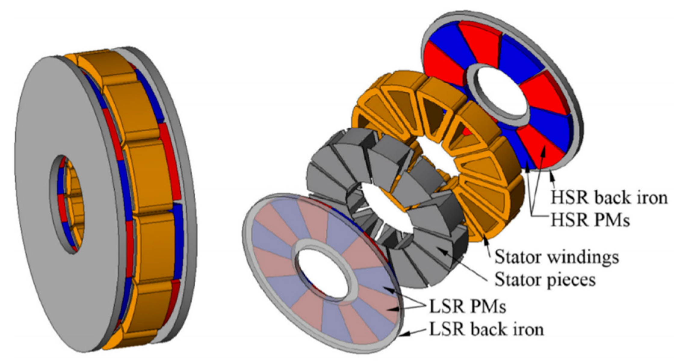
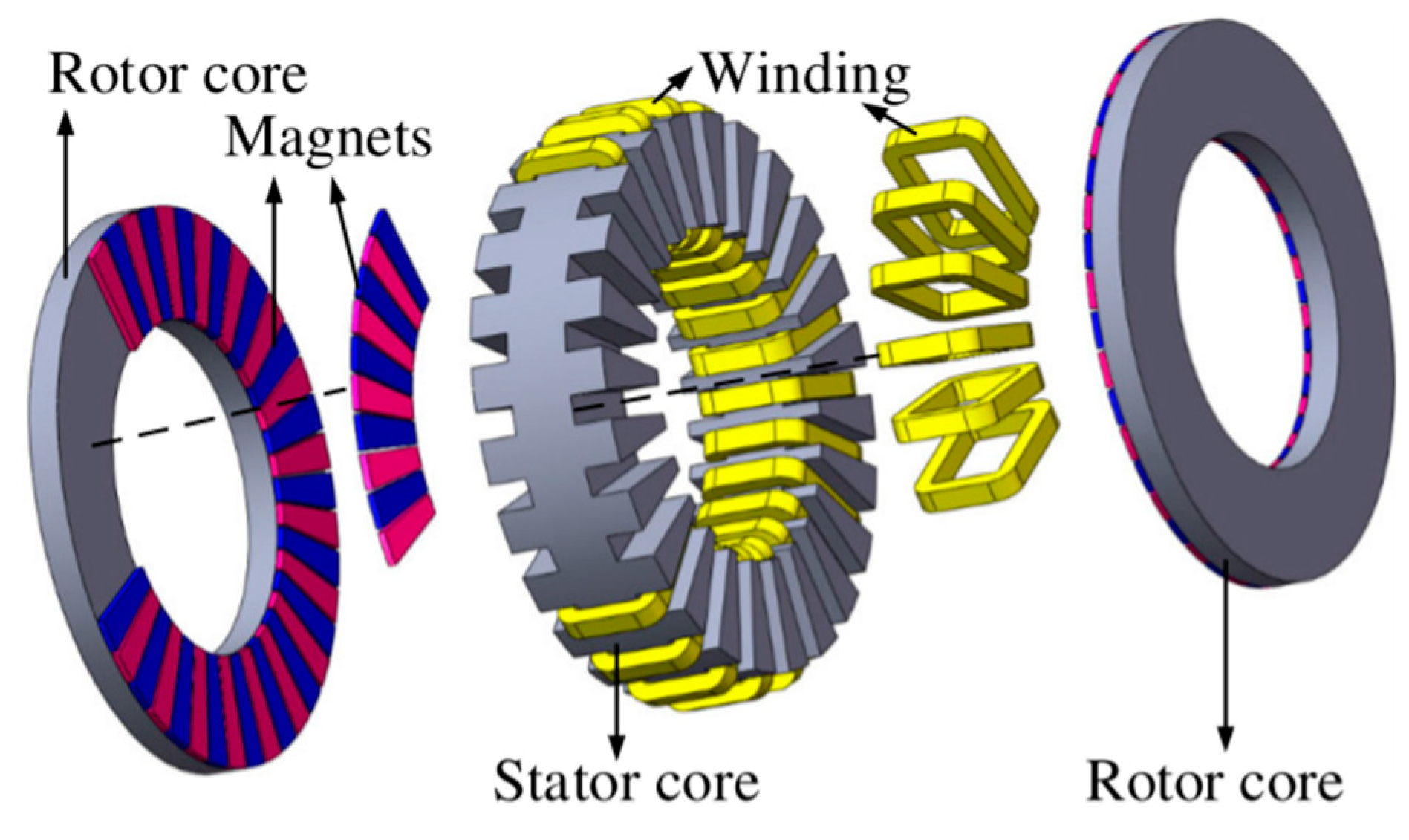
The PMs in all the aforementioned surface-type FMPM machines are radially magnetized. Actually, the surface-type FMPM machines can also be designed with axial flux, which are even more promising in achieving compact structures and high torque densities. Figure 9 shows the configuration of an axial-flux MGPM machine for power split application in hybrid electric vehicles [24], and comparative investigation showed that it can achieve significantly higher torque than the conventional axial-flux YASA machine [25]. The application of an axial-flux MGPM machine in a wind turbine was investigated in [26], and a prototype with a torque density of 7.8 kNm/m3 was designed, fabricated, and tested. A less conservative alternate design capable of achieving 60.6 kNm/m3 was also simulated to demonstrate the topology’s potential for high torque densities. An axial-flux SVPM machine was developed in [27], as shown in Figure 10. A torque density of 31.9 kNm/m3 was measured when the current density is 5.8 A/mm2, and the proposed machine is very suitable for EV/HEV propulsion because of the high torque density.
3. Spoke-Type FMPM Machines
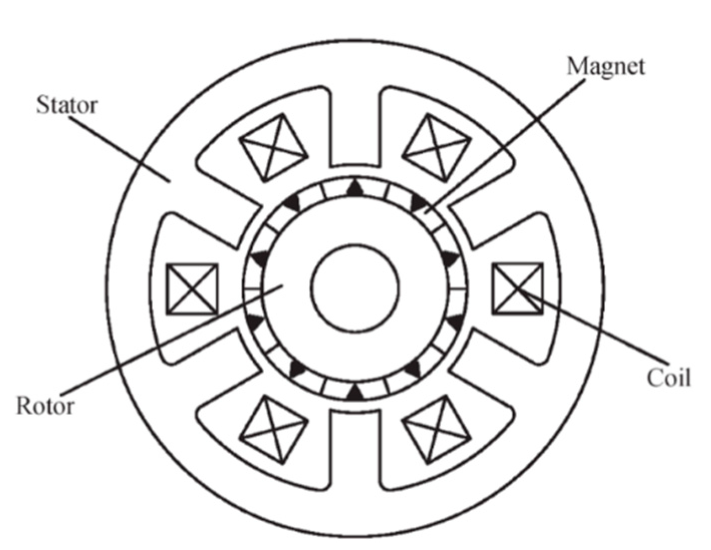
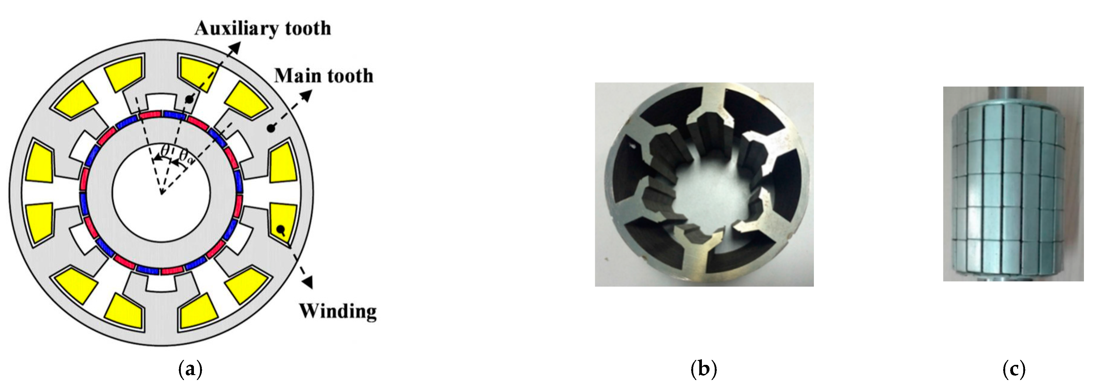
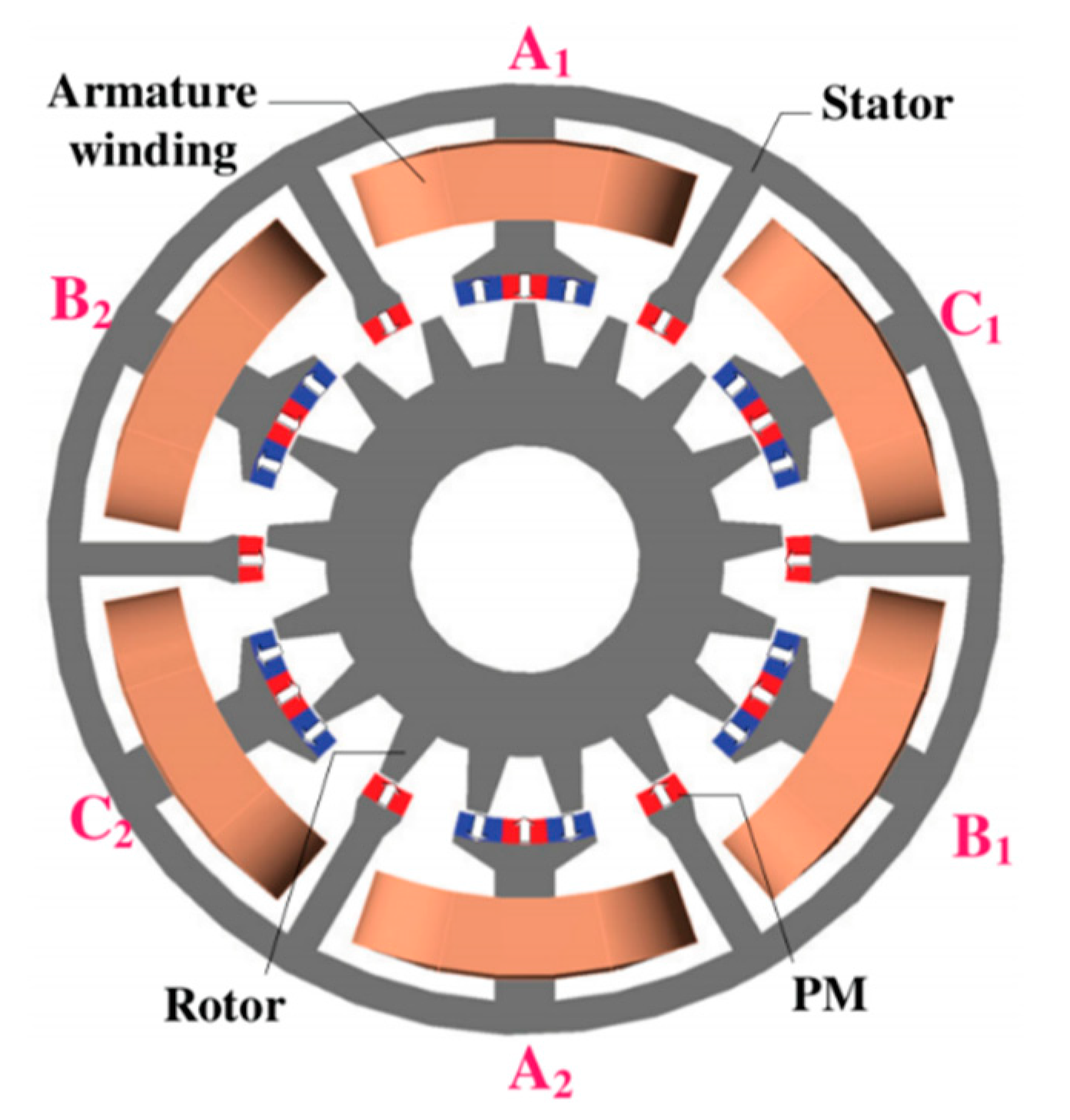
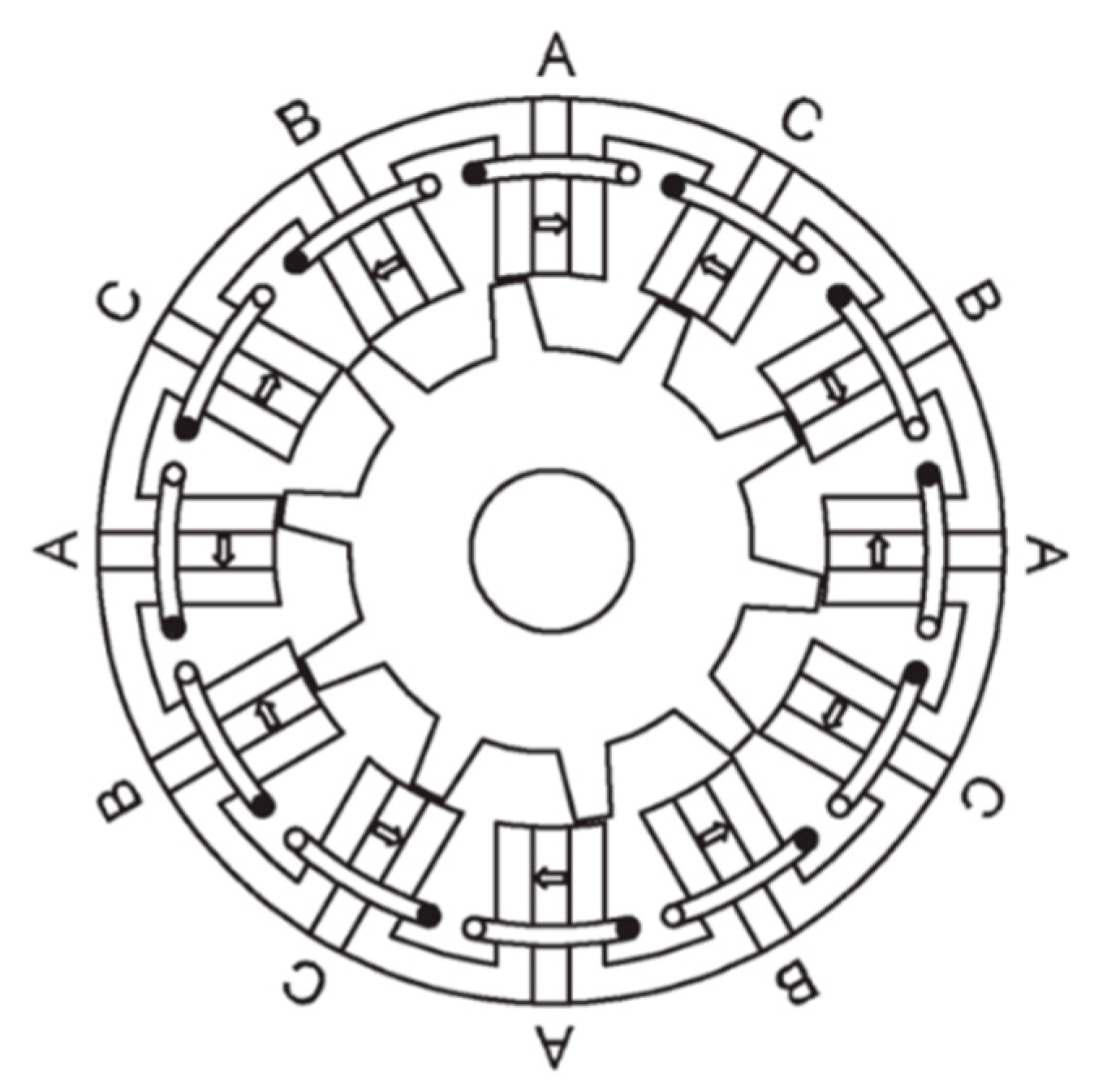
As a result of the flux focusing effect, spoke-type PM machines have been proven capable of generating higher air-gap flux density than surface-type PM machines, and they can achieve higher torque density accordingly. The employment of spoke-type PM arrays have been investigated in various PM machines, including FMPM machines. One representative spoke-type FMPM machine concept is the flux-switching PM (FSPM) machine, which has been widely investigated in recent years. The typical configuration of the FSPM machine is shown in Figure 11. The PMs are inserted into the stator teeth and the rotor only has salient poles, which is mechanically robust and suitable for high-speed applications. Since the cooling of the stator is more efficient than the cooling of the rotor, PMs in the FSPM machines have a lower risk of being demagnetized by high temperature. All the PMs are magnetized circumferentially, and the adjacent PMs are magnetized in opposite directions. The armature winding comprises concentrated coils, and each coil is being wound on a stator tooth. When the rotor rotates, bipolar flux linkage waveforms can be generated in the armature winding. The FSPM machines are promising in achieving a high torque density because of the flux focusing effect and the potential of using more PM materials. The coils can also be alternatively wound on the stator teeth, and the winding configurations and optimal stator/rotor pole combinations were investigated in [28]. An outer-rotor FSPM machine for in-wheel light traction applications was developed in [29], as shown in Figure 12. The optimal stator/rotor pole combination to maximize the back EMF and minimize cogging torque was studied, and the flux-weakening capability of the machine was analyzed and further improved by segmental PMs with iron bridges. Axial FSPM machines have also been intensively investigated for traction applications. The influence of rotor tooth shaping on the cogging torque of an axial FSPM machine was studied in [30]. A yokeless axial FSPM machine was proposed to increase the winding space and torque capability, in which the two rotors are displaced by 180 electrical degrees [31]. Compared with a conventional axial FSPM machine, this novel yokeless structure exhibits higher torque density and significantly lower cogging torque. A rotor excited axial FSPM machine was developed in [32], which demonstrates 18% higher torque density than its radial flux counterpart and is promising for EV propulsion.
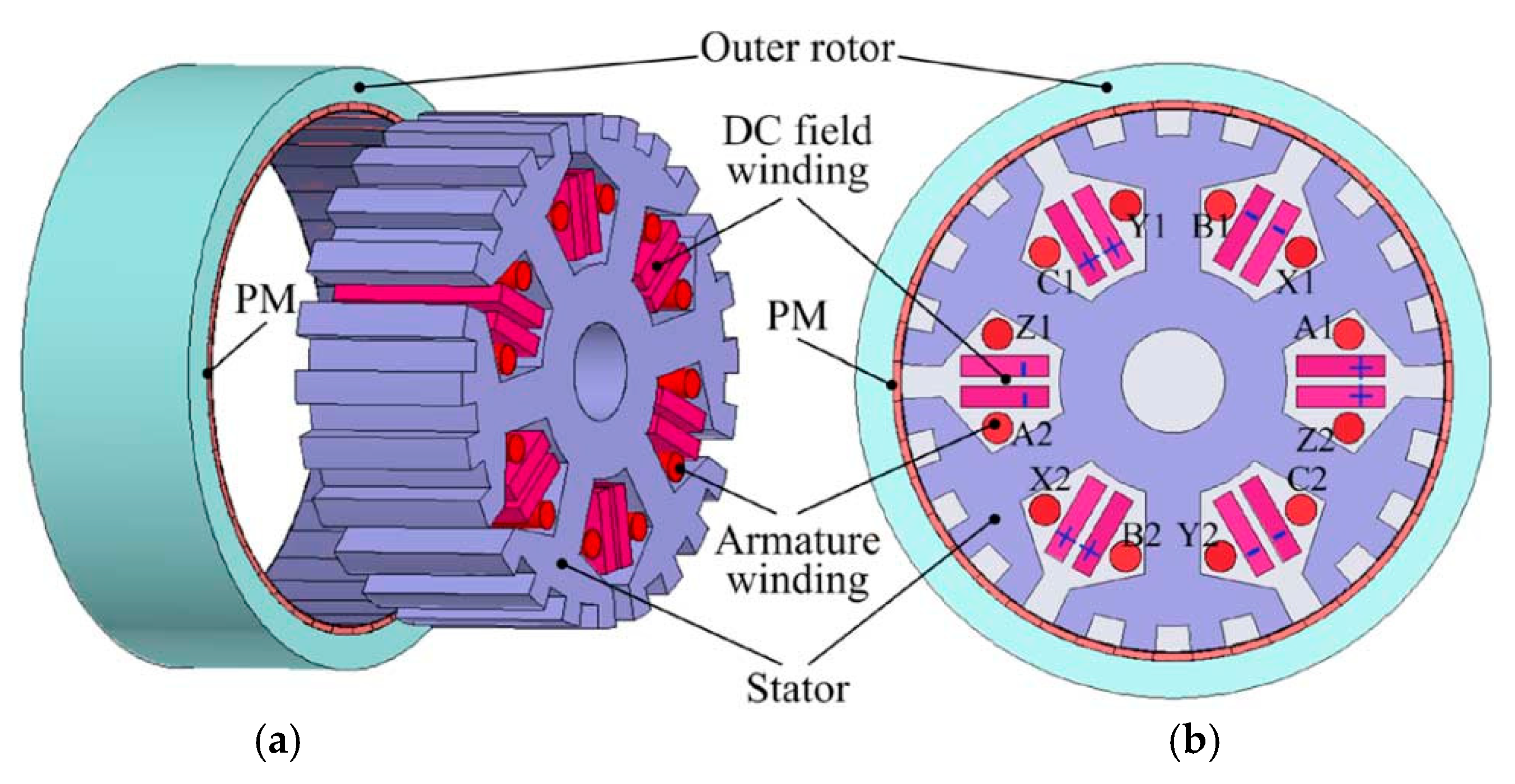
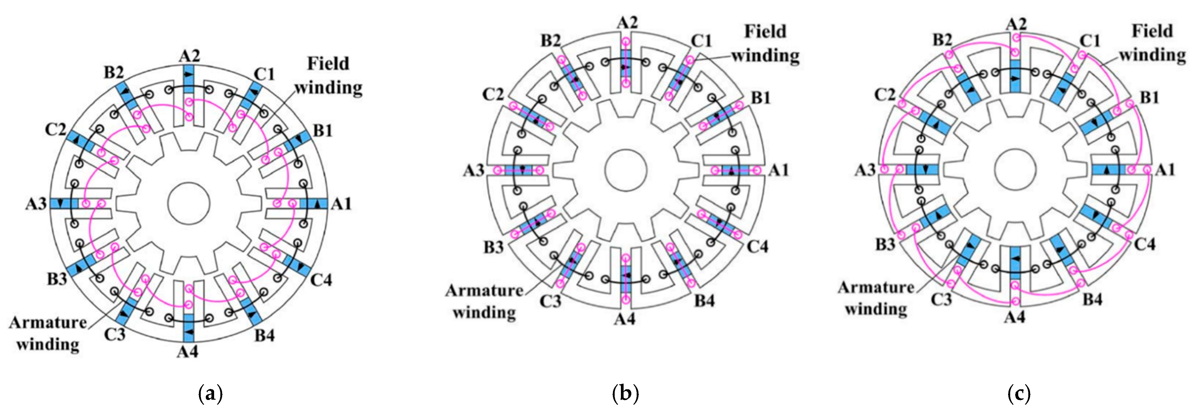
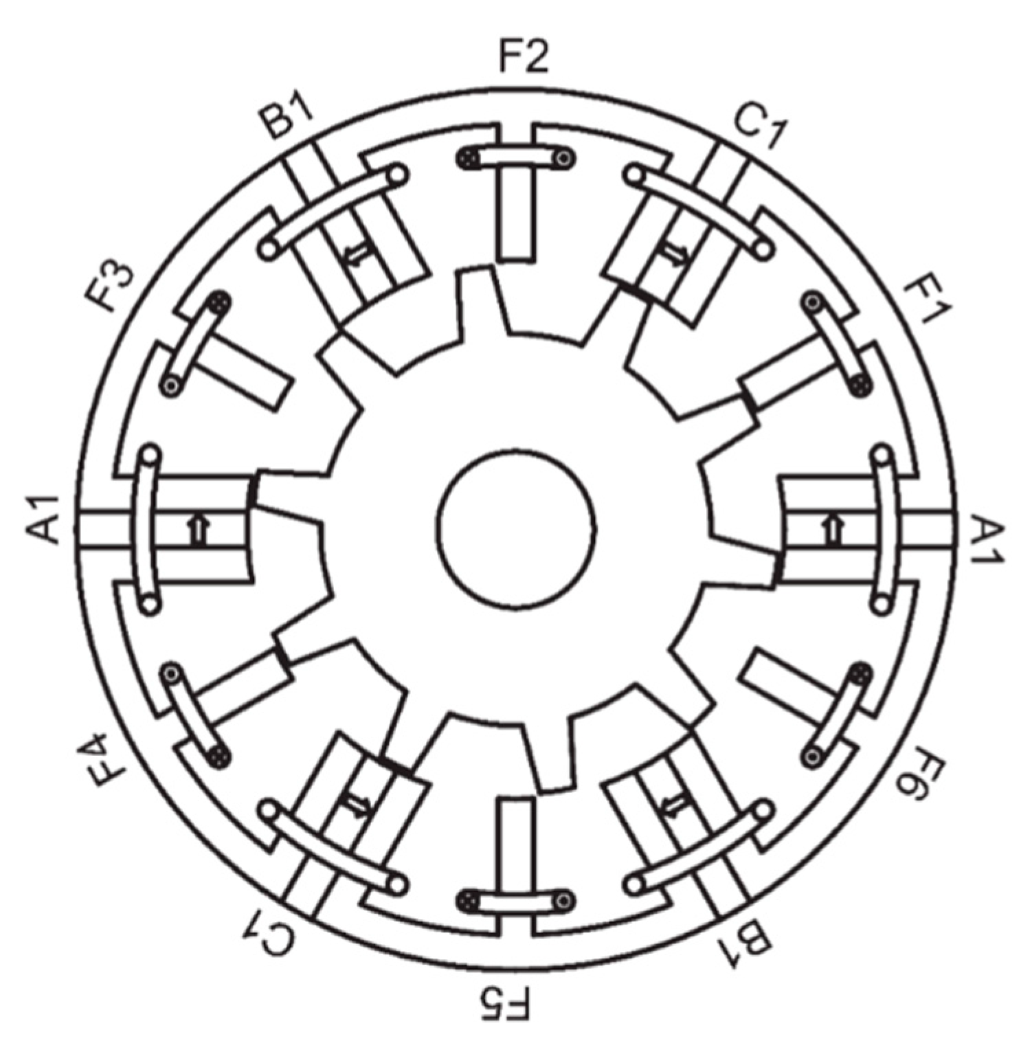
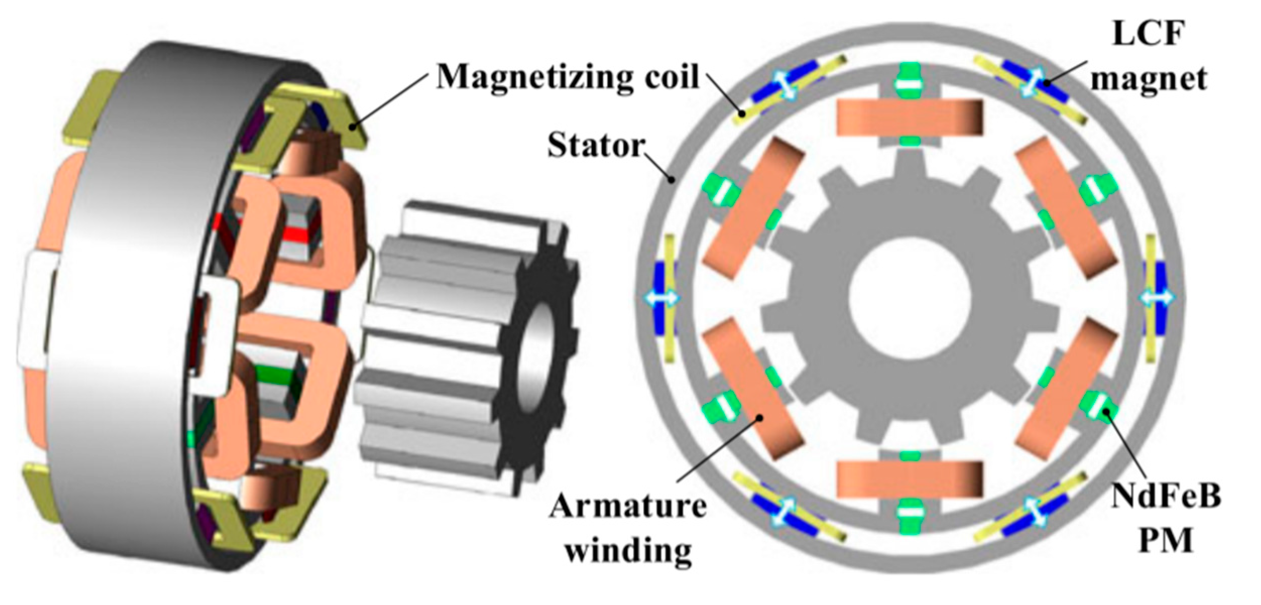
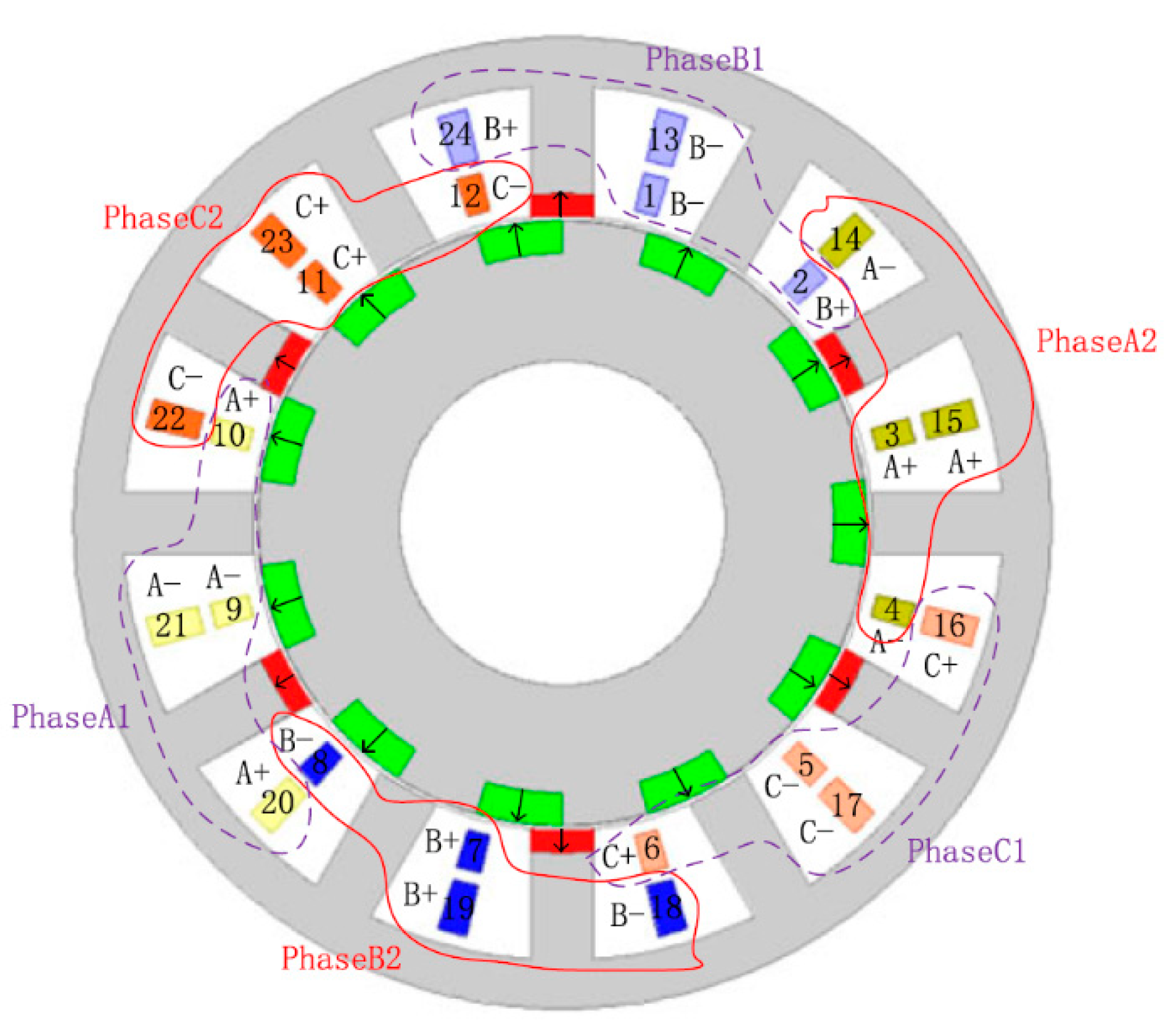
Since FSPM machines employ PMs on the stator, it is easy to realize hybrid excitation and DC flux weakening control by adding an additional field winding to the stator slots. Figure 13 shows the configurations of three different hybrid-excited FSPM machines, which have PMs at different locations of the stator teeth [34]. The flux regulation theories and principles of these three machines were analyzed, and the results showed that the PM-top machine exhibits reversal flux-regulation functions to that in the PM-bottom one. The PM-middle one can be considered as the combination of the PM-bottom machine and the PM-top machine, and it has the weakest flux-regulation capability. The effect of the field winding can be strengthened by adding an iron bridge to the outer radius of the machine, and the cost is slightly reducing the torque density [35]. The aforementioned FSPM machines have series hybrid excitation because the flux paths of the field winding and the PMs are in series, and the PMs have a risk of being demagnetized by the field current. An E-core FSPM machine was proposed to achieve parallel hybrid excitation, as shown in Figure 14, in which the PMs are safe from being demagnetized by the field current [36]. The flux-weakening capability of the E-core hybrid-excited FSPM machine can be further improved by designing the winding with five phases [37], which makes it suitable for electric vehicle propulsion. An FSPM memory machine with hybrid PMs was developed in [38], whose topology is given in Figure 15. In addition to NdFeB, low coercive force (LCF) magnets were employed on the stator. Since the working point of LCF magnets can be adjusted by applying DC current pulse, this machine can achieve flux weakening control without generating additional copper loss, and the machine can operate with high efficiency in the high-speed region.
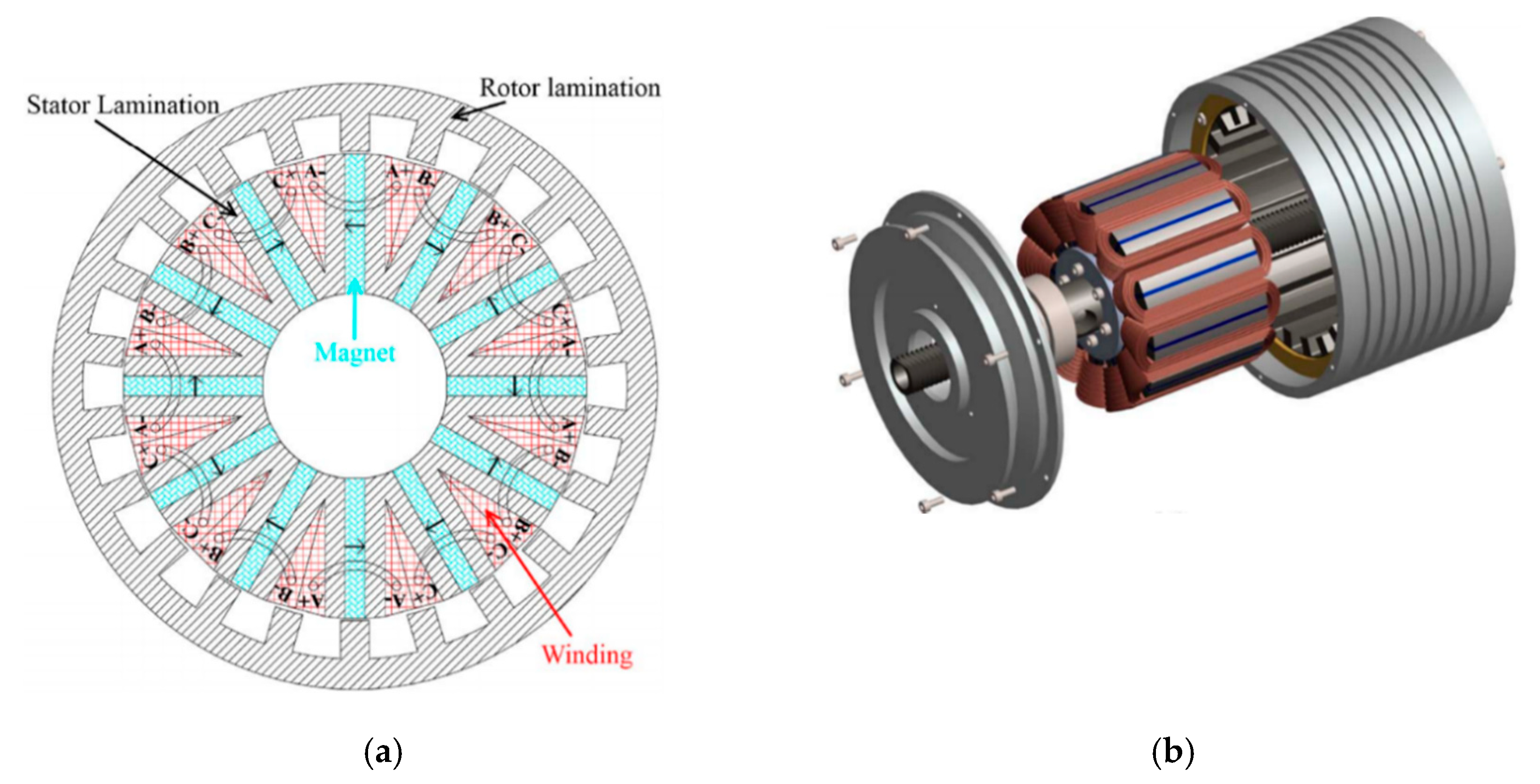
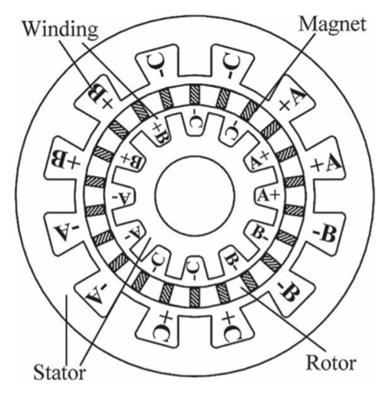
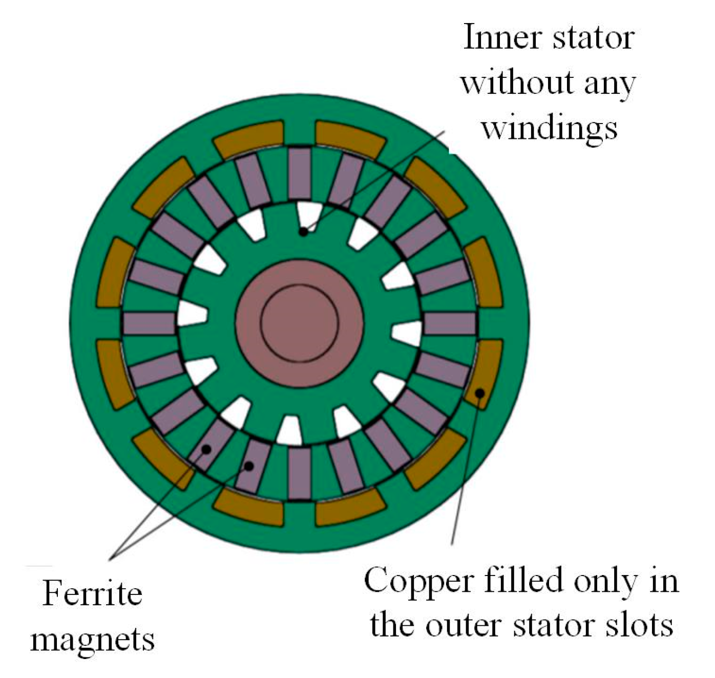
A Vernier machine is another major application of spoke-type PM array. As a result of large PM leakage flux, it is difficult for the SVPM machines discussed in Section 2 to achieve a high power factor. A good solution is to employ double stators with a half teeth pitch displacement to provide complementary flux paths [39], as shown in Figure 16. The PMs are inserted into the rotor, which are sandwiched between the two stators, and the adjacent rotor pole drives flux across the inside/outside air gap; then, the flux travels in the outside/inside stator iron and back across the air gap into the rotor. The specific relative position of the two stators and spoke PM array combine the two stators together from the view of magnetic field, and it ensures a high power factor of 0.83 according to the measurement of a prototype. The design procedure of this high-power factor VPM machine includes the design parameter initial value setting, analytical sizing equation, and key geometrical relationship formulas, and design parameter optimization was comprehensively studied in [40]. It was found that the optimal stator pole-pairs for maximum torque increase as the outer diameter increases. For a given diameter, the larger the pole ratio, the lower the optimal stator pole-pairs. The torque performance of the double stator spoke-type VPM machine was compared with an industrial interior permanent magnet (IPM) machine in [41], which showed the double stator spoke-type VPM machine demonstrates 33% higher torque production using ferrite PMs at the nominal temperature compared to that of the commercial IPM machine using rare-earth PMs. Figure 17 shows an improved structure by removing the inner stator windings [42], which eliminates the heat source inside the rotor and effectively reduces the size and weight of the inner stator.
4. Partitioned Stator FMPM Machines
Compared with rotor-PM machines, stator-PM machines have robust rotor structures and better thermal conditions. However, the compact stator structure limits the space for PMs and armature coils, and it reduces electromagnetic torque accordingly. Partitioned stator FMPM (PS-FMPM) machines were developed to boost the electromagnetic torque by employing the PMs and armature coils on two separate stators, as shown in Figure 18. This specific structure can fully utilize the space inside the machine and allows for increased copper and PM volume within the same machine volume to increase torque density. Meanwhile, the separation of PMs and armature windings allows the PMs to be cooled on a stationary body removed from the hot copper windings. Similar to the rotor of a magnetic gear, the rotor of the PS-FMPM machine is sandwiched between the two stators and comprises ferromagnetic segments. Actually, the development of PS-FMPM machines can be recognized as replacing the outer rotor of a magnetic gear with a stator. Almost all the stator-PM machines can be converted to partitioned stator types, such as doubly salient PM (DSPM) machines [43], FSPM machines [44], and FRPM machines [45]. A consequent-pole PM stator was employed in the PS-FRPM machines to save PM usage while maintaining comparable output torque and efficiency [46]. The flux-weakening control performance of PS-FSPM machines was investigated, and a novel mechanical flux-weakening technique was developed by changing the relative position of the two stators [47].
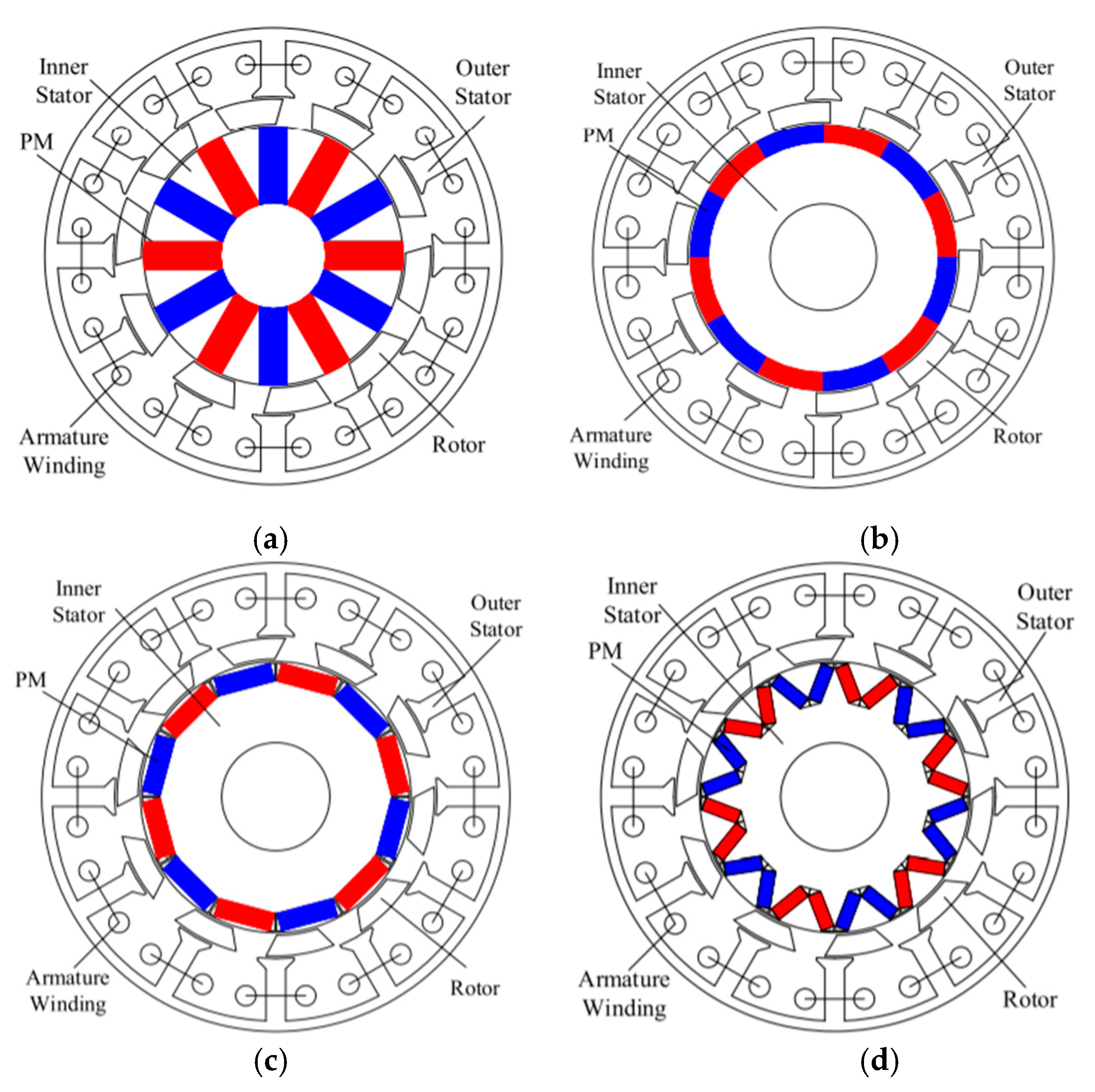
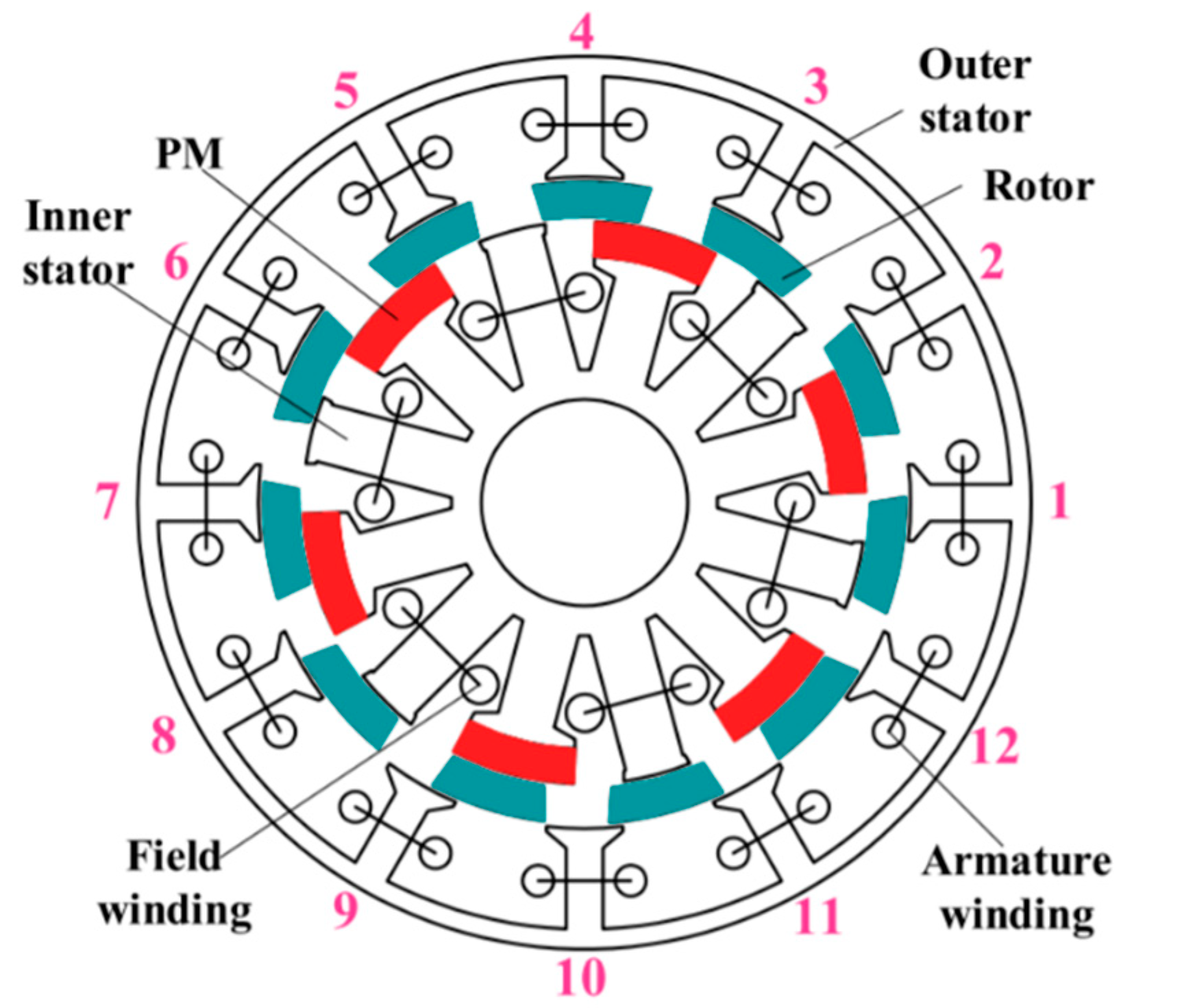
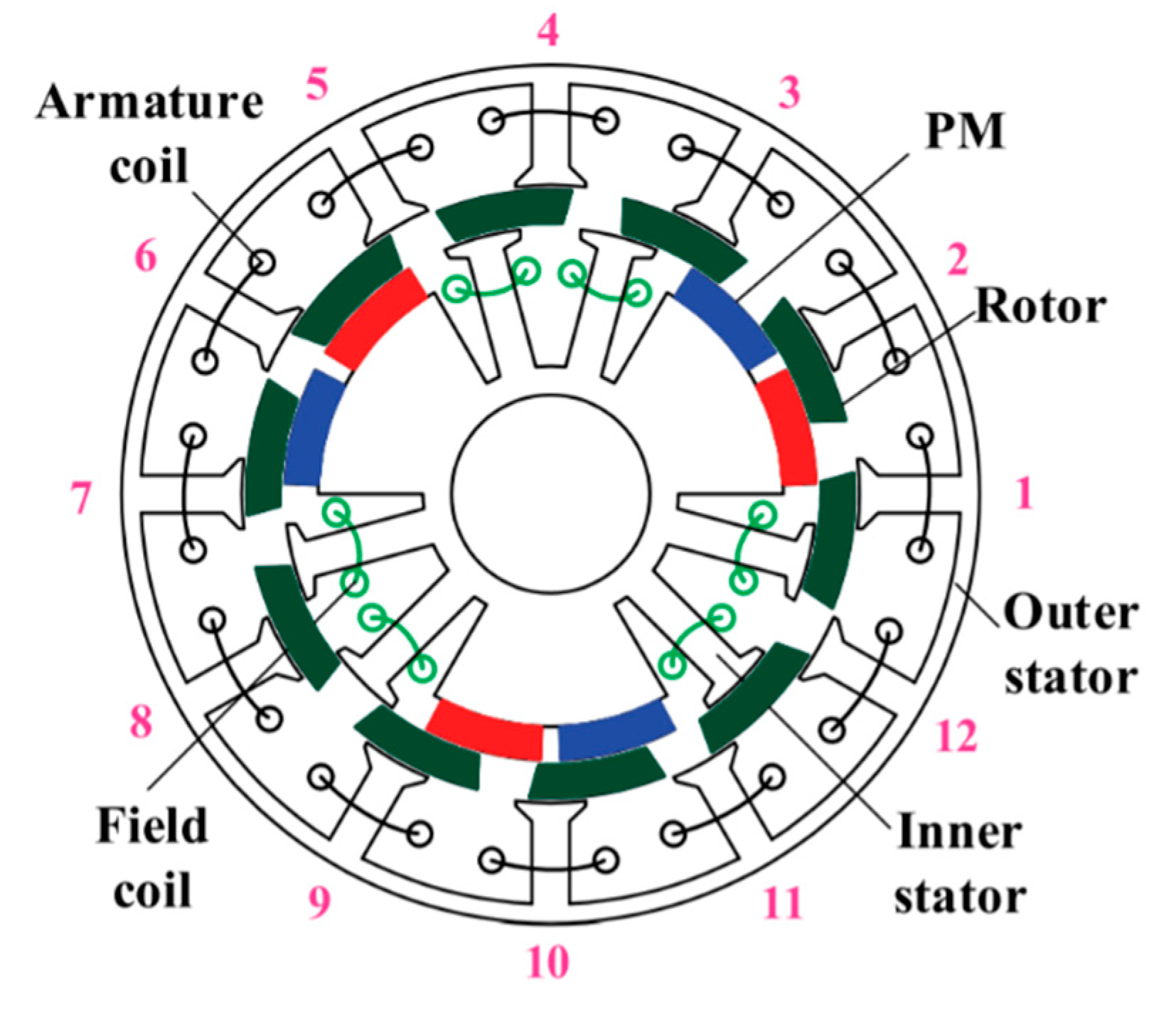
Another benefit of employing PMs on a separate stator is that it is more feasible to achieve hybrid excitation, which combines the high torque density of PM machines and excellent flux controllability of electrical-excited machines. Figure 19 shows the configuration of a series hybrid PS-FMPM machine, which has concentrated nonoverlapping field windings and PMs alternately placed on the inner stator [49]. All the surface-mounted magnets are radially magnetized with the same polarity to achieve the consequent-pole structure. By applying DC currents into the field windings, both flux enhancing and flux weakening can be realized, and the machine can maintain constant power operation over a wide speed range. Since the PMs are in series with the field winding flux, special attention should be paid to protect the PMs from being demagnetized by the field currents. An improved structure is shown in Figure 20, in which a PM pole-pair and wound field pole-pair are alternately placed on the inner stator to exhibit parallel magnetic paths [50]. This machine exhibits excellent flux regulation capability, and the PMs have very low demagnetization risk during flux weakening operation. However, the back EMF harmonics are significant because the excitation poles are not perfectly balanced. Actually, the PMs can also be installed on the slot openings [51] and yoke [52] of the inner stator, and a comprehensive summary of the PS-FMPM machines was given in [53].
5. Bidirectional FMPM Machines
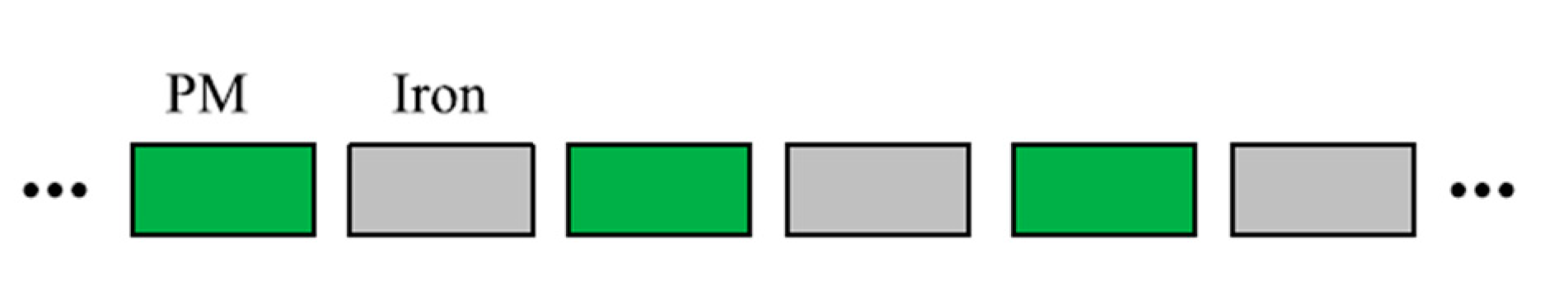
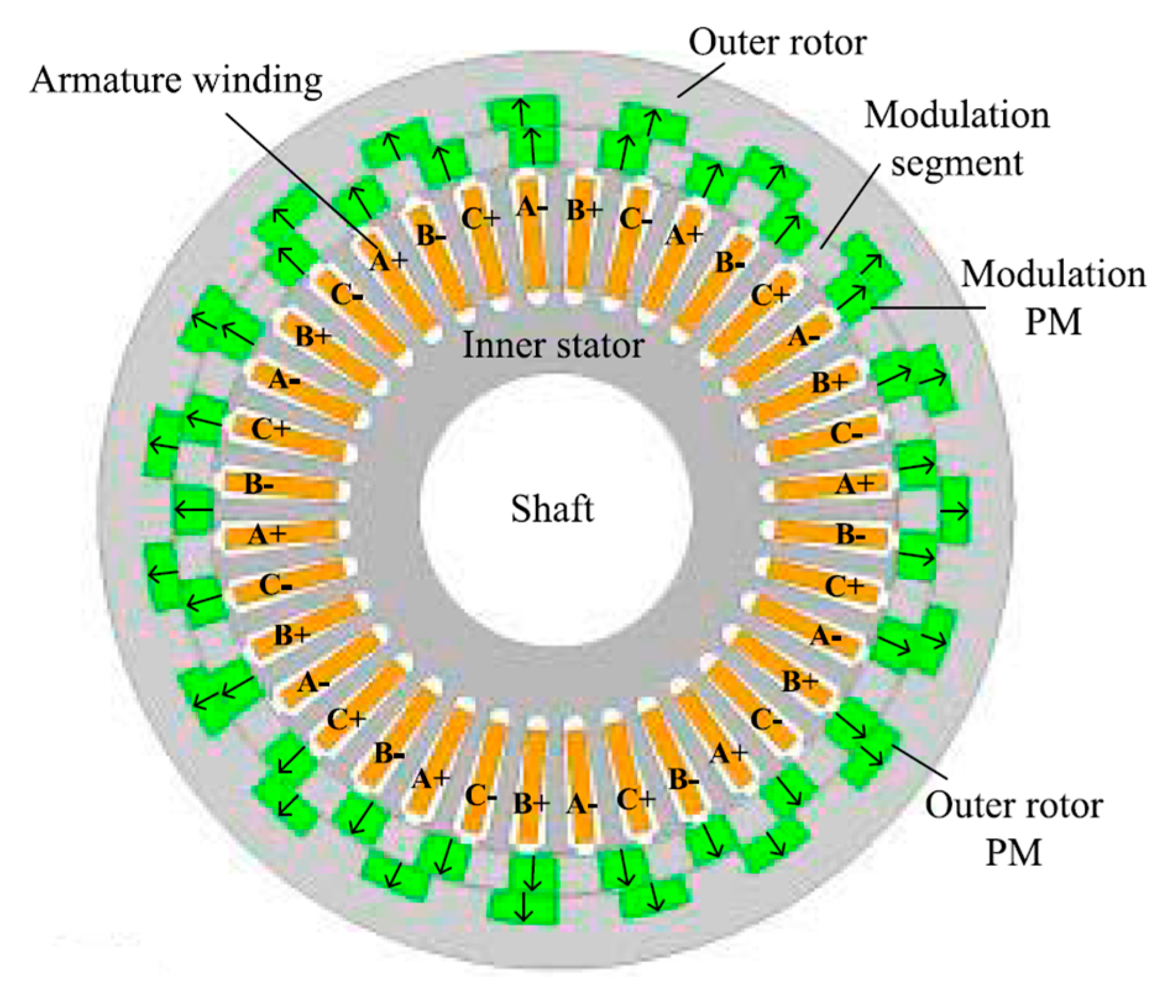
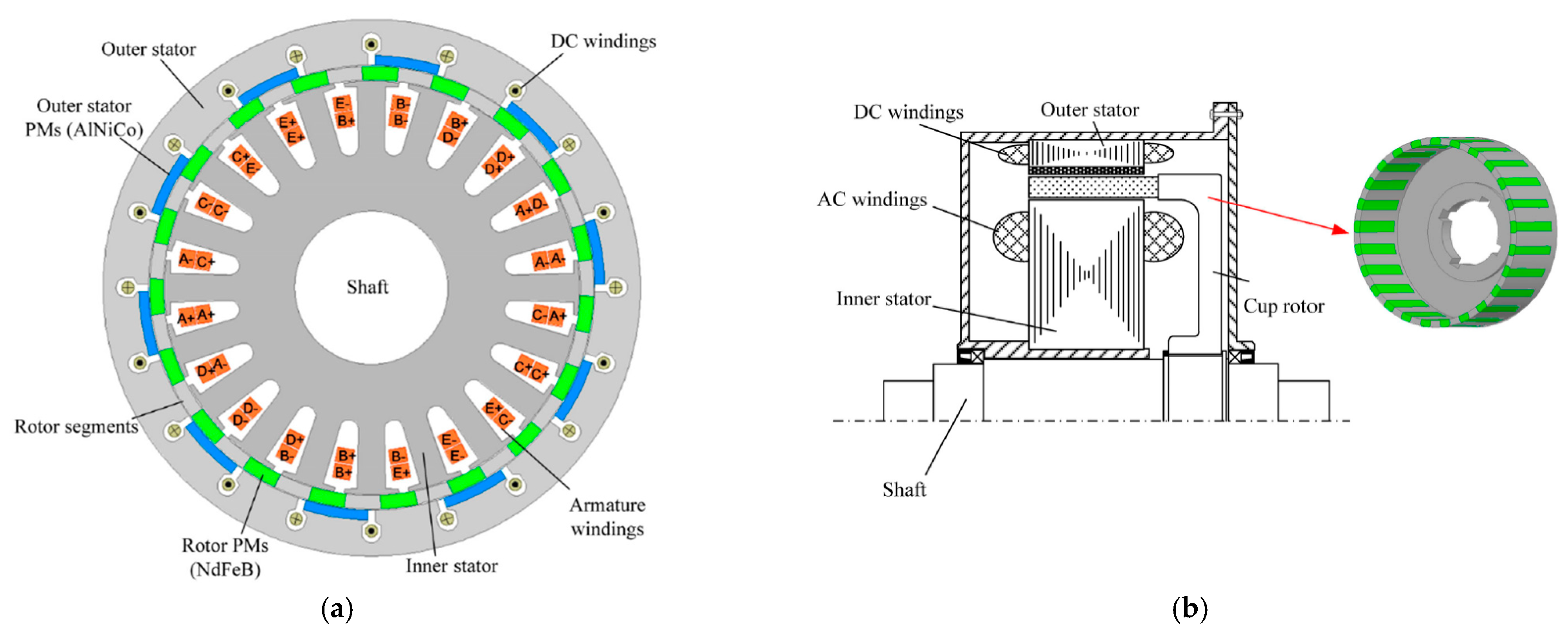
Flux modulator is the key component to achieve effective coupling between the PM excitation field and armature field in the FMPM machines, which can be a modulation ring, an open-slot stator, or a salient-pole rotor. Since the permeance of PM is close to the permeance of air, the PM–iron structure shown in Figure 21 can provide both PM excitation and flux modulation [54]. All the PMs are magnetized in the same direction—that is, radially outward/inward magnetized in rotating machines or upward/downward in linear machines. Each PM and its adjacent iron pole forms a pair of magnetic poles. It has been identified that bidirectional flux modulation can be achieved by employing a PM–iron structure on both the stator and rotor. This idea was firstly utilized on the design of a triple-PM magnetic gear [55], as shown in Figure 22, which can achieve 20% higher torque density than its counterpart shown in Figure 1. This promising technique was further implemented in the design of FMPM machines. Figure 23 shows the configuration of a bidirectional FMPM machine [56], and comparative analysis shows that it can achieve 10% higher torque than its unidirectional FMPM machine counterpart shown in Figure 2b. If the outer rotor is fixed and the modulation ring acts as the output rotor, brushless hybrid excitation can be achieved by installing an additional field winding [57]. Through utilizing hybrid PMs, NdFeB and AlNiCo, high efficiency flux-weakening operation can be achieved by injecting DC current pulse to change the working point of AlNiCo [58]. In order to improve fault tolerant capability, a five-phase bidirectional FMPM machine was developed to keep normal operation when open-circuit fault occurs [59], as shown in Figure 24.
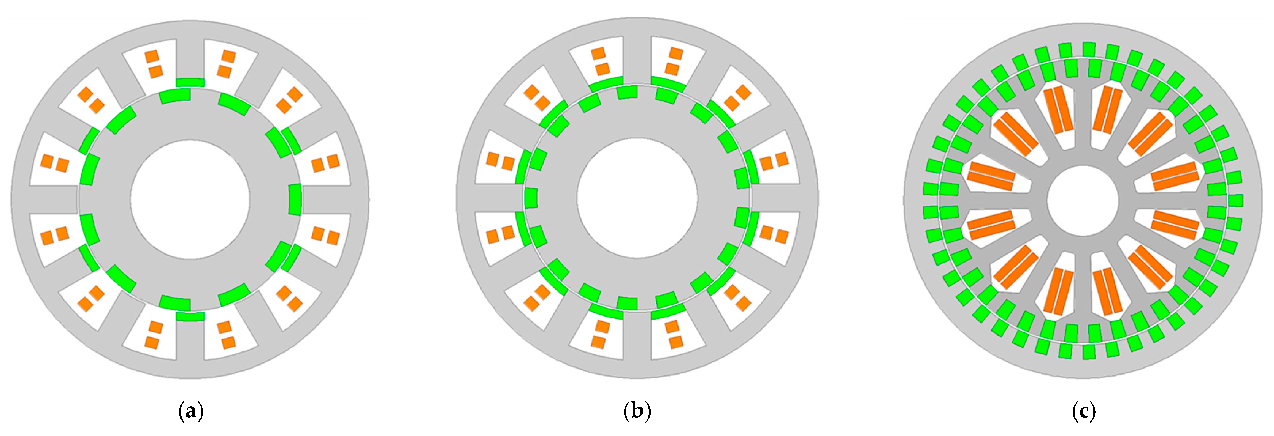
Further evolution of the bidirectional FMPM machines is realized by combining the two stators and simply the machine structure with only one air-gap. Since bidirectional FMPM machines have PMs on both the stator and the rotor, they are also referred as dual-PM machines. Figure 25 shows three typical topologies of the dual-PM machines with stator-tooth PMs, stator-slot PMs, and stator-multitooth PMs, and the rotors have the same PM–iron structure. A general design principle of the dual-PM machines was derived, and comparative study showed that the stator-tooth PM type has the lowest leakage flux and can achieve the best overall performance, such as high power factor, high efficiency, and large torque per PM volume. Similar to other machines with PMs on the stator, hybrid excitation can be achieved by adding a concentrated field winding to the stator slots, and the speed range can be expanded accordingly [60]. The common drawback of hybrid excited machines is reduced torque density, because the field winding takes up part of the slot space and reduces armature excitation. An integrated winding technique was implemented in the design of dual PM machines, as shown in Figure 26, in which armature winding and field winding are integrated, and flux regulation can be achieved by injecting DC bias current into the winding [61]. The allocation of the AC current and DC bias current can be adjusted flexibly, and the proposed machine can achieve a wide speed range without sacrificing output torque.
6. Discussion and Conclusions
FMPM machines are promising in achieving high torque density and are suitable for traction applications. The topology evolution of FMPM machines has been reviewed in this paper. According to different machine structures, FMPM machines are grouped into four categories: surface-type FMPM machines, spoke-type FMPM machines, PS-FMPM machines, and bidirectional FMPM machines. Each machine category can be designed with various topologies, and it is hard to say which one is the best. The selection of machine topology should be based on the requirements of real applications. The features of these four types of FMPM machines are summarized as follows.
- Surface-type FMPM machines have simple structures and are easy to manufacture. The PMs are glued on the surface of the rotor or the stator teeth. However, the weak mechanical strength of PMs limits the application of surface-type FMPM machines in high speeds. Meanwhile, the PMs have a demagnetization risk because the armature flux passes through the PMs.
- Spoke-type FMPM machines can achieve higher torque density than surface-type FMPM machines due to the flux-focusing effect of the spoke PM array. The drawback is a complicated mechanical structure, since the PMs have to be inserted into the stator or the rotor.
- PS-FMPM machines are good improvements on regular stator-PM machines. The separate stators not only increase the space for the installation of armature coils and PMs but also protect the PMs from being demagnetized by the hot armature coils. A tradeoff is that PS-FMPM machines have to be designed with two stators, which have higher manufacturing challenge.
- Bidirectional FMPM machines can achieve higher torque density than their unidirectional FMPM machine counterparts without increasing mechanical complexity. The PMs on the stator and the rotor can generate electromagnetic torque separately. The machine inside space can be fully utilized, and the PM arrangement is flexible.
Author Contributions
Q.W. contributed the major content of this paper. X.Z. and S.N. participated in the writing and revising of the paper. All authors have read and agreed to the published version of the manuscript.
Funding
This research received no external funding.
Conflicts of Interest
The authors declare no conflict of interest. The funders had no role in the design of the study; in the collection, analyses, or interpretation of data; in the writing of the manuscript, or in the decision to publish the results.
References
- Chau, K.T.; Chan, C.C.; Liu, C. Overview of Permanent-Magnet Brushless Drives for Electric and Hybrid Electric Vehicles. IEEE Trans. Ind. Electron. 2008, 55, 2246–2257. [Google Scholar] [CrossRef] [Green Version]
- Hyoseok, S.; Niguchi, N.; Hirata, K. Characteristic Analysis of Surface Permanent-Magnet Vernier Motor According to Pole Ratio and Winding Pole Number. IEEE Trans. Magn. 2017, 53, 1–4. [Google Scholar] [CrossRef]
- Murariu, G.; Dragu, M.; Roşu, B.; Epure, S.; Vlad, C. Updating an electric propulsion UAV device for long range missions. In Proceedings of the 2019 6th International Symposium on Electrical and Electronics Engineering (ISEEE), Galati, Romania, 18–20 October 2019; pp. 1–6. [Google Scholar]
- Barzkar, A.; Ghassemi, M. Electric Power Systems in More and All Electric Aircraft: A Review. IEEE Access 2020, 8, 169314–169332. [Google Scholar] [CrossRef]
- Nøland, J.K.; Leandro, M.; Suul, J.A.; Molinas, M. High-Power Machines and Starter-Generator Topologies for More Electric Aircraft: A Technology Outlook. IEEE Access 2020, 8, 130104–130123. [Google Scholar] [CrossRef]
- Sarlioglu, B.; Morris, C.T. More Electric Aircraft: Review, Challenges, and Opportunities for Commercial Transport Aircraft. IEEE Trans. Transp. Electrif. 2015, 1, 54–64. [Google Scholar] [CrossRef]
- Wang, Q.; Zhang, X.; Niu, S. Design of Dual-Electrical-Port DC-Coil-Free Hybrid-Excited Machines. IEEE Trans. Energy Convers. 2019, 34, 1328–1336. [Google Scholar] [CrossRef]
- Wang, Q.; Niu, S. A novel DC-coil-free hybrid-excited machine with consequent-pole PM rotor. Energies 2018, 11, 700. [Google Scholar] [CrossRef] [Green Version]
- Choi, G.; Jahns, T.M. Analysis and Design Recommendations to Mitigate Demagnetization Vulnerability in Surface PM Synchronous Machines. IEEE Trans. Ind. Appl. 2018, 54, 1292–1301. [Google Scholar] [CrossRef]
- Barcaro, M.; Bianchi, N. Interior PM Machines Using Ferrite to Replace Rare-Earth Surface PM Machines. IEEE Trans. Ind. Appl. 2014, 50, 979–985. [Google Scholar] [CrossRef]
- Ho, S.L.; Wang, Q.; Niu, S.; Fu, W.N. A Novel Magnetic-Geared Tubular Linear Machine With Halbach Permanent-Magnet Arrays for Tidal Energy Conversion. IEEE Trans. Magn. 2015, 51, 1–4. [Google Scholar] [CrossRef]
- Atallah, K.; Howe, D. A novel high-performance magnetic gear. IEEE Trans. Magn. 2001, 37, 2844–2846. [Google Scholar] [CrossRef] [Green Version]
- Jian, L.; Chau, K.T.; Jiang, J.Z. A Magnetic-Geared Outer-Rotor Permanent-Magnet Brushless Machine for Wind Power Generation. IEEE Trans. Ind. Appl. 2009, 45, 954–962. [Google Scholar] [CrossRef]
- Wang, L.L.; Shen, J.X.; Luk, P.C.K.; Fei, W.Z.; Wang, C.F.; Hao, H. Development of a Magnetic-Geared Permanent-Magnet Brushless Motor. IEEE Trans. Magn. 2009, 45, 4578–4581. [Google Scholar] [CrossRef] [Green Version]
- Atallah, K.; Rens, J.; Mezani, S.; Howe, D. A Novel “Pseudo” Direct-Drive Brushless Permanent Magnet Machine. IEEE Trans. Magn. 2008, 44, 4349–4352. [Google Scholar] [CrossRef]
- Bouheraoua, M.; Wang, J.; Atallah, K. Slip Recovery and Prevention in Pseudo Direct Drive Permanent-Magnet Machines. IEEE Trans. Ind. Appl. 2015, 51, 2291–2299. [Google Scholar] [CrossRef]
- Kim, B.; Lipo, T.A. Operation and Design Principles of a PM Vernier Motor. IEEE Trans. Ind. Appl. 2014, 50, 3656–3663. [Google Scholar] [CrossRef]
- Wu, L.; Qu, R.; Li, D.; Gao, Y. Influence of Pole Ratio and Winding Pole Numbers on Performance and Optimal Design Parameters of Surface Permanent-Magnet Vernier Machines. IEEE Trans. Ind. Appl. 2015, 51, 3707–3715. [Google Scholar] [CrossRef]
- Zou, T.; Li, D.; Qu, R.; Jiang, D.; Li, J. Advanced High Torque Density PM Vernier Machine With Multiple Working Harmonics. IEEE Trans. Ind. Appl. 2017, 53, 5295–5304. [Google Scholar] [CrossRef]
- Liu, C.; Zhong, J.; Chau, K.T. A Novel Flux-Controllable Vernier Permanent-Magnet Machine. IEEE Trans. Magn. 2011, 47, 4238–4241. [Google Scholar] [CrossRef]
- Zhu, X.; Hua, W.; Wang, W.; Huang, W. Analysis of Back-EMF in Flux-Reversal Permanent Magnet Machines by Air Gap Field Modulation Theory. IEEE Trans. Ind. Electron. 2019, 66, 3344–3355. [Google Scholar] [CrossRef]
- Yang, H.; Lin, H.; Zhu, Z.Q.; Lyu, S.; Liu, Y. Design and Analysis of Novel Asymmetric-Stator-Pole Flux Reversal PM Machine. IEEE Trans. Ind. Electron. 2020, 67, 101–114. [Google Scholar] [CrossRef] [Green Version]
- Li, H.; Zhu, Z.Q. Influence of Adjacent Teeth Magnet Polarities on the Performance of Flux Reversal Permanent Magnet Machine. IEEE Trans. Ind. Appl. 2019, 55, 354–365. [Google Scholar] [CrossRef]
- Zhu, Z.Q.; Khatab, M.F.; Li, H.; Liu, Y. A Novel Axial Flux Magnetically Geared Machine for Power Split Application. IEEE Trans. Ind. Appl. 2018, 54, 5954–5966. [Google Scholar] [CrossRef]
- Khatab, M.F.H.; Zhu, Z.Q.; Li, H.Y.; Liu, Y. Comparative study of novel axial flux magnetically geared and conventional axial flux permanent magnet machines. Ces Trans. Electr. Mach. Syst. 2018, 2, 392–398. [Google Scholar] [CrossRef]
- Johnson, M.; Gardner, M.C.; Toliyat, H.A. Design and Analysis of an Axial Flux Magnetically Geared Generator. IEEE Trans. Ind. Appl. 2017, 53, 97–105. [Google Scholar] [CrossRef]
- Zou, T.; Li, D.; Qu, R.; Li, J.; Jiang, D. Analysis of a Dual-Rotor, Toroidal-Winding, Axial-Flux Vernier Permanent Magnet Machine. IEEE Trans. Ind. Appl. 2017, 53, 1920–1930. [Google Scholar] [CrossRef]
- Chen, J.T.; Zhu, Z.Q. Winding Configurations and Optimal Stator and Rotor Pole Combination of Flux-Switching PM Brushless AC Machines. IEEE Trans. Energy Convers. 2010, 25, 293–302. [Google Scholar] [CrossRef]
- Fei, W.; Luk, P.C.K.; Shen, J.X.; Wang, Y.; Jin, M. A Novel Permanent-Magnet Flux Switching Machine With an Outer-Rotor Configuration for In-Wheel Light Traction Applications. IEEE Trans. Ind. Appl. 2012, 48, 1496–1506. [Google Scholar] [CrossRef] [Green Version]
- Kim, J.H.; Li, Y.; Cetin, E.; Sarlioglu, B. Influence of Rotor Tooth Shaping on Cogging Torque of Axial Flux-Switching Permanent Magnet Machine. IEEE Trans. Ind. Appl. 2019, 55, 1290–1298. [Google Scholar] [CrossRef]
- Fard, J.R.; Ardebili, M. Design and Control of a Novel Yokeless Axial Flux-Switching Permanent-Magnet Motor. IEEE Trans. Energy Convers. 2019, 34, 631–642. [Google Scholar] [CrossRef]
- Torkaman, H.; Ghaheri, A.; Keyhani, A. Design of Rotor Excited Axial Flux-Switching Permanent Magnet Machine. IEEE Trans. Energy Convers. 2018, 33, 1175–1183. [Google Scholar] [CrossRef]
- Chen, J.T.; Zhu, Z.Q. Comparison of All- and Alternate-Poles-Wound Flux-Switching PM Machines Having Different Stator and Rotor Pole Numbers. IEEE Trans. Ind. Appl. 2010, 46, 1406–1415. [Google Scholar] [CrossRef]
- Hua, W.; Zhang, G.; Cheng, M. Flux-Regulation Theories and Principles of Hybrid-Excited Flux-Switching Machines. IEEE Trans. Ind. Electron. 2015, 62, 5359–5369. [Google Scholar] [CrossRef]
- Owen, R.L.; Zhu, Z.Q.; Jewell, G.W. Hybrid-Excited Flux-Switching Permanent-Magnet Machines With Iron Flux Bridges. IEEE Trans. Magn. 2010, 46, 1726–1729. [Google Scholar] [CrossRef]
- Chen, J.T.; Zhu, Z.Q.; Iwasaki, S.; Deodhar, R.P. A Novel Hybrid-Excited Switched-Flux Brushless AC Machine for EV/HEV Applications. IEEE Trans. Veh. Technol. 2011, 60, 1365–1373. [Google Scholar] [CrossRef]
- Hua, W.; Su, P.; Tong, M.; Meng, J. Investigation of a Five-Phase E-Core Hybrid-Excitation Flux-Switching Machine for EV and HEV Applications. IEEE Trans. Ind. Appl. 2017, 53, 124–133. [Google Scholar] [CrossRef]
- Yang, H.; Zhu, Z.Q.; Lin, H.; Xu, P.L.; Zhan, H.L.; Fang, S.; Huang, Y. Design Synthesis of Switched Flux Hybrid-Permanent Magnet Memory Machines. IEEE Trans. Energy Convers. 2017, 32, 65–79. [Google Scholar] [CrossRef]
- Li, D.; Qu, R.; Lipo, T.A. High-Power-Factor Vernier Permanent-Magnet Machines. IEEE Trans. Ind. Appl. 2014, 50, 3664–3674. [Google Scholar] [CrossRef]
- Du, Z.S.; Lipo, T.A. Design of an Improved Dual-Stator Ferrite Magnet Vernier Machine to Replace an Industrial Rare-Earth IPM Machine. IEEE Trans. Energy Convers. 2019, 34, 2062–2069. [Google Scholar] [CrossRef]
- Li, D.; Qu, R.; Xu, W.; Li, J.; Lipo, T.A. Design Procedure of Dual-Stator Spoke-Array Vernier Permanent-Magnet Machines. IEEE Trans. Ind. Appl. 2015, 51, 2972–2983. [Google Scholar] [CrossRef]
- Du, Z.S.; Lipo, T.A. Torque Performance Comparison Between a Ferrite Magnet Vernier Motor and an Industrial Interior Permanent Magnet Machine. IEEE Trans. Ind. Appl. 2017, 53, 2088–2097. [Google Scholar] [CrossRef]
- Wu, Z.Z.; Zhu, Z.Q.; Shi, J.T. Novel Doubly Salient Permanent Magnet Machines With Partitioned Stator and Iron Pieces Rotor. IEEE Trans. Magn. 2015, 51, 1–12. [Google Scholar] [CrossRef]
- Evans, D.J.; Zhu, Z.Q. Novel Partitioned Stator Switched Flux Permanent Magnet Machines. IEEE Trans. Magn. 2015, 51, 1–14. [Google Scholar] [CrossRef]
- Zi Qiang, Z.; Zhong Ze, W.; Evans, D.J.; Wen Qiang, C. Novel Electrical Machines Having Separate PM Excitation Stator. IEEE Trans. Magn. 2015, 51, 1–9. [Google Scholar] [CrossRef]
- Wu, Z.Z.; Zhu, Z.Q. Partitioned Stator Flux Reversal Machine With Consequent-Pole PM Stator. IEEE Trans. Energy Convers. 2015, 30, 1472–1482. [Google Scholar] [CrossRef]
- Evans, D.J.; Zhu, Z.Q.; Zhan, H.L.; Wu, Z.Z.; Ge, X. Flux-Weakening Control Performance of Partitioned Stator-Switched Flux PM Machines. IEEE Trans. Ind. Appl. 2016, 52, 2350–2359. [Google Scholar] [CrossRef]
- Zhu, Z.Q.; Hua, H.; Wu, D.; Shi, J.T.; Wu, Z.Z. Comparative Study of Partitioned Stator Machines With Different PM Excitation Stators. IEEE Trans. Ind. Appl. 2016, 52, 199–208. [Google Scholar] [CrossRef]
- Hua, H.; Zhu, Z.Q.; Zhan, H. Novel Consequent-Pole Hybrid Excited Machine with Separated Excitation Stator. IEEE Trans. Ind. Electron. 2016. [Google Scholar] [CrossRef]
- Hua, H.; Zhu, Z.Q. Novel Parallel Hybrid Excited Machines With Separate Stators. IEEE Trans. Energy Convers. 2016, 31, 1212–1220. [Google Scholar] [CrossRef]
- Hua, H.; Zhu, Z.Q. Novel partitioned stator hybrid excited machines with magnets on slot openings. J. Eng. 2019, 2019, 3568–3572. [Google Scholar] [CrossRef]
- Hua, H.; Zhu, Z.Q. Novel Partitioned Stator Hybrid Excited Switched Flux Machines. IEEE Trans. Energy Convers. 2017, 32, 495–504. [Google Scholar] [CrossRef]
- Zhu, Z.Q. Overview of novel magnetically geared machines with partitioned stators. Iet Electr. Power Appl. 2018, 12, 595–604. [Google Scholar] [CrossRef]
- Wang, Q.; Niu, S.; Yang, L. Design optimization and comparative study of novel dual-PM excited machines. IEEE Trans. Ind. Electron. 2017, 64, 9924–9933. [Google Scholar] [CrossRef]
- Peng, S.; Fu, W.N.; Ho, S.L. A Novel High Torque-Density Triple-Permanent-Magnet-Excited Magnetic Gear. IEEE Trans. Magn. 2014, 50, 1–4. [Google Scholar] [CrossRef]
- Wang, Q.; Niu, S.; Yang, S. Design Optimization and Comparative Study of Novel Magnetic-Geared Permanent Magnet Machines. IEEE Trans. Magn. 2017, 53, 1–4. [Google Scholar] [CrossRef]
- Wang, Q.; Niu, S. A Novel Hybrid-Excited Flux Bidirectional Modulated Machine for Electric Vehicle Propulsion. In Proceedings of the 2016 IEEE Vehicle Power and Propulsion Conference (VPPC), Hangzhou, China, 17–20 October 2016; pp. 1–6. [Google Scholar]
- Wang, Q.; Niu, S.; Ho, S.L.; Fu, W.; Zuo, S. Design and analysis of novel magnetic flux-modulated mnemonic machines. Iet Electr. Power Appl. 2015, 9, 469–477. [Google Scholar] [CrossRef]
- Wang, Q.; Niu, S. Electromagnetic design and analysis of a novel fault-tolerant flux-modulated memory machine. Energies 2015, 8, 8069–8085. [Google Scholar] [CrossRef] [Green Version]
- Wang, Q.; Niu, S.; Luo, X. A novel hybrid dual-PM machine excited by AC with DC bias for electric vehicle propulsion. IEEE Trans. Ind. Electron. 2017, 64, 6908–6919. [Google Scholar] [CrossRef]
- Wang, Q.; Niu, S. A novel hybrid-excited dual-PM machine with bidirectional flux modulation. IEEE Trans. Energy Convers. 2017, 32, 424–435. [Google Scholar] [CrossRef]
Figure 1.
Configuration of the co-axial magnetic gear.

Figure 2.
Configurations of the magnetic-geared permanent magnet (MGPM) machines: (a) MGPM machine with three air gaps; (b) MGPM machine with two air gaps.
Figure 2.
Configurations of the magnetic-geared permanent magnet (MGPM) machines: (a) MGPM machine with three air gaps; (b) MGPM machine with two air gaps.

Figure 3.
Configuration of a pseudo direct drive PM (PDD-PM) machine [15].
Figure 3.
Configuration of a pseudo direct drive PM (PDD-PM) machine [15].

Figure 4.
Configuration of a surface Vernier PM (SVPM) machine [18].
Figure 4.
Configuration of a surface Vernier PM (SVPM) machine [18].

Figure 5.
Split-tooth SVPM machine: (a) Machine configuration; (b) Stator core; (c) PM rotor [19].
Figure 5.
Split-tooth SVPM machine: (a) Machine configuration; (b) Stator core; (c) PM rotor [19].

Figure 6.
Hybrid-excited split-tooth SVPM machine: (a) 3D structure; (b) Cross-sectional view [20].
Figure 6.
Hybrid-excited split-tooth SVPM machine: (a) 3D structure; (b) Cross-sectional view [20].

Figure 7.
Configurations of flux-reversal PM (FRPM) machines with two magnetization methods: (a) Magnets on the adjacent stator teeth that are reversely magnetized (NS-SN); (b) Magnets on all the stator teeth are magnetized in the same way (NS-NS) [21].
Figure 7.
Configurations of flux-reversal PM (FRPM) machines with two magnetization methods: (a) Magnets on the adjacent stator teeth that are reversely magnetized (NS-SN); (b) Magnets on all the stator teeth are magnetized in the same way (NS-NS) [21].

Figure 8.
Configuration of an asymmetric stator pole FRPM [23].
Figure 8.
Configuration of an asymmetric stator pole FRPM [23].

Figure 9.
Configuration of an axial-flux magnetic-geared PM (MGPM) machine [24].
Figure 9.
Configuration of an axial-flux magnetic-geared PM (MGPM) machine [24].

Figure 10.
Configuration of an axial-flux SVPM machine [27].
Figure 10.
Configuration of an axial-flux SVPM machine [27].

Figure 11.
Configuration of a flux-switching PM (FSPM) machine [33].
Figure 11.
Configuration of a flux-switching PM (FSPM) machine [33].

Figure 12.
Configuration of an outer-rotor FSPM machine: (a) Cross-sectional view; (b) Explored view [29].
Figure 12.
Configuration of an outer-rotor FSPM machine: (a) Cross-sectional view; (b) Explored view [29].

Figure 13.
Hybrid-excited FSPM machines: (a) PM-bottom; (b) PM-top; (c) PM-middle [34].
Figure 13.
Hybrid-excited FSPM machines: (a) PM-bottom; (b) PM-top; (c) PM-middle [34].

Figure 14.
Schematic of an E-core hybrid FSPM machine [36].
Figure 14.
Schematic of an E-core hybrid FSPM machine [36].

Figure 15.
Topology of a FSPM memory machine [38].
Figure 15.
Topology of a FSPM memory machine [38].

Figure 16.
Configuration of a double stator Vernier PM (VPM) machine [39].
Figure 16.
Configuration of a double stator Vernier PM (VPM) machine [39].

Figure 17.
Configuration of a double stator VPM machine without inner stator winding [42].
Figure 17.
Configuration of a double stator VPM machine without inner stator winding [42].

Figure 18.
Partitioned stator FMPM (PS-FMPM) machines: (a) Partitioned stator FSPM machine; (b) Partitioned stator FRPM machine; (c) Partitioned stator inserted IPM machine; (d) Partitioned stator V-type interior permanent magnet (IPM) machine [48].
Figure 18.
Partitioned stator FMPM (PS-FMPM) machines: (a) Partitioned stator FSPM machine; (b) Partitioned stator FRPM machine; (c) Partitioned stator inserted IPM machine; (d) Partitioned stator V-type interior permanent magnet (IPM) machine [48].

Figure 19.
Configuration of a series hybrid PS-FMPM machine [49].
Figure 19.
Configuration of a series hybrid PS-FMPM machine [49].

Figure 20.
Configuration of a parallel hybrid PS-FMPM machine [50].
Figure 20.
Configuration of a parallel hybrid PS-FMPM machine [50].

Figure 21.
Configuration of PM–iron structure [54].
Figure 21.
Configuration of PM–iron structure [54].

Figure 22.
Configuration of a triple-PM magnetic gear [55].
Figure 22.
Configuration of a triple-PM magnetic gear [55].

Figure 23.
Configuration of a bidirectional FMPM machine [56].
Figure 23.
Configuration of a bidirectional FMPM machine [56].

Figure 24.
Five-phase bidirectional FMPM memory machine: (a) Cross-sectional view; (b) Mechanical structure [59].
Figure 24.
Five-phase bidirectional FMPM memory machine: (a) Cross-sectional view; (b) Mechanical structure [59].

Figure 25.
Configurations of dual-PM machines: (a) Stator-tooth PM type; (b) Stator-slot PM type; (c) Stator-multitooth PM type [54].
Figure 25.
Configurations of dual-PM machines: (a) Stator-tooth PM type; (b) Stator-slot PM type; (c) Stator-multitooth PM type [54].

Figure 26.
Configurations of a bidirectional FMPM machine with integrated winding [61].
Figure 26.
Configurations of a bidirectional FMPM machine with integrated winding [61].

Publisher’s Note: MDPI stays neutral with regard to jurisdictional claims in published maps and institutional affiliations. |
© 2021 by the authors. Licensee MDPI, Basel, Switzerland. This article is an open access article distributed under the terms and conditions of the Creative Commons Attribution (CC BY) license (http://creativecommons.org/licenses/by/4.0/).
Share and Cite
MDPI and ACS Style
Wang, Q.; Zhao, X.; Niu, S. Flux-Modulated Permanent Magnet Machines: Challenges and Opportunities. World Electr. Veh. J. 2021, 12, 13. https://doi.org/10.3390/wevj12010013
AMA Style
Wang Q, Zhao X, Niu S. Flux-Modulated Permanent Magnet Machines: Challenges and Opportunities. World Electric Vehicle Journal. 2021; 12(1):13. https://doi.org/10.3390/wevj12010013
Chicago/Turabian StyleWang, Qingsong, Xing Zhao, and Shuangxia Niu. 2021. "Flux-Modulated Permanent Magnet Machines: Challenges and Opportunities" World Electric Vehicle Journal 12, no. 1: 13. https://doi.org/10.3390/wevj12010013