Heat Transfer Analysis of a Magneto-Bio-Fluid Transport with Variable Thermal Viscosity Through a Vertical Ciliated Channel


1
Department of Mathematics, COMSATS University Islamabad (Abbottabad Campus), Abbottabad 22060, Pakistan
2
Center of Excellence in Theoretical and Computational Science (TaCS-CoE), SCL 802 Fixed Point Laboratory, Science Laboratory Building, King Mongkut’s University of Technology Thonburi (KMUTT), 126 Pracha-Uthit Road, Bang Mod, Thrung Khru, Bangkok 10140, Thailand
3
Department of Mathematics, Abdul Wali Khan University, Mardan 23200, Pakistan
4
Department of Mathematics, Faculty of Science, King Abdulaziz University, P.O. Box 80203, Jeddah 21589, Saudi Arabia
*
Author to whom correspondence should be addressed.
Symmetry 2019, 11(10), 1240; https://doi.org/10.3390/sym11101240
Submission received: 8 September 2019
/
Revised: 27 September 2019
/
Accepted: 30 September 2019
/
Published: 4 October 2019
(This article belongs to the Special Issue Symmetry in Newtonian and Non-Newtonian Fluids)
Abstract
:We communicate the responses of various physiological fluids containing hemoglobin and other ionic constituents when they propagate in the presence of an electromagnetic body force field with the mechanisms of heat generation and conduction. A fully developed mixed convective flow of a Newtonian fluid takes place through a 2D vertical channel in the presence of an external magnetic field acting in the direction normal to the flow. The inner surface of the channel is carpeted with a thick mat of cilia, which propagates a sinusoidal metachronal wave travelling in the direction of flow. Coupled, nonlinear governing Naiver-Stokes and temperature equations are simplified by utilizing the creeping flow and long wavelength approximations. This enables us to formulate the exact analytical solution of the temperature distribution; whereas, the velocity distribution is evaluated from the momentum equations by using the Adomian decomposition method. In order to determine the pumping characteristics, the formulae of volume flow rate and the pressure rise are also obtained. Trapping due to the ciliary system is highlighted by graphing the stream function. The findings of the present model have significant outputs, which can be applicable in the physiological transport of human semen through the male reproduction system.
1. Introduction
Hair-like microscopic structures, which are recognized as cilia have featured roles in the transport processes of various physiological systems in the human bodies. The mechanical activity of cilia provides means for the locomotion of sperms and many other unicellular organisms and for the propulsion of materials and objects across the ciliated surface in multicellular animals. The role of cilia as a sensory organelle is recently admitted in addition to their capabilities in transportation, alimentation, and reproductions [1,2,3,4,5]. In the human body, cilia are found, for example, in lung trachea and bronchial tubes, where they remove mucus from the respiratory tract and the lungs; in fallopian tubes, where they support the movements of cervical mucus and the gamete cells in the oviduct; in the male reproductive system, where the cilia of ductile afferents propel sperm towards the epididymis; and in the brain as well, where the ependymal cilia facilitate the transport of cerebrospinal fluid at a small scale [6]. The structural defects in ciliary actions may cause multiple disorders affecting the functions of various organs and tissues in the body [7].
According to their roles, we can classify cilia into two groups, (i) motile cilia and (ii) non-motile cilia. The latter are also called primary cilia and perform as mechanoreceptor devices. In this study, our focus will be on the propelling features of the motile cilia, which play prominent roles in numerous physiological transport processes. In order to move fluids or objects, cilia are observed to beat in a synchronous, periodic manner and create a wave called the metachronal wave [5,6,7]. It is experimentally observed that cilia flick back and forth in an asymmetric fashion, which are classified as effective and recovery strokes. Cilia sweep a relatively larger amount of fluid volume when they bend during the effective stroke as compared to their movements during their recovery strokes. In this way, cilia create a net fluid impulsion along the forward effective stroke direction. This captivating feature of cilia motion has been now utilized in the fabrication of ciliary micro robots for drug delivery systems [8]. These above-mentioned notions of cilia have captured the attentions of many researchers during the past decade (for details see references [9,10,11,12,13,14,15,16,17,18,19]).
Heat transfer in various physiological transport processes under the impact of an external electro-magnetic field has many applications in clinical medications such as Hyperthermia therapy, Radiofrequency therapy, MRI, X-rays, thermoregulation in testis, hemodialysis, and oxygenation and in various other systems. These mechanisms have also large number of industrial applications such as in the design of magnetic artificial cilia, which can be used in nano-drug supply systems, quick disease diagnosis, and daily health monitoring. Mills et. al. [11] described that the cilia facilitate the enhancement in the heat transport effects between the walls of micro-channels whose inner surfaces are ciliated. Akbar et. al. [20] analyzed the heat transfer effects on the magnetohydrodynamics flow of a Casson fluid instigated by ciliary motion. Some more recent studies, which present the impacts of heat transfer, generation, and conduction on ciliary (as well as peristaltic) induced flows with and without magneto hydro dynamic )MHD( have been reported in references [21,22,23,24]. It is now well known that in many physiological situations, viscosity of the fluids notably changes with temperature (see [24,25,26,27,28,29,30]). For example, in thermal therapies and Hyperthermia treatments, the temperature distributions in tumors never remain uniform, i.e., the viscosity of the materials may change under high temperature differences. Therefore, dependence of viscosity on temperature in such biological processes provides a more realizable situation. Some recent studies about Newtonian and Non-Newtonian fluids with thermal behavior can be seen in [31,32,33,34,35,36,37].
Heat transmission processes is required every time there is a change in temperature amongst the boundaries or between the parts of a similar body. Heat transmission has various industrial and engineering applications, which include energy production, the transmission of heat in tissues, pasteurization process of food, fuel cells, and cooling the atomic reactor. Heat transmission is used to elucidate the performance of various systems in industrial and engineering applications. Therefore, recently numerous researchers and engineers have focused their struggle on Heat transfer problems. The recent study about heat transfer problems related with different fluids and their applications can be read in [38,39,40,41,42,43,44,45,46,47,48,49,50].
Our aim is to investigate the combined effects of heat transfer and magnetic field on the ciliary induced flows in the human body when the fluid viscosity depends upon temperature according to the Reynolds’ law of variable viscosity. The present model addresses the cilia driven transport of a magnetohydrodynamic Newtonian fluid whose viscosity depends upon temperature inside a vertical channel. The channel walls are kept at uniform temperatures and constant heat sources are present along the body force. The mathematical model of this situation will make up an important problem that can provide potential applications in bio-heat transfer and in nano-/micro-fluidic devices for drug delivery systems. We hope that this model will be helpful to understand the transport mechanisms of cilia in connection with the electromagnetic effects and heat transfer analysis of various physiological systems in the human body.
2. Statement of the Problem
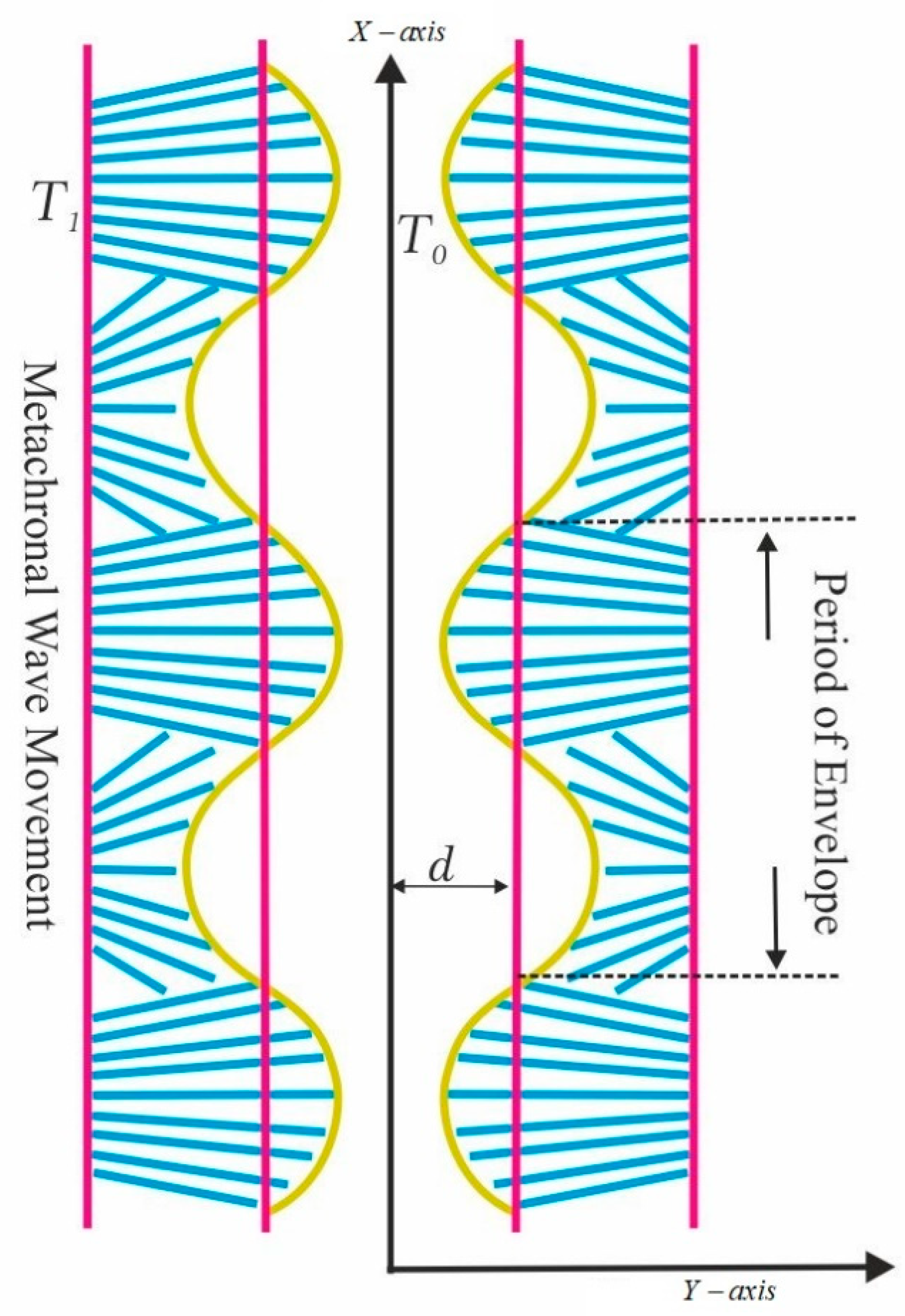
In order to describe the physical model mathematically, we designate a vertical channel of uniform width and coordinate system , in which the -axis forms the central axis of the channel and the -axis is perpendicular to it, as shown Figure 1. A fully developed mixed convective flow of an electrically conducting Newtonian fluid is occurred in this channel in the presence of an electromagnetic body force. The fluid viscosity is thermally variable and obeys the Reynolds’ law of viscosity. A ciliated epithelium covers the inner surface of the channel whose collective beatings structure a travelling wave known as metachronal wave over the ciliated surface. We delete the effects of the induced magnetic field due to a negligibly small magnetic Reynolds number. The effects of electric field are also ignored in this study, i.e., . Utilizing these constraints, the body force (Lorentz force) due to the magnetic field, , will take the form . The current density vector, , is defined as and the magnetic flux density vector is given as , where is the velocity vector and is the electrical conductivity of the fluid. The channel boundary is kept at uniform temperature , while at the centerline we use the well-known symmetry condition for temperature.
The mathematical equations for the present flow are defined as follows:
In the above mathematical model, we have employed the following two assumptions: (i) in the momentum equations, we have used the well-known Boussinesq approximation so that the density variation is detained only in the buoyancy term; and (ii) in the energy equation, we have ignored the effects of viscous dissipation. Here, represents the source term, is the variable viscosity of the fluid and the remaining terms have their well-known meanings. It is pointed out in many studies [3,9] that the beating patterns of cilia are elliptical in nature whose parametric equations are expressed mathematically as
In the above equations and , respectively, describe the positions of the ciliary paths in the horizontal and vertical directions, is the mean distance from the centerline of the channel, is the dimensionless measurement of cilia lengths, is the eccentricity measurement of the elliptical paths, is the reference position. Furthermore, is the wavelength and is the wave velocity.
With the help of Equations (5) and (6), we can determine the velocities of cilia tips along the horizontal and vertical directions as
Using Equations (5) and (6) in Equations (7) and (8) and then solving for and , we arrive at
The flow behaves as a steady state when we observe it in the wave frame attached to the metachronal wave of cilia, whereas it is unsteady in the fixed frame . These two frames are
For 2D steady flow, the velocity, pressure, and the temperature fields have the following patterns:
Also, we redefine the boundary conditions as
In order to normalize the governing equations, we allocate the following variables:
Here, (modified Reynolds number), (wave number), and (dimensionless measure with respect to the cilia length). We will now employ the above transformations along with Equations (12) and (13) into Equations (1)–(6) and then exploit the creeping flow (i.e., Re → 0) and the long wavelength (i.e., ) assumptions. Finally, the simplified system of equations we need to solve is written—after dropping the asterisks—as
The boundary conditions in dimensionless variables are manipulated as
In the above equations, (Grashof number), (Hartmann number), and (constant heat source/sink parameter). In the present investigation, we define
which reduces to the constant viscosity model when . Here, represents the viscosity variation parameter. Note that this choice of has been justified physiologically by several authors in their recent articles [25,26,27].
3. Solution Methodology
Equation (18) points out that , so we can replace with in Equation (17). The temperature field of the fluid is obtained by solving the energy Equation (19), subjected to the relevant boundary conditions on temperature as
Upon making use of Equations (22) and (23), the momentum Equation (17) will take the form
Obviously, Equation (24) does not admit an exact closed form solution. In order to solve it, we use the well-known Adomian decomposition method. Accordingly, we rewrite it in the operator form in the following way [27,28,29,30]:
where . Since is a second order differential operator, will be a twofold integral operator defined by
Applying the inverse operator , Equation (25) can be written as
In the above equation, the functions and can be formulated from the boundary conditions (20) and (21). According to the well-known Adomian decomposition method, we can write
Now, we substitute Equation (28) into Equation (27) and then decompose as
and
By utilizing the recursive relation given in Equation (30), we will compute the components , . Consequently, the three terms ADM solution for the velocity field is found to be
In the fixed frame, we construct
which can be used to define (time-mean volume flow rate) in the following way [9,12],
Upon making use of Equation (31) in Equation (32) and then solving the resultant integral, we obtain the expression for the pressure gradient as
Integrating Equation (35) over the interval , we get
which yields the expression for the pressure rise. Upon solving it for , we obtain
where , , and . The expressions for the coefficients are enlisted in Appendix A.
In order to visualize the stream line patterns of ciliary induced flow, we compute (the stream function) by introducing
into Equations (16) and (31). Here, we have used the symbolic software Maple to create the graphical representations of the streamlines, which would be helpful in analyzing the trapping phenomena in the present model.
4. Results and Discussions
This section provides physical interpretations of the graphical results computed for the velocity (), the pressure gradient (), pressure difference across one wavelength (), volume flow rate () and the 2D stream function () under changing values of the emerging parameters. These parameters are the Hartmann number (), which represents the effect of magnetic field, the viscosity variation parameter due to temperature (), which represents the fluid viscosity, the Grashof number (), which represents the buoyancy effects, and the heat source (sink) parameter (), which represents the heat transfer.
4.1. Velocity Distribution
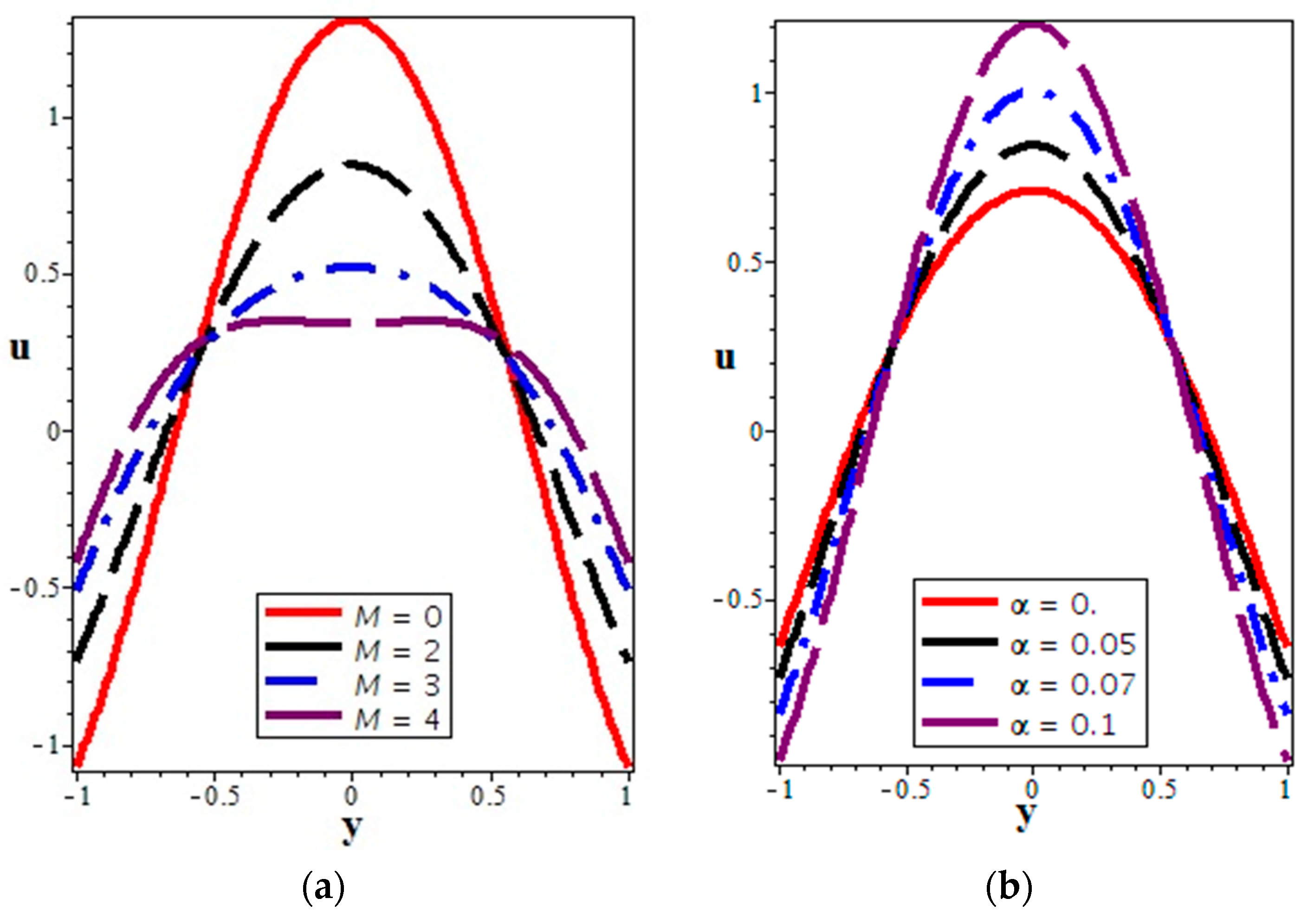
The graphs in Figure 2a represent that the fluid velocity is diminished in the central region (i.e., in the interval ) and is amplified near the channel walls. Physically, this phenomenon is associated with the magnetic body force i.e., the Lorentz force, which provides a resistance to the fluid motion [12,24]. Figure 2b shows that the fluid velocity increases with an increase in in the center of the channel, whereas it decreases slightly near the boundaries. Figure 2c,d explain that the behavior of the axial velocity is not uniform in whole region under the impacts of and . When we increase the values of the Grashof number ( is taken as negative, zero and positive) and the heat source sink parameter ( is taken as negative, zero and positive), the velocity rises in the center of the channel, whereas it decreases near the walls. The negative values in the axial velocity are noted for the negative values of the Grashof number and the heat sink parameter, which indicates the existence of flow reversal or backward flow in the human vessels.
4.2. Pressure Distribution
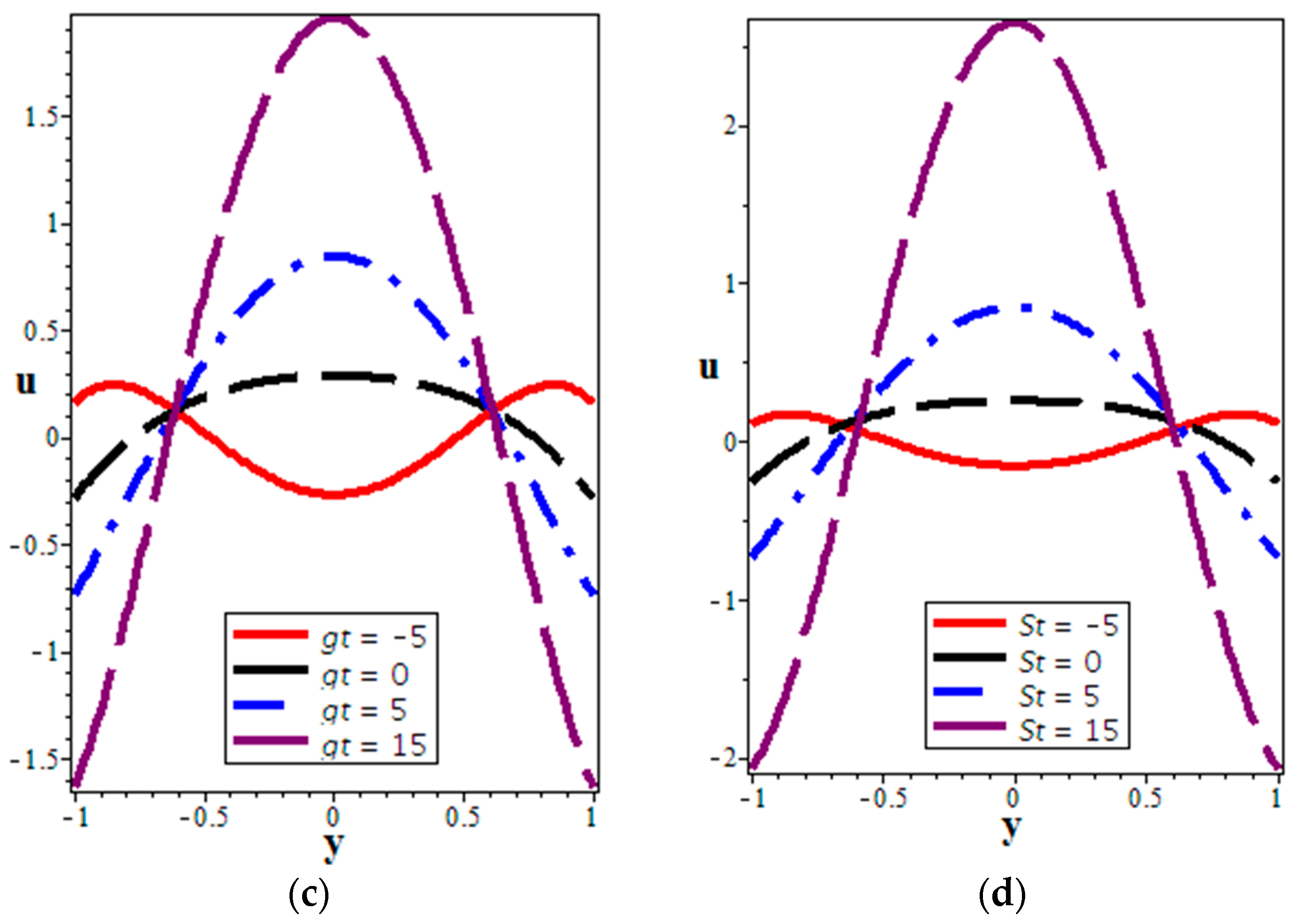
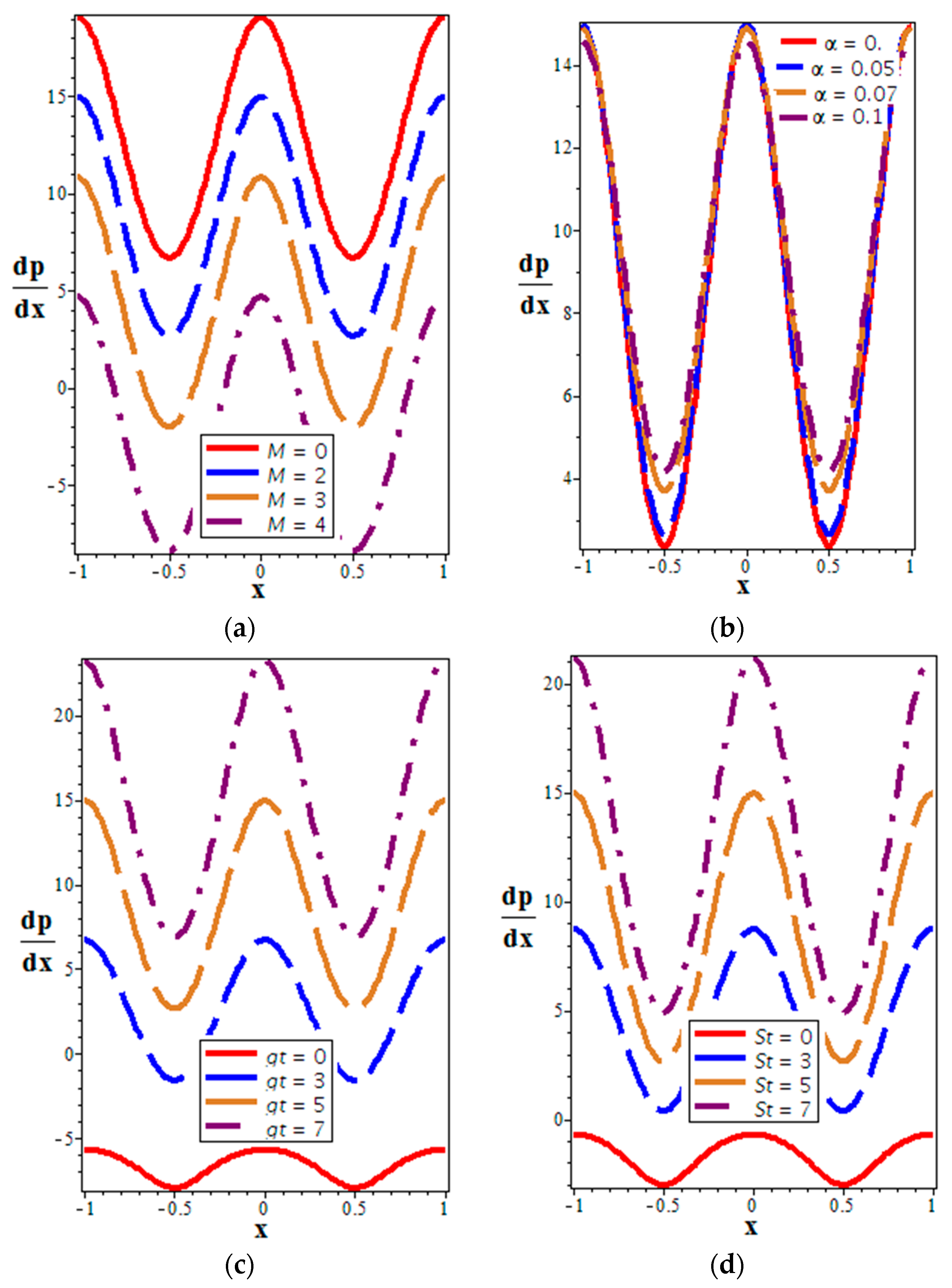
Figure 3a–d depict the behaviors of (the axial pressure gradient) versus under the effects of parameters , , , and . Figure 3a indicates that the pressure gradient is reduced when we increase the values of , i.e., the amount of the pressure gradient produced for MHD Newtonian fluid is smaller as compared to the non MHD Newtonian fluid in the channel, where they are moving. Figure 3b describes that the pressure will show non-uniform behavior over the entire region when the viscosity of the fluid depends upon its temperature, however, it may be not very significant. The graphs in Figure 3c,d indicate that there is a significant rise in when we increase the values of and . Thus, the heat transfer effect supports the development of the larger pressure gradient in the channel. These graphs clearly indicate a sinusoidal response of the pressure gradient, which endorses the correctness of our analysis.
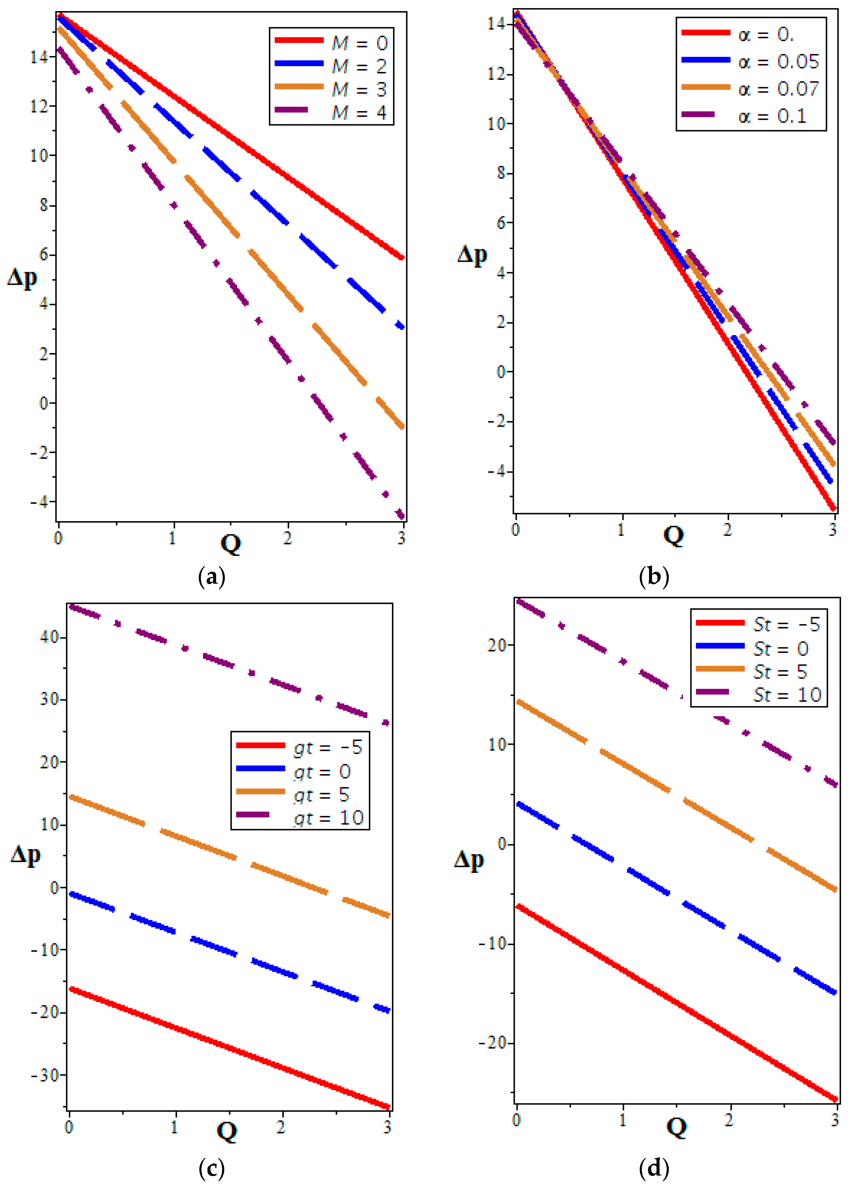
Figure 4a–d point out the variations in (the pressure difference across one wavelength) versus (the volume flow rate) for various values of , , , and . In Figure 4a, we see that the pressure difference declines significantly for higher values of the Hartmann number. This behavior highlights the pumping characteristics for MHD fluid, i.e., the pumping rate for MHD Newtonian fluid is smaller as compared to the non MHD Newtonian fluid. Figure 4b describes the effects of on versus . We note that the impacts of on substantially depend upon the amount of the flow rate. When , the effect of on the pressure difference is not much indicative. However, when , exerts potent effects on the pumping rate. Figure 4c,d explain that there is substantial growth in when we increase the values of and . Thus, the heat transfer effects promote the pumping rate.
4.3. Volume Flow Rate
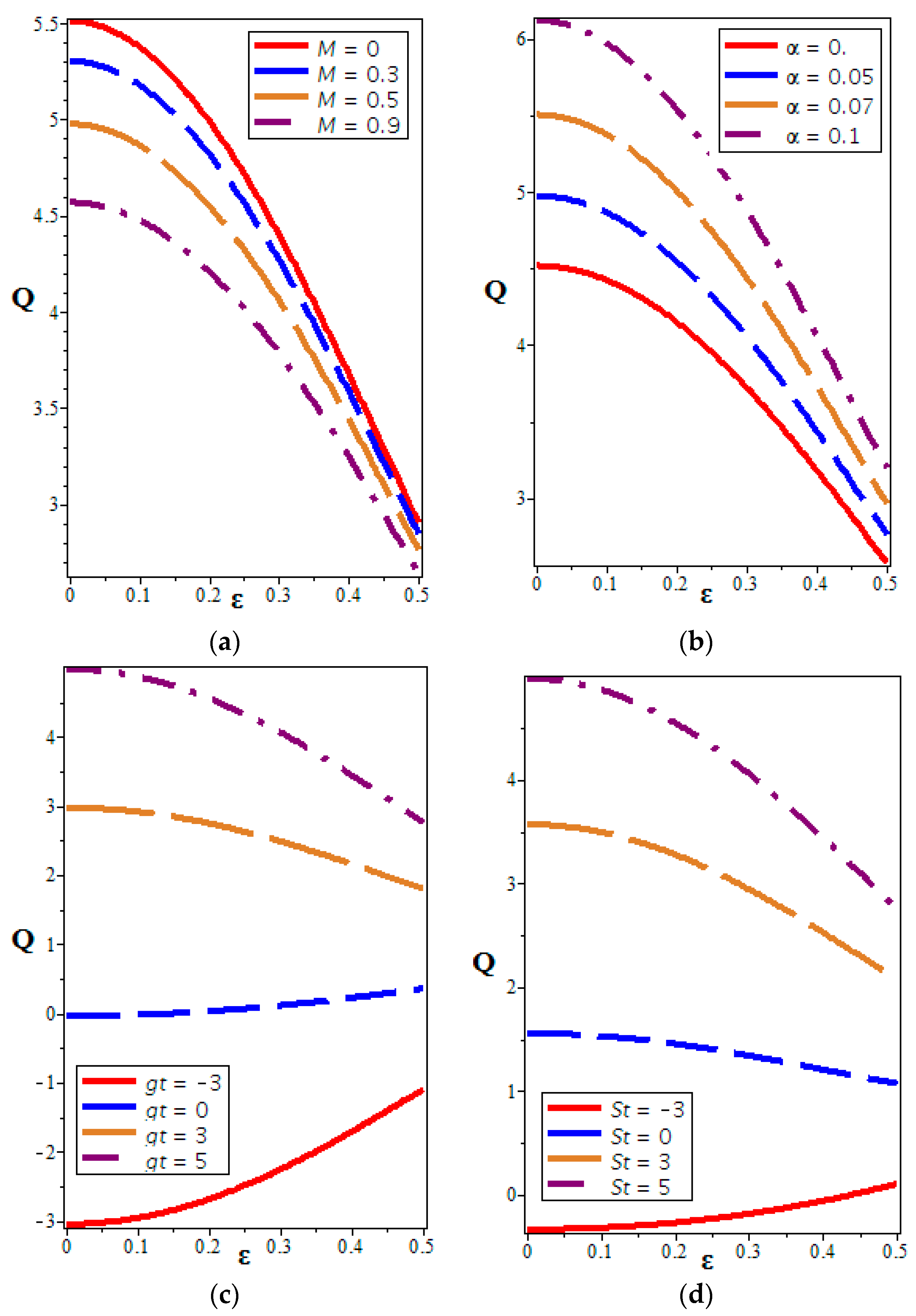
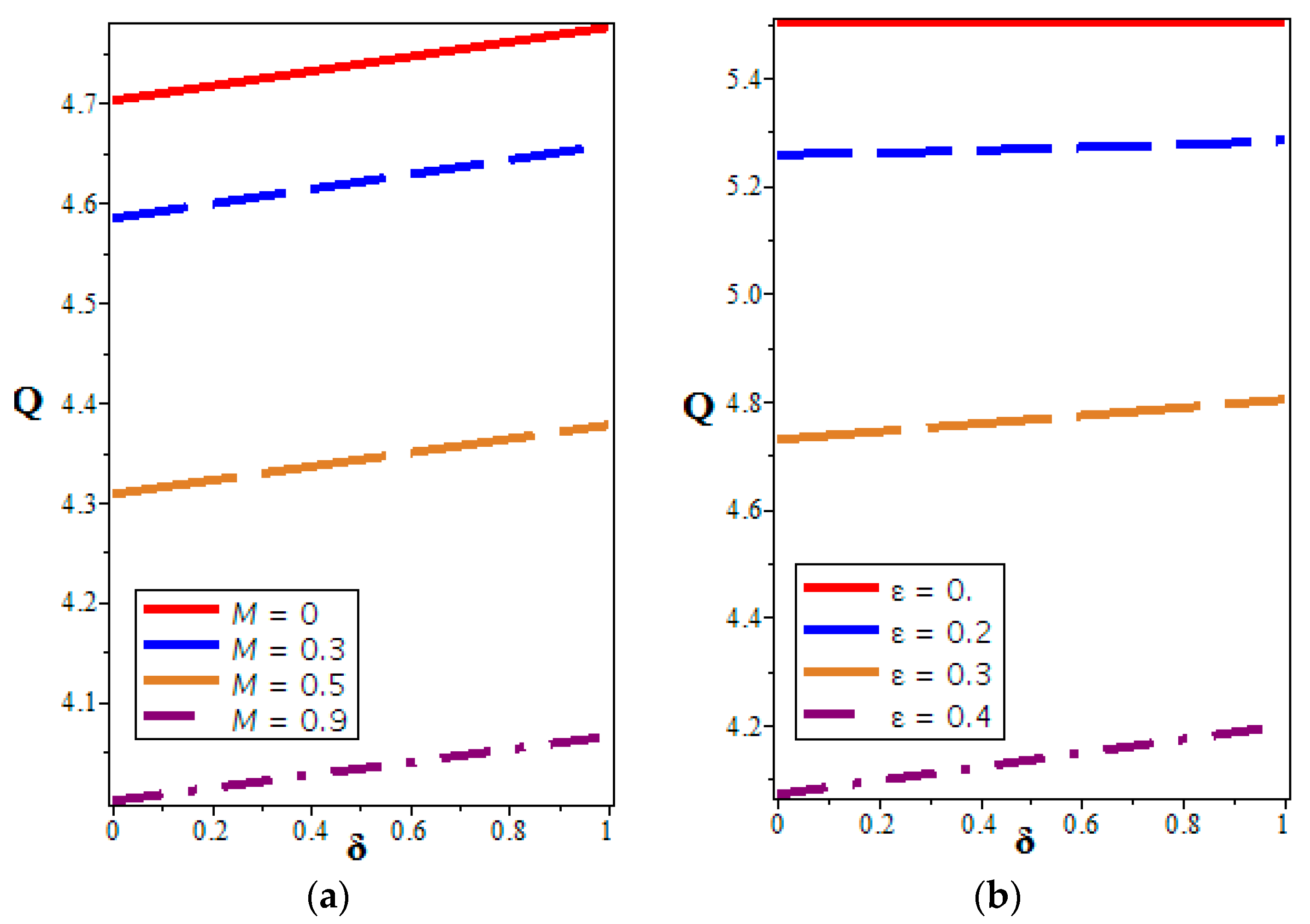
The graphs in Figure 5a depict the impacts of the Hartmann number on versus , the dimensionless cilia height estimation. Volume flow rate decreases substantially due to increasing values of the Hartmann number. From these observations, we can conclude that the presence of a magnetic field creates MHD drag force that will cause the velocity field across the channel length to decrease, and hence reduce the flow rate. This characteristic of the magnetic field has many applications in physiological flows; one of these applications is the use of magnetic field in controlling the excessive bleeding during critical surgeries. From Figure 5b, we notice that the volume flow rate for the high viscosity (temperature dependent) fluids is larger as compared to small viscosity fluids. Moreover, these graphs indicate that the cilia heights hold down the flow rate in the channel flow, i.e., they act as the controlling parameter for the fluid motion. Figure 5c,d depict that the increasing values of the thermal Grashof number and the heat source (sink) parameters produce accelerating effects on the volume flow rate. These observations endorse the actual physical situations and are according to the results of previous studies mentioned in the literature [24,25,26,27,28,29,30]. Furthermore, it can be seen that the variation in the flow rate is not same for negative values of and as compared to their positive values, i.e., the flow rate increases with the cilia heights when we take negative values of these parameters. Thus, the heat transfer effects support the volumetric flux in the physiological conduits. Figure 6a,b describe the impacts of (Hartmann number) and (the cilia length parameter) on (the volume flow rate) versus (the eccentricity parameter). We note that the volume flow rate decreases with the Hartmann number and the cilia heights, whereas it increases with the eccentricity parameter.
4.4. Trapping Phenomenon
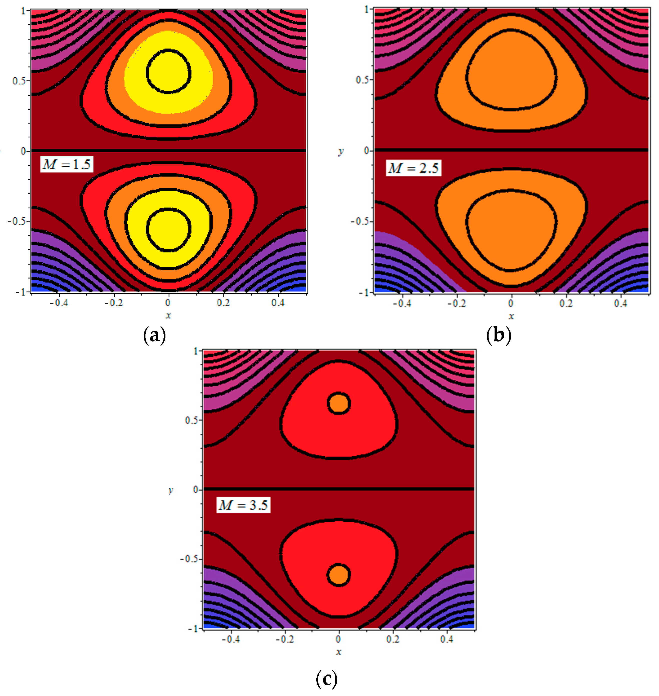
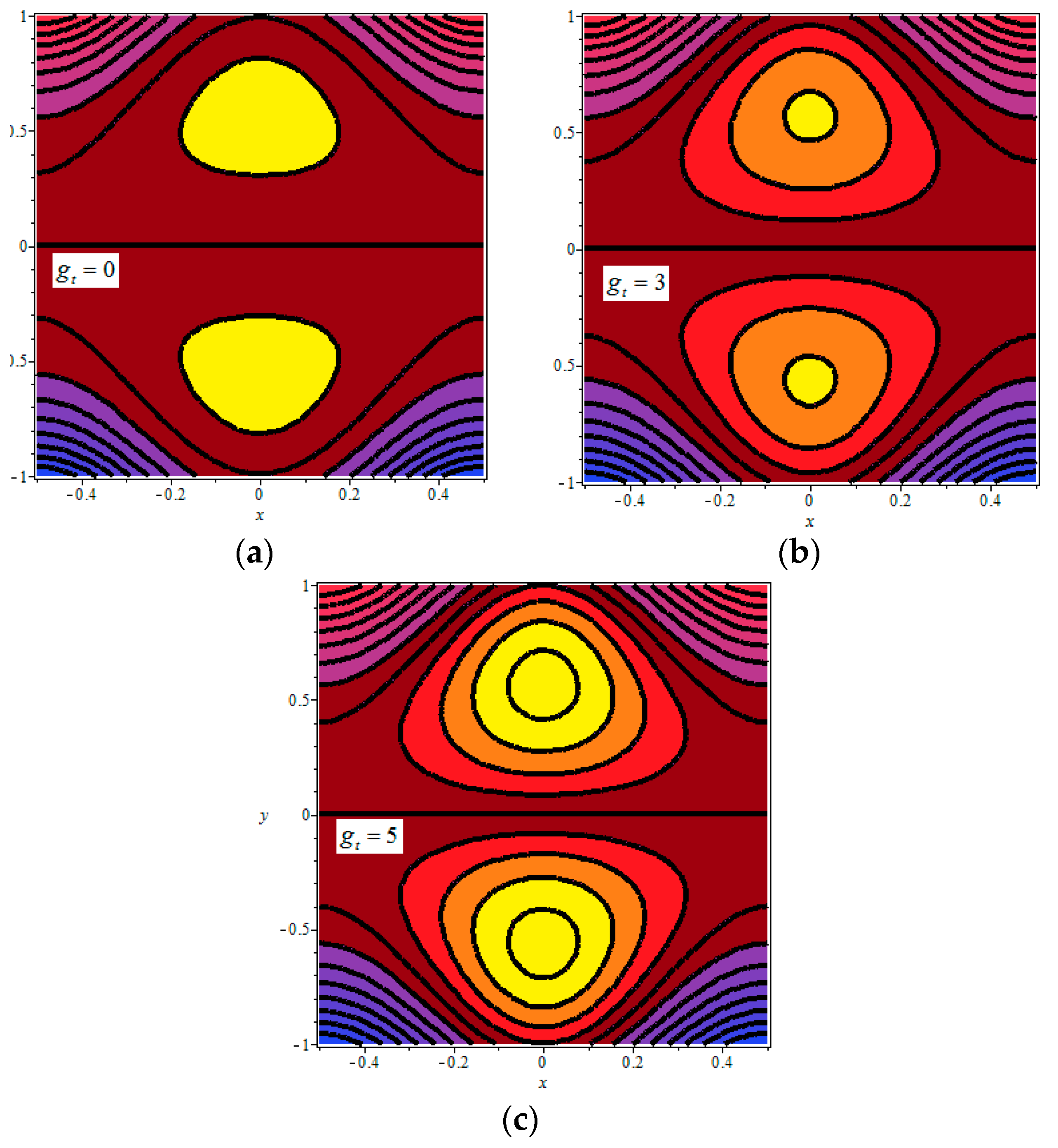
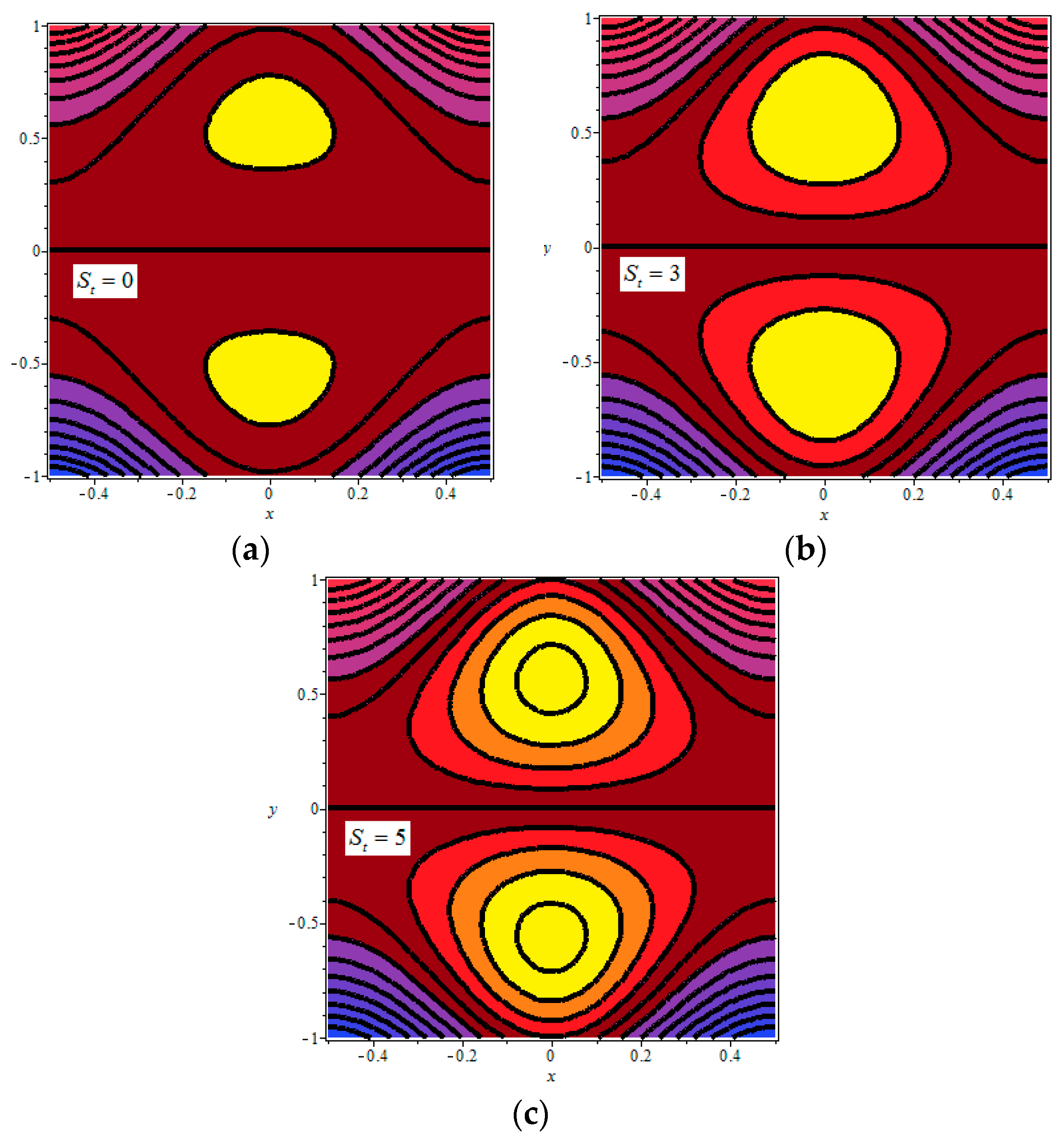
In ciliary-induced flows, trapping will exist due to metachronal waves of cilia and is recognized as a natural mechanism of physiological flows in the human body. It arises due to the circulation of streamlines at larger amount of volume flow rate. The streamlines are split to trap a bolus of the flowing material that will move as a whole with the wave speed along its direction. Figure 7, Figure 8, Figure 9 and Figure 10 explain the effects of key parameters , , , and on the 2D stream function . These graphs will explain the trapping behavior and circulation of the flow characteristics. The impacts of the magnetic field on the streamlines are displayed in Figure 7, which shows that the circulation as well as the size of trapped boluses gradually decrease due to increasing values of (the Hartmann number). From Figure 8, one can observe that the rise in the viscosity variation parameter markedly boosts the bolus growth and circulations in the streamlines. Figure 9 explains that the trapped boluses increase in size as well as in numbers with the increasing magnitude of , which indicates that the buoyancy force parameter promotes the formation of boluses in the cilia-driven flows. The streamlines in Figure 10 explain that the size as well as the numbers of the trapped boluses increase with the increasing magnitude of (heat source parameter). This confirms the previous observations that the occurrence of trapping will be enhanced when we increase the effects of heat transfer [24,25,26,27,28,29].
5. Application: Physiological Transport of Semen
The present study has a close relevance to the physiological flow of human semen through the efferent ducts of the male reproductive tract. It is now widely accepted that ciliary movements generating the metachronal waves have a significant role in the propulsion of semen through the ductile efferentes. Lardner and Shack [9] conducted experimental studies for various animals and found that the volume flow rate of human semen in the ductile efferent is approximately equal to 0.006 mL/h. In 1972, Lardner and Shack also developed a mathematical model describing the flow of a Newtonian viscous fluid through a 2D symmetric channel whose inner walls are ciliated. They calculated the values of non-dimensional volume flow rate and dimensional volume flow rate of the human semen by considering it to behave as a Newtonian viscous fluid to be 0.022 and 0.00012 mL/h, respectively. While calculating these values, the following data were used:
In this study, we aim to investigate the impacts of heat transfer and applied magnetic field on the volume flow rate of human semen through a 2D channel. Table 1 describes the numerical values of and its dimensional counterpart for various values of the Hartmann number , the viscosity variation parameter , the Grashof number (the buoyancy force parameter) and the heat source (sink) parameter . From Table 1, we note that the flow rate increases with the increasing values of , and , whereas it decreases with the increasing values of the Hartmann number. We also observed that the volume flow rate for the conducting fluid is lower in magnitude as compared to the non-conducting fluid and this trend has been noticed in many studies [24,25,26,27,28,29]. Moreover, it is interesting to mention that the results of the present model are similar to those obtained in [9] for , , and .
These values do not agree with the estimated values of the volume flow rate of human semen (i.e., 0.006 mL/h). This suggests that a considerable improvement is needed in the model of Lardner and Shack [9]. However, when we choose , , , , we obtain , and . These values are comparatively closer to the experimentally estimated values. We hope that the present results are reasonably utilized in investigating the physiological flows inside the human vessels and as well in contriving the magnetically actuated artificial cilia in lab-on-chip devices.
6. Conclusions
An analysis of heat transfer effects on the ciliary pumping system in propelling biological fluids like blood, semantic is carried out under the influence of magnetic body force. The heat transfer features are characterized by the adding external heat source (sink) elements. The fluid viscosity depends upon the temperature according to the Reynolds law. In order to provide the generality and correctness of the present model, we would like to say that our model contains the results of Lardner and Shack [9] for , , , and ; and the results of Siddiqui et al. [12] for , , and . The numerical results of the volume flow rate obtained in this study are in GOOD agreement with the experimental values of the flow rate of the human semen estimated by Lardner and Shack [9]. This study reveals that the applied magnetic field exhibits strong decelerating consequences on the volume flow rate. Thus, the magnetic field can be used to achieve a better control on the flow rate. This phenomenon has useful applications in medical sciences and in the design of artificial cilia for the drug delivery system. Another important observation of this study is that the volume flow rate can be significantly accelerated due to increasing the heat transfer effects (Grashof number and heat source parameter), i.e., heat transfer assists the ciliary induced pumping. We also note that the magnetic field can control the development of trapping.
Author Contributions
Conceptualization, A.A.F. and Z.S.; methodology, E.O.A.; software, A.A.F.; validation, E.O.A. and Z.S.; formal analysis, A.A.F.; investigation, Z.S.; resources, E.O.A.; data curation, Z.S.; writing–original draft preparation, A.A.F. and Z.S.; writing–review and editing, E.O.A.; visualization, Z.S.; supervision, Z.S.
Funding
The authors received no financial support for the research, authorship, and/or publication of this article.
Conflicts of Interest
The authors declare no conflict of interest.
Appendix A
References
- Blake, J.R.; Sleigh, M.A. Mechanics of Ciliary Locomotion. Biol. Rev. 1974, 49, 85–125. [Google Scholar] [CrossRef] [PubMed]
- Liron, N.; Mochon, S. Stokes flow for a stokeslet between two parallel flat plates. J. Eng. Math. 1976, 10, 287. [Google Scholar] [CrossRef]
- Sleigh, M.A. The Biology of Cilia and Flagella; MacMillian: New York, NY, USA, 1962. [Google Scholar]
- Ibanez-Tallon, I.; Heintz, N.; Omran, H. To beat or not to beat: Role of cilia in development and disease. Hum. Mol. Genet. 2003, 12, 27–35. [Google Scholar] [CrossRef] [PubMed]
- Dauptain, A.; Favier, J.; Battaro, A. Hydrodynamics of ciliary propulsion. J. Fluids Struct. 2008, 24, 1156–1165. [Google Scholar] [CrossRef] [Green Version]
- Velez-Cordero, J.R.; Lauga, E. Waving transport and propulsion in a generalized Newtonian fluid. J. Non-Newton. Fluid Mech. 2013, 199, 37–50. [Google Scholar] [CrossRef] [Green Version]
- Brown, J.M.; Witman, G.B. Cilia and Diseases. Biosciences 2014, 64, 1126–1137. [Google Scholar] [CrossRef]
- Hanasoge, S.; Hesketh, P.J.; Alexeev, A. Metachronal motion of artificial cilia. Soft Matter. 2018, 14, 3689–3693. [Google Scholar] [CrossRef]
- Lardner, T.J.; Shack, W.J. Cilia Transport. Bull. Math. Biophys. 1972, 34, 25–35. [Google Scholar] [CrossRef]
- Agrawal, L.; Anawaruddin. Cilia transport of bio-fluid with variable viscosity. Indian J. Pure Appl. Math. 1984, 15, 1128–1139. [Google Scholar]
- Mills, Z.G.; Aziz, A.; Alexeev, A. Beating synthetic cilia enhance heat transport in micro fluidic channels. Soft Matter. 2012, 8, 11508–11513. [Google Scholar] [CrossRef]
- Siddiqui, A.M.; Farooq, A.A.; Rana, M.A. Hydromagnetic flow of Newtonian fluid due to ciliary motion in a channel. Magnetohydrodynamics 2014, 50, 109–122. [Google Scholar]
- Nadeem, S.; Sadaf, H. Trapping study of nanofluids in an annulus with cilia. AIP Adv. 2015, 5, 127204. [Google Scholar] [CrossRef] [Green Version]
- Sadaf, H.; Nadeem, S. Influences of slip and Cu-blood nanofluid in a physiological study of cilia. Comput. Methods Programs Biomed. 2016, 131, 169–180. [Google Scholar] [CrossRef] [PubMed]
- Farooq, A.A.; Siddiqui, A.M. Mathematical model for the ciliary induced transport of seminal liquids through the ductuli efferentes. Int. J. Biomath. 2017, 10, 1750031. [Google Scholar] [CrossRef]
- Farooq, A.A. On the transport of epididymal fluid induced by metachronal wave of cilia. J. Eng. Math. 2018, 110, 167–180. [Google Scholar] [CrossRef]
- Ponalagusamy, R. Mathematical analysis of flow of non-Newtonian fluid due to metachronal beating of cilia in a tube and its physiological applications. Appl. Math. Comput. 2018, 337, 545–561. [Google Scholar] [CrossRef]
- Nadeem, S.; Sadaf, S. Metachronal wave of cilia transport in a curved channel. Z. Naturforsch. 2015, 70, 33–38. [Google Scholar] [CrossRef]
- Farooq, A.A.; Tripathi, D.; Elnaqeeb, T. On the propulsion of micropolar fluid inside a channel due to ciliary induced metachronal wave. Appl. Math. Comput. 2019, 347, 225–235. [Google Scholar] [CrossRef]
- Akbar, N.S.; Tripathi, D.; Beg, O.A.; Khan, Z.H. MHD dissipative flow and heat transfer of Casson fluid due to metachronal wave propulsion of beating cilia with thermal and velocity slip effects under oblique magnetic field. Acta Astronaut. 2016, 128, 1–12. [Google Scholar] [CrossRef]
- Shaheen, A.; Nadeem, S. Metachronal wave analysis for non-Newtonian fluid under Thermophoresis and Brownian motion effects. Results Phys. 2017, 7, 2950–2957. [Google Scholar] [CrossRef]
- Akbar, N.S.; Khan, Z.H. Influence of magnetic field for metachoronical beating of cilia for nanofluid with Newtonian heating. J. Magn. Magn. Mater. 2015, 381, 235–242. [Google Scholar] [CrossRef]
- Akbar, N.S.; Khan, Z.H.; Nadeem, S. Metachronal beating of cilia under influence of Hartmann layer and heat transfer. Eur. Phys. J. Plus 2014, 129, 176. [Google Scholar] [CrossRef]
- Tripathi, D.; Bég, O.A. A study of unsteady physiological magneto-fluid flow and heat transfer through a finite length channel by peristaltic pumping. Proc. Inst. Mech. Eng. Part H J. Eng. Med. 2012, 226, 631–644. [Google Scholar] [CrossRef]
- Nadeem, S.; Hayat, T.; Akbar, N.S.; Malik, M.Y. On the influence of heat transfer in peristalsis with variable viscosity. Int. J. Heat Mass Transf. 2009, 52, 4722–4730. [Google Scholar] [CrossRef]
- Nadeem, S.; Akbar, N.S. Influence of temperature dependent viscosity on peristaltic transport of a Newtonian fluid: Application of an endoscope. Appl. Math. Comput. 2010, 216, 3606–3619. [Google Scholar] [CrossRef]
- Nadeem, S.; Akbar, N.S. Effects of heat transfer on the peristaltic transport of MHD Newtonian fluid with variable viscosity: Application of Adomian decomposition method. Commun. Nonlinear Sci. Numer. Simul. 2009, 14, 3844–3855. [Google Scholar] [CrossRef]
- Shit, G.C.; Ranjit, N.K.; Shina, A. Adomian Decomposition Method for Magnetohydrodynamic flow of blood induced by peristaltic waves. J. Mech. Med. Biol. 2017, 17, 1750007. [Google Scholar] [CrossRef]
- Rathod, V.P.; Laxni, D. Effects of heat transfer on the peristaltic MHD flow of a Binghamfluid through a porous medium in a channel. Int. J. Biomath. 2014, 7, 1450060. [Google Scholar] [CrossRef]
- Manzoor, N.; Maqbool, K.; Beg, O.A.; Shaheen, S. Adomian decomposition solution for propulsion of dissipative magnetic Jeffrey biofluid in a ciliated channel containing a porous medium with forced convection. Heat Transf. Asian Res 2018, 48, 556–581. [Google Scholar] [CrossRef]
- Kefayati, G. Lattice Boltzmann simulation of double-diffusive natural convection of viscoplastic fluids in a porous cavity. Phys. Fluids 2019, 31, 1. [Google Scholar] [CrossRef]
- Kefayati, G.H.R.; Tang, H. Three-dimensional Lattice Boltzmann simulation on thermosolutal convection and entropy generation of Carreau-Yasuda fluids. Int. J. Heat Mass Transf. 2019, 131, 346–364. [Google Scholar] [CrossRef]
- Kefayati, G.H.; Hosseinizadeh, S.F.; Gorji, M.; Sajjadi, H. Lattice Boltzmann simulation of natural convection in tall enclosures using water/SiO2 nanofluid. Int. Commun. Heat Mass Transf. 2011, 38, 798–805. [Google Scholar] [CrossRef]
- Ellahi, R.; Sait, S.M.; Shehzad, N.; Mobin, N. Numerical Simulation and Mathematical Modeling of Electro-Osmotic Couette–Poiseuille Flow of MHD Power-Law Nanofluid with Entropy Generation. Symmetry 2019, 11, 1038. [Google Scholar] [CrossRef]
- Ellahi, R.; Zeeshan, A.; Hussain, F.; Abbas, T. Two-Phase Couette Flow of Couple Stress Fluid with Temperature Dependent Viscosity Thermally Affected by Magnetized Moving Surface. Symmetry 2019, 11, 647. [Google Scholar] [CrossRef]
- Jawad, M.; Shah, Z.; Islam, S.; Majdoubi, J.; Tlili, I.; Khan, W.; Khan, I. Impact of Nonlinear Thermal Radiation and the Viscous Dissipation Effect on the Unsteady Three-Dimensional Rotating Flow of Single-Wall Carbon Nanotubes with Aqueous Suspensions. Symmetry 2019, 11, 207. [Google Scholar] [CrossRef]
- Saeed, A.; Islam, S.; Dawar, A.; Shah, Z.; Kumam, P.; Khan, W. Influence of Cattaneo–Christov Heat Flux on MHD Jeffrey, Maxwell, and Oldroyd-B Nanofluids with Homogeneous-Heterogeneous Reaction. Symmetry 2019, 11, 439. [Google Scholar] [CrossRef]
- Alzahrani, E.; Shah, Z.; Alghamdi, W.; Zaka Ullah, M. Darcy–Forchheimer Radiative Flow of Micropoler CNT Nanofluid in Rotating Frame with Convective Heat Generation/Consumption. Processes 2019, 7, 666. [Google Scholar] [CrossRef]
- Shah, Z.; Bonyah, E.; Islam, S.; Khan, W.; Ishaq, M. Radiative MHD thin film flow of Williamson fluid over an unsteady permeable stretching sheet. Heliyon 2018, 4, e00825. [Google Scholar] [CrossRef] [Green Version]
- Ullah, A.; Shah, Z.; Kumam, P.; Ayaz, M.; Islam, S.; Jameel, M. Viscoelastic MHD Nanofluid Thin Film Flow over an Unsteady Vertical Stretching Sheet with Entropy Generation. Processes 2019, 7, 262. [Google Scholar] [CrossRef]
- Sheikholeslami, M.; Shah, Z.; Shafee, A.; Khan, I.; Tlili, I. Uniform magnetic force impact on water based nanofluid thermal behavior in a porous enclosure with ellipse shaped obstacle. Sci. Rep. 2019, 9, 1196. [Google Scholar] [CrossRef]
- Marin, M.; Vlase, S.; Ellahi, R.; Bhatti, M. On the Partition of Energies for the Backward in Time Problem of Thermoelastic Materials with a Dipolar Structure. Symmetry 2019, 11, 863. [Google Scholar] [CrossRef]
- Ullah, A.; Alzahrani, E.; Shah, Z.; Ayaz, M.; Islam, S. Nanofluids thin film flow of Reiner-Philippoff fluid over an unstable stretching surface with Brownian motion and thermophoresis effects. Coatings 2019, 9, 21. [Google Scholar] [CrossRef]
- Shah, Z.; Islam, S.; Ayaz, H.; Khan, S. Radiative heat and mass transfer analysis of micropolar nanofluid flow of Casson fluid between two rotating parallel plates with effects of Hall current. J. Heat Transf. 2019, 141, 022401. [Google Scholar] [CrossRef]
- Ameen, I.; Shah, Z.; Islam, S.; Nasir, S.; Khan, W.; Kumam, P.; Thounthong, P. Hall and Ion-Slip Effect on CNTS Nanofluid over a Porous Extending Surface through Heat Generation and Absorption. Entropy 2019, 21, 801. [Google Scholar] [CrossRef]
- Mebarek-Oudina, F. Convective heat transfer of Titania nanofluids of di_erent base fluids in cylindrical annulus with discrete heat source. Heat Tran. Asian Res. 2019, 48, 135–147. [Google Scholar] [CrossRef]
- Mebarek-Oudina, F.; Bessaih, R. Oscillatory Magnetohydrodynamic Natural Convection of Liquid Metal between Vertical Coaxial Cylinders. J. Appl. Fluid Mech. 2016, 9, 1655–1665. [Google Scholar] [CrossRef]
- Saeed, A.; Shah, Z.; Islam, S.; Jawad, M.; Ullah, A.; Gul, T.; Kumam, P. Three-Dimensional Casson Nanofluid Thin Film Flow over an Inclined Rotating Disk with the Impact of Heat Generation/Consumption and Thermal Radiation. Coatings 2019, 9, 248. [Google Scholar] [CrossRef]
- Ahmad, M.W.; Kumam, P.; Shah, Z.; Farooq, A.A.; Nawaz, R.; Dawar, A.; Islam, S.; Thounthong, P. Darcy–Forchheimer MHD Couple Stress 3D Nanofluid over an Exponentially Stretching Sheet through Cattaneo–Christov Convective Heat Flux with Zero Nanoparticles Mass Flux Conditions. Entropy 2019, 21, 867. [Google Scholar] [CrossRef]
- Shah, Z.; Ullah, A.; Bonyah, E.; Ayaz, M.; Islam, S.; Khan, I. Hall effect on Titania nanofluids thin film flow and radiative thermal behavior with different base fluids on an inclined rotating surface. AIP Adv. 2019, 9, 055113. [Google Scholar] [CrossRef] [Green Version]
Figure 1.
Ciliated channel with metachronal waves.

Figure 2.
for (a) (b) (c) (d) . The other parameters are fixed as , , , , , , , .


Figure 3.
for (a) (b) (c) (d) . The other parameters are fixed as , , , , , , , .

Figure 4.
Pressure difference () versus the flow rate () for (a) (b) (c) (d) . The other parameters are fixed as , , , , , , .
Figure 4.
Pressure difference () versus the flow rate () for (a) (b) (c) (d) . The other parameters are fixed as , , , , , , .

Figure 5.
Volume flow rate () versus for (a) , (b) , (c) , (d) . The other parameters are fixed as , , , , , , .
Figure 5.
Volume flow rate () versus for (a) , (b) , (c) , (d) . The other parameters are fixed as , , , , , , .

Figure 6.
Volume flow rate () versus for (a) (b) . The other parameters are fixed as , , , , , , .

Figure 7.
Streamlines for (a) , (b) , (c) . The other parameters are fixed as , , , , , , , .

Figure 8.
Streamlines for (a) , (b) , (c) . The other parameters are fixed as , , , , , , .

Figure 9.
Streamlines for (a) , (b) , (c) . The other parameters are fixed as , , , , , , , .

Figure 10.
Streamlines for (a) , (b) , (c) . The other parameters are fixed as , , , , , , , .


Table 1.
Numerical results of and , when , , , and .
| 0 | 0 | 0 | 0 | 0.02204 | 0.00012 |
| 0.01 | 0.1 | 0.1 | 0.05957 | 0.00032 | |
| 0.02 | 0.1 | 0.1 | 0.06443 | 0.00035 | |
| 0.03 | 0.1 | 0.1 | 0.07071 | 0.00038 | |
| 0.1 | 0.01 | 0.1 | 0.1 | 0.05932 | 0.00032 |
| 0.02 | 0.1 | 0.1 | 0.06411 | 0.00034 | |
| 0.03 | 0.1 | 0.1 | 0.07029 | 0.00031 | |
| 0.01 | 0.3 | 0.1 | 0.13398 | 0.00073 | |
| 0.01 | 0.5 | 0.1 | 0.20864 | 0.00113 | |
| 0.01 | 0.1 | 0.3 | 0.06249 | 0.00034 | |
| 0.01 | 0.1 | 0.5 | 0.06569 | 0.00035 | |
| 0.3 | 0.01 | 0.1 | 0.1 | 0.05716 | 0.00031 |
| 0.5 | 0.01 | 0.1 | 0.1 | 0.05208 | 0.00028 |
© 2019 by the authors. Licensee MDPI, Basel, Switzerland. This article is an open access article distributed under the terms and conditions of the Creative Commons Attribution (CC BY) license (http://creativecommons.org/licenses/by/4.0/).
Share and Cite
MDPI and ACS Style
Ahmad Farooq, A.; Shah, Z.; Alzahrani, E.O. Heat Transfer Analysis of a Magneto-Bio-Fluid Transport with Variable Thermal Viscosity Through a Vertical Ciliated Channel. Symmetry 2019, 11, 1240. https://doi.org/10.3390/sym11101240
AMA Style
Ahmad Farooq A, Shah Z, Alzahrani EO. Heat Transfer Analysis of a Magneto-Bio-Fluid Transport with Variable Thermal Viscosity Through a Vertical Ciliated Channel. Symmetry. 2019; 11(10):1240. https://doi.org/10.3390/sym11101240
Chicago/Turabian StyleAhmad Farooq, Ali, Zahir Shah, and Ebraheem O. Alzahrani. 2019. "Heat Transfer Analysis of a Magneto-Bio-Fluid Transport with Variable Thermal Viscosity Through a Vertical Ciliated Channel" Symmetry 11, no. 10: 1240. https://doi.org/10.3390/sym11101240
Note that from the first issue of 2016, this journal uses article numbers instead of page numbers. See further details here.