
A Unified Solution for Surrounding Rock of Roadway Considering Seepage, Dilatancy, Strain-Softening and Intermediate Principal Stress


Abstract
:1. Introduction
2. Unified Strength Theory
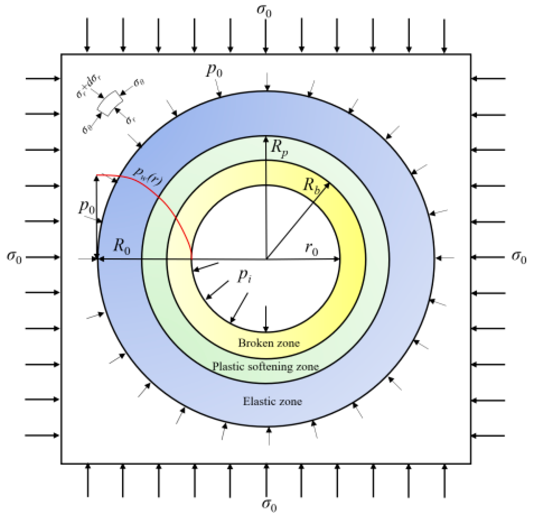
3. Mechanical Model for Surrounding Rock of Roadway
3.1. Distribution of Pore Water Pressure
3.2. Elastoplastic Solution of Mechanical Model
3.2.1. Basic Equations under Polar Coordinate System
3.2.2. Analytical Solutions of Displacement and Stress in Elastic Zone
3.2.3. Analytical Solutions of Displacement and Stress in Plastic Softening Zone
3.2.4. Analytical Solutions for Displacement and Stress in Broken Zone
3.2.5. Radii of Plastic Zones
3.3. Validation of Unified Analytical Solution
4. Example Analysis
4.1. Influence of Water Seepage
4.2. Influence of Strain Softening
4.3. Influence of Dilatancy
4.4. Influence of Intermediate Principal Stress
4.5. Influence of Residual Cohesion
5. Conclusions
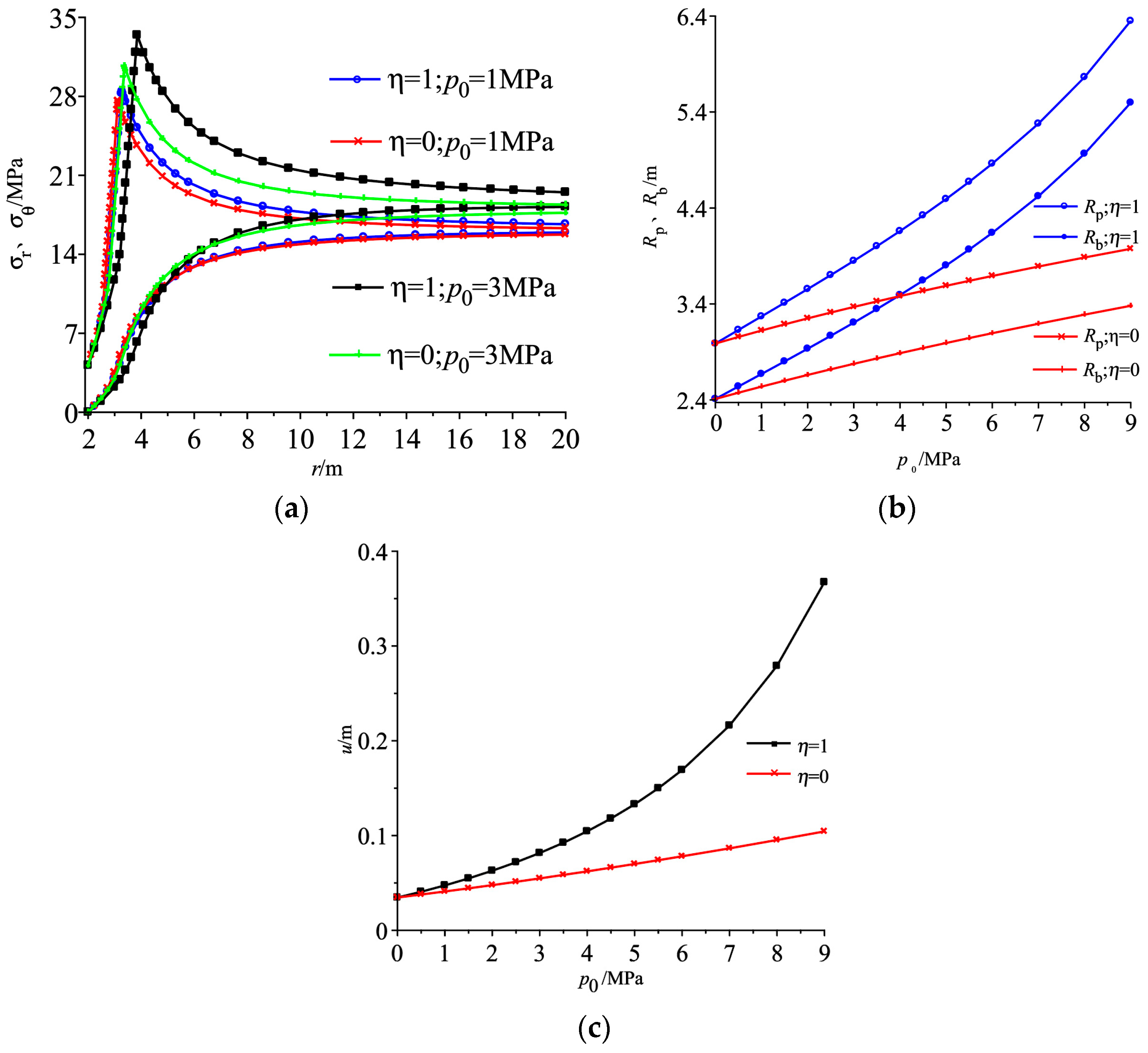
- (1)
- With water pressure increasing, peak circumferential stress, radii of two plastic zones and surface displacement of roadway with water seepage considered would increase, and their magnitudes are all greater than their corresponding conditions with water seepage not considered. Particularly, radii of plastic zones and surface displacement of roadway increases exponentially with water pressure increasing, water seepage influence should be carefully considered to ensure roadway stability under groundwater environment.
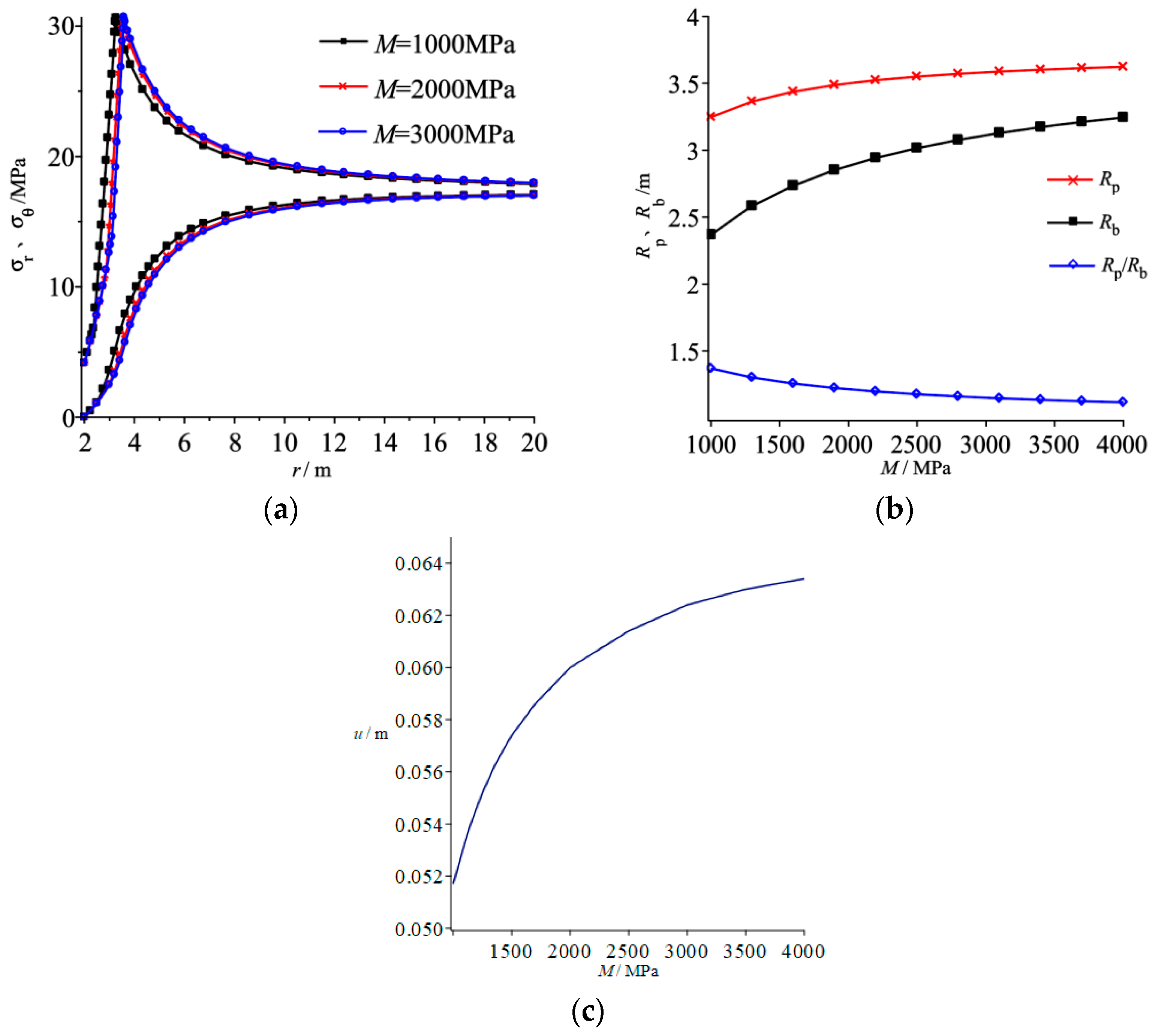
- (2)
- With softening modulus increasing, the magnitude of peak circumferential stress is kept unchanged, and location of peak circumferential stress would slightly shift to the deeper surrounding rock. Softening modulus has a greater influence on broken zone radius than that of strain-softening zone radius, and it also affects surface displacement of roadway to an extent. To accurately predict broken zone radius and surface displacement of roadway, strain-softening characteristics of surrounding rock should be analyzed; and length of rock bolt should be increased with softening modulus increasing for bolting support roadway.
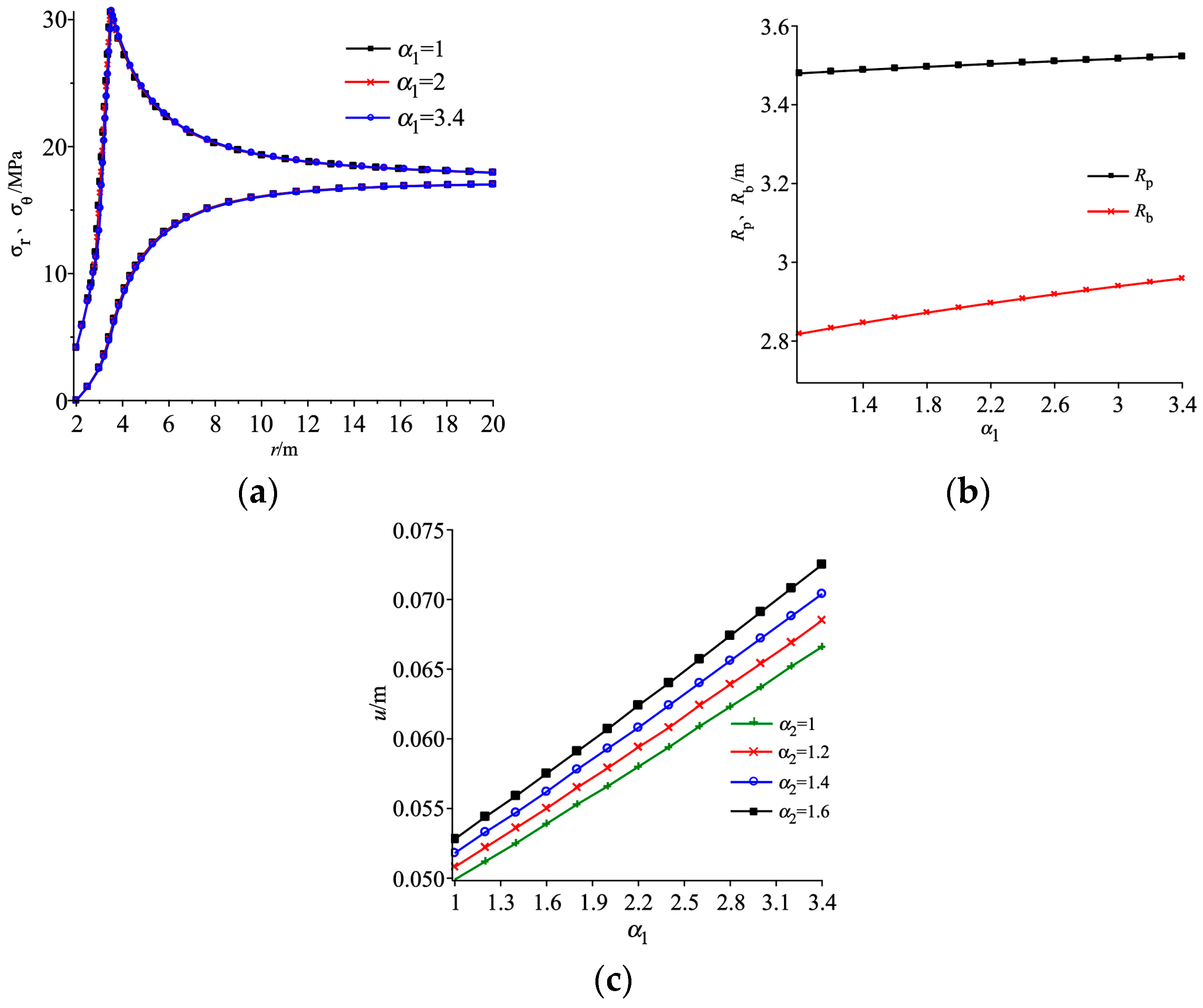
- (3)
- Rock dilatancy coefficient has little effect on magnitude of peak circumferential stress and plastic softening zone radius, while radius of broken zone and surface displacement of roadway increase linearly with dilatancy coefficient α1 increasing. For actual engineering, surface displacement of roadway would be underestimated with rock dilatancy not considered, while they are overestimated if associated flow rule is adopted, indicating that flow rule of rock should be reasonably chosen for calculating roadway surface displacement and broken zone radius of roadway.
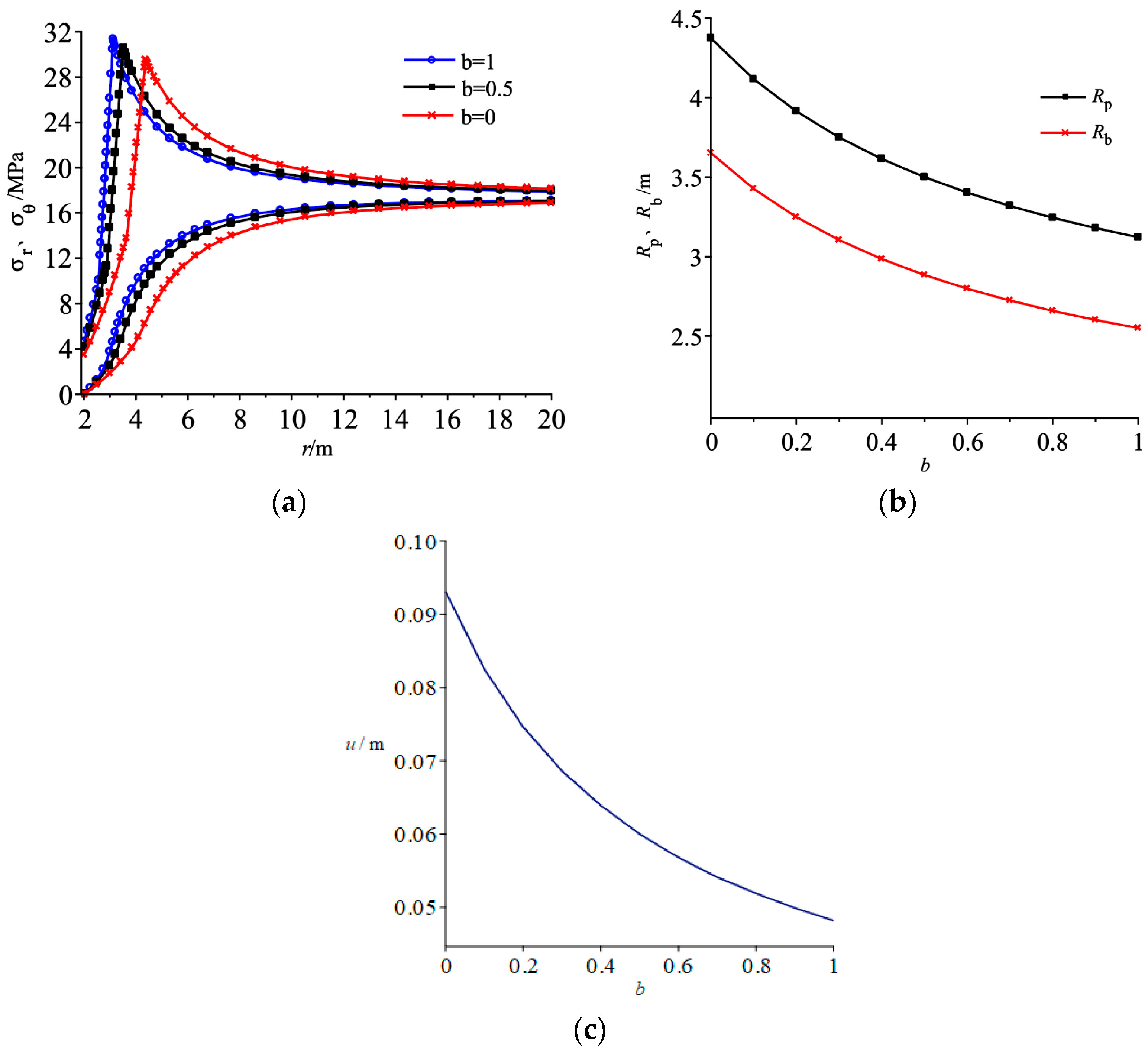
- (4)
- With weighted coefficient increasing, stress components in plastic zones at the same distance from roadway center would increase; while the distance of peak circumferential stress location from roadway center, radii of broken and plastic softening zones, and surface displacement of roadway are reduced. Self-bearing capacity enhancement of surrounding rock resulting from effect of intermediate principal stress should be considered. The traditional Mohr–Coulomb criterion is more conservative. Rock bolt length and grouting range can be decreased after considering effect of inter-mediate principal stress, which is helpful for reasonable measure selection of surrounding rock.
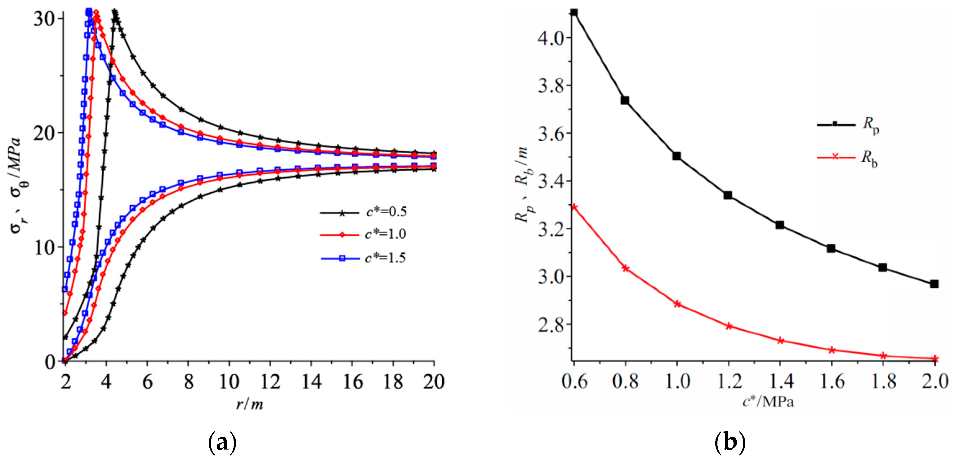
- (5)
- With residual cohesion increasing, peak circumferential stress remains unchanged, stress components in plastic zones at the same distance from roadway center would increase, and the distance of plastic–elastic interface from roadway center decreases, which implicates that grouting measure can be adopted to improve roadway stability effectively.
Author Contributions
Funding
Informed Consent Statement
Data Availability Statement
Conflicts of Interest
References
- Kang, H.P. Seventy years development and prospects of strata control technologies for coal mine roadways in China. Chinese J. Rock Mech. Eng. 2021, 40, 1–30. [Google Scholar]
- Li, Z.L.; Ren, Q.W.; Wang, Y.H. Elasto -plastic analytical solution of deep-buried circle tunnel considering fluid flow field. Chin. J. Rock Mech. Eng. 2004, 23, 1291–1295. [Google Scholar]
- Yao, G.S.; Li, J.P.; Gu, S.C. Analytic solution to deformation of soft rock tunnel considering dilatancy and plastic softening of rock Mass. Rock Soil Mech. 2009, 30, 463–467. [Google Scholar]
- Zhang, Q.; Wang, S.L.; Ge, X. Elastoplastic analysis of circular openings in strain-softening rock masses. Chin. J. Rock Mech. Eng. 2010, 29, 1031–1035. [Google Scholar]
- Zhang, X.B.; Zhao, G.M.; Meng, X.R. Elastoplastic solution for surrounding rock of circular roadway based on D-P criterion by considering post-peak strain softening and dilatancy. J. Min. Saf. Eng. 2013, 30, 903–910. [Google Scholar]
- Lv, A.; Ramandi, H.L.; Masoumi, H.; Saadatfar, M.; Regenauer-Lieb, K.; Roshan, H. Analytical and experimental investigation of pore pressure induced strain softening around boreholes. Int. J. Rock Mech. Min. Sci. 2019, 113, 1–10. [Google Scholar] [CrossRef]
- Xie, S.Y.; Shao, J.F. Elastoplastic deformation of a porous rock and water interaction. Int. J. Plast. 2006, 22, 2195–2225. [Google Scholar] [CrossRef]
- Zhang, K.X.; Huang, Z.H.; Zhang, J.H.; Wang, X.; Ma, Z.; Yang, Y. Failure features and instability mechanism of mine mudstone roadway under role of high-pressure seepage water. Coal Sci. Technol. 2015, 43, 1–5. [Google Scholar]
- Zhang, B.Q.; Chen, F.Q.; Wang, Q.Y. Elastoplastic solutions for surrounding rock masses of deep-buried circular tunnels with non-darcian flow. Int. J. Geomech. 2019, 19, 301–317. [Google Scholar] [CrossRef]
- Gu, S.C.; Zhou, P.; Sun, W.; Hu, C.; Li, Z.; Wang, C. Analysis of surrounding rock stability of bolted roadway considering dilatancy and intermediate principal stress. J. Min. Saf. Eng. 2019, 36, 429–436. [Google Scholar]
- Pan, J.L.; Ren, F.H. Analytical solution for surrounding rock of circular roadway based on generalized SMP criterion considering seepage and dilatancy. Coal Geol. Explor. 2019, 47, 32–39. [Google Scholar]
- Pan, J.L.; Guo, Q.F.; Ren, F.H.; Cai, M. Comparative analysis of different strength criteria for deep-buried rock roadway under seepage. J. China Coal Soc. 2019, 44, 3369–3378. [Google Scholar]
- Liu, Z.Q.; Yu, D.M. Elastoplastic stress and displacement analytical solutions to deep-buried circular tunnels considering intermediate principal stress and dilatancy. Eng. Mech. 2012, 29, 289–296. [Google Scholar]
- Zhang, Q.; Jiang, B.S.; Wang, S.L.; Ge, X.R.; Zhang, H.Q. Elasto-plastic analysis of a circular opening in strain-softening rock mass. Int. J. Rock Mech. Min. Sci. 2012, 50, 38–46. [Google Scholar] [CrossRef]
- Gao, Z.N.; Meng, X.R.; Fu, Z.L. Elasto-plastic analysis on surrounding rock of roadways based on seepage, strain softening and dilatancy. J. Chongqing Univ. 2014, 37, 96–101. [Google Scholar]
- Fan, H.; Liu, W.R.; Fu, T.F.; Li, S. Stability analysis of surrounding rock of tunnel considering seepage, shear dilation and intermediate principal stress. China Saf. Sci. J. 2016, 26, 139–145. [Google Scholar]
- Liu, W.R. Analysis of deformation of circular roadway considering effects of intermediate principal stress and dilatancy. Geotech. Geol. Eng. 2019, 2020, 529–536. [Google Scholar] [CrossRef]
- Guo, Q.F.; Pan, J.L.; Wu, X.H.; Xi, X.; Cai, M. A new unified solution for circular tunnels based on generalized smp criterion considering the strain softening and dilatancy. Adv. Civ. Eng. 2019, 2019, 1684707. [Google Scholar] [CrossRef] [Green Version]
- Wang, R.; Bai, J.B.; Yan, S.; Chang, Z.G.; Song, Y.B.; Zhang, W.G.; Xu, J. The elastoplastic solutions of deep buried roadway based on the generalized 3D hoek-brown strength Criterion considering strain-softening properties. Geofluids 2021, 2021, 5575376. [Google Scholar] [CrossRef]
- Deng, Y.S.; Wang, J.X.; Zou, B.P. Elastoplastic analysis for circular tunnel based on modified lade criterion considering strain softening and dilatancy. Adv. Civ. Eng. 2021, 2021, 4872558. [Google Scholar] [CrossRef]
- Wang, R.; Liu, X.D.; Bai, J.B.; Yan, S.; Xu, J. An innovative elastoplastic analysis for soft surrounding rock considering supporting opportunity based on drucker-prager strength criterion. Adv. Civ. Eng. 2021, 2021, 5555839. [Google Scholar] [CrossRef]
- Zhou, P.; Li, J.P.; Gu, S.C. A new analytical solution for deep-buried circular cavern with anchor reinforcement under seepage field. Arab. J. Geosci. 2021, 2021, 968–985. [Google Scholar] [CrossRef]
- Zhang, Q.; Shao, C.; Wang, H.Y.; Jiang, B.S.; Liu, R.C. A fully coupled hydraulic-mechanical solution of a circular tunnel in strain-softening rock masses. Tunn. Undergr. Space Technol. 2020, 99, 103375. [Google Scholar] [CrossRef]
- Deng, Y.S.; Wang, J.X.; Jiang, M.J.; Zou, B. Elasto-plastic analysis of circular tunnel in rock mass with confining stress-dependent strain-softening behavior considering intermediate principal stress. Arab. J. Geosci. 2021, 14, 2191. [Google Scholar] [CrossRef]
- Fan, H.; Wang, L.G.; Wang, S.; Jiang, C. A New Unified Solution for Deep Tunnels in Water-Rich Areas considering Pore Water Pressure. Geofluids 2021, 2021, 6696757. [Google Scholar] [CrossRef]
- Wang, L.; Zou, J.F.; Sheng, Y.M. An improved stress and strain increment approaches for circular tunnel in strain-softening surrounding rock considering seepage force. Adv. Mater. Sci. Eng. 2019, 2019, 2075240. [Google Scholar] [CrossRef] [Green Version]
- Yu, M.H.; Zan, Y.W.; Zhao, J.; Yoshimine, M. A unified strength criterion for rock material. Int. J. Rock Mech. Min. Sci. 2002, 39, 975–989. [Google Scholar] [CrossRef]
- Yuan, Z.G.; Shao, Y.H. Numerical modeling on hydraulic fracturing in coal-rock mass for enhancing gas drainage. Adv. Civ. Eng. 2018, 2018, 1485672. [Google Scholar] [CrossRef]
- Fang, Z.; Harrison, J.P. A mechanical degradation index for rock. Int. J. Rock Mech. Min. Sci. 2001, 38, 1193–1199. [Google Scholar] [CrossRef]
- Wu, S.C. Rock Mechanics; Higher Education Press: Beijing, China, 2021. [Google Scholar]


| Parameters | Values | Parameters | Values |
|---|---|---|---|
| Poisson’s ratio v | 0.25 | Dilatancy coefficient in plastic softening zone α1 | 2 |
| Elastic modulus E/MPa | 2000 | Dilatancy coefficient in broken zone α2 | 1.5 |
| Residual Cohesion c*/MPa | 1.0 | Softening modulus M/MPa | 2000 |
| Original Cohesion c/MPa | 3.0 | Internal friction angle φ/° | 30 |
| Weighted coefficient b | 0.5 | Initial pore water pressure p0/MPa | 2 |
Publisher’s Note: MDPI stays neutral with regard to jurisdictional claims in published maps and institutional affiliations. |
© 2022 by the authors. Licensee MDPI, Basel, Switzerland. This article is an open access article distributed under the terms and conditions of the Creative Commons Attribution (CC BY) license (https://creativecommons.org/licenses/by/4.0/).
Share and Cite
Yuan, Z.; Zhao, J.; Li, S.; Jiang, Z.; Huang, F. A Unified Solution for Surrounding Rock of Roadway Considering Seepage, Dilatancy, Strain-Softening and Intermediate Principal Stress. Sustainability 2022, 14, 8099. https://doi.org/10.3390/su14138099
Yuan Z, Zhao J, Li S, Jiang Z, Huang F. A Unified Solution for Surrounding Rock of Roadway Considering Seepage, Dilatancy, Strain-Softening and Intermediate Principal Stress. Sustainability. 2022; 14(13):8099. https://doi.org/10.3390/su14138099
Chicago/Turabian StyleYuan, Zhigang, Jintao Zhao, Shuqing Li, Zehua Jiang, and Fei Huang. 2022. "A Unified Solution for Surrounding Rock of Roadway Considering Seepage, Dilatancy, Strain-Softening and Intermediate Principal Stress" Sustainability 14, no. 13: 8099. https://doi.org/10.3390/su14138099