
Temperature Distribution and Equipment Layout in a Deep Chamber: A Case Study of a Coal Mine Substation


1
School of Architecture, South China University of Technology, Guangzhou 510641, China
2
State Key Laboratory of Subtropical Building Science, South China University of Technology, Guangzhou 510641, China
3
Work Safety Key Lab on Prevention and Control of Gas and Roof Disasters for Southern Coal Mines, Hunan University of Science and Technology, Xiangtan 411201, China
4
School of Resources, Environment and Safety Engineering, Hunan University of Science and Technology, Xiangtan 411201, China
*
Authors to whom correspondence should be addressed.
Sustainability 2022, 14(7), 3852; https://doi.org/10.3390/su14073852
Submission received: 23 January 2022
/
Revised: 11 March 2022
/
Accepted: 15 March 2022
/
Published: 24 March 2022
(This article belongs to the Topic District Heating and Cooling Systems)
Abstract
:With the gradual depletion of shallow resources, the process of resource exploitation is being transferred to greater depths. The temperature of the surrounding rock increases gradually in the process of deep mining, and the temperature of the underground substation chambers often exceeds the normal working temperature in summer. In this paper, the equipment layout and ventilation conditions of the deep substation chamber of the Jiangxi Qujiang Mining Company were selected as the research subjects, and numerical simulation software was used to study the temperature distribution within the chamber under different conditions by changing the combinations of the wind velocity and air temperature of the inlet air of the chamber. The study showed that, under the conditions of the current equipment layout and air door size, the equipment temperature was prone to being too high in the summer. Therefore, the layout of the equipment was optimized based on the simulation results. The transformer equipment was changed from the original serial mode to the juxtaposed mode, and the size of the air door was increased, which effectively reduced the disturbance of the air flow and the length of the air flow path in the chamber. This meant that the high temperature area of the chamber was at the end of the chamber, which efficiently reduced the area of the high temperature zone and ensured that the equipment was in a lower temperature environment. This method can be used as a reference for temperature distribution, layout, and temperature control measures within buildings.
1. Research Status
With the increase in coal mining depth, the problem of high temperature is increasingly troubling for mining activities. Recently, some scholars have studied the temperature distribution of the heat-regulating circles of mines as well as the surrounding rock of the roadway. Numerical simulations and actual measurement analyses have been conducted on the radius of the heat regulating circle of the −965 m track roadway in a mine in Huainan and found that the radius of the heat regulating circle was about 33 m [1]. The distribution patterns of the temperature fields of the surrounding rock of the roadways with active thermal insulation in high-temperature mines have also been studied, and the distribution characteristics of the roadway heat regulating circles under the different thicknesses of thermal insulation layers have been analyzed [2]. The shape of the roadway section affects the heat dissipation pattern of the surrounding rock [3]. The high ground temperature of the roadway affects the temperature field of the surrounding rock and the distribution pattern of the air temperature inside the roadway [4]. Du et al. [5] proposed a calculation method for the radius and temperature of the heat regulating circle of a mine based on steady-state heat conduction. Han Fei et al. [6] conducted an experimental study on a similar simulation of the heat transfer of the surrounding rock of a mine. The cooling capacity of the underground chambers was calculated to reach the target temperature, and the researchers proposed a corresponding cooling scheme [7]. Wan et al. [8] conducted field measurements of the thermal environment in a specific high-temperature chamber (water pump room, winch room, and substation) that is located underground in Yongchuan Coal Mine. Shi et al. [9] conducted a simulation study on the ventilation scheme of substations in elevated subway stations and proposed layout design principles for those substations. Xu et al. [10] studied the cooling method and heat dissipation of a 500 kV transformer. Chen et al. [11] discussed the maintenance structure of a chamber and the absolute heat source of wind flow. Wang Hao [12] obtained a series of results that showed how setting an insulation layer could affect the distribution patterns of the temperature fields within and around roadways. A new arrangement of PCM packs was introduced that used 15 °C PCMs as the inner layer and 23 °C PCMs as the outer layer (15&23) [13]. Li et al. [14,15] studied the working principles of a vortex tube and performed a deep analysis of the heat damage in the south-central substation in the Zhaolou mine. Mutama et al. [16] employed a careful study of temperature conditions over time to determine that an evaporative cooling spray chamber would be sufficient to cool the airflow from the high dry bulb temperatures down to saturation at the wet bulb temperature. Thermal comfort model analysis and an optimization performance evaluation of a multifunctional ice storage air conditioning system have also been conducted in a confined mine refuge chamber [17]. Zhang et al. [18,19] conducted studies on the thermal performance of a mine refuge chamber with human body heat sources under ventilation. Xia et al. [20] conducted studies on the effects of cooling conditions on the surface properties of heated coal. Zhai et al. [21] conducted design and performance simulations of a novel liquid CO2 cycle refrigeration system for heat hazard control in coal mines. These studies have laid a solid foundation for the study of temperature distribution in deep substation chambers. This paper aimed to simulate and analyze the temperature distribution patterns and optimal layout of the deep substation chamber by building on these bases.
2. Analysis of the Heat Source and Its Environment in Deep Chambers
The temperature of the rock surrounding an underground chamber increases as the depth increases, with the temperature of the surrounding rock being the main heat source for deeper chambers. The internal temperature of some chambers is mainly affected by the temperature of the surrounding rock of the deeper chambers. When there is electromechanical equipment in the chambers, then the electromechanical equipment also generates a certain amount of heat according to its power.
2.1. Surrounding Rock of Deep Chambers: Principles of Heat Transfer through Air
Before the excavation of the underground chamber, the temperature within the rock mass around the chamber is the original rock temperature. The geothermal gradient of major underground spaces in China is divided into three regions: a region where the geothermal gradient is less than 2 °C/100 m; a region of 2–3 °C/100 m; and a region where the geothermal gradient is greater than 3 °C/100 m. For example, the temperature of the original rock of −1150 m in the Gucheng Coal Mine reached 32 °C and the temperature of the bottom rock of the −1250 working face of the Yaojiashan Coal Mine was over 40 °C.
After the excavation of the underground chamber, due to the temperature difference between the air in the chamber and the wall of the chamber, the temperature field of the surrounding rock of the underground chamber is redistributed by heat transfer. The process of convective heat transfer exists between the surrounding rock and the air inside the chamber, as well as between the air and the heat generating equipment in the chamber. According to Newton’s cooling formula, the heat flux of the convective heat transfer between the air and the wall (rock wall and equipment surface) is proportional to their temperature difference; that is:
where:
—Convective heat transfer ;
—Convective heat transfer coefficient ;
A—Surface area for convective heat transfer, m2;
—Temperature difference between air and surrounding rock wall .
For the circular roadway, under the premise that the surrounding rock of the roadway is homogeneous, the temperature distribution of the original rock within the surrounding rock of the roadway obeys the Fourier conduction differential equation to calculate the heat transfer process:
The initial conditions are:
The boundary conditions are:
where:
—Temperature at any point in the surrounding rock °C
—The thermal diffusivity of rock, m²/s;
—The distance between any point in the surrounding rock and the axis of the roadway, m2;
—The conductivity of rock W/(m°C).
From the calculation formula, it can be seen that the temperature field of the surrounding rock of the chamber is distributed around the center of the chamber after excavation. The temperature of the surrounding rock with the same radius from the center of the chamber is equal to the same value, while the temperature of the surrounding rock beyond a certain distance from the center of the chamber still maintains the original rock temperature, from which it can be inferred that there is an isotherm in the surrounding rock of the chamber, and the area surrounded by the temperature isotherm of the original rock is called the heat-regulating circle of the surrounding rock of the underground chamber [22].
2.2. Heat-Regulating Circle of Surrounding Rock in Deep Chamber
Theoretically, the relationship between the ventilation time of the roadway and the range of the heat-regulating circle can be calculated. The temperature distribution of the surrounding rock of the roadway varies depending on the ventilation time, and the radius of the heat-regulating circle changes with the ventilation time [23,24]; with the increase in ventilation time, the humidity inside the surrounding rock of the roadway gradually decreases, and the radius of the heat-regulating circle gradually expands to the deep part of the surrounding rock, but the expansion speed gradually decreases. According to the relevant data [25]: the radius of the heat-regulating circle is about 18 m for a roadway with one year of ventilation time, about 25 m for a roadway with two years of ventilation time, and about 40 m for a roadway with five years of ventilation time.
2.3. Characteristics of the Underground Air
Affected by the shaft, the characteristics of the underground air in deep coal mines are slightly different from surface air, mainly in terms of air temperature, humidity, and air pressure. Due to the influence of geothermal heat, the temperature of the underground is higher than that aboveground. Due to the influence of mine water in the shaft, the humidity of the underground air is higher than that aboveground. Because mines are mostly ventilated by negative pressure, the underground air pressure is lower than that at the same altitude [26], which is basically the same as the ground pressure at the entrance to the shaft.
For example, the ground temperature reaches 0 °C in winter, but the underground temperature can still be around 10 °C, and the surface temperature exceeds 30 °C in summer, but the underground temperature can still be around 26 °C.
3. Measurement Analysis of Cooling Demand in Deep Underground Chambers
3.1. Temperature Measurement of Surrounding Rock and Original Rock in Deep Buried Chambers
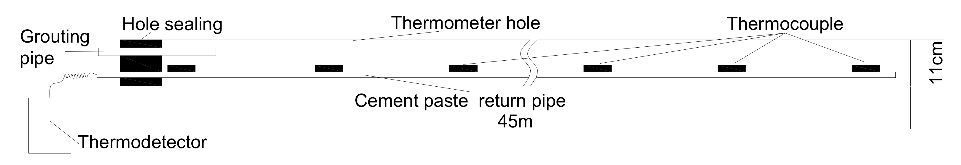
The measurement of the original rock temperature was performed in the Dongyi substation of Qujiang Mining Company. The drill hole diameter was 110 mm; the drilling hole was perpendicular to the surface of the chamber, the horizontal hole was designed with an elevation angle of 2 degrees, and the drilling depth was 45 m. After the hole was drilled and cleaned, the temperature sensors were installed in the hole. The temperature sensors were positioned 45 m, 40 m, 35 m, 30 m, 25 m, 20 m, 15 m, 10 m, 5 m, and 2 m from the orifice, as shown in Figure 1. Each temperature sensor was numbered at the outer end, and a PVC pipe with a diameter of 25 mm was used to transport and fix the temperature sensor in the temperature measurement hole. Each PVC pipe was 2 m long with quick connectors at both ends. After each temperature sensor was installed, we connected the thermometer in turn and checked whether the circuit was normal.
After the installation and debugging of the temperature sensor in the hole, the grouting pipe was inserted into the temperature measurement hole, and polyurethane was used to seal the hole for 1.5 m. After one day of polyurethane curing, the temperature measurement hole was filled by the grouting pipe with the grouting pressure of 2–3 MPa. The grouting material was cement slurry, and the water–cement ratio of the slurry was 1:1. We stopped grouting after the return of the grouting to the exit of the PVC pipe; then, we blocked the exit of the PVC pipe; then, we stopped grouting after 2 min of a steady pressure of grouting. Then, the temperature of each measuring point was measured to obtain the final temperature distribution in the surrounding rock of the substation chamber, as shown in Figure 2. The temperature measurement time was in summer, and the temperature at the entrance to the chamber was about 25 °C. As shown in Figure 2, it was determined that the control of Qujiang Coal Mine and the radius of the heat-regulating circle of the roadway was around 40 m.
3.2. Basic Parameters of the Deep Underground Chamber
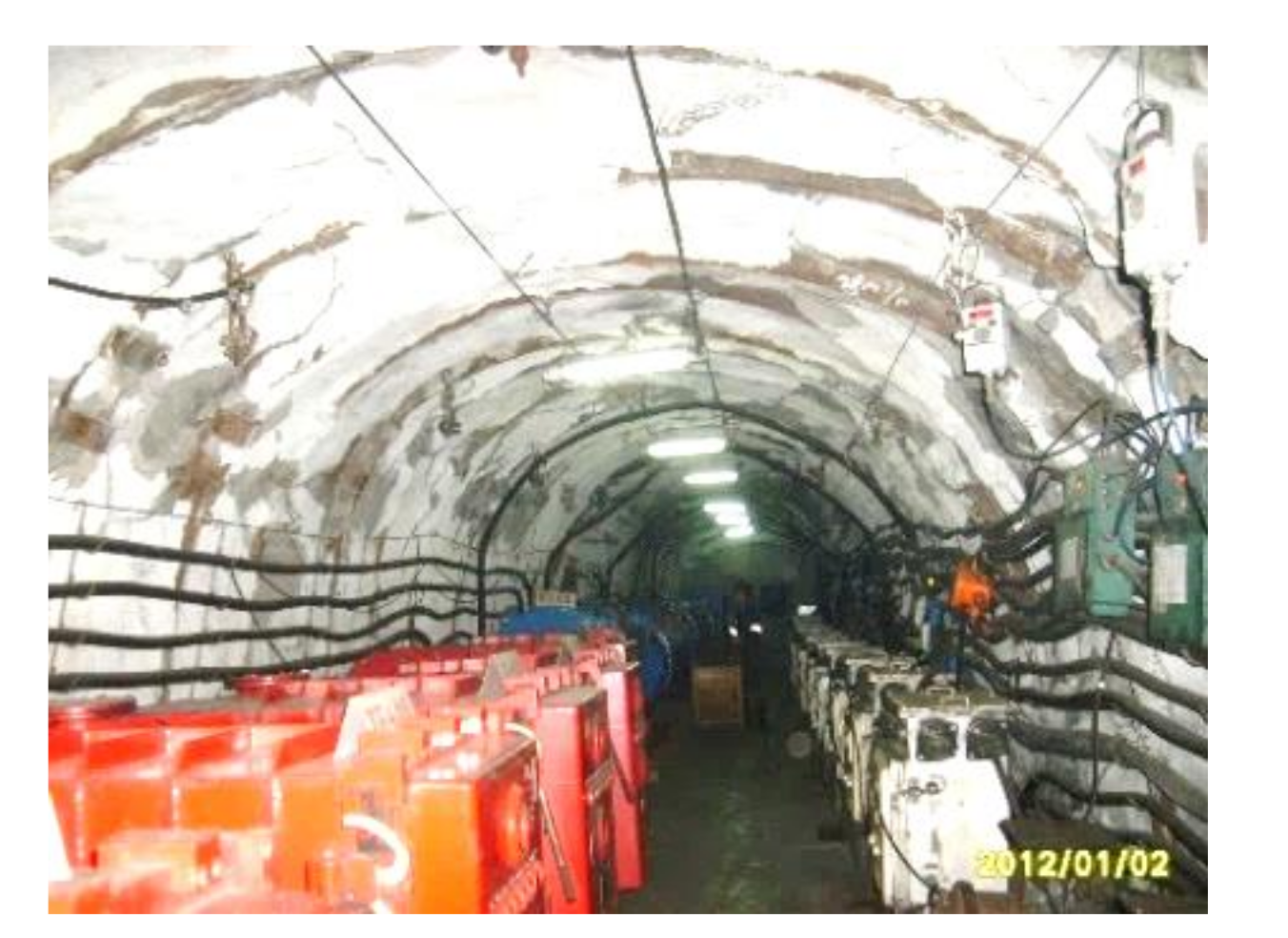
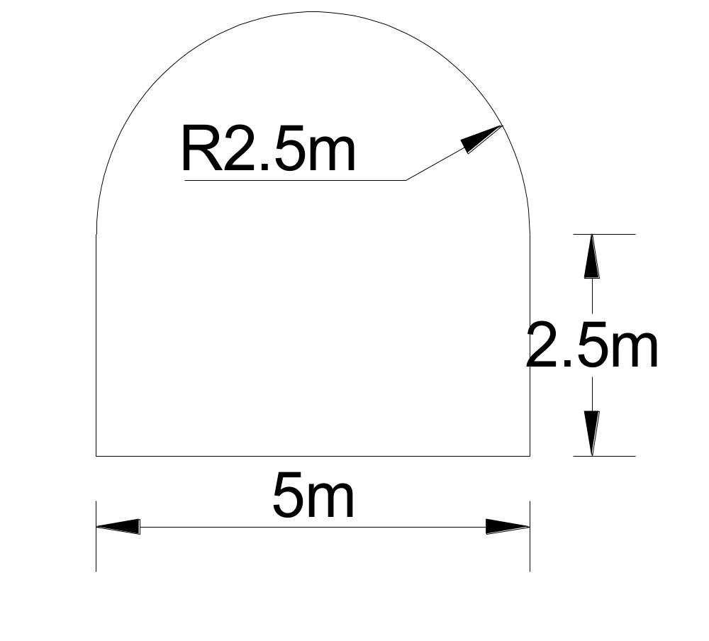
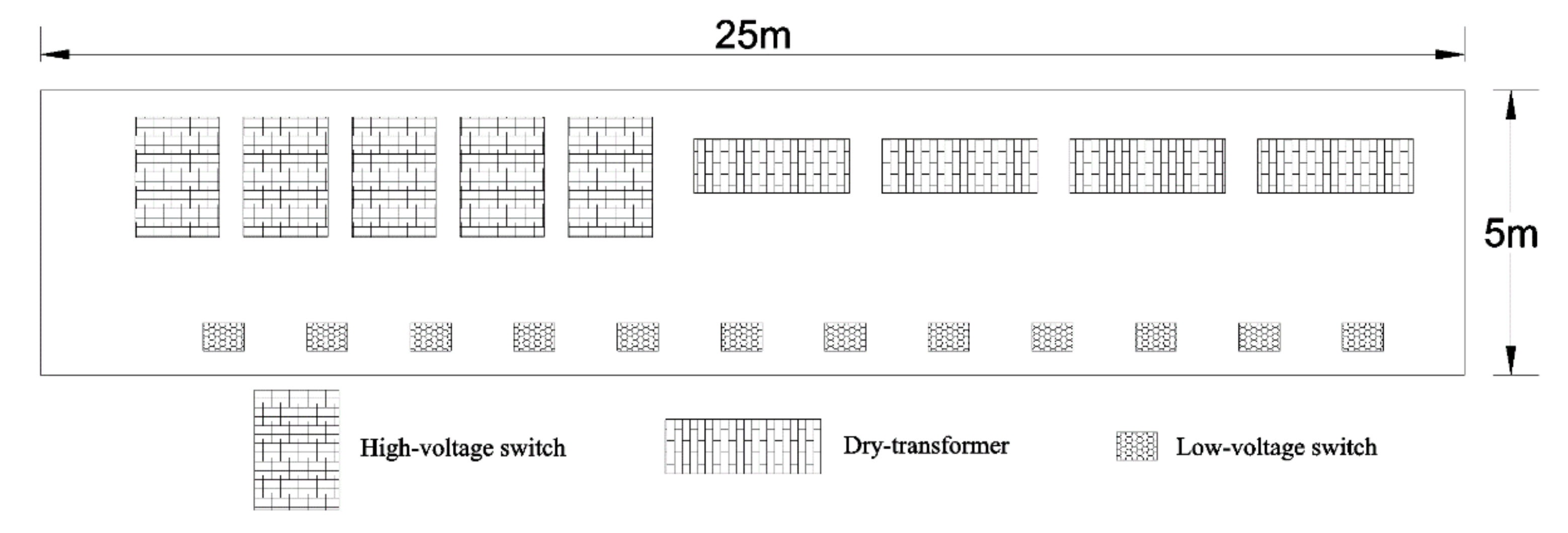
The underground Dongyi substation of Qujiang Mining Company is responsible for the power transformation and power supply of mechanical and electrical equipment in the eastern mining area of the Qujiang Coal Mine. The substation is located in the −850 East Lane of the mine, near the stone door of Dongyi. The surface elevation of Qujiang Company is about +37 m, the floor elevation of the substation is −850 m, and the actual buried depth of the substation is nearly 900 m. Currently, there are several pieces of equipment (4 dry-type transformers, 5 high-voltage distribution switches, and 12 low-voltage distribution switches) in the substation. Because the substation serves as a place for centralized distribution of voltage and current, the room temperature in the substation is stable above 28 °C, due to the high power of transformers and high-voltage switches. Especially because the temperature of the wellhead is high in summer, the highest temperature of poorly ventilated areas can reach up to 38 °C. Because the temperature of the working environment of transformers and high-voltage switches cannot exceed 40 °C, if the ambient temperature always exceeds 35 °C, it will accelerate the aging of the equipment and introduce instability, which will affect normal production. The actual equipment layout inside the substation chamber is shown in Figure 3, the cross-sectional dimensions of the substation chamber are shown in Figure 4, the equipment layout is shown in Figure 5, and the equipment model cross-section dimensions are shown in Table 1.
3.3. Numerical Simulation Model Construction and Simulation Scheme
In order to find an economical and reasonable method to solve the problem of high temperature in the substation, a simulation study of the substation was performed by using the CFD simulation software AutoDesk. According to the data found in the previous literature and field measurements [25], the heat-regulating circle of the surrounding rock of the chamber was about 40 m away from the surface of the chamber, and therefore the size of the simulation model was finally determined as follows: width × height × length: 85 m × 85 m × 25 m. According to the situation of the site, the size of the front and rear air door of the chamber was determined as follows: width × height: 1.6 m × 2 m.
- 1.
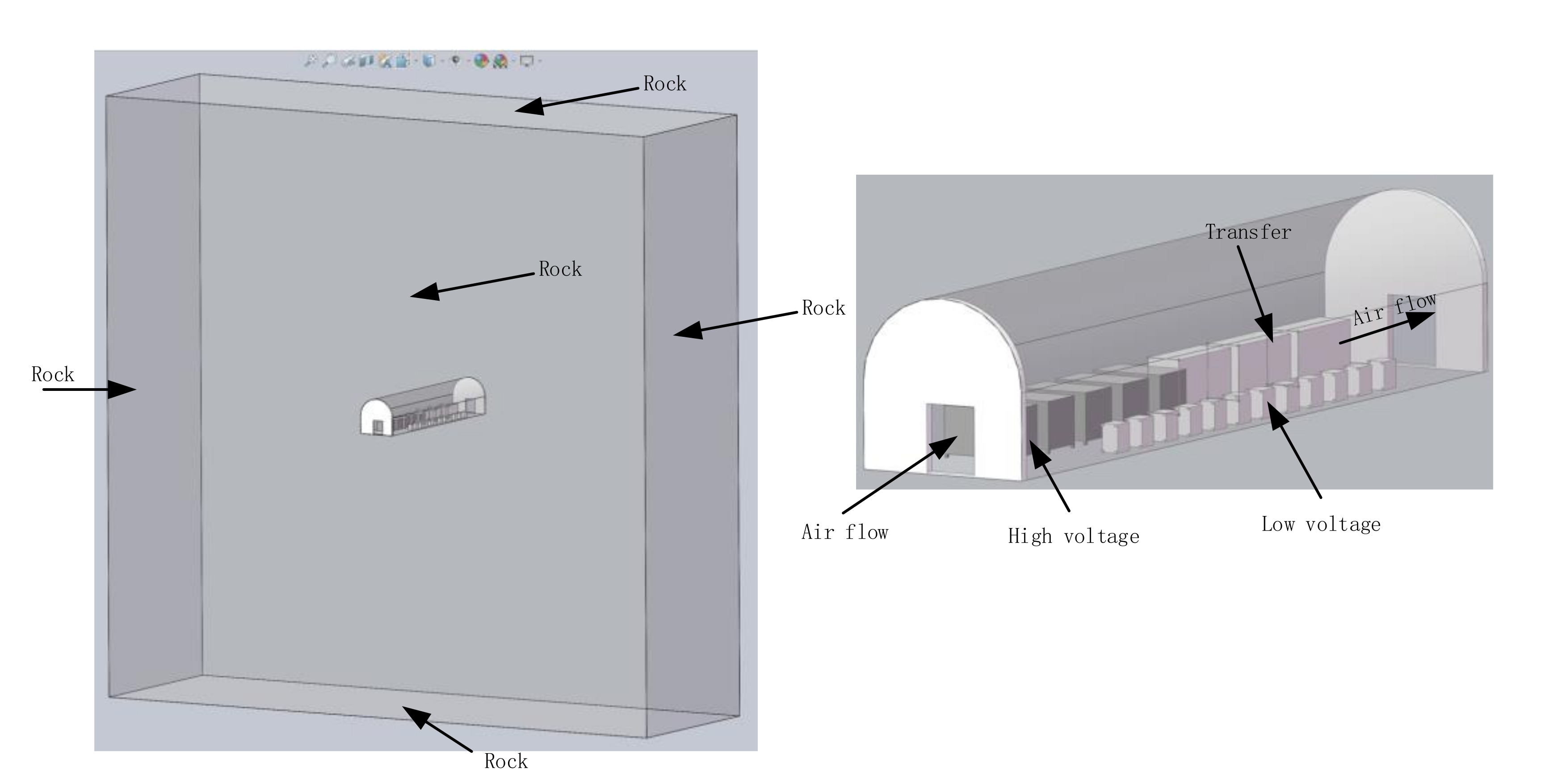
- We created a simulation geometric model: According to the model size parameters of Figure 4 and Figure 5 and Table 1, using Solidworks software, we created a simulated geometric model and saved it, as shown in Figure 6. Then, we imported the created model into CDF software, and set the analysis unit of the model to cm.
- 2.
- We determined the material properties and heat transfer parameter settings of the simulated objects in the model: The surrounding rock was made of solid material. Because the surroundings of the cavern were made of concrete, the model was simplified to a certain extent, and the surrounding area of the cavern was all set to concrete. The surface of the equipment was made of steel material; so, the equipment model was simulated with steel. Air was used for the heat transfer between the chamber periphery and the equipment. The specific heat transfer parameters are shown in Table 2.
- 3.
For the boundary conditions of the model, the boundaries of the surrounding rock where the chamber was located in the original rock temperature (the top, bottom, left, and right sides) of the model were set as follows: static temperature = 40 °C. Because the front of the simulation model was the air inlet roadway, the distribution of the surrounding rock-controlled temperature circle was the same as that in the model, while the back of the model was the air outlet roadway, and the temperature was the same as the temperature of the air outlet. Therefore, we simplified this condition to a certain extent. The heat exchange before, after, and in the model were not considered. The air heat transfer parameters are shown in Table 2. The wind speed was equal to the wind speed set by the simulation scheme, as shown in Table 4.
For the simulation scheme setting, the maximum temperature in summer was simulated with different wind speeds, and the maximum wind speed was set to 6 m/s according to the relevant regulations of the mine [29], to obtain the ventilation condition and optimal equipment layout scheme, which met the high-temperature condition in summer. The boundary condition of the exit of the chamber was: wind pressure = 0 MPa.
- 4.
- We, then, solved the model: The grid division was the automatic grid size division of the material system.
The air turbulence model adopted the K-epsilon model, the heat transfer model adopted forced convection automatically, the gravity direction was the −z direction, and other parameters adopted the default system parameters. The operation model entered a steady-state and ended the operation.
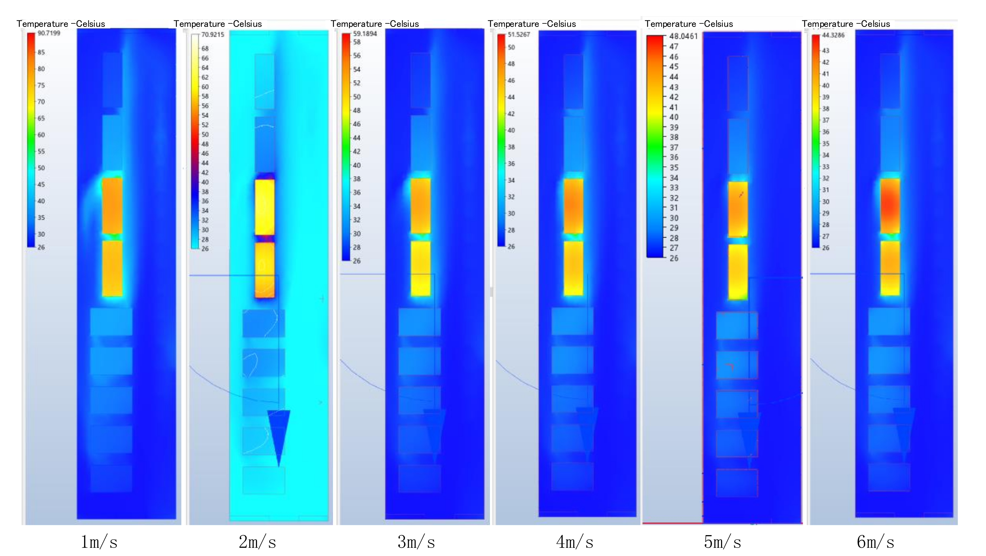
The plane distribution of temperature inside the chamber is shown in Figure 7, after the simulation of different schemes.
The simulation results showed that at an inlet air temperature of 26 °C, the temperature of the transformer gradually increased with the decrease in the inlet wind speed, resulting in a further increase in the air temperature around the transformer in the chamber. At the same time, the simulation results also showed that the simulated wind speed could effectively achieve a cooling effect for both the high-voltage switches and low-voltage switches. The core temperature of the transformer reached 44 °C when the wind speed was 6 m, 47 °C at 5 m, 51 °C at 4 m, and 58 °C at 3 m. The core temperature of the transformer reached 70 °C when the wind speed was 2 m and 90 °C when the wind speed was at 1 m, which is disadvantageous to the stable operation of the equipment. Moreover, because the two working transformers were arranged in front of each other on the wind flow route in the chamber, the wind flow from the latter transformer went through the front transformer, causing a certain increase in temperature, which had a negative impact on the heat dissipation of the latter transformer. Therefore, it was necessary to improve the equipment layout.
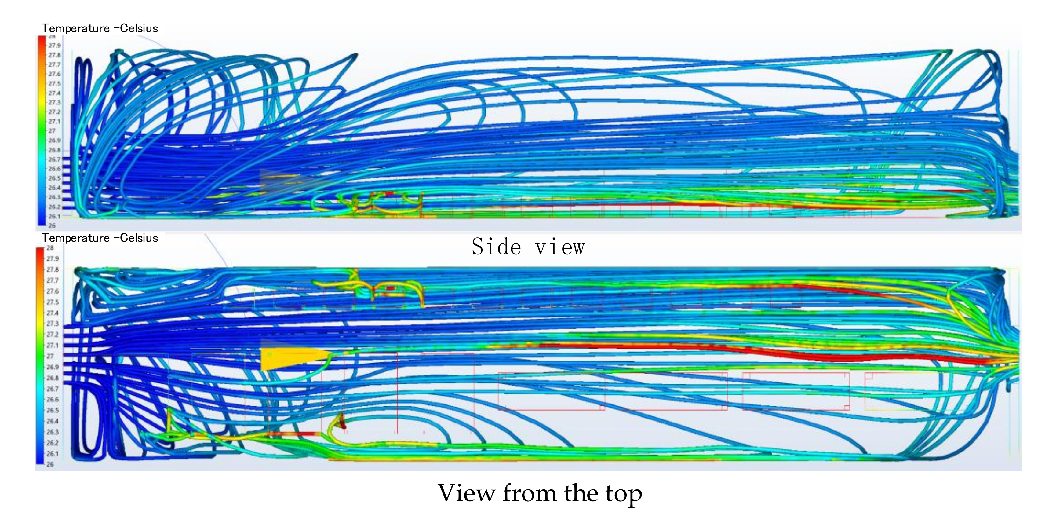
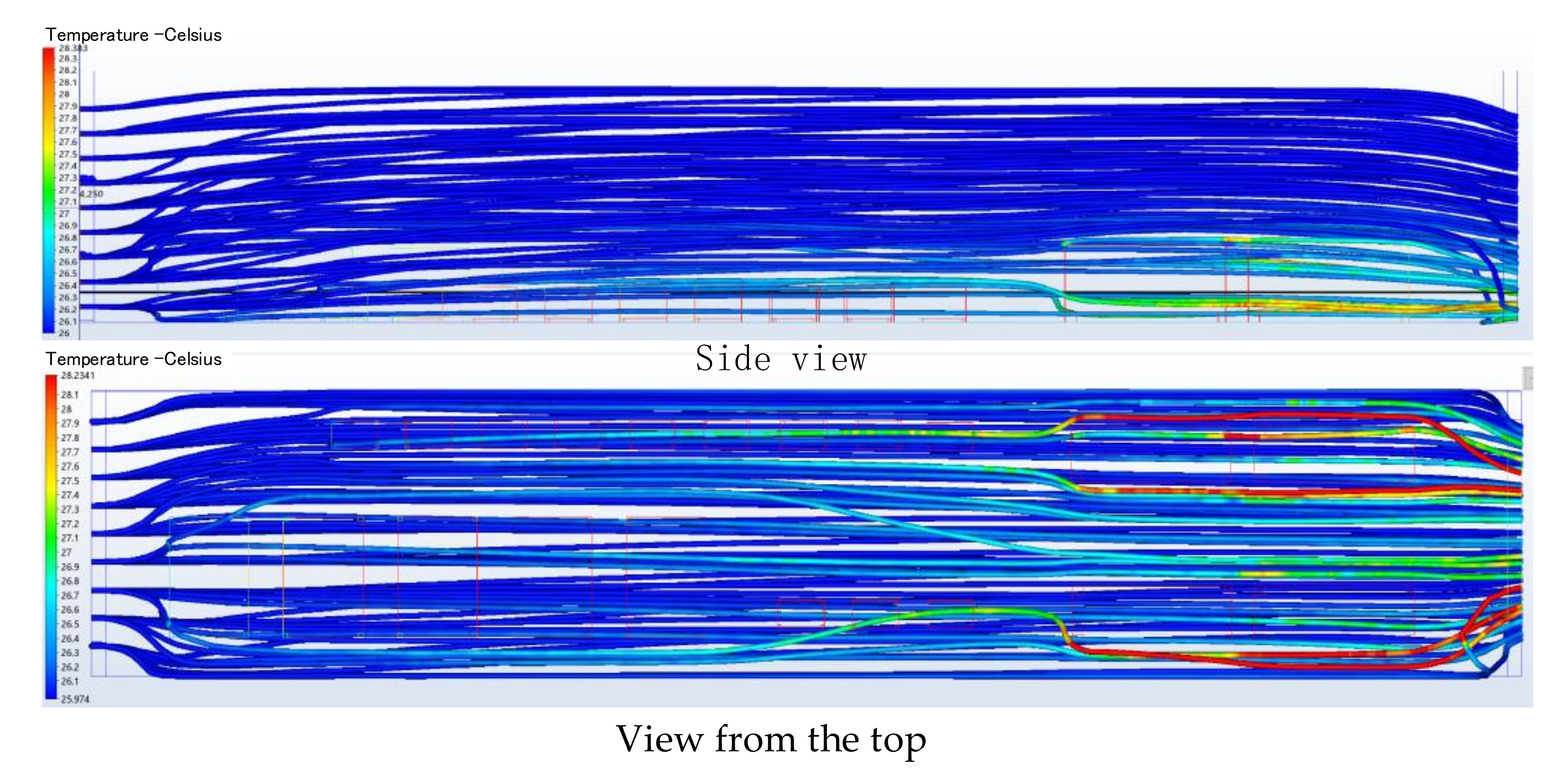
In order to further understand the cooling effect of ventilation in the chamber, a study of the wind flow path was conducted. The simulation results are shown in Figure 8.
The simulation results of the wind flow routes from the side view and the view from the top showed that with the existing equipment layout, due to the small size of the air inlet door, after the wind flow entered the chamber, a wind flow whirl was produced, which increased the length of the wind flow path inside the chamber, thus showing multiple areas of temperature increase, especially behind the substation equipment, where the wind flow’s heat increased significantly. In particular, from the view from the top of the wind flow route, the temperature of multiple areas within the chamber increased, which is detrimental to the long-term operation of the equipment.
4. Proposal for a New Scheme
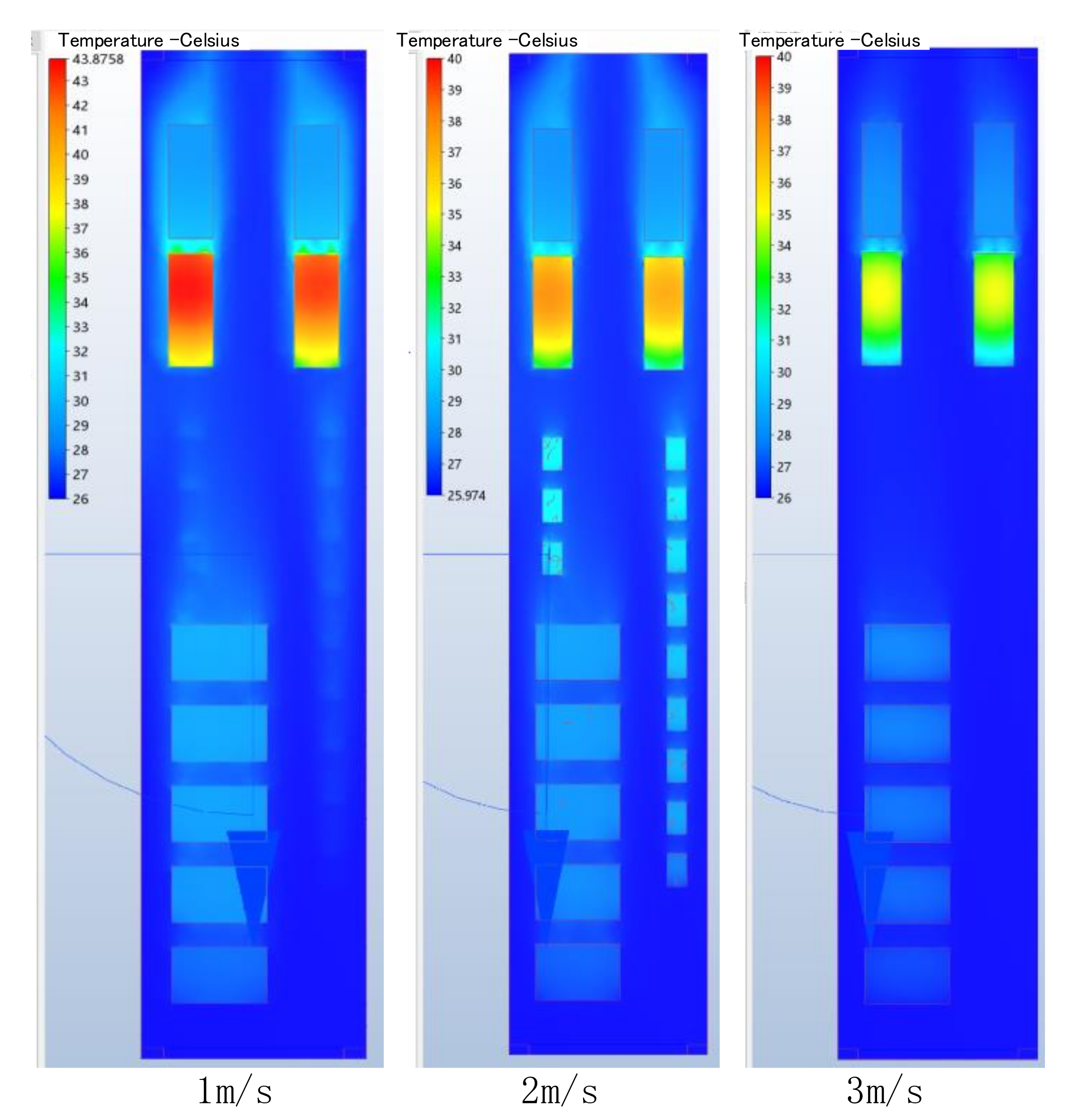
According to the simulation results and the size parameters of the field equipment and the chamber, the four transformers were changed to two on the left and two on the right, one working and one on standby on each side, and three low-voltage switches were moved to the side of the transformer. At the same time, the opening of the front and rear air door were increased to a width of 4 m and a height of 4.3 m with a straight wall arched door. Numerical simulation was performed for the rearranged substation chamber with an inlet air temperature of 26 °C and wind speed of 1 m, 2 m, and 3 m, respectively, as shown in Figure 9.
The chamber temperature distribution of the new scheme under different wind speeds (Figure 10) showed that the maximum temperature of the equipment in the chamber at 1 m/s reached 43 °C, 37.5 °C at 2 m/s, and 35.5 °C at 3 m/s. Therefore, a wind speed of only 2 m/s was sufficient to cool the chamber under the improved scheme. To further validate the ventilation effect of the improved scheme, a simulation of the ventilation route was performed, as shown in Figure 10.
The new scheme significantly reduced the turbulence of the wind flow in the chamber compared to the old scheme, and the temperature rise was mainly concentrated at the tail of the chamber, effectively reducing the high temperature areas.
5. Discussion and Conclusions
There are many heat sources inside the deep substation chamber, and there are many factors affecting the temperature distribution. To ensure good operating conditions for the equipment, not only the ventilation conditions but also the layout of the equipment need to be considered.
- 1.
- The measured data on site showed that the radius of the heat-regulating circle in the deep substation chamber was about 40m and varied little with the seasons.
- 2.
- Due to the limitation of ventilation speed in the deep chamber, in order to ensure the proper operation of the equipment, it was necessary to reasonably arrange the equipment in relation to each other to reduce the interference between the heat-generating equipment, and at the same time, reduce the temperature inside the chamber as much as possible by arranging the heat generating equipment near the exit door of the chamber.
- 3.
- The size of the air door directly affected the turbulence degree of the air flow inside the chamber. The smaller the air door was, the more turbulent the air flow; the longer the wind route was and the larger the air door was, the less turbulent the air flow. In addition, the shorter the air flow route was, the more conducive it was for taking away the heat from the heat source inside the chamber.
Author Contributions
Writing—original draft preparation and software K.H.; project administration, J.Z., writing—review and editing, H.W.; data curation, Q.J. All authors have read and agreed to the published version of the manuscript.
Funding
This research was funded by the National Natural Science Foundation of China, grant number 52074117, 51774133. The APC was funded by the National Natural Science Foundation of China, grant number 52074117, 51774133.
Institutional Review Board Statement
Not applicable.
Informed Consent Statement
Not applicable.
Data Availability Statement
Data available on request due to privacy restrictions.
Conflicts of Interest
The authors declare no conflict of interest.
References
- Chen, G. Study on Cooled Zone Radius and Temperature Distribution Law of Surrounding Rock. Coal Technol. 2014, 33, 113–115. (In Chinese) [Google Scholar]
- Song, D.P.; Zhou, X.H.; Bai, G.; Li, A. Study on temperature field distribution law of surrounding rock in active thermal insulated roadway of high temperature mine. Coal Sci. Technol. 2017, 45, 107–113. (In Chinese) [Google Scholar]
- Zhang, Y.; Xie, Q.; Dong, Z.; Pi, Z. Study on the influence of roadway cross-section shape on heat dissipation of surrounding rock. J. Saf. Environ. 2021, 21, 2595–2601. (In Chinese) [Google Scholar]
- Jiang, T. Temperature Field of the Surrounding Rock and Air Temperature Distribution in Tunnels with High Geothermal Temperature. Master’s Thesis, Dalian University of Technology, Dalian, China, 2020. (In Chinese). [Google Scholar]
- Du, C.; Bian, M.; He, S.; Wang, J. Formulas of Radius and Temperature for Heat-regulating Circle Based on Steady Heat Conduction. Min. Saf. Environ. Prot. 2018, 45, 28–33. (In Chinese) [Google Scholar]
- Han, F. Experimental Study on Similar Simulation of Heat Transfer in Mine Surrounding Rock. Master’s Thesis, Xi’an University of Science and Technology, Xi’an, China, 2018. (In Chinese). [Google Scholar]
- Zhang, N. Research on High-temperature Chamber Cooling System Equipments in Coal Mine. Coal Technol. 2014, 33, 305–307. (In Chinese) [Google Scholar]
- Wan, L.; Chu, Z.; Hu, J. Thermal Environment Analysis of High Temperature Chamber in Yongchuan Coal Mine. Saf. Coal Mines 2014, 45, 163–166. (In Chinese) [Google Scholar]
- Shi, J.; Dong, Z.; Xu, Q. Research on Ventilation Scheme of Substation in Elevated Metro Station. Mod. Transp. Technol. 2017, 14, 81–83. (In Chinese) [Google Scholar]
- Xu, Z. Exploring the Cooling Mode of 500 kV Transformer. Technol. Innov. Appl. 2020, 114–115. [Google Scholar]
- Chen, Y. Exploration on the effect of the chamber enclosure and the absolute heat source of wind flow. Xinjiang Youse Jinshu 1988, 11, 1–7. (In Chinese) [Google Scholar]
- Wang, H.; Zhou, Q. Finite Element Analysis of Surrounding Rock with a Thermal Insulation Layer in a Deep Mine. Math. Probl. Eng. 2020, 2020, 5021853. [Google Scholar] [CrossRef]
- Zheng, Q.; Ke, Y.; Wang, H. Design and evaluation of cooling workwear for miners in hot underground mines using PCMs with different temperatures. Int. J. Occup. Saf. Ergon. 2020, 38, 118–128. [Google Scholar] [CrossRef]
- Li, Z.; Xin, S.; Li, P. Application of Vortex Tube for Local Cooling in High Temperature Mines. 3rd Int. Workshop Mine Hazards Prev. Control. 2013, 94, 426–431. [Google Scholar]
- Wang, B.; Li, Z.; Xin, S. Experiment and Analysis of Compressed Air Evaporative Cooling in Zhaolou Mine. 3rd Int. Workshop Mine Hazards Prev. Control. 2013, 94, 222–227. [Google Scholar]
- Mutama, K.R. Assessing new airflow requirements at the Meikle mine—A case for an additional main centrifugal fan and the inclusion of evaporative cooling spray chambers for airflow quality improvement. Eighth Int. Mine Vent. Congr. 2005, 2005, 481–487. [Google Scholar]
- Du, Y.; Gai, W.M.; Jin, L.Z.; Sheng, W. Thermal comfort model analysis and optimization performance evaluation of a multifunctional ice storage air conditioning system in a confined mine refuge chamber. Energy 2017, 141, 964–974. [Google Scholar] [CrossRef]
- Zhang, Z.; Day, R.; Wang, K.; Wu, H.; Yuan, Y. Thermal performance analysis of an underground closed chamber with human body heat sources under natural convection. Appl. Therm. Eng. 2018, 145, 453–463. [Google Scholar] [CrossRef] [Green Version]
- Zhang, Z.; Wu, H.; Wang, K.; Day, R.; Yuan, Y. Thermal performance of a mine refuge chamber with human body heat sources under ventilation. Appl. Therm. Eng. 2019, 162, 114243. [Google Scholar] [CrossRef]
- Xia, W.; Xie, G.; Pan, D.; Yang, J. Effects of Cooling Conditions on Surface Properties of Heated Coals. Ind. Eng. Chem. Res. 2014, 53, 10810–10813. [Google Scholar] [CrossRef]
- Zhai, X.; Xu, Y.; Yu, Z. Design and Performance Simulation of a Novel Liquid CO2 Cycle Refrigeration System for Heat Hazard Control in Coal Mines. J. Therm. Sci. 2019, 28, 585–595. (In Chinese) [Google Scholar] [CrossRef]
- Wang, Y.; Wang, W.; Han, L.; Zhou, J. Experimental Study on Temperature Distribution Law of Roadway Surrounding Rock Regulating Thermal Circle in High Ground Temperature Mine. China Energy Environ. Prot. 2018, 40, 44–48. [Google Scholar]
- Gao, J.L.; Yang, M. Analysis of the Factors Influencing Temperature Distribution of Surrounding Rock and Cooled Zone Radius. China Saf. Sci. J. 2005, 15, 76–79. (In Chinese) [Google Scholar]
- Zhang, S.; Jia, B. Nemerical Simulation Analysis on Heat Exchange of Wind Current and Surrounding Rock in Heat Harmful Mine. Sci. Technol. Eng. 2006, 6, 3832–3835. (In Chinese) [Google Scholar]
- Yu, H. Geothermal and Heat Damage Management of Mine; China Coal Industry Publishing House: Beijing, China, 1991. (In Chinese) [Google Scholar]
- Zhang, X. Study on the Influence of Atomospheric Pressure Change on Gas Emission in the Goaf of Laohutai Mine and Its Prevention and Control Technology. Ph.D. Thesis, China University of Mining and Technology, Xuzhou, China, 2020. (In Chinese). [Google Scholar]
- Ji, J. Study on the Heat Transfer and Heat Harm Control of Driving Face in Deep Mine. Ph.D. Thesis, Chongqing University, Chongqing, China, 2014. (In Chinese). [Google Scholar]
- Ji, J. Study on Heat Dissipation of Surrounding Rock in Heat Damage Mine; Coal Industry Press: Beijing, China, 2010; pp. 552–556. (In Chinese) [Google Scholar]
- Zhou, C. Research of Key Technologies of High Precision and Low Limit Ultrasonic Wind Speed and Direction Sensor; China Coal Research Institute: Beijing, China, 2018. (In Chinese) [Google Scholar]
Figure 1.
Schematic diagram of temperature measurement and drilling equipment layout.

Figure 2.
Temperature curve within surrounding rock of chamber.

Figure 3.
Physical diagram of the substation.

Figure 4.
Cross-section of the substation.

Figure 5.
Substation equipment layout plan.

Figure 6.
Schematic diagram of the simulation model.

Figure 7.
Comparative diagram of temperature distribution within the chamber of different schemes.

Figure 8.
Wind flow routes of different schemes.

Figure 9.
Comparison of simulation results of different wind speeds of the new scheme.

Figure 10.
Wind flow route of the new scheme.


Table 1.
Substation equipment model and size table.
| Name | Model | Equipment Power/W | Size (Length × Width × Height)/mm | Quantity/ Set |
|---|---|---|---|---|
| Dry-type Transformer | KBSG-315/66/0.69 | 1300/2500 | 2800 × 980 × 1555 | 4 |
| High-voltage Switch | QKBG-1000/10-250 | 1000 | 2113 × 1476 × 1390 | 5 |
| Low-voltage Switch | KBZ2-400(200)/660 | 200 | 718 × 490 × 814 | 12 |
Table 2.
Heat transfer parameters of concrete and equipment.
| Parameters | Concrete | Steel | Air |
|---|---|---|---|
| Thermal Conductivity | 0.011 W/cm/K | 0.54 W/cm/K | 0.0002563 W/cm/K |
| Density | 2.306 g/cm³ | 7.833 g/cm³ | system default |
| Specific Heat | 0.837 J/g/k | 0.465 J/g/k | 1.004 J/g/k |
| Emissivity | 0.92 | 0.3 | 1 |
Table 3.
Total heat of equipment.
| Name | Equipment Power | Quantity | Remark |
|---|---|---|---|
| Transformer | 2000w | 2 sets | 2 in use and 2 as alternates |
| High-voltage switch | 300w | 3 sets | 3 in use and 1 as alternate |
| Low-voltage switch | 100w | 12 sets | - |
Table 4.
Simulation scheme parameter table.
| Scheme | Wind Speed | Entrance Temperature | Scheme | Wind Speed | Entrance Temperature |
|---|---|---|---|---|---|
| 1 | 1 m/s | 26 | 4 | 4 m/s | 26 |
| 2 | 2 m/s | 26 | 5 | 5 m/s | 26 |
| 3 | 3 m/s | 26 | 6 | 6 m/s | 26 |
Publisher’s Note: MDPI stays neutral with regard to jurisdictional claims in published maps and institutional affiliations. |
© 2022 by the authors. Licensee MDPI, Basel, Switzerland. This article is an open access article distributed under the terms and conditions of the Creative Commons Attribution (CC BY) license (https://creativecommons.org/licenses/by/4.0/).
Share and Cite
MDPI and ACS Style
Hu, K.; Zheng, J.; Wu, H.; Jia, Q. Temperature Distribution and Equipment Layout in a Deep Chamber: A Case Study of a Coal Mine Substation. Sustainability 2022, 14, 3852. https://doi.org/10.3390/su14073852
AMA Style
Hu K, Zheng J, Wu H, Jia Q. Temperature Distribution and Equipment Layout in a Deep Chamber: A Case Study of a Coal Mine Substation. Sustainability. 2022; 14(7):3852. https://doi.org/10.3390/su14073852
Chicago/Turabian StyleHu, Kaiwen, Jian Zheng, Hai Wu, and Qian Jia. 2022. "Temperature Distribution and Equipment Layout in a Deep Chamber: A Case Study of a Coal Mine Substation" Sustainability 14, no. 7: 3852. https://doi.org/10.3390/su14073852
Note that from the first issue of 2016, this journal uses article numbers instead of page numbers. See further details here.