
A Conceptual Framework for Estimating Building Embodied Carbon Based on Digital Twin Technology and Life Cycle Assessment


1
Department of Structural Engineering, College of Civil Engineering, Tongji University, Shanghai 200092, China
2
School of Civil & Environmental Engineering, Nanyang Technological University, Singapore 639798, Singapore
*
Author to whom correspondence should be addressed.
Sustainability 2021, 13(24), 13875; https://doi.org/10.3390/su132413875
Submission received: 11 October 2021
/
Revised: 27 November 2021
/
Accepted: 6 December 2021
/
Published: 15 December 2021
Abstract
:Low-carbon building design requests an estimation of total embodied carbon as the environmental performance metric for comparison of different design options in early design stages. Due to a lack of consensus on the system boundaries in building life cycle assessment (LCA), the carbon estimation results obtained by the current methods are often disputable. In this regard, this paper proposes a method for estimating building embodied carbon based on digital twin technology and LCA. The proposed method is advantageous over others by providing (1) a cradle-to-cradle LCA and (2) an automated data communication between LCA and building information modelling (BIM) databases. Because data for the processes in the life cycle are collected via digital twin technology in a standard and consistent way, the obtained results will be considered credible. So far, a conceptual framework is developed based on a comprehensive literature review, which consists of three parts. In the first part, formulas for LCA are given. In the second part, a hybrid approach combining semantic web with a relational database for BIM and radio-frequency identification (RFID) integration is described. In the third part, how to design the LCA database and how to link LCA with BIM are described. The conceptual framework proposed is tested for its reasonableness by a small hypothetical case study.
1. Introduction
Carbon dioxide (CO2) is a key greenhouse gas that drives global climate change. Being the largest emitter of CO2 in the world, China has faced widespread criticism from the international community. To demonstrate China’s role as a responsible country in the international system, Chinese President Xi Jinping has pledged that the nation would achieve carbon neutrality by 2060 and reach CO2 emissions peak before 2030. The building sector is the contributor to more CO2 emissions than any other sector in the country—more than transportation, agriculture, and industry. According to the China Building Energy Consumption Research Report [1], the total carbon emission from the whole process of construction in China in 2018 reached 4.93 billion tons, accounting for 51.3% of the country’s total emissions. Thus, the architecture, engineering, and construction (AEC) industry is the focal point for industry decarbonization.
In the path to net-zero emissions and limiting global warming, the first step for the industrial stakeholders to understand their carbon reduction potential is to identify and measure where their emissions come from. Emissions generated during the life cycle of a building are generally put into two groups: operational emissions and embodied emissions. Operational carbon emissions are caused by using energy to heat, cool, and power a building, while embodied carbon emissions are associated with building materials across the life. Unlike operational carbon, which can be gradually reduced over time by using renewable and clean energies, embodied carbon is locked in place once a building is built. Hence, the only way to reduce the total embodied impact of a building is to select low-carbon materials and products at the early design stages [2].
In the past several decades, reducing operational carbon has been the focal point. With the decrease in operational carbon, the focus now shifts to reducing embodied carbon because it also contributes a large portion of a building’s total carbon footprint. Whole-life embodied carbon is associated with energy consumption and chemical processes during the extraction, manufacture, transportation, assembly, replacement, and deconstruction of building materials [3]. Life cycle assessment (LCA) is the popularly used method for embodied carbon measurement [4,5]. The system boundary limits of LCAs can vary considerably in different studies, such as different life cycle stages, e.g., cradle-to-gate [6] and cradle-to-cradle [7]; different building types, e.g., low-rise buildings [8] and high-rise buildings [9]; as well as different material quantification scopes, e.g., structural materials and finishing materials [10], building materials that were included in the structure and envelop [7]. Because studies often choose a system boundary subjectively, results of such studies may not be comparative.
There are many important regulations and standards for embodied carbon assessment of buildings and infrastructure assets worldwide, in light of the need to tackle embodied carbon to stay within the carbon budget. The Journal of The American Institute of Architects [11] summarized 34 regulations and standards prevailing in western countries. China also published several regulations and standards, including “Regulation on Energy Conservation in Civil Buildings” in 2008, “Standard for Sustainability Assessment of Building Project” in 2012, and “Standard for Measuring, Accounting and Reporting of Carbon Emission from Buildings” in 2014. Nevertheless, a fact behind the growing number of rules and methodologies for quantifying whole-life embodied carbon is the lack of consensus on exactly how it should be defined and calculated. To enable meaningful comparisons between different structural schemes, it is recommended that the calculation of embodied carbon follows the same rigorous way across all designs [12]. However, undertaking assessment for embodied carbon is not as straightforward as assessment for operational carbon, which is relatively simple to extrapolate from occupants’ energy bills. Without agreed rules, data, and data structures, significant inconsistency can occur, leading to wrong beliefs.
Building information modeling (BIM) is a digital representation of a building. BIM is likely to provide a robust data foundation for quantifying the carbon footprint. Over the years, BIM and its beneficial relationship with sustainable and sustainability, green buildings, and life cycle assessment have been well established in the literature. Several BIM-based carbon calculators have already been released, such as the AutoBIM Carbon Calculator developed by Balfour Beatty, the AI-based Embodied Carbon Calculator by Costain-Winvic, the Structural Carbon Tool developed by Elliott Wood and the Institution of Structural Engineers, and in China, the Life Cycle Building Carbon Calculator developed by PKPM technology. However, BIM itself can only provide static information. The need of linking real-time data with BIM is identified based on the requirements of cradle-to-cradle LCA, which considers the scheduled and unscheduled maintenance, repair, replacement, and refurbishment events in the use stage. Therefore, rather than BIM, this study proposes the use of a BIM-based digital twin. A BIM-based digital twin is the integration of real-time sensing data and the static information provided by BIM.
Despite the increasing adoption of the digital twin in the manufacturing industry [13], safety domain [14,15], and occupational health [16], the application of digital twins in the building sector is still in its infancy [17,18]. When BIM meets the Internet of Things (IoT), interoperability is the main challenge. This paper thereby proposes an industry foundation classes (IFC)-based data integration approach for the contextual information (BIM data) and timeseries (sensor collected) data, which is considered robust for interoperability and automation. A radio-frequency identification (RFID)-based digital twin platform is designed for real-time asset tracking in construction and the built environment. Based on the RFID-based digital twin, the paper proposes an effective method for efficient whole-life embodied carbon assessment for buildings. The design of the LCA database is compatible with the granularity of the BIM model, facilitating a two-way automatic data exchange between the two databases.
Assessing the total embodied carbon of the building is most useful in the early design stages when large-scale design improvement opportunities exist. Because detailed information about buildings is not available yet at this time, generic data are used. Generic data are created based on similar designs of sample projects of similar building types. There is a multitude of design options. Therefore, a fast method is needed to evaluate different design options to facilitate decision making. The BIM-based LCA system designed in this work can satisfy the need by offering a fully automated tool. The common data structure and naming convention proposed in the LCA database and BIM model can promote the establishment of standardized data collection and data entry among different stakeholders in the value chain, which ensures the data consistency in heterogeneous systems as well as at the different levels of development. At last, the method is considered reliable for its data quality. The ultimate outputs from this work will include not only a total embodied carbon estimation tool for buildings but also a public database that can be commonly shared in the AEC industry for carbon assessment practice.
The remainder of the paper is structured as follows: Section 2 explains the research methodology. Section 3 presents the comprehensive review of the related literature. Section 4 describes the conceptual framework of the digital-twin-based LCA for measuring building embodied carbon. Section 5 tests the proposed conceptual framework for its reasonableness by a small hypothetical case study. Section 6 makes further discussions. Finally, the paper is concluded with suggestions for future research in Section 7.
2. Research Methodology
To ensure a comprehensive review, the review of the literature was conducted in three areas: (1) existing life cycle embodied carbon emission calculation methods; (2) current integration of BIM and LCA in buildings; (3) digital twin use cases and applications in the AEC industry. The search methodology is presented in Table 1. The authors found 450 papers from the search. Finally, 54 of the most relevant papers as summarized in Table 2 were selected for a detailed analysis by analyzing the title, abstract, keywords, paper contents, and journal’s main topic of interest.
The literature review was guided by the following questions:
- What are the future research directions in LCA?
- What is the best communication method between BIM and LCA databases?
- What is the best storage method for big data in different formats and how to query information?
This study attempts to propose a good method for estimating building embodied carbon from the answers to these research questions.
3. Review of the Literature
3.1. Life Cycle Embodied Carbon
Two main methods—the process-based (i.e., the bottom-up) and input–output analyses (i.e., the top-down)—are widely used in the LCA building emissions [4,19]. In the process-based methods, the emission amount is expressed as the multiplication of material quantity and embodied carbon factor (ECF), whereas, in the input–output method, the emission amount is expressed as the multiplication of cost and intensity. Nevertheless, both methods have limitations. Process-based methods involve truncation errors that are likely to underestimate emissions, while input–output-based methods lack specificity. The substantial disparity in carbon figures was found in the same project case using the two methods [20]. Therefore, many researchers seek a more efficient method by hybridizing the previous two. The hybrid one can be process-based [19], input–output-based [21], or integrated [22], depending on its calculation frameworks and the type of data used.
The conventional LCA is static. Towards a whole-life cycle assessment, dynamic LCA (DLCA) is recommended. DLCA can cover the dynamic factors and their interaction with embodied carbon to obtain a better understanding of the environmental performance in the building usage stage. Kang et al. [23] used system dynamics for DLCA simulations to study recurrent embodied impacts caused by maintenance and repair activities. Resch et al. [24] proposed a DLCA model in which future emissions are represented by a random variable and adjusted by time-varying weighing functions, which indicate the effects of technological progress and climate change over a time horizon.
The biggest challenge of conducting LCA is associated with data collection [25]. The process-based methods need several iterations of data collection from the data sources that are commonly distributed among several individual sub-contractors [26], and the input–output methods rely on national data, which in most countries such as China, the classification of sectors is too coarse to target a specific product [19]. As a result, deriving useful results under the circumstances of limited data availability attracts interest from researchers. For example, Gardezi et al. [6] developed a statistical technique of multivariable regression analysis for the prediction of embodied carbon in conventionally constructed housing units. Yeo et al. [25] proposed a streamlined technique that comprises a probabilistic model of emission factor estimators that are used to estimate the required embodied carbon. However, so far, there is no best method because every model has a different set of assumptions caused by uncertainties that affect the accuracy of the outcome. There is still a lot of work to be done to achieve a standardized method.
After quantifying the amount of embodied carbon emissions of buildings, the concern is then to reduce them. The greatest opportunity to reduce them comes at the design phase [3]. Researchers have found the choice of housing typologies, construction process, building shape, and building materials influence life cycle carbon emissions [26,27]. Low-energy and zero-emission building design can be found by conducting a comparative analysis of different design options. However, without a robust method, results from comparisons may not be credible. Many researchers [28,29] demonstrated that some technologies can significantly increase the embodied carbon impact of modern low to zero energy buildings. In this regard, Pomponi and Moncaster [30] appealed that both greater transparency and greater conformity must be embraced industry wide. Wolf et al. [31] pointed out the necessity of establishing a public accessible benchmarking database of embodied quantity outputs for building structures.
BIM gives opportunities to increase the data transparency and compliance check and to automate the LCA assessment process. The capability of BIM to include details of individual suppliers facilitates such product-specific databases that have accurate information on the impact of material sourced from a specific supplier, which in turn promotes the use of consistent methods to determine the embodied energy of their materials among suppliers [32]. In the end, BIM–LCA integration is expected to play a significant role in carbon quantification and mitigation in the future.
3.2. BIM–LCA Integration
LCA is a technique for assessing the environmental aspects and potential impacts associated with a product. The LCA methodology in all sectors follows the four-stage framework recommended by ISO 14040 and ISO 14044. The four stages are (1) goals and scope definition; (2) life cycle inventory (LCI); (3) life cycle impact assessment (LCIA); (4) interpretation. Generally, reliable LCA requires the use of a reliable LCI. As LCA results vary a lot due to distinct regional characteristics, the LCI database is usually developed with regional characteristics in a specific country or territory [33]. Sometimes, due to the lack of local or regional databases, the use of a generic database based on foreign LCI databases is also quite common [34].
The capabilities of BIM bring four main benefits within the LCA applications: (1) to avoid manual data re-entry; (2) to allow real-time assessment; (3) to enhance whole-building appraisals; (4) to implement user-friendly analysis interfaces [32]. Because of these benefits, the integration of BIM and LCA is growing [33,35,36,37,38,39,40].
There are various approaches to integrating BIM–LCA. In summary, BIM is either used to extract quantities to establish the LCI for LCA software or upgraded to 6D BIM to enable LCA analysis [41]. Obrecht et al. [42] reviewed several studies that have classified them. In the most comprehensive classification, they are divided into five types. In the first and second types, BIM data are directly exported to other LCA tools through bill of quantities or IFC files. In the third type, BIM data are processed in a BIM viewer before sending to LCA tools. In the fourth type, LCA plug-ins are developed in BIM software. Additionally, in the fifth type, LCA information is attached to BIM objects. Further, Safari and Jafari [43], based on how the data are collected and used as well as the process of data exchange and type of computation, classified the integration approaches into three types: conventional, static, and dynamic. The conventional approach extracts the data from BIM in the form of an Excel file and manually enters the data into LCA tools. The static approach applies a semi-automated method by creating a plugin in the BIM software and streamlines the data transfer from BIM to LCA with the IFC format. Finally, the dynamic approach, which corresponds to the fifth type in the previous classification, enables two-way automatic communication between BIM databases and LCA databases (i.e., LCI databases) to account for temporal variations. According to the survey [44], the lack of interoperability between LCA and BIM tools is currently the greatest difficulty faced by BIM-based LCAs. Although the existing IFC schema already contains mostly of the necessary properties, no IFC classes for deconstruction exist. Hence, for a complete LCA, it still requires a considerable improvement for encoding BIM classes adaptable to LCA databases [45].
LCA is most valuable in the early design stages because at the end of the design phases, conducting an LCA for assessing different design options becomes not quite useful when the most important decisions are already made and the large-scale design improvement opportunities are lost [43]. However, the level of development (LoD) of the BIM model is not sufficiently high for a detailed LCA in the early stages of design. Hence, where actual data are not available, genetic data are used based on post-completion information of similar building types [46]. While choosing, there are many design options. This brings out a research question about how to assess various design options in a fast way.
Many generic LCA databases are compiling direct data surveyed in a specific region (e.g., ICE database, Ecoinvent database, etc.). The AEC industry also widely adopts environmental product declarations (EPDs) as a method of reporting and sharing environmental data. However, the available LCA data usually refers to cradle-to-gate emissions and are at the material level. Therefore, an entire LCA database that is matched to the asset hierarchy classification within the BIM model is expected. Researchers suggested developing the data structure of the LCA database following the granularity of the BIM model, meanwhile directing towards the automatic compilation of data exchange by using a common naming of elements [43,47,48,49]. Cavalliere et al. [50] suggested using different LCA databases with different levels of details for the specific LoD of the BIM. Since different building elements may not be modelled with identical LoDs, one can mix the LCA databases for building parts and materials with different LoDs and match them according to the individual LoDs of the various BIM components.
3.3. Digital Twin in the AEC Industry
From a static BIM to a web-based digital twin, Deng et al. [51] developed a five-level ladder taxonomy. The five levels are Level 1—BIM; Level 2—BIM-supported simulations; Level 3—BIM integrated with IoT; Level 4—BIM integrated with AI for predictions; Level 5—ideal digital twins, including not only real-time visualization and prediction but also automatic feedback and control of the built environment. However, a smooth upgrade path from a lower level to higher one does not exist. The major challenge is interoperability because IFC is a static data format, which poorly supports the dynamic data update, and IFC lacks a rich vocabulary for describing different sensors, though the IFC schema is constantly evolving [52,53]. The recent IFC4 edition allows for a sensor to be defined using IfcSensor. In total, 23 predefined object types for sensors are available in IFC including a CO2 sensor and movement sensor [54]. For non-predefined sensors, the ambiguity problem may arise using the user-defined way.
It is found in the literature that the BIM data and sensor collected data can be integrated in several ways. A widely adopted approach is to use existing BIM tools’ application programming interfaces (APIs) (e.g., Revit DB Link, Dynamo, Grasshopper) and relational database (e.g., SQL server database, Microsoft Access). Such an approach is suitable for small-scale problems with less complex BIM models and a limited number of sensors. Another approach is to transform BIM data into a relational database using a new data schema. Sensor data can be linked to BIM through SQL queries. This approach is more flexible for large-scale problems with more complicated spatial contexts and a large number of sensors. The third approach is to use a new query language rather than SQL to query sensor data over BIM models or IFC models. This approach can be applied to various kinds of projects. However, new query languages may not gain widespread acceptance. The fourth approach is to use semantic web technologies by linking BIM ontologies (e.g., IfcOWL) and ontologies in the sensor devices domain (e.g., semantic sensor network (SSN)). Building context data representing in IFC are first converted into resource description format (RDF). All sensor data are also expressed in RDF. The standard query language and protocol for linked open data and RDF databases—SPARQL—are implemented to query RDF data. This approach is useful in the case involving various heterogeneous data sources. The last approach is a hybrid one that combines a semantic web with a relational database. Contextual information, such as building context data, sensor information, and other building information are represented in RDF format using the semantic web, while sensor collected timeseries data are retained in the relational database. They can be linked either using ontology or directly using standardized naming formats [55]. As this approach is suitable for different kinds of projects, it is the most promising approach to facilitate IoT deployment in the AEC industry [56,57].
Digital twins in construction heavily focused on the design and engineering phase, while neglecting the demolition and recovery phase [18]. It is possible to add a layer of information to each BIM object to prepare them for future end-of-life applications [58]. The existing literature on digital twins is primarily model based [59]. There is no consensus on specific technical components, protocols, or tools to create a digital twin [60]. Usually, RFID sensors are used for asset tracking. Global positioning system (GPS) technologies are often used for outdoor tracking applications [55], while indoor tracking applications rely upon radio frequency technologies, for example, ultra-wide band (UWB), Wi-Fi, Bluetooth low energy (BLE), Zigbee, and others [61].
3.4. Contributions of the Proposed Work
The contributions of this work are summarized as follows: (1) A novel digital-twin-based LCA approach for measuring embodied carbons of buildings is proposed, which extends the current LCA from partial life cycle to a whole-life cycle. (2) An aggregated data structure design of the LCA database, which follows the granularity of the BIM model, is proposed, facilitating a two-way automatic data exchange between the two databases to enable fast assessment of total embodied impact of the building for different design options in early design stages. (3) A consistent definition and decomposition method for building parts is proposed, which helps standardize the data collection and data entry process among different stakeholders in the value chain to ensure and sustain data quality in the system. (4) A new application instance of digital twin in the AEC industry is provided, which may create opportunities for the uptake and use of digital technologies in the domain.
4. Proposed Framework
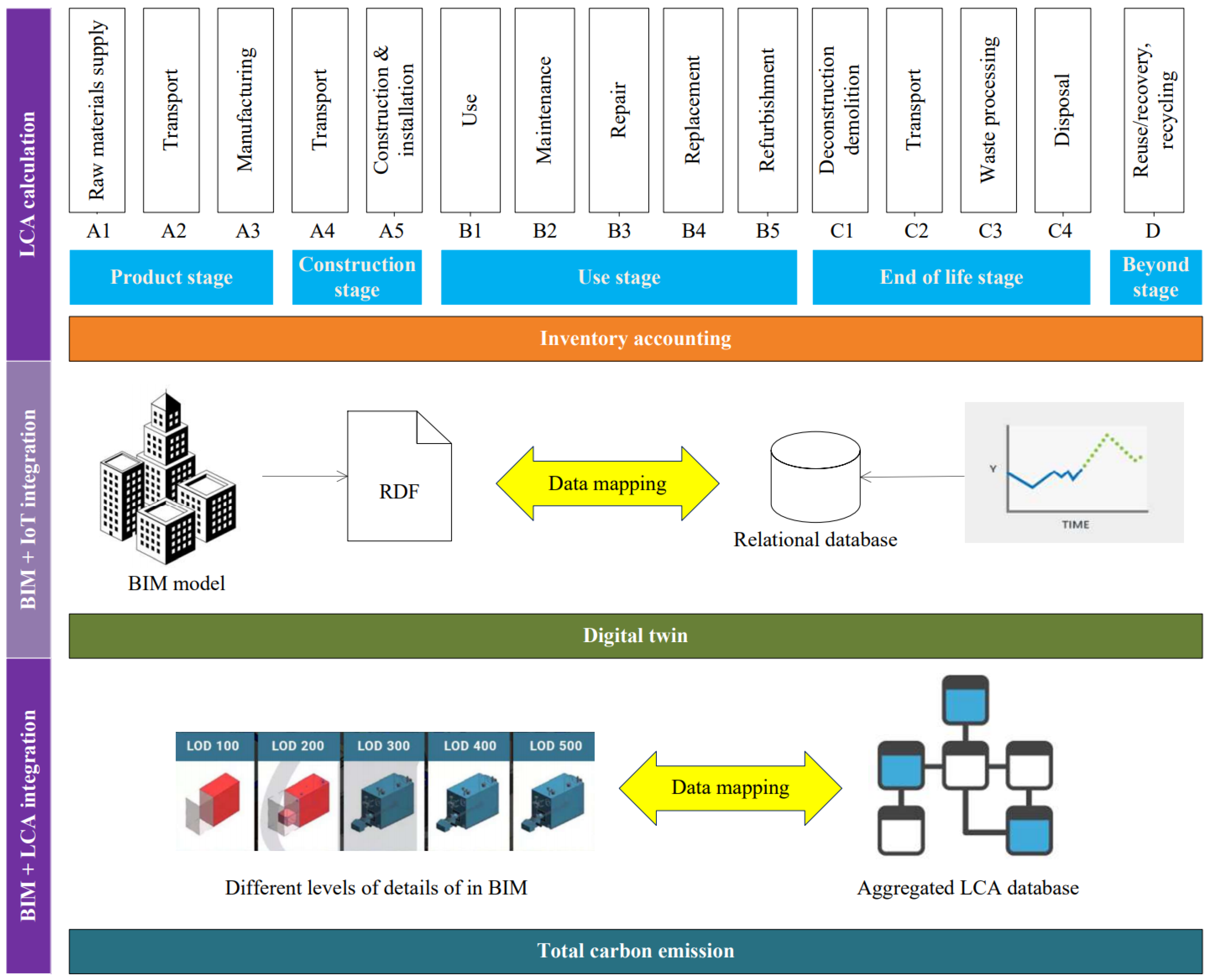
The scope of the current paper is limited to the estimation of the embodied carbon of buildings. LCA scope is cradle-to-cradle, following BS EN 15978 life cycle stages [12]. Figure 1 shows the proposed framework, which comprises three parts: LCA calculation, BIM and IoT integration, and BIM and LCA integration.
4.1. LCA Calculation
The study adopts a process-based method to determine the embodied carbon estimations during the entire life cycle. This study summarizes the exact equations used for detailed calculation procedures in life cycle stages, which are ignored in previous works. The material quantities may be expressed in mass, volume, or area, depending on the ease of measurement. The ECFs tally with these units. The system boundary is known as “cradle to cradle”, which includes the production stage, the construction stage, the use stage, the end-of-life stage, and the beyond (reuse/recovery, and recycle) stage. Each macro stage can be further divided into subsections. The total amount of embodied carbon of a building (Eemb) is calculated by the sum of carbon emissions in each stage, see Equation (1):
4.1.1. Product Stage
In this stage, raw materials are processed, and building materials (including precast and prefabricated products) are manufactured. The emissions primarily originate from chemical reactions and energy consumptions (e.g., diesel, gasoline, and electricity) in the process of producing a finished product from the raw materials (i.e., secondary production). The common building products are made of concrete, steel, blockwork, brick, stone, timber, aluminum, glass, plasterboard, or intumescent paint. The total amount of carbon emissions associated with the product stage (Epro) is calculated by Equations (2) and (3):
where i refers to the type of building material (product), j refers to the type of raw material, k refers to the type of machinery, and l refers to the type of energy. The three items in Equation (3) represent emissions from raw materials, machinery operation, and energy consumption, respectively.
4.1.2. Construction Stage
Carbon emissions from the construction stage are associated with transporting materials (products) and construction equipment to site, materials (products) wasted on-site, and energy used due to construction activity (e.g., energy use of machinery and temporary site offices), as shown in Equation (4):
First, the amount of transportation carbon emissions (EA4) from the factory to the site is calculated by Equations (5) and (6):
where i refers to the type of building material (product) or construction equipment. j refers to the type of transport mode (e.g., road, sea, air, rail).
Then, the amount of carbon emissions associated with the volume of each type of building material (product) that is wasted on site during construction (EA5W) is calculated by Equations (7)–(9):
where i refers to the type of material (product). In Equation (8), the item (WFi × Qi) refers to the quantity of the surplus (i.e., waste). In Equation (9), the item (ECFA13,i + ECFA4,i) refers to the cradle-to-site ECF, the item (ECFC2,i + ECFC3,i + ECFC4,i) refers to the relevant end-of-life ECF, and the item (ECFD,i) refers to the ECF associated with the reuse and recycling process. Depending on different disposal scenarios and kinds of site wastes, different subsections are involved (see Table 3), corresponding to different selections of items in Equation (9).
Last, the total site activity emissions (EA5a) is calculated by Equation (10):
involving the on-site machinery use and energy consumption. It should be noted that EA5a is obtained using a lump sum calculation from the actual machine running times and power bills. There is no need to find one-by-one correspondence to the specific type of building material (or product) for the ease of data collection.
4.1.3. Use Stage
Carbon emissions in the use stage depend on the lifespan of the building. Usually, the reference study period (RSP) of building projects is assumed to be 60 years. The amount of carbon emissions in the use stage () is calculated by the sum of emissions of each subsection, see Equation (11):
First, material surfaces can absorb or release CO2 during a building’s life cycle. The amount of carbon emissions in use () is usually a small percentage (e.g., 2.5%) of the embodied carbon in the product stage.
Then, the amount of carbon emissions from recurrent maintenance activities () and accidental damage repairs () is calculated by Equations (12)–(14):
where refers to the maintenance intervention repair instances in [B2] or repair instances in [B3], refers to the type of repair technique, and refers to the type of repair material (product). refers to the embodied carbon expenditure for the th maintenance intervention. The item refers to the cradle-to-site ECF.
Next, the amount of carbon emissions associated with replacement of building components during a building’s life span () is calculated by Equations (15) and (16):
where refers to the type of building component. means rounding up the value of to its next integer, which refers to the number of times a component is replaced during a building’s life. represents the cradle-to-cradle ECF except the use stage.
Finally, the amount of carbon emissions associated with refurbishment () is calculated by Equations (17)–(19):
where refers to the type of removed building material (product), refers to the type of newly installed building material (product), refers to the type of machinery, and refers to the type of energy. The last two items in Equation (17) relate to the site activities. concerns the end-of-life ECF, and is the cradle-to-site ECF.
4.1.4. End-of-Life Stage
End-of-life emissions are those associated with energy consumed during building demolition and waste disposal processes. The amount of the end-of-life emissions is calculated by the sum of carbon emissions of each subsection, as Equation (20):
Emissions associated with deconstruction, transport (away from the site), waste processing, and disposal are calculated by Equations (21)–(24), separately:
where refers to the type of machinery, refers to the type of energy, , , and refer to the type of material in subsections [C2], [C3], and [C4], respectively. represents the carbon emissions concern with on-site machinery operation and energy consumption for deconstruction. is similar to in subsection [A4]. Scenarios of waste processing [C3] and disposal [C4] are mutually exclusive.
4.1.5. Beyond Stage
This stage represents the benefits or burdens of building materials (products) beyond the end-of-life of the building under consideration. Calculating carbon emissions in this stage requires quantifying the difference in carbon emissions between utilizing recovered materials and converting them into equivalent secondary products, as given in Equations (25) and (26):
where refers to the type of building material (product). represents the difference in carbon emissions for reuse and recycling.
4.2. BIM and IoT Integration
This study designs an RFID-based digital twin platform for real-time asset tracking in construction and the built environment. By knowing the positions of the building materials (products), one can infer the operations that have been experienced as the plant layout as well as the site layout are fixed when a building project starts and the functional zones are determined.
4.2.1. RFID
RFID technology has been widely used in the field of construction during the last two decades to identify and track objects. RFID uses radio waves to transmit small amounts of data from an RFID tag to a reader within a short distance. RFID tags are of two main types: active and passive. An active tag has a built-in power source and its own transmitter, whereas a passive tag does not. RFID tags can be affixed to a variety of surfaces and are applicable for many different environments (e.g., wet, harsh).
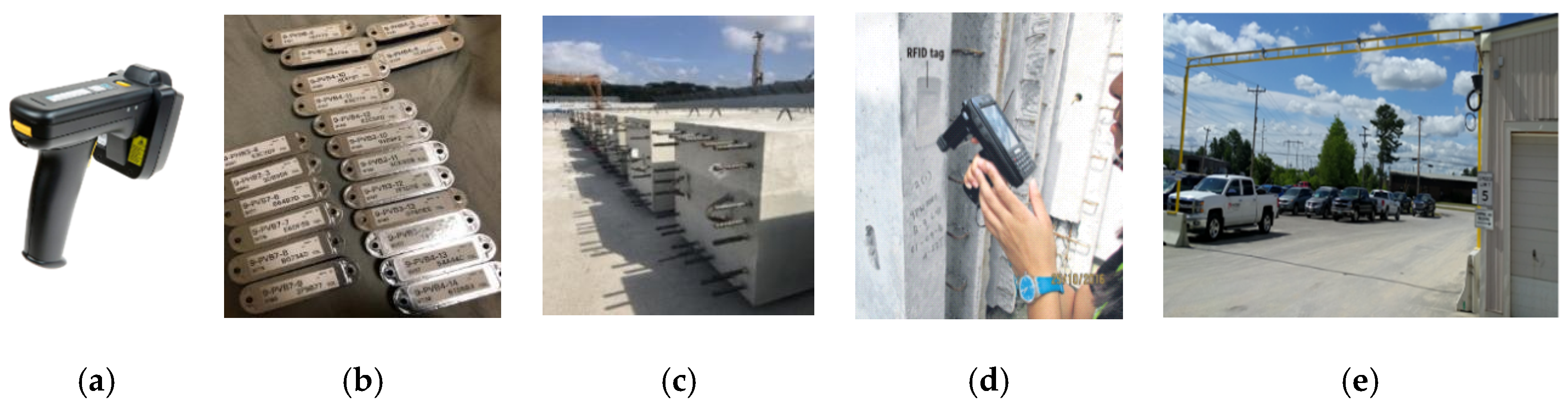
Integrated digital delivery (IDD) is initially proposed by Singapore’s Building and Construction Authority (BCA), which is the use of digital technologies such as BIM and virtual design and construction (VDC) to better integrate work processes and connect stakeholders working on the same project throughout the construction and building life cycle. RFID technology is used in the IDD program to facilitate a seamless logistics process from the precast plant to the construction site. Usually, passive RFID tags, which are encoded with unique ID numbers, are affixed on the precast products or embedded in them. The data in the RFID tags are then read by either a mobile RFID handheld or a fixed RFID portal. The GPS function in the reader would determine the location. If a Wi-Fi network is available, the data can be immediately sent to the back-end computer system. As such, movements of the precast products are tracked, as illustrated in Figure 2.
4.2.2. Automated Storage System
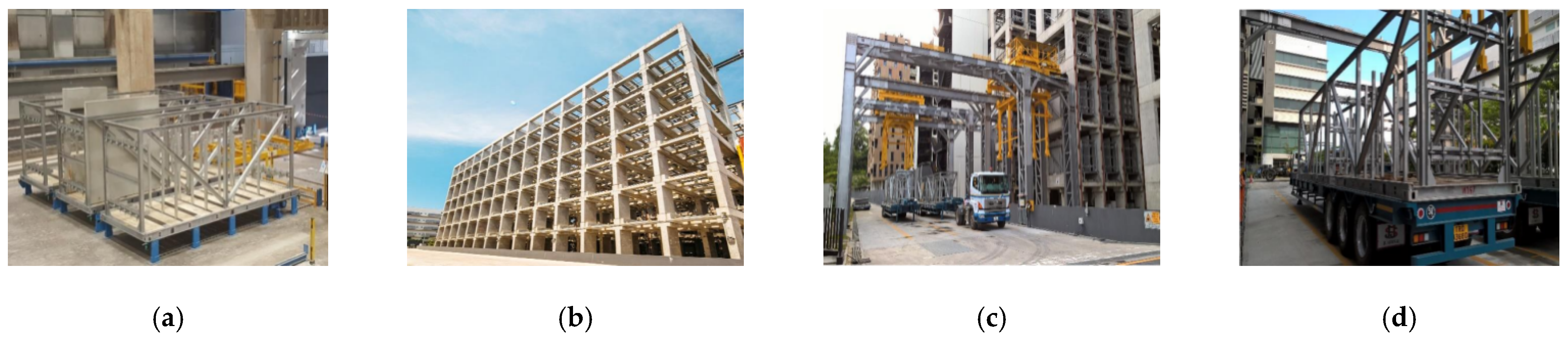
Nowadays, an advanced automated storage system is developed for precast products, as illustrated in Figure 3. Such a storage system can be constructed near the construction site as its material supply point. According to dispatched orders, the precast products are pre-sorted and stored in standard mobile racks, the sizes of which are compatible with the standard truck size. The loaded racks are then placed in the multi-level storage cells waiting for their delivery. When trucks come, overhead gantry cranes move the racks from the cells onto the trucks. IDs of the trucks, racks, and individual precast products are linked once they are physically together. Hence, by knowing the ID of a truck or a rack, IDs of its loaded products are known at once. Overhead RFID solutions, with fixed RFID readers installed in the overhead gantry, which can be installed at the exits and entrances of the plant, storage yard, and site, would automatically collect data remotely when trucks pass by, thus enabling a continuous stream of valuable real-time data.
4.2.3. BIM and RFID Integration Method
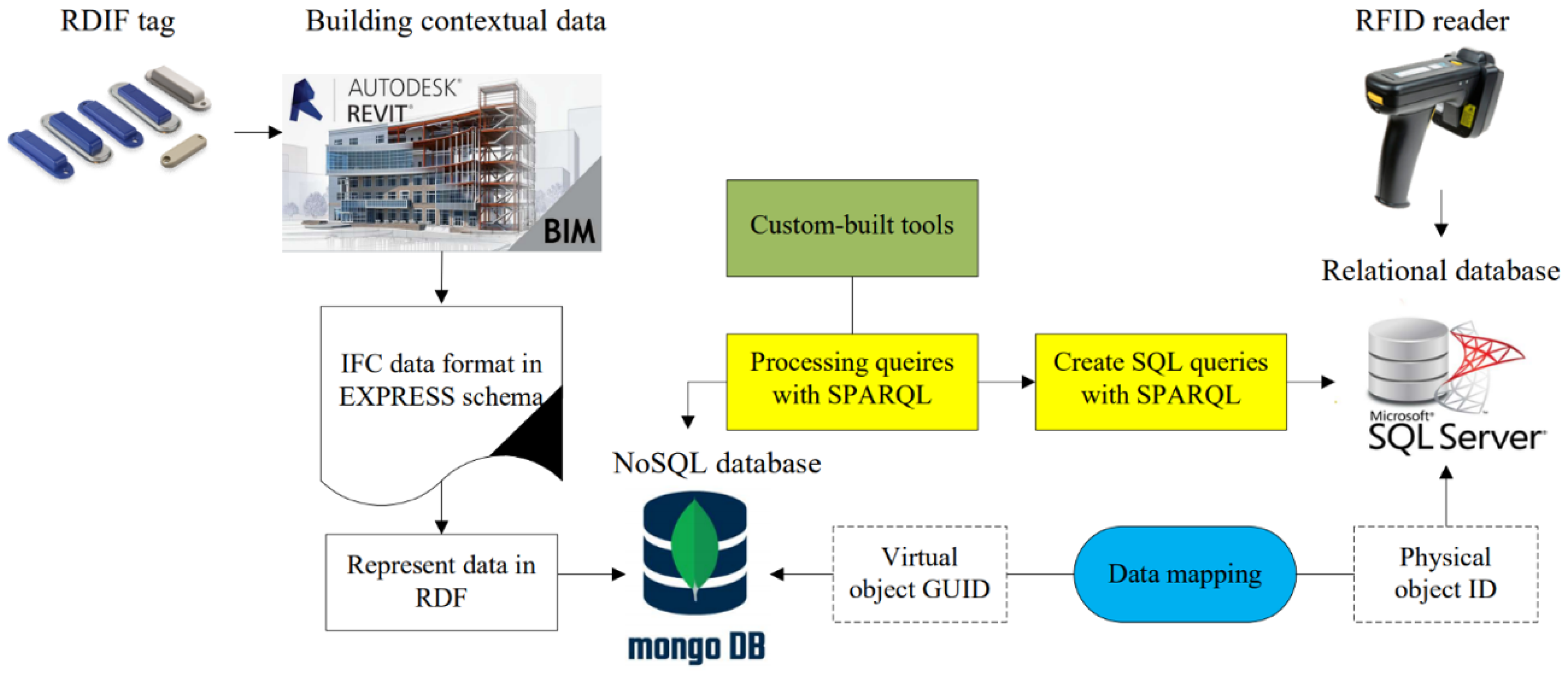
Figure 4 illustrates the method proposed to link RFID to BIM. The BIM model in software such as Revit is represented with the sensor information in the IFC data format in the EXPRESS schema. The IFC needs to be transformed into RDF by transforming an EXPRESS schema into RDF ontology using a semantic web approach. Following the development of the ifcOWL ontology, an IFC-to-RDF converter is developed. The underlying structure of any expression in RDF is a collection of triples, each consisting of a subject, a predictive, and an object. The RDF data are stored in a NoSQL database such as MongoDB database. On the other hand, the timeseries data collected by the RFID reader are stored in a relational database. The two databases are linked by defining the relationship between the virtual object globally unique identifier (GUID) and physical object ID. Last, contextual information represented in RDF is queried by SPARQL, while timeseries data stored in the relational database is queried using SQL. Since contextual information and timeseries data are mapped, SQL queries can be created based on SPARQL queries on RDF data.
4.3. BIM and LCA Integration
4.3.1. Common Data Structure and Naming Convention
A common data structure and naming convention construct the basis for automated data exchange between heterogeneous systems. They also facilitate a clearer and more consistent communication of building information across disciplines, which is helpful for the establishment of a public database.
There exist many classification systems for organizing information on buildings. Among them, Omniclass is a widely used classification system for life cycle applications. Omniclass consists of 15 hierarchical tables, each of which can be used independently to classify a particular type of information, representing a different facet of construction information. In BIM software Autodesk Revit, classifications can be assigned to elements with a single click through Classification Manager, which is a free tool. Once the classification system is adopted, people can communicate without the use of misleading common names.
4.3.2. Common Granularity in LCA and BIM
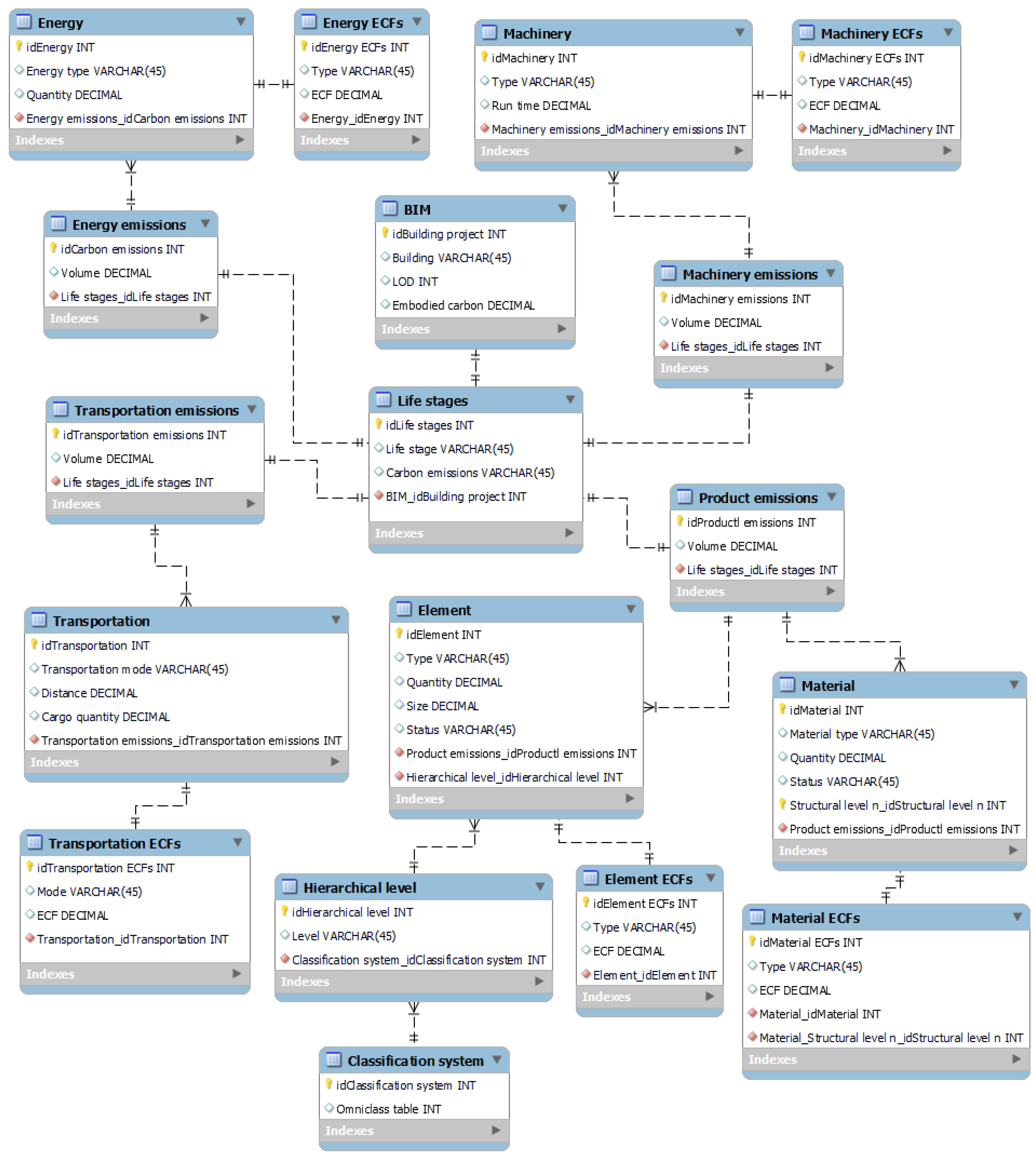
LoD defines the detailing levels in a BIM level. There are five different LoDs. From LoD 100 to LoD 500, building objects are described in more and more detail. Most LCA studies currently are based on LoD 300 to give roughly accurate results. LoD 300 level and above have defined the main components and materials in their actual size, shapes, and locations, so only for LoD 300 level and above can EPDs be used as a source, at the time that the exact brands of materials are known. However, it is preferred to work with LoD 200, i.e., with approximate volume, quantity, location, and orientation, for early-stage design. Usually, generic data are used when exact details are not yet available. The generic data are often created based on designs that serve similar functions of sample projects with similar building types. Therefore, a fast method is needed to calculate total embodied carbon impact for all possible design options to facilitate the process of making a decision. Common granularity in LCA and BIM is expected for the development of such a method. Figure 5 illustrates the general design idea for the LCA database.
4.3.3. Quantity Take-Off Process
Generally, a building part can be distinguished into two categories: discrete and non-discrete [62]. A non-discrete part is recognized by the following features: (1) with a viscous flow in the initial state (e.g., paint, spray, asphalt, or glue); (2) with small particles (e.g., gravel, cobble, or sand); (3) whose exact amount of use cannot be estimated before final installation (e.g., tapes, nails, or strip seals). Then, any part that cannot be recognized as a non-discrete part is categorized as a discrete part (e.g., columns, beams, doors, or windows).
The discrete and non-discrete categories enable appropriate building part quantification. The discrete building parts are counted in pieces, as they have clear boundaries, whereas the non-discrete building parts are measured by the amount of material. With the definition of a building part and the way to quantify building parts, it is possible to count the total number of building parts in a building project. Furthermore, using BIM, the quantity take-off process is totally automated.
Observing architecture designs that demonstrate a high repeating pattern, it is possible to use the number of building parts for certain sections to estimate the number of building parts for other similar sections. Hence, for unknown sections, the authors suggest selecting sample areas in similar type of buildings that serve similar functions to estimate their building parts.
4.3.4. Link of BIM and LCA
The BIM model therein provides a bill of quantities, which is a complete list of the materials including their properties (e.g., amount, area, and geometry) that are used in a building project, while the LCA database provides information on the embodied impact per unit of those materials. To establish an automated link between BIM and LCA database, a custom API should be developed. For the Revit BIM model, visual scripting software—Autodesk Dynamo [63]—can help. Dynamo can be run in either stand-alone mode or as a plug-in in Revit. It is a Python-based visual programming language that allows for retrieving and modifying information from a BIM model. One can connect elements to define the relationships and the sequences of actions that compose custom algorithms. Therefore, Dynamo can serve as a tool that links BIM and LCA.
5. Experimental Case
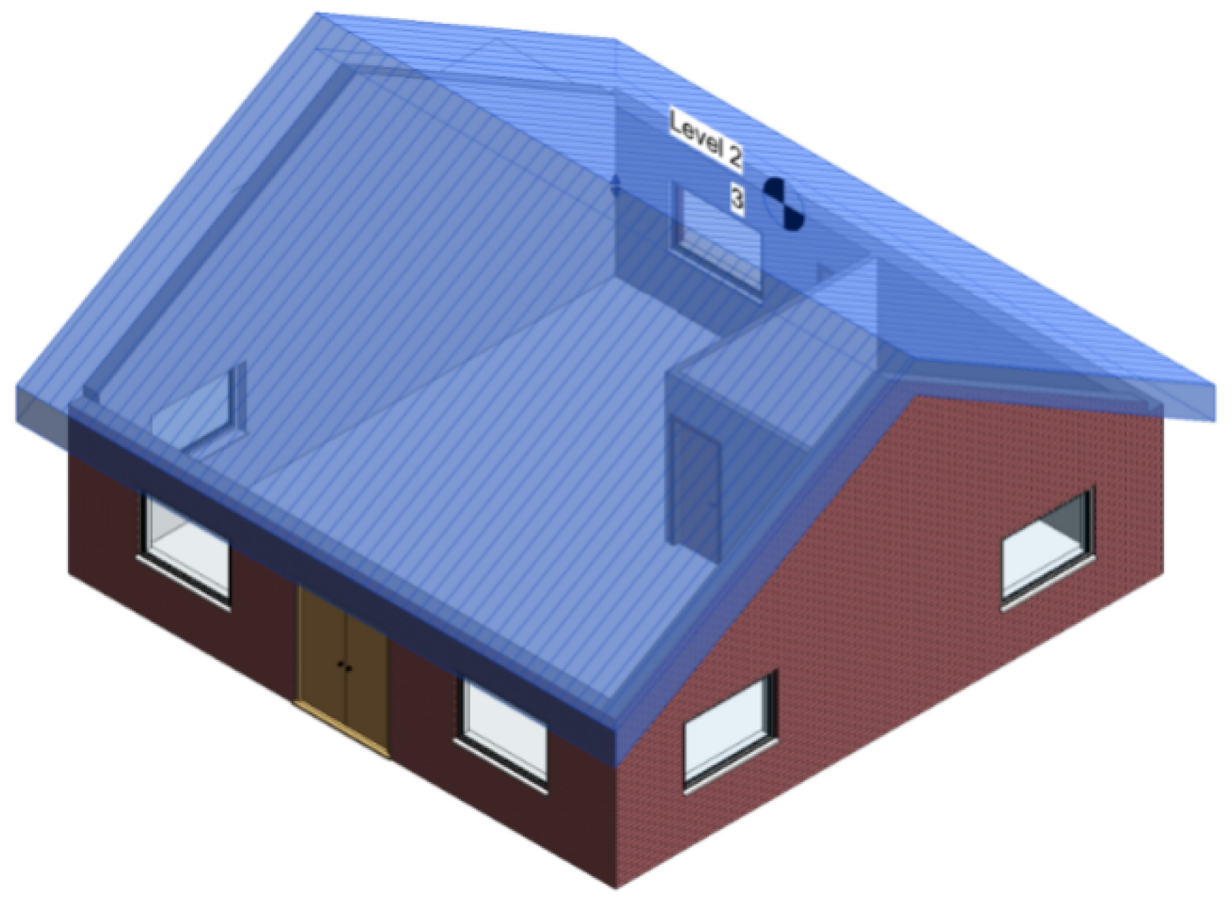
Because the integration method of RFID and BIM is a proven technology and the software Dynamo is well known for its capability of exporting and importing Revit data to and from an SQL database, the focus of this experimental case is placed on verifying the reasonableness of the database design using a small house example, as illustrated in Figure 6.
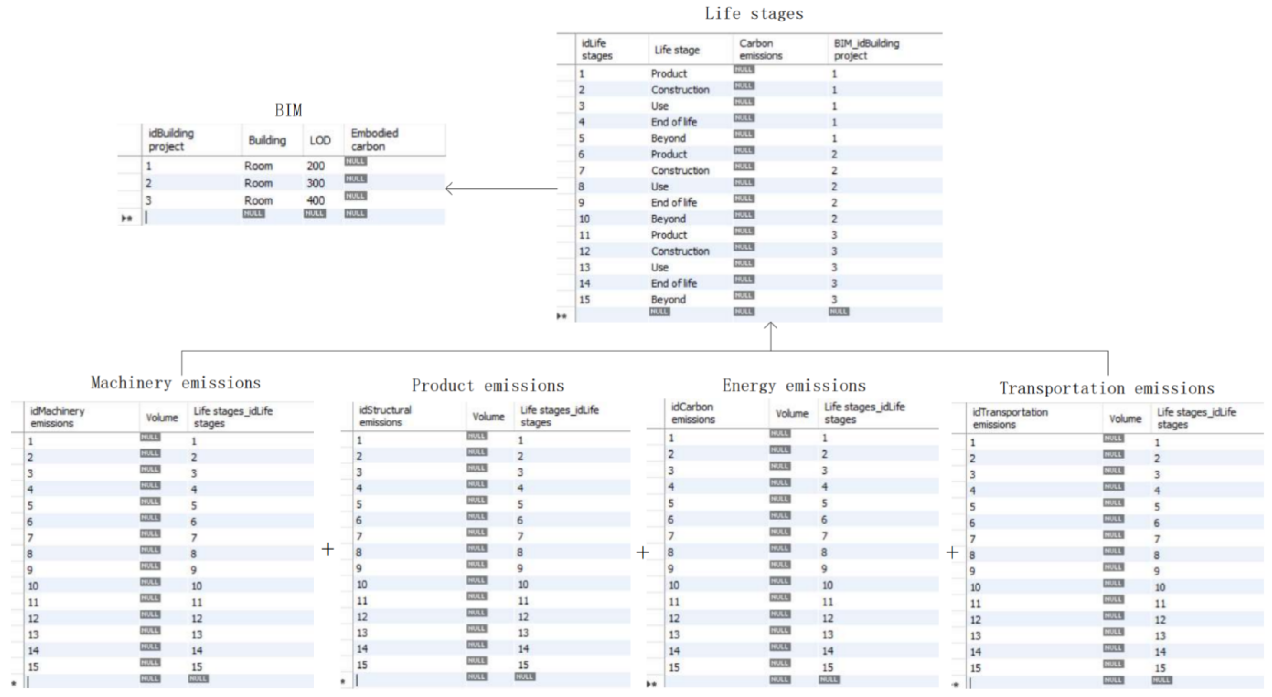
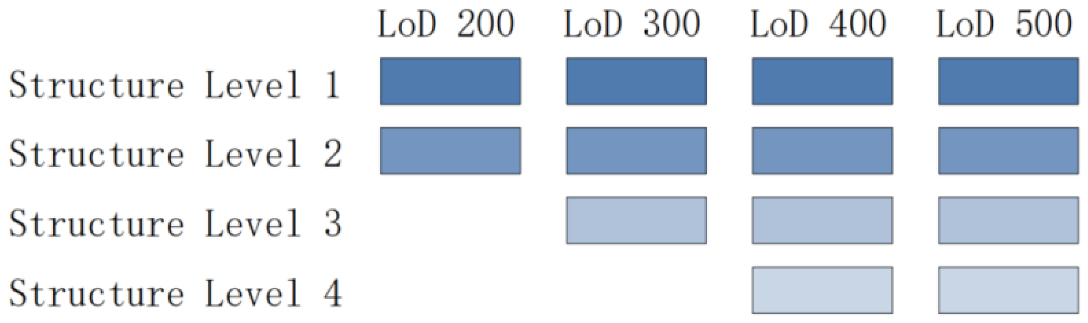
The total life cycle embodied carbon of the small house can be calculated based on different LoDs from the sum of five life stages—product stage, construction stage, use stage, end-of-life stage, and beyond stage—and four carbon emission sources—machinery emissions, product emissions, energy emissions, and transportation emissions—as illustrated in Figure 7. The house structural elements are hierarchically decomposed into multilevel systems according to Omniclass that are presented in Table 4. Data for higher levels may only be available when LoDs are higher. Hence, the data structure of different levels presents a downward-pointing triangular structure according to different LoDs, as shown in Figure 8. Given the ECFs, it is not difficult to calculate the carbon emission for each product/activity in each life stage from each emission source using the equations described in Section 4.1. Although the actual embodied carbon is calculated based on the LoD 500 model, it is also meaningful to convert the carbon emissions to lower LoD models for the design comparison purpose.
6. Discussion
The biggest challenge in developing such a system is the big data problem. LoD refers to the amount of information in the BIM model. For example, an LoD 300 for a seven-floor residential building that has a gross floor area of approximately 40,000 m2 can contain approximately 100,000 over virtual elements. Therefore, along with the progress of a building project, the amount of data is explosively increasing. A way to scale down the data size is to organize them in a hierarchical structure. As such, details in the low rank can be lump sum represented by the element in the high rank. However, the existing systems for organizing information on buildings usually do not go down to the detailed product level. It thus needs specific definitions that should be tailored to give clear guidance on the decomposition of different building parts.
Since the current IFC schema is not complete, a lot of new IFC elements may have to be developed. One example is the end-of-life stage, as abovementioned, in which no IFC classes for deconstruction exist. Another example would be product classification in which products come with details of sub-assemblies; generally, they are under-represented in the IFC schema. Furthermore, though BIM can include process-related data, the data are only used for scheduling purposes, a semantic approach for linking process data with carbon emissions is needed. Therefore, research is necessary to create new IFC elements for calculating the total embodied impact of the building.
7. Conclusions
The lack of a credible methodology for estimating embodied carbon limits the improvement of low-carbon design in the AEC industry. This paper thereby proposes a method that is based on digital twin technology and LCA as a better method. The proposed method is advantageous over the existing ones by providing (1) a cradle-to-cradle LCA and (2) a common granularity design of the LCA database and the BIM model for automatic data exchange. Because a process-based method is used for calculating the embodied impact of the building, and the processes are monitored via digital twin technology, while the data are collected in a standard and consistent way, the proposed method is considered more reliable.
This paper so far gives a conceptual framework that is supported by a comprehensive review conducted on a large amount of relevant literature. The proposed framework consists of three parts. The first part is about LCA calculation. The authors proposed a cradle-to-cradle LCA following the BS EN 15978 life cycle stages. Formulas for calculating the carbon emissions in each subsection of the life stages are given. Dynamic factors such as recurrent embodied impacts caused by maintenance and repair activities are also included. The second part is about BIM and IoT integration. An RFID-based digital twin platform is designed for real-time asset tracking in construction and the built environment. The main purpose to use the digital twin technology is to enable automated data capture to prevent data inconsistencies and errors in the process of entering data and updating information into the database system. With the digital twin, the system empowers the capability to react to future scenarios and changing conditions. For BIM and RFID integration, the authors recommended a hybrid approach that combines semantic web with a relational database, which is suitable for different kinds of projects including those large-scale and complex ones. The third part is about BIM and LCA integration. The key point in this part is to design one-to-one mapping between them to facilitate automated two-way data communication. The authors recommended using the same granularity in LCA and BIM databases, meanwhile using the same data structure and naming convention in them. The authors gave clear guidance for how to design the LCA database, how to make BIM elements following the same classification chosen for LCA, as well as how to link LCA and BIM. As assessing embodied carbon is most useful in early design stages when detailed information about buildings is not available yet, the proposed system BIM-based LCA system can provide a fast and automated method for evaluation of different design options to assist a low-carbon building design.
In the future, the authors will concretize the proposed idea to achieve a real system. Although the proposed framework represents a universal tool for estimating building embodied carbon, the LCA database and the classification system for organizing information on buildings exhibit regional characteristics. As a result, the authors have to adapt the system to China’s local conditions. A survey on the current status of different types of buildings in China is necessary.
Author Contributions
C.C.: writing—original draft preparation, conceptualization, funding acquisition. Z.Z.: investigation, writing—review and editing. J.X.: validation. R.T.: validation. All authors have read and agreed to the published version of the manuscript.
Funding
This research was supported by the Fundamental Research Funds for the Central Universities, funding numbers: 22120210372 and 22120210317 (Tongji University).
Institutional Review Board Statement
Not applicable.
Informed Consent Statement
Not applicable.
Data Availability Statement
Not applicable.
Acknowledgments
The authors would like to acknowledge Tongji University for the support from young scholar research funding.
Conflicts of Interest
The authors declare no conflict of interest. The funders had no role in the design of the study; in the collection, analyses, or interpretation of data; in the writing of the manuscript, or in the decision to publish the results.
Nomenclature
| Embodied carbon of a building | |
| Emissions in the product stage | |
| Emissions in the construction stage | |
| Emissions in the use stage | |
| Emissions in the end-of-life stage | |
| Emissions in the beyond stage | |
| Emissions associated with transport from factory to site | |
| Emissions concerned with waste in construction | |
| Site activity emissions in construction | |
| Emissions associated with use | |
| Emissions associated with maintenance | |
| Emissions associated with repair | |
| Emissions associated with replacement | |
| Emissions associated with refurbishment | |
| Emissions associated with deconstruction and demolition | |
| Emissions associated with transport away from site | |
| Emissions associated with waste processing | |
| Emissions associated with disposal | |
| Emissions associated with reuse and recycling | |
| Quantity of type building material (product) | |
| Quantity of type raw material | |
| Time of type machinery operation | |
| Quantity of type energy | |
| Quantity of type transport material (product) or construction equipment to site | |
| Quantity of type repair material (product) | |
| Quantity of type material (product) for replacement | |
| Quantity of type removal material (product) in refurbishment | |
| Quantity of type newly installed material (product) in refurbishment | |
| Quantity of type transport material (product) or construction equipment from site | |
| Quantity of type material (product) for waste processing | |
| Quantity of type material (product) for disposal | |
| Quantity of type material (product) for reuse and recycling | |
| Transport distance for type transport mode | |
| Waste factor for type material (product) | |
| Waste rate of type material (product) | |
| Reference study period | |
| Lifespan of type material (product) | |
| Embodied carbon factor |
References
- Tsinghua University. China Annual Development Research Report of Energy Efficiency Building; China Construction Industry Press: Beijing, China, 2020. [Google Scholar]
- Dixit, M.K.; Fernández-Solís, J.L.; Lavy, S.; Culp, C.H. Need for an embodied energy measurement protocol for buildings: A review paper. Renew. Sustain. Energy Rev. 2012, 16, 3730–3743. [Google Scholar] [CrossRef]
- UK Green Building Council. Tackling Embodied Carbon in Buildings. Available online: https://c40.my.salesforce.com/sfc/p/#36000001Enhz/a/1Q000000MfBS/FGxlhOt_O7z9uBON9a_ENb0HKOiiJovuFvQrf17O1ZA (accessed on 13 December 2021).
- Dixit, M.K. Life cycle embodied energy analysis of residential buildings: A review of literature to investigate embodied energy parameters. Renew. Sustain. Energy Rev. 2017, 79, 390–413. [Google Scholar] [CrossRef]
- Bahramian, M.; Yetilmezsoy, K. Life cycle assessment of the building industry: An overview of two decades of research (1995–2018). Energy Build. 2020, 219, 109917. [Google Scholar] [CrossRef]
- Gardezi, S.S.S.; Shafiq, N.; Zawawi, N.A.W.A.; Khamidi, M.F.; Farhan, S.A. A multivariable regression tool for embodied carbon footprint prediction in housing habitat. Habitat Int. 2016, 53, 292–300. [Google Scholar] [CrossRef]
- Su, X.; Zhang, X. A detailed analysis of the embodied energy and carbon emissions of steel-construction residential buildings in China. Energy Build. 2016, 119, 323–330. [Google Scholar] [CrossRef]
- Kumanayake, R.; Luo, H.; Paulusz, N. Assessment of material related embodied carbon of an office building in Sri Lanka. Energy Build. 2018, 166, 250–257. [Google Scholar] [CrossRef]
- Gan, V.J.L.; Cheng, J.C.P.; Lo, I.M.C.; Chan, C.M. Developing a CO2-e accounting method for quantification and analysis of embodied carbon in high-rise buildings. J. Clean. Prod. 2017, 141, 825–836. [Google Scholar] [CrossRef]
- Hoxha, V. Measuring embodied CO2 emission in construction materials in Kosovo apartments. Int. J. Build. Pathol. Adapt. 2019, 38, 405–421. [Google Scholar] [CrossRef]
- Architect. Policies for Embodied Carbon: An International Snapshot. 2020. Available online: https://www.architectmagazine.com/practice/policies-for-embodied-carbon-an-international-snapshot_o (accessed on 13 December 2021).
- The Institution of Structural Engineers. How to Calculate Embodied Carbon. 2020. Available online: https://www.istructe.org/IStructE/media/Public/Resources/istructe-how-to-calculate-embodied-carbon.pdf (accessed on 13 December 2021).
- Tao, F.; Zhang, H.; Liu, A.; Nee, A. Digital twin in industry: State-of-the-art. IEEE Trans. Ind. Inform. 2018, 15, 2405–2415. [Google Scholar] [CrossRef]
- Agnusdei, G.; Elia, V.; Gnoni, M. Is digital twin technology supporting safety management? A bibliometric and systematic review. Appl. Sci. 2021, 11, 2767. [Google Scholar] [CrossRef]
- Agnusdei, G.P.; Elia, V.; Gnoni, M.G. A classification proposal of digital twin applications in the safety domain. Comput. Ind. Eng. 2021, 154, 107137. [Google Scholar] [CrossRef]
- Agnusdei, G.P.; Aiello, G.; Certa, U.; Gnoni, M.G.; Longo, F.; Mirabelli, G. Health & safety 4.0: A digital twin reference model to support the smart operator at the workplace. In Proceedings of the 25th Summer School Francesco Turco Conference, Bergamo, Italy, 11 September 2020. [Google Scholar]
- Mannino, A.; Dejaco, M.; Cecconi, F.R. Building information modelling and internet of things integration for facility management—Literature review and future needs. Appl. Sci. 2021, 11, 3062. [Google Scholar] [CrossRef]
- Opoku, D.-G.J.; Perera, S.; Osei-Kyei, R.; Rashidi, M. Digital twin application in the construction industry: A literature review. J. Build. Eng. 2021, 40, 102726. [Google Scholar] [CrossRef]
- Zhang, X.; Wang, F. Analysis of embodied carbon in the building life cycle considering the temporal perspectives of emissions: A case study in China. Energy Build. 2017, 155, 404–413. [Google Scholar] [CrossRef]
- Zhu, W.; Feng, W.; Li, X.; Zhang, Z. Analysis of the embodied carbon dioxide in the building sector: A case of China. J. Clean. Prod. 2020, 269, 122438. [Google Scholar] [CrossRef]
- Dixit, M. Embodied energy analysis of building materials: An improved IO-based hybrid method using sectoral disaggregation. Energy 2017, 124, 46–58. [Google Scholar] [CrossRef]
- Zhang, X.; Zhang, X. A subproject-based quota approach for life cycle carbon assessment at the building design and construction stage in China. Build. Environ. 2020, 185, 107258. [Google Scholar] [CrossRef]
- Kang, G.; Cho, H.; Lee, D. Dynamic lifecycle assessment in building construction projects: Focusing on embodied emissions. Sustainability 2019, 11, 3724. [Google Scholar] [CrossRef] [Green Version]
- Resch, E.; Andresen, I.; Cherubini, F.; Brattebø, H. Estimating dynamic climate change effects of material use in buildings—Timing, uncertainty, and emission sources. Build. Environ. 2020, 187, 107399. [Google Scholar] [CrossRef]
- Yeo, Z.; Ng, R.; Song, B. Technique for quantification of embodied carbon footprint of construction projects using probabilistic emission factor estimators. J. Clean. Prod. 2016, 119, 135–151. [Google Scholar] [CrossRef]
- Serrano, A.R.; Álvarez, S.P. Life cycle assessment in building: A case study on the energy and emissions impact related to the choice of housing typologies and construction process in Spain. Sustainability 2016, 8, 287. [Google Scholar] [CrossRef] [Green Version]
- Lotteau, M.; Loubet, P.; Sonnemann, G. An analysis to understand how the shape of a concrete residential building influences its embodied energy and embodied carbon. Energy Build. 2017, 154, 1–11. [Google Scholar] [CrossRef]
- Finnegan, S.; Jones, C.; Sharples, S. The embodied CO2e of sustainable energy technologies used in buildings: A review article. Energy Build. 2018, 181, 50–61. [Google Scholar] [CrossRef]
- Moncaster, A.; Pomponi, F.; Symons, K.; Guthrie, P. Why method matters: Temporal, spatial and physical variations in LCA and their impact on choice of structural system. Energy Build. 2018, 173, 389–398. [Google Scholar] [CrossRef]
- Pomponi, F.; Moncaster, A. Scrutinising embodied carbon in buildings: The next performance gap made manifest. Renew. Sustain. Energy Rev. 2018, 81, 2431–2442. [Google Scholar] [CrossRef] [Green Version]
- De Wolf, C.; Hoxha, E.; Hollberg, A.; Fivet, C.; Ochsendorf, J. Database of embodied quantity outputs: Lowering material impacts through engineering. J. Arch. Eng. 2020, 26, 04020016. [Google Scholar] [CrossRef]
- Shadram, F.; Johansson, T.D.; Lu, W.; Schade, J.; Olofsson, T. An integrated BIM-based framework for minimizing embodied energy during building design. Energy Build. 2018, 128, 592–604. [Google Scholar] [CrossRef]
- Yang, X.; Hu, M.; Wu, J.; Zhao, B. Building-information-modeling enabled life cycle assessment, a case study on carbon footprint accounting for a residential building in China. J. Clean. Prod. 2018, 183, 729–743. [Google Scholar] [CrossRef]
- Lu, Y.; Le, V.H.; Song, X. Beyond boundaries: A global use of life cycle inventories for construction materials. J. Clean. Prod. 2017, 156, 876–887. [Google Scholar] [CrossRef]
- Eleftheriadis, S.; Mumovic, D.; Greening, P. Life cycle energy efficiency in building structures: A review of current developments and future outlooks based on BIM capabilities. Renew. Sustain. Energy Rev. 2017, 67, 811–825. [Google Scholar] [CrossRef] [Green Version]
- Peng, C. Calculation of a building’s life cycle carbon emissions based on Ecotect and building information modeling. J. Clean. Prod. 2016, 112, 453–465. [Google Scholar] [CrossRef]
- Wang, J.; Wu, H.; Duan, H.; Zillante, G.; Zuo, J.; Yuan, H. Combining life cycle assessment and Building Information Modelling to account for carbon emission of building demolition waste: A case study. J. Clean. Prod. 2018, 172, 3154–3166. [Google Scholar] [CrossRef]
- Nizam, R.S.; Zhang, C.; Tian, L. A BIM based tool for assessing embodied energy for buildings. Energy Build. 2018, 170, 1–14. [Google Scholar] [CrossRef]
- Hao, J.L.; Cheng, B.; Lu, W.; Xu, J.; Wang, J.; Bu, W.; Guo, Z. Carbon emission reduction in prefabrication construction during materialization stage: A BIM-based life-cycle assessment approach. Sci. Total. Environ. 2020, 723, 137870. [Google Scholar] [CrossRef] [PubMed]
- Sun, H.; Park, Y. CO2 emission calculation method during construction process for developing BIM-based performance evaluation system. Appl. Sci. 2020, 10, 5587. [Google Scholar] [CrossRef]
- Panteli, C.; Kylili, A.; Fokaides, P.A. Building information modelling applications in smart buildings: From design to commissioning and beyond A critical review. J. Clean. Prod. 2020, 265, 121766. [Google Scholar] [CrossRef]
- Obrecht, T.P.; Röck, M.; Hoxha, E.; Passer, A. BIM and LCA integration: A systematic literature review. Sustainability 2020, 12, 5534. [Google Scholar] [CrossRef]
- Safari, K.; AzariJafari, H. Challenges and opportunities for integrating BIM and LCA: Methodological choices and framework development. Sustain. Cities Soc. 2021, 67, 102728. [Google Scholar] [CrossRef]
- Seyis, S. Mixed method review for integrating building information modeling and life-cycle assessments. Build. Environ. 2020, 173, 106703. [Google Scholar] [CrossRef]
- Santos, R.; Costa, A.A.; Silvestre, J.D.; Pyl, L. Integration of LCA and LCC analysis within a BIM-based environment. Autom. Constr. 2019, 103, 127–149. [Google Scholar] [CrossRef]
- Roberts, M.; Allen, S.; Coley, D. Life cycle assessment in the building design process—A systematic literature review. Build. Environ. 2020, 185, 107274. [Google Scholar] [CrossRef]
- Röck, M.; Hollberg, A.; Habert, G.; Passer, A. LCA and BIM: Visualization of environmental potentials in building construction at early design stages. Build. Environ. 2018, 140, 153–161. [Google Scholar] [CrossRef]
- Santos, R.; Costa, A.A.; Silvestre, J.D.; Pyl, L. Informetric analysis and review of literature on the role of BIM in sustainable construction. Autom. Constr. 2019, 103, 221–234. [Google Scholar] [CrossRef]
- Soust-Verdaguer, B.; Llatas, C.; García-Martínez, A. Critical review of bim-based LCA method to buildings. Energy Build. 2017, 136, 110–120. [Google Scholar] [CrossRef]
- Cavalliere, C.; Habert, G.; Dell’Osso, G.R.; Hollberg, A. Continuous BIM-based assessment of embodied environmental impacts throughout the design process. J. Clean. Prod. 2019, 211, 941–952. [Google Scholar] [CrossRef]
- Deng, M.; Menassa, C.C.; Kamat, V.R. From BIM to digital twins: A systematic review of the evolution of intelligent building representations in the AEC-FM industry. J. Inf. Technol. Constr. 2021, 26, 58–83. [Google Scholar] [CrossRef]
- Boje, C.; Guerriero, A.; Kubicki, S.; Rezgui, Y. Towards a semantic construction digital twin: Directions for future research. Autom. Constr. 2020, 114, 103179. [Google Scholar] [CrossRef]
- Alshammari, K.; Beach, T.; Rezgui, Y. Cybersecurity for digital twins in the built environment: Current research and future directions. J. Inf. Technol. Constr. 2021, 26, 159–173. [Google Scholar] [CrossRef]
- buildingSMART. Available online: https://standards.buildingsmart.org/IFC/RELEASE/IFC4/FINAL/HTML/schema/ifcbuildingcontrolsdomain/lexical/ifcsensor.htm (accessed on 13 December 2021).
- Quinn, C.; Shabestari, A.Z.; Misic, T.; Gilani, S.; Litoiu, M.; McArthur, J. Building automation system—BIM integration using a linked data structure. Autom. Constr. 2020, 118, 103257. [Google Scholar] [CrossRef]
- Moretti, N.; Xie, X.; Merino, J.; Brazauskas, J.; Parlikad, A.K. An openBIM approach to IoT integration with incomplete as-built data. Appl. Sci. 2020, 10, 8287. [Google Scholar] [CrossRef]
- Tang, S.; Shelden, D.R.; Eastman, C.M.; Pishdad-Bozorgi, P.; Gao, X. A review of building information modeling (BIM) and the internet of things (IoT) devices integration: Present status and future trends. Autom. Constr. 2019, 101, 127–139. [Google Scholar] [CrossRef]
- Akbarieh, A.; Jayasinghe, L.B.; Waldmann, D.; Teferle, F.N. BIM-based end-of-lifecycle decision making and digital deconstruction: Literature review. Sustainability 2020, 12, 2670. [Google Scholar] [CrossRef] [Green Version]
- Ozturk, G.B. Digital twin research in the AECO-FM industry. J. Build. Eng. 2021, 40, 102730. [Google Scholar] [CrossRef]
- Sepasgozar, S. Differentiating digital twin from digital shadow: Elucidating a paradigm shift to expedite a smart, sustainable built environment. Buildings 2021, 11, 151. [Google Scholar] [CrossRef]
- Frankó, A.; Vida, G.; Varga, P. Reliable identification schemes for asset and production tracking in industry 4.0. Sensors 2020, 20, 3709. [Google Scholar] [CrossRef]
- Zhao, N.; Kam, C.; Lo, J.T.Y.; Kim, J.I.; Fischer, M. Construction parts in building projects: Definition and case study. J. Manag. Eng. 2018, 34, 04018014. [Google Scholar] [CrossRef]
- Autodesk. Dynamo. Available online: https://dynamobim.org (accessed on 13 December 2021).
Figure 1.
The proposed framework for estimating building embodied carbon based on digital twin and life cycle assessment.
Figure 1.
The proposed framework for estimating building embodied carbon based on digital twin and life cycle assessment.

Figure 2.
RFID tracking for integrated digital delivery. (a) RFID Reader; (b) RFID Tags; (c) Affixed to components; (d) Read by RFID handheld; (e) Read by fixed RFID portal.
Figure 2.
RFID tracking for integrated digital delivery. (a) RFID Reader; (b) RFID Tags; (c) Affixed to components; (d) Read by RFID handheld; (e) Read by fixed RFID portal.

Figure 3.
Automated storage system for precast products. (a) Standard metal rack; (b) Multi-level storage cells; (c) Overhead gantry cranes; (d) Truck delivery.
Figure 3.
Automated storage system for precast products. (a) Standard metal rack; (b) Multi-level storage cells; (c) Overhead gantry cranes; (d) Truck delivery.

Figure 4.
RDF BIM integrated with relational database.

Figure 5.
Sample LCA database design.

Figure 6.
A house example.

Figure 7.
Decomposition of embodied carbon according to different LoDs.

Figure 8.
Data structure of the house structural elements according to different LoDs.


Table 1.
Search methodology.
| Search String | KEY (“life cycle” AND “embodied carbon, building”) OR (“life cycle assessment” AND “BIM”) OR (“digital twin” AND “construction”) OR (“digital twin” AND “IoT”) OR (“BIM” AND “IoT”) |
| Subject areas | “Engineering” |
| Publication type | Journal articles in English |
| Database | Scopus |
| Period | 2016–2021 |
Table 2.
Review sources of journals and the identified articles.
| Journals | Publisher | Number of Articles | ||
|---|---|---|---|---|
| Embodied Carbon | BIM–LCA | Digital Twin | ||
| Energy and Buildings | Elsevier | 8 | 2 | |
| Journal of Cleaner Production | Elsevier | 3 | 6 | |
| Building and Environment | Elsevier | 2 | 3 | |
| Automation in Construction | Elsevier | 2 | 3 | |
| Renewable and Sustainable Energy Reviews | Elsevier | 2 | 1 | |
| Journal of Building Engineering | Elsevier | 2 | ||
| Habitat International | Elsevier | 1 | ||
| Energy | Elsevier | 1 | ||
| Sustainable Cities and Society | Elsevier | 1 | ||
| Science of the Total Environment | Elsevier | 1 | ||
| Journal of Architectural Engineering | ASCE | 1 | ||
| International Journal of Building Pathology and Adaption | Emerald | 1 | ||
| Sustainability (Switzerland) | MDPI | 3 | 3 | 1 |
| Applied Sciences (Switzerland) | MDPI | 1 | 1 | |
| Sensors (Switzerland) | MDPI | 2 | ||
| Buildings | MDPI | 1 | ||
| Journal of Information Technology in Construction | CIB | 2 | ||
| Total | 22 | 20 | 12 | |
Table 3.
Site waste scenarios.
| Disposal to Landfill/Incineration | Reuse or Recycling On-Site | Reuse or Recycling Off-Site | Excavation |
|---|---|---|---|
| [A1 − A3] + [A4] + [C2] + [C4] | [A1 − A3] + [A4] + [C3] | [A1 − A3] + [A4] + [C2] +[C3] | [C2] + [C4] |
Table 4.
Hierarchical decomposition of the house structure according to Omniclass.
| Level 1 | Level 2 | Level 3 | Level 4 |
|---|---|---|---|
| Shell | Superstructure | Floor construction | Floor structural frame |
| Floor decks, slabs, and toppings | |||
| Floor construction supplementary components | |||
| Roof construction | Roof structural frame | ||
| Roof decks, slabs, and sheathing | |||
| Roof construction supplementary components | |||
| Exterior vertical enclosures | Exterior walls | Exterior wall veneer | |
| Exterior wall construction | |||
| Exterior wall interior skin | |||
| Fabricated exterior wall assemblies | |||
| Exterior wall supplementary components | |||
| Exterior wall opening supplementary components | |||
| Exterior windows | Exterior fixed windows | ||
| Exterior doors and grilles | Exterior entrance doors | ||
| Exterior door supplementary components | |||
| Exterior horizontal enclosures | Roofing | Low-slope roofing | |
| Roofing supplementary components | |||
| Interiors | Interior construction | Interior partitions | Interior fixed partitions |
| Interior partition supplementary components | |||
| Interior doors | Interior swinging doors | ||
| Interior door supplementary components | |||
| Interior finishes | Wall finishes | Wall painting and coating | |
| Wall finish supplementary components | |||
| Flooring | Flooring treatment | ||
| Tile flooring | |||
| Flooring supplementary components |
Publisher’s Note: MDPI stays neutral with regard to jurisdictional claims in published maps and institutional affiliations. |
© 2021 by the authors. Licensee MDPI, Basel, Switzerland. This article is an open access article distributed under the terms and conditions of the Creative Commons Attribution (CC BY) license (https://creativecommons.org/licenses/by/4.0/).
Share and Cite
MDPI and ACS Style
Chen, C.; Zhao, Z.; Xiao, J.; Tiong, R. A Conceptual Framework for Estimating Building Embodied Carbon Based on Digital Twin Technology and Life Cycle Assessment. Sustainability 2021, 13, 13875. https://doi.org/10.3390/su132413875
AMA Style
Chen C, Zhao Z, Xiao J, Tiong R. A Conceptual Framework for Estimating Building Embodied Carbon Based on Digital Twin Technology and Life Cycle Assessment. Sustainability. 2021; 13(24):13875. https://doi.org/10.3390/su132413875
Chicago/Turabian StyleChen, Chen, Zengfeng Zhao, Jianzhuang Xiao, and Robert Tiong. 2021. "A Conceptual Framework for Estimating Building Embodied Carbon Based on Digital Twin Technology and Life Cycle Assessment" Sustainability 13, no. 24: 13875. https://doi.org/10.3390/su132413875
Note that from the first issue of 2016, this journal uses article numbers instead of page numbers. See further details here.