1. Introduction
Given its important role for economies and societies, the preventive conservation and maintenance of the built cultural heritage (BCH) continue to stand as major priorities of the overall political strategy at the European level. In this context, the earthquake protection of historic masonry structures (HMSs) assumes particular relevance because of the non-negligible seismic vulnerability of this type of ancient buildings whose tangible and intangible value is further enhanced by the artworks therein located, such as sculptures, paintings and frescos, among others. This means that when a disaster involves HMSs, it is likely that artworks are damaged, producing not only a physical loss of artistic and historical materials, but also an immaterial loss of memory and cultural identity for the people to whom that legacy “belongs”.
In the last decade, impressive advancements have been made in the documentation and preservation of the BCH structural integrity. The possibilities offered by today’s tools and workflows for digital representation, information and management, open new yet challenging perspectives in terms of geometry acquisition [
1,
2,
3], and data dissemination. Given the framework above, the concept of Digital Twin (DT), originally defined as “A model of the physical object or system, which connects digital and physical assets, transmits data in at least one direction, and monitors the physical system in real-time” [
4], has gradually attracted the attention of the building sector. As a result, the DT concept is becoming popular as a comprehensive approach to manage, plan, predict, and demonstrate building infrastructure or city assets [
5,
6,
7]. Concerning the historic masonry structures, an early attempt involving the development of a comprehensive methodology to structure and integrate the significance of tangible and intangible elements into HBIM models was proposed by Angjeliu et al. (2020) [
8]. However, applications to the HMS are very limited, and many technical challenges still need to be addressed to achieve the full utilisation of this powerful tool. Major pending issues include the rapid yet accurate collection and modelling of spatial and nonspatial data, the online monitoring of the structural health, the realistic numerical simulation of the system behaviour against plausible future scenarios, and the real-time assessment of the structural condition for fast decision making during emergency operations.
Thanks to the evolution of geomatics methodologies, several solutions are available nowadays for the generation of refined models of real-world structures, exploiting either automatic or semi-automatic meshing of the point clouds [
9] and resorting to manual or parametric modelling approaches [
10]. This phase of transition from half-raw survey data (point clouds) to realistic parametric models, typical of BIM projects, is known as Scan-to-FEM. Such a step may be rather demanding in case of BCH because of the irregular and complex shapes often characterising historic buildings. This step is typically carried out using remote sensing techniques, i.e., laser scanning and digital photogrammetry [
11,
12,
13].
From the structural perspective, point clouds cannot be used for numerical analyses because they are formed by many discrete points defined by three-dimensional coordinates. In order to effectively use the geometric data derived by 3D laser scanning for structural purposes, it is necessary to perform operations that transform a point cloud into a continuum model. To handle these processes, several approaches have been recently proposed in the literature for the automatic mesh generation of HMS models from 3D point clouds. Barazzetti et al. [
9] proposed a two-step methodology to convert the point cloud to a BIM model and then import the model into an FEM software. They demonstrated how the BIM approach could be applied to achieve structural analysis aims without creating ad hoc models only for the purpose of structural simulation. Castellazzi et al. [
14] designed a new semi-automatic procedure to transform three-dimensional point clouds of complex objects to three-dimensional finite element models. The procedure aimed at solving the problems connected to the generation of FE models of complicated structures by constructing a fine discretised geometry with a reduced amount of time and ready to be employed for structural analyses. Similarly, Fortunato et al. [
15] and Pepe et al. [
16] developed Scan-to-FEM procedures suitable for historic masonry structures characterised by several geometrical irregularities. Although worthy of notice, none of the referred procedures employs algorithms able to provide a general solution to the problem; indeed, the development and the optimisation of Scan-to-FEM tools appropriate for BCH is still an ongoing process. Another key issue not to overlook concerns the crucial role that the generation of a three-dimensional model plays to improve the monument knowledge level, hence it cannot be considered totally user-independent.
The application of the DT concept to the protection and conservation of the BCH implies the possibility to accurately simulate the structural response over time in order to understand its behaviour and prevent future problems. To achieve this, the BCH must be instrumented by means of an appropriate sensor network for data-driven condition monitoring, ideally coupled with a detailed numerical model of the structure validated on the basis of acquired field data. In particular, the data collected through permanent vibration monitoring systems may be exploited to automatically calibrate and update the structural model characteristics through the use of internet of things (IoT) technology [
17,
18]. During this process, it is possible to quantify the degree of representativeness and accuracy of the digital model and, further on, to identify the necessary steps to be undertaken if the model is to be improved. In this framework, numerical simulations give a significant contribution to the prediction of possible future damage scenarios and, accordingly, to the definition of appropriate warning levels. In particular, in what concerns BCH, structural analyses against critical scenarios can be profitably used to uncover the weakest parts of the system and to identify in advance the most probable damage locations following adequate seismic scenarios of different magnitude. In the last decade, numerical models, either based on the Discrete Element Method (DEM) or FEM approaches, have been extensively used for dynamic analysis of the HMS [
19]. DEM was found particularly suitable to model large displacement dynamics, typically associated with low-mortar strength masonry, which is a common characteristic of BCH [
20,
21]. However, FEM approach is still the most used strategy because of its suitability for simulating the structures’ dynamic behaviour [
3,
22]. In particular, FEM models are useful to conduct classical modal analysis [
23,
24] that could be, in turn, compared and fitted to the actual one issued from SHM tools [
2,
25,
26]. In this regard, several applications can be found in the literature, also referring to historical constructions [
2,
27].
In light of the above, it is worth remarking how generating digital replicas of historic masonry structures is a challenging and often burdensome task, which goes far beyond a slavish geometric representation. It is necessary to reconstruct the life of the monument, thus including any intervention or damage-induced change that occurred across centuries, also resulting from anthropogenic actions. Afterwards, historic analysis and experimental evidence must be combined to verify the initial hypotheses made on the model, and monitoring tools must be considered to track and keep up to date the response of the structure in order to promptly detect anomalous behaviours. Indeed, the development of a digital replica, able to monitor in real-time the evolution of the behaviour of existing structures, is in accordance with the state-of-art recommendations for the preservation of the BCH, inspired by the Venice Charter principles (1964) [
28].
The present paper aims to define a parametric Scan-to-FEM framework for the DT generation of HMSs, which is straightforward and computationally efficient in case of massive buildings characterised by the repetition of architectural and structural modules and/or components. The proposed procedure exploits the flow-based programming paradigm, in which the user can interact with the code by modifying and/or implementing new capabilities. It also includes the definition of a Python script for the real-time interoperability between Rhino3D + Grasshopper [
29,
30] and Abaqus CAE [
31]. The approach has been applied and validated through an emblematic case study: the Church of St. Torcato in Guimarães (Portugal).
This study aims at exploring the potential of Generative Programming, whose efficiency has been already demonstrated in the scientific literature with other aims [
32,
33,
34,
35], for the Scan-to-FEM purpose. As previously mentioned, the code relies on flow-based programming, having the point cloud of the structure as an input, whereas the outcome consists of proper script files for the real-time importing into an FEM software. To accomplish the latter, the framework described next has been followed:
Acquisition of qualitative and quantitative data for the case study.
Geometrical and formal analysis of the structure. In this context, the research question is this: Can the case study be discretised parametrically by identifying (i) entities, (ii) sub-entities, (iii) modules and repetitions, iv) symmetries?
Implementation of instance-based parametric components for each structural module using Python programming languages. The so-created library of elements can be visualised in Rhino3D + Grasshopper [
29,
30] software.
Integration of the geometrical asset along with the mechanical characteristics of the structural elements and parametrisation of the damage.
Development of a proper script for the real-time link between the parametric environment and the finite element software.
Calibration of the numerical model.
The novelties of the study are threefold and are outlined next:
Pioneering application of Generative Algorithm to historic masonry structures.
Definition of a “real-time” bridge to couple geometrical asset and finite element model.
Calibration of the digital copy of the analysed church through long-term monitoring data and simulation of its future response against likely adverse scenarios.
The paper is organised as follows.
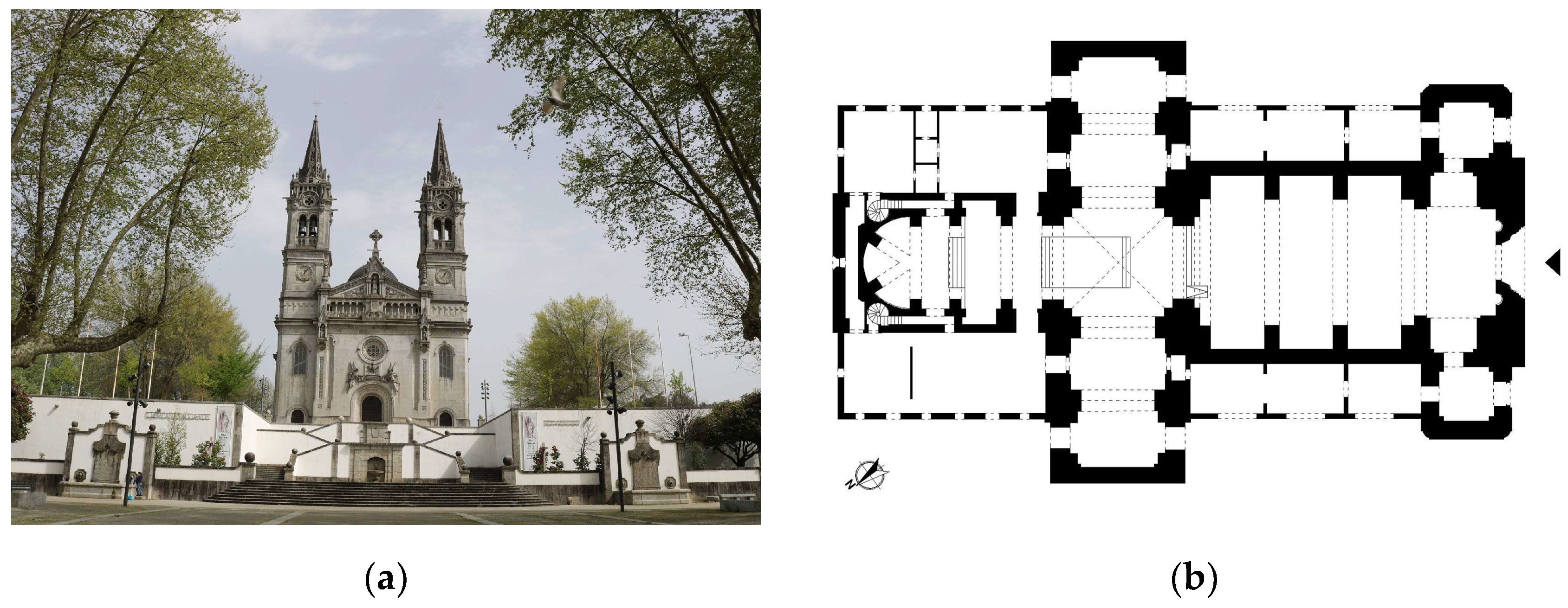
Section 2 presents the case of study from the historical, material and geometrical point of view;
Section 3 describes the Generative Scan-to-FEM Algorithm;
Section 4 focuses on the FE model calibration performed on both strengthened and unstrengthened configuration of the church.
Section 5 demonstrates how the digital twin can be exploited to predict the structural behaviour in response to simulated critical scenarios. Finally, some remarkable conclusions are reported in
Section 6.
3. Generative Scan-to-FEM Algorithm
The software industry is currently focusing on the definition of parametric-based modelling approaches, which allow performing in no time the transition from half-raw survey data (point clouds) to 3D geometrical entities, i.e., CAD or BIM elements. Such approaches may be widely applicable to heritage buildings because they are frequently characterised by architectural layouts consisting of regular modules and repetition of architectural orders [
38,
39]. In this context, Generative Programming (GP) appears as a reliable and efficient solution, being a programming paradigm based on the code-reuse concepts, which imply the use of the coding knowledge following the reusability principles [
40].
Because of its potential, GP has been widely employed for the design of new optimised buildings having exciting shapes, whereas only a few applications to historic masonry buildings are present hitherto in the literature [
41]. The main limitation is that a parametric approach may not be suitable for nonregular structures. In such cases, the modelling must be performed manually or by blending other kinds of 3D modelling generation, e.g., polygonal modelling [
15].
In the following subsections, a GP paradigm is adopted for the Scan-to-FEM migration of St. Torcato Church.
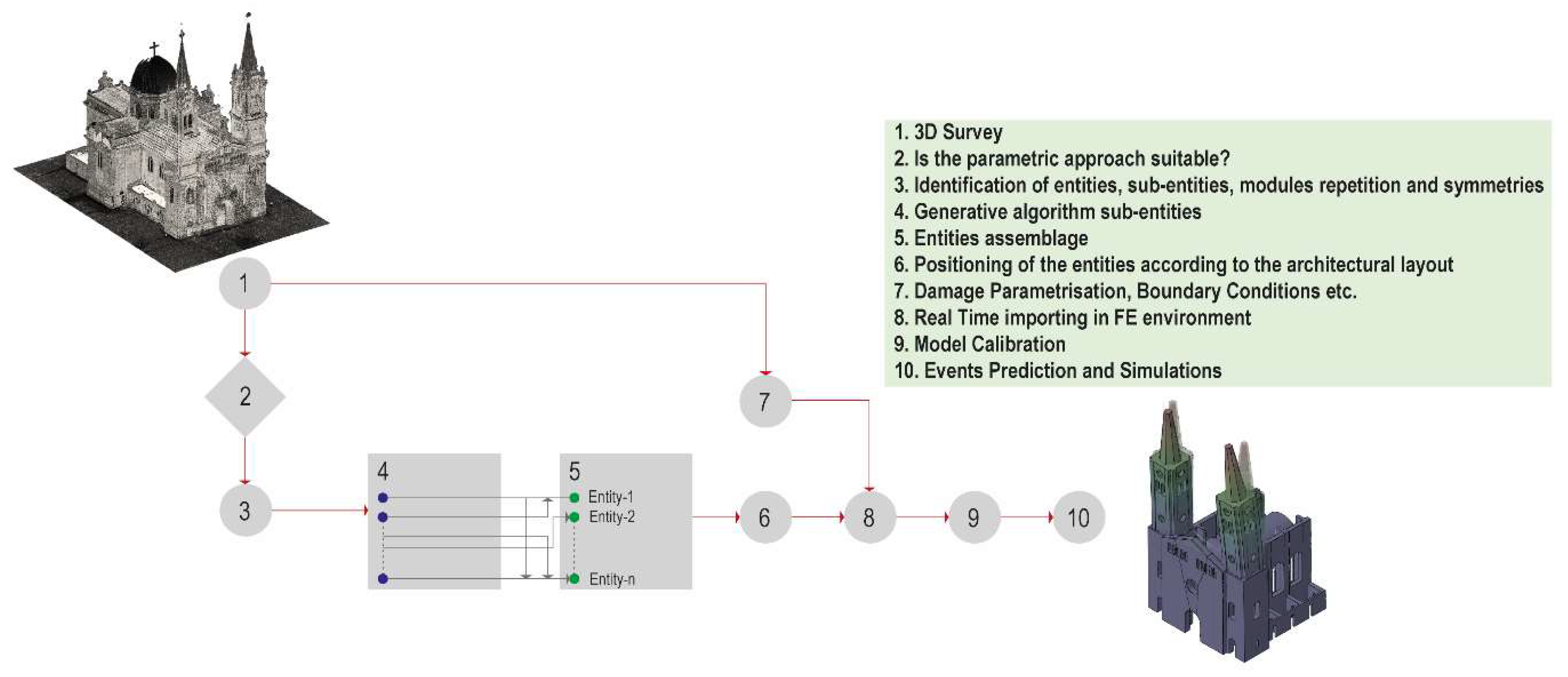
Figure 4 schematises the proposed methodology workflow, whose steps are specified in the green box.
Once the acquisition of the point cloud is performed, the geometry of the case study is analysed in order to discern whether it could be parametrically discretised by identifying (i) entities, (ii) sub-entities, (iii) modules repetitions, and (iv) symmetries. Afterwards, the geometry of the sub-entities is parametrised by means of a proper generative script. Next, the sub-entities are assembled in the entities and allocated in specific positions following the architectural layout of the analysed structure. Finally, the geometry of the church and the elastic parameters of the materials are retrieved into an ad hoc pre-compiled Python script that runs within Abaqus program to assemble the FE model in no time.
3.1. Identifying, Coding and Assembling for Entities and Sub-Entities
The purpose of this study is not to perform a stone-by-stone digital representation of the analysed structure; metric and morphological values are both deemed important in global terms, but elements are represented by their overall ideal geometry without differentiating among the single constitutive materials (e.g., walls are represented as unique shapes and units are not distinguished). On the contrary, secondary elements such as windows, architectural decorations or furniture are not considered in the model due their structural irrelevance.
Hereafter, the library of entities defining the architectural layout of the monument is presented. This identification step (node 3 in
Figure 4) is currently performed by hand, though future developments may include the adoption of other criteria to discretise the building in entities and sub-entities, e.g., considerations about the material homogeneity or the use of sophisticated segmentation algorithms for automatic recognition [
42,
43].
Table 1 shows some examples of architectural modules that repeat across the church. They represent the main entities of the model and are, in turn, discretised into sub-entities, namely into primary architectural elements, like columns, bases, etc.
In order to perform the Scan-to-FEM migration of each sub-entity (node 4 in
Figure 4), the algorithm reported in
Table 2 has been developed. It is worth stressing again that the goal of this study is to rigorously represent the structural system of the church in order to create a 3D digital mirror suitable for structural analyses; hence ornamental details are neglected on purpose.
Referring to
Table 2, the first step consists of the identification of the primitive geometries which fit the sub-entities, e.g., hexahedra to represent masonry walls, cylinders to reproduce pillars, etc. To this purpose, the point cloud is analysed, carrying out some semi-automatic operations such as horizontal and vertical slicing to detect the NURBS curves that generate the 3D shape of each sub-entity. Hence some attributes are selected and adopted as input of the component, which gives the parametric model of the sub-entity as output. For the sake of clarity
Table 3 represents the attribute adopted to discretise the sub-entity 4.
One can note that each sub-entity needs different attributes to perform its 3D model; hence, a generative algorithm is coded for each sub-entity through the GHPython component available in Grasshopper [
30]. These components are then included in an extensive library of objects used in turn to generate the assemblage of all the entities (see
Table 1 and node 5 in
Figure 4). It is worth noting that the so-created sub-entities may also be used for other projects just by adapting their dimensions, thanks to the parametric definition ensured by Grasshopper [
30]. The concept behind the recursive use of the generated sub-entities is clearly explained in nodes 4 and 5 of
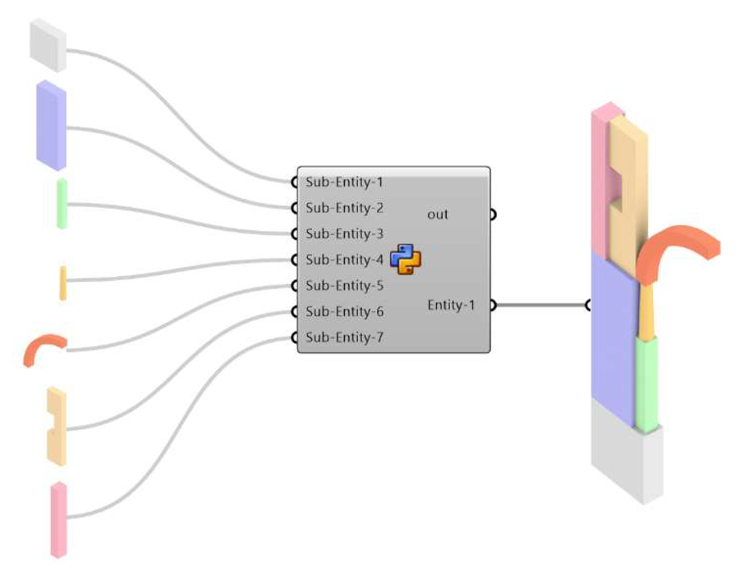
Figure 4 where the assembling of the entities is schematically represented. For the sake of clarity,
Figure 5 represents the generative modelling of entity-1, which is formed by seven sub-entities and is assembled through a proper GH Python where RhinoScriptSyntax library functions are adopted [
29,
30].
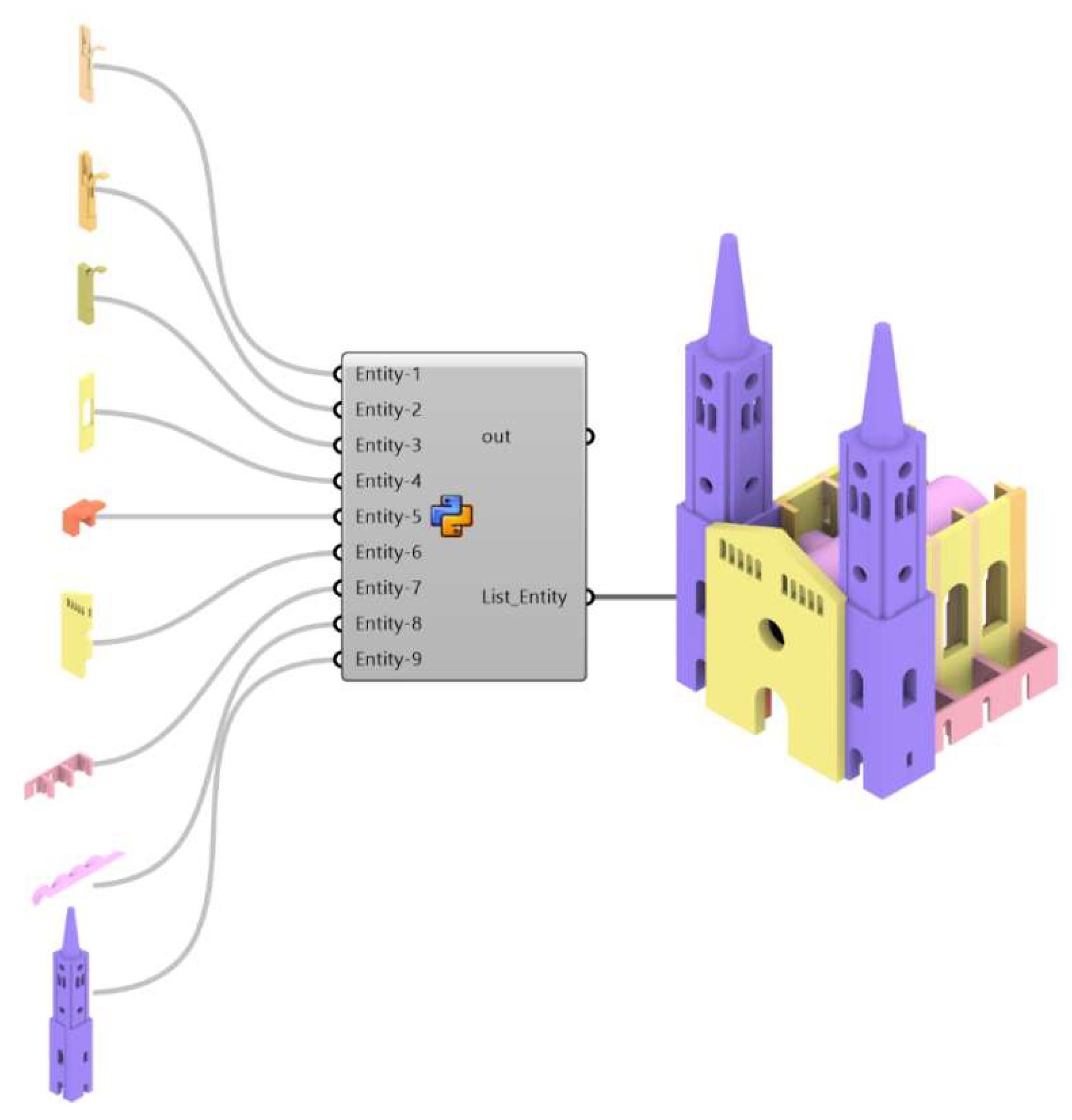
At this stage, the model generation passes through implementing the rationale rules that define the original layout of the case study (node 6 in
Figure 4). Such a stage is also performed using a GHPython script. The entities constitute the input data, and the script provides them rotated, moved, and copied to match the point cloud model. One can note that the most time-consuming step consists of the “translation” of the original architectural layout into a set of coding rules to get the full geometry of the structure (
Figure 6). A futuristic vision would be the use of artificial intelligence in order to automatise such a procedure. However, computer science is still far from achieving these results that would enormously decrease costs and processing times. As outputs, the entities are collected into a list that is used as an input for the next step, i.e., the importing process into the FE environment.
3.2. Importing Process in FE Environment
One of the main gaps still not covered in the literature is the definition of a proper tool for automatically importing the geometrical and mechanical features of three-dimensional digital assets into a finite element software. In the present work, the link between Grasshopper [
30] and Abaqus CAE [
34] is performed by using LunchBox [
44] plugin for Grasshopper [
30] along with a pre-compiled Python code, which enables a seamless connection of the parametric model to the FE environment for structural engineering purposes.
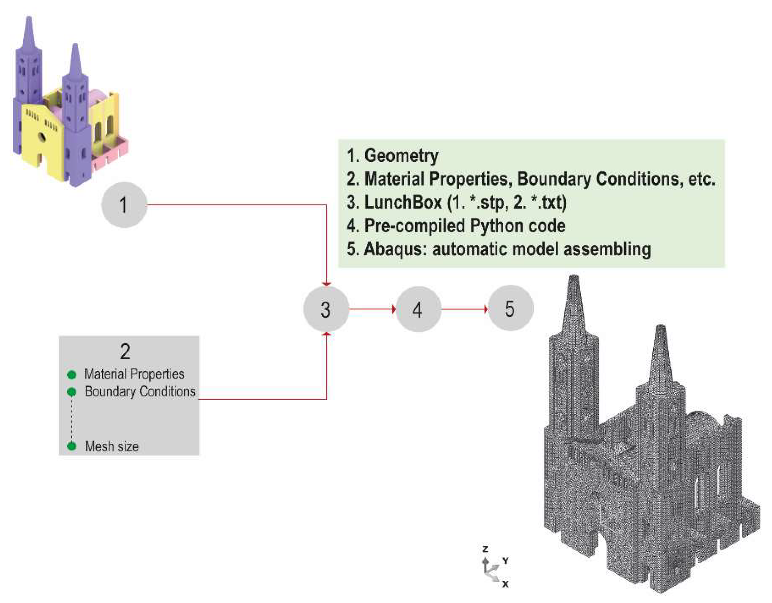
Figure 7 schematises the proposed approach. LunchBox allows us to export the full geometry of the church in .stp file format within a specific path—as well as lists containing i) the elastic properties of the single entities (which are defined taking into account the damage state of each structural part by applying penalty values), ii) the coordinates that define the position of the constraints, iii) the computational mesh size that the user wants to apply for each entity, and iv) the loads that are saved in the same folder as .txt file format. The migrated files are automatically linked into an ad hoc pre-compiled Python script that runs within Abaqus program assembling the FE model (
Figure 7).
The last node in
Figure 7 displays the assemblage of the FE model in Abaqus CAE. In this case, the time needed to run the script and obtain the assembled model is less than 2 seconds. The discretisation is achieved using Delaunay tetrahedral meshing due to its adaptability to complex geometries. Specifically, the so-called TETC3D4 elements of the Abaqus CAE library, based on a tetrahedral geometry with linear interpolation, are used. Altogether, the final numerical model results were composed of a total of 384,094 tetrahedral elements and, considering interelement continuity, a total of 91,818 nodes and 271,567 degrees of freedom.
4. FE Model Calibration
With the aim of reproducing the mechanical behaviour of the church and obtaining a reliable digital mirror, the unknown material parameters of the model are estimated by exploiting the solution of an inverse dynamic problem, namely using as reference metrics the modal properties identified from field acceleration data and calibrating the numerical model accordingly until its dynamic response matches the experimental counterpart. The results of the Operational Modal Analysis (OMA) carried out on the vibration signals collected between February 2014 and August 2015 by Masciotta et al. [
1] are employed for this purpose. The dynamic data acquisition and associated modal feature extraction covered the entire period of the structural intervention (see
Section 2 for details), thereby allowing us to assess both the effectiveness of the strengthening works and the influence of environmental fluctuations on the system’s dynamics. A total number of 4743 programmed events were processed through an automatic algorithm based on the data-driven Stochastic Subspace Identification method (SSI-data) [
1]. Details about the experimental campaign as well as the processing and analysis of field data are not discussed here for the sake of brevity, but the reader can refer to [
1] for a thorough description of the monitoring results. For the scope of the present work, only the average frequency values of the first four vibration modes estimated before and after the retrofitting intervention will be considered. It is worth noting that the positive impact of the consolidation measures is reflected by all dominant modes of the church, reading frequency upshifts ranging from 3.7% (1st mode) to 0.7% (4th mode).
The calibration of the FE model of St. Torcato Church is performed for either structure manual modal-based updating procedure consisting in the controlled variation of the values assigned to the uncertain structural parameters till the errors between experimental (measured) and numerical (predicted) frequencies are minimised. In this context, the objective function adopted for the finite element model updating (FEMU) only accounts for the first four experimental frequencies, which equals the number of material unknowns to be estimated. Indeed, as detailed next, the major uncertainties of the numerical model lied in the identification of reasonable values for the Young’s modulus of the masonry material in order to properly consider its variability in the damaged configuration of the church. The optimal mechanical parameters reported in Sánchez-Aparicio et al. [
36], which indeed refer to the original structure (nonretrofitted configuration), are here adopted as initial values for the calibration procedure (
Table 4).
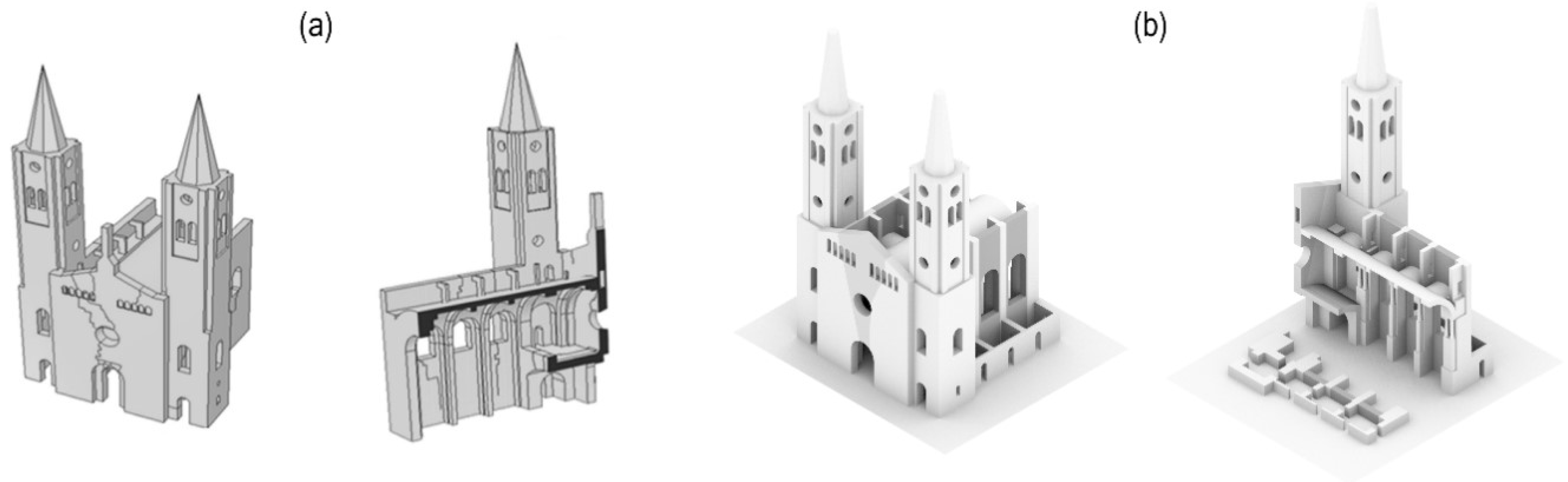
Figure 8 compares the 3D model resulting from the proposed Scan-to-FEM procedure with the one obtained by Sánchez-Aparicio et al. [
36].
The methodology proposed by Sánchez-Aparicio et al. [
36] appears more articulated and complex with respect to the proposed one. Their procedure is detailed described in ref. [
36], and it is summarised as follows: (i) hybrid point cloud registration, (ii) hybrid point cloud resampling and CAD conversion, (iii) crack recognition and characterisation, (iv) meshing algorithms usage to transform the geometrical model in a finite element discretisation.
Although ornamental details are not modelled in either case, the proposed approach provides significant improvements in terms of metrics and geometry characterisation as well as a huge amount of time needed for its generation, namely: (i) the thickness of the vaults and other structural entities is derived directly through the point clouds without resorting to any manual indirect measurements, resulting into a more realistic and consistent model; (ii) there are no morphological simplifications nor underestimated dimensions in the definition of the internal structural entities, e.g. pillars and arches, which is fundamental when aiming at a realistic model apt for structural analysis purposes. It is noted that metric issues have to be addressed upstream, i.e., when defining the acquisition protocol for the 3D digitisation of the heritage asset, as they are directly linked to the data capturing process and accuracy level. Further differences between the model herein discussed and the one present in the literature concern the approach adopted to simulate the damage of the structural elements. Sánchez-Aparicio et al. [
36] assumed an explicit representation of the cracks, where the residual cohesion was simulated using a bed of linear springs having a finite stiffness. On the contrary, the proposed approach aims to parametrise the damage as a penalty factor of the elastic modulus, which is assigned to the part(s) of the structure showing increasing displacements or signs of distress.
4.1. Calibration of the Unstrengthened Model (USTR)
The geometrical differences between the proposed approach and that one developed by Sánchez-Aparicio et al. [
36] have been reflected in the modal analysis results. Different elastic moduli and material densities values have been obtained at the end of the calibration (
Table 4).
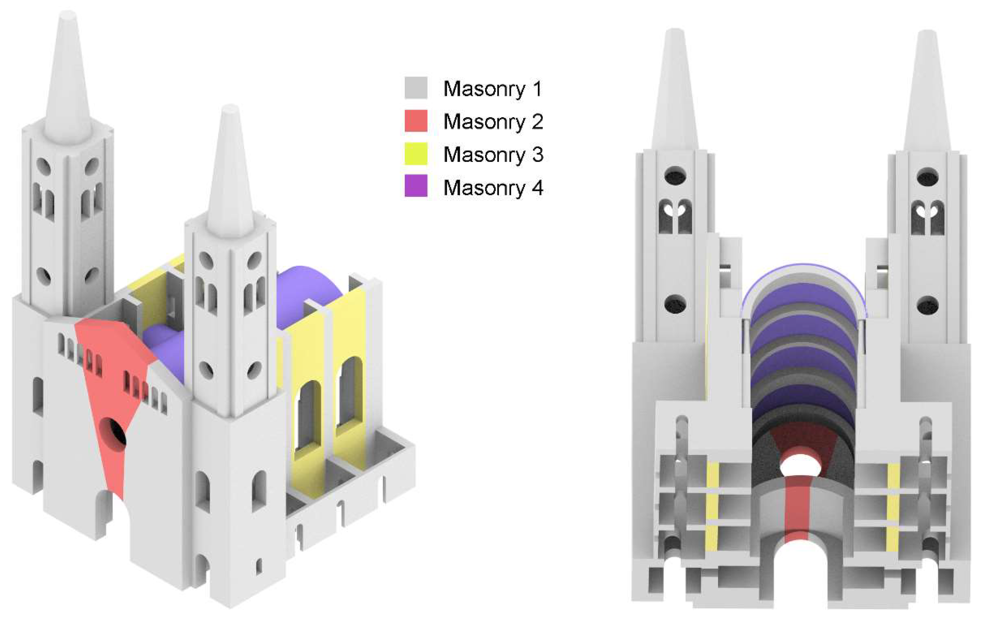
For the calibration of the unstrengthened configuration, based on the extensive information gathered from the past anamnesis and in situ investigations of the structure, the masonry elements of the FE model of the church are further grouped into four distinctive parts referred as M1, M2, M3 and M4 (
Figure 9), each characterised by an isotropic linear elastic behaviour.
Table 4 summarises the values of the mechanical parameters adopted for the USTR model: the optimal values of the Young’s modulus and of the material density obtained at the end of the calibration procedure; in regular font, the other elastic parameters—including the Poisson’s ratio which is kept unvaried throughout the updating process. One can note that the density of the proposed model has been calibrated to a value of 2000 Kg/m
3, which is more reasonable with respect to 2600 Kg/m
3 obtained in [
36]. The stiffness of the Winkler springs adopted to simulate the soil underneath the “towers-façade” system as well as the interfaces between longitudinal body and transept features values of 0.65 and 50 GPa m
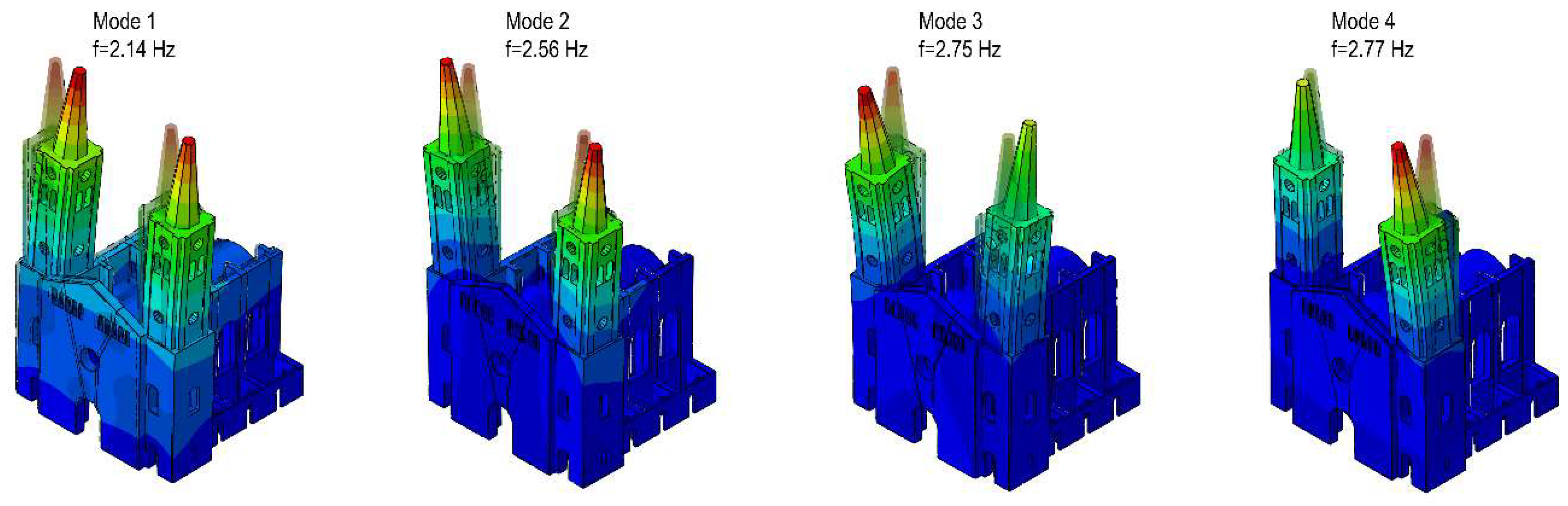
-1, respectively. The modal results of the calibrated numerical model are displayed in
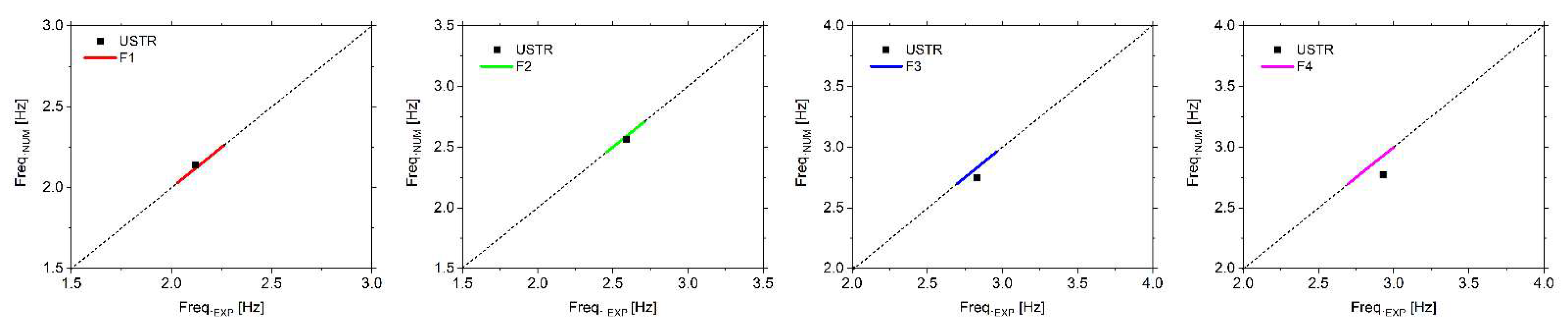
Figure 10 in terms of mode shapes and corresponding frequencies, whereas
Table 5 reports the comparison between numerical and experimental outcomes along with the relative percentage errors. It is worth noting that a very good correlation is found between predicted and measured frequency values, especially for the first two modes, as the plots around the target diagonal fitting line demonstrate (
Figure 11). The greater scatter featured by the fourth mode is likely due to the absence of coordinate-dependent modal comparative metrics, which are pivotal to improve the degree of correlation of higher modes. Still, the estimated value falls within the statistical range resulting from the long-term monitoring campaign reported in [
1].
4.2. Calibration of the Strengthened Model (STR)
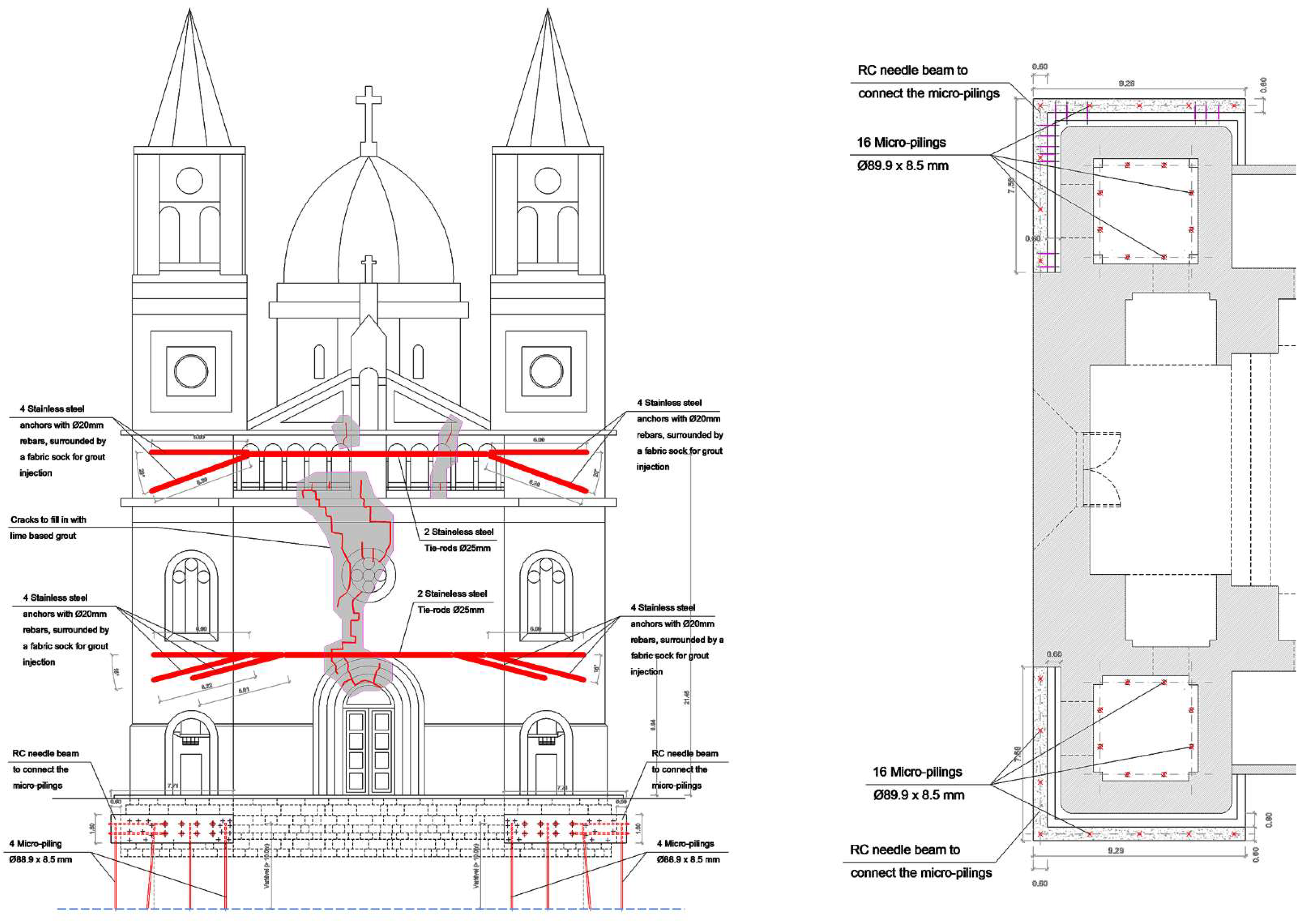
The calibration of the strengthened configuration of the church is performed using the USTR model as baseline and adding the retrofitting measures executed during the structural intervention of 2014–2015. Particularly, the following strengthening systems are included in the model:
Anchoring system: the steel chains restraining the towers are explicitly modelled by using beam elements characterised by a circular cross-section of 25mm diameter and a modulus of elasticity equal to 210 GPa.
Micro-piles system: the micro-piles effect is implicitly simulated by increasing the value of the Winkler spring stiffness distributed below the towers and the façade.
Crack injections: the restored “material continuity” is simulated by rationally decreasing the penalty factors that affected the part of the structure where cracks were injected.
Given the aim to assess the church dynamic behaviour in its retrofitted condition, the model updating procedure is carried out by keeping unvaried the four-group ideal subdivision of the linear isotropic FE model and assuming as initial moduli of elasticity the optimal values estimated for the calibrated USTR model. With regard to the Winkler spring stiffness simulating the soil underneath the “towers-façade” system, an increase of 25% is applied, as previously mentioned. Similar to the USTR case, the objective function to be minimised does account for the residuals between numerical and experimental frequency values of the first four modes. It would have been desirable to include also the mode shapes information in the model updating process; however, reference experimental modal vectors were not available.
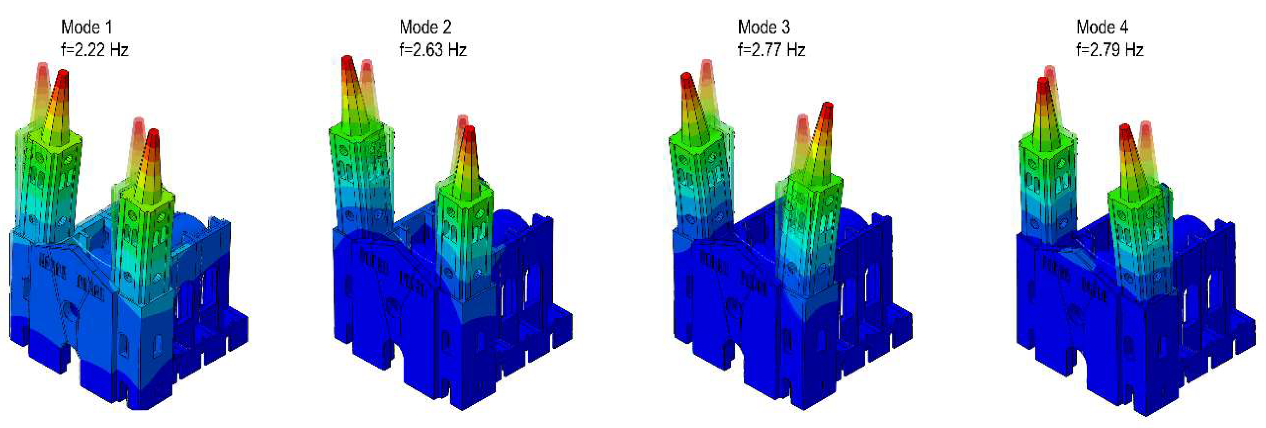
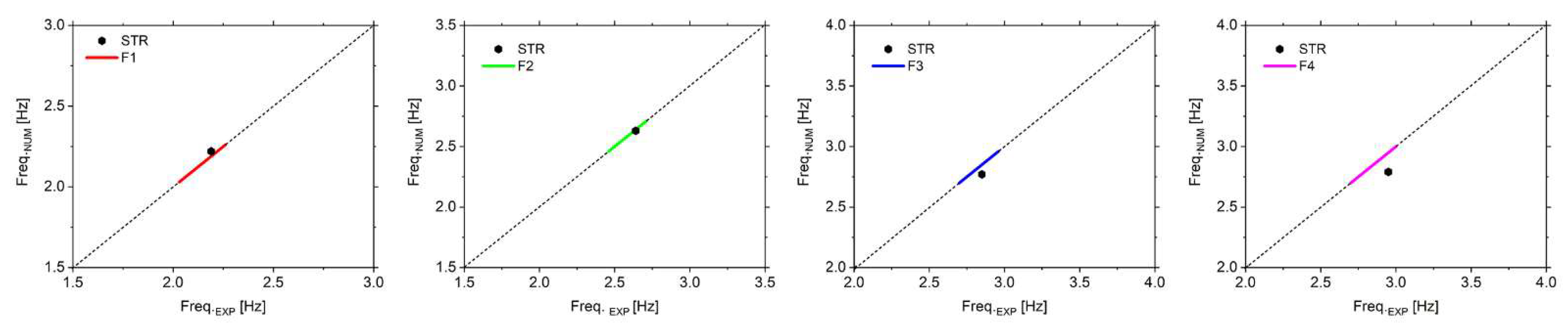
Table 6 summarises the mechanical parameters of the masonry material of the STR model, including the optimal values of the Young’s modulus obtained at the end of the calibration procedure. As for the modal results,
Figure 12 illustrates the mode shape configurations of the first four vibration modes of the retrofitted church, while the direct comparison between numerical and experimental frequencies is given in
Table 7, along with the relative percentage errors. The visual comparison with the unstrengthened counterpart clearly highlights the degree of similarity existing between mode shapes before and after the structural intervention, though frequencies increase with a percentage ranging from 3.7% to 0.7% (
Table 8), which is in good agreement with the range estimated by Masciotta et al. [
8] through SHM-data. In particular, the first two modes are mainly affected by the interventions, i.e., +3.7% and +2.7%, because the strengthening design was devoted to locally increasing the towers’ stiffness and decrease their relative movement.
Table 8 also represents the MAC values between the USTR and STR numerical models. For the sake of completeness,
Figure 13 gives a visual insight into the frequency upshifts featured after the structural intervention by the first four modes of the church, both experimentally and numerically.
6. Final Remarks
This paper presents a parametric Scan-to-FEM procedure based on the use of the GP paradigm implemented in a visual programming environment. Such an approach is particularly suitable for structures characterised by symmetries, repetition of modules and architectural orders, making the Scan-to-FEM transition fast and efficient.
The proposed algorithm was implemented within the visual programming environment offered by Rhinoceros3D + Grasshopper, and Python scripts were used to automatise some procedures in order to improve the efficiency of the proposed workflow.
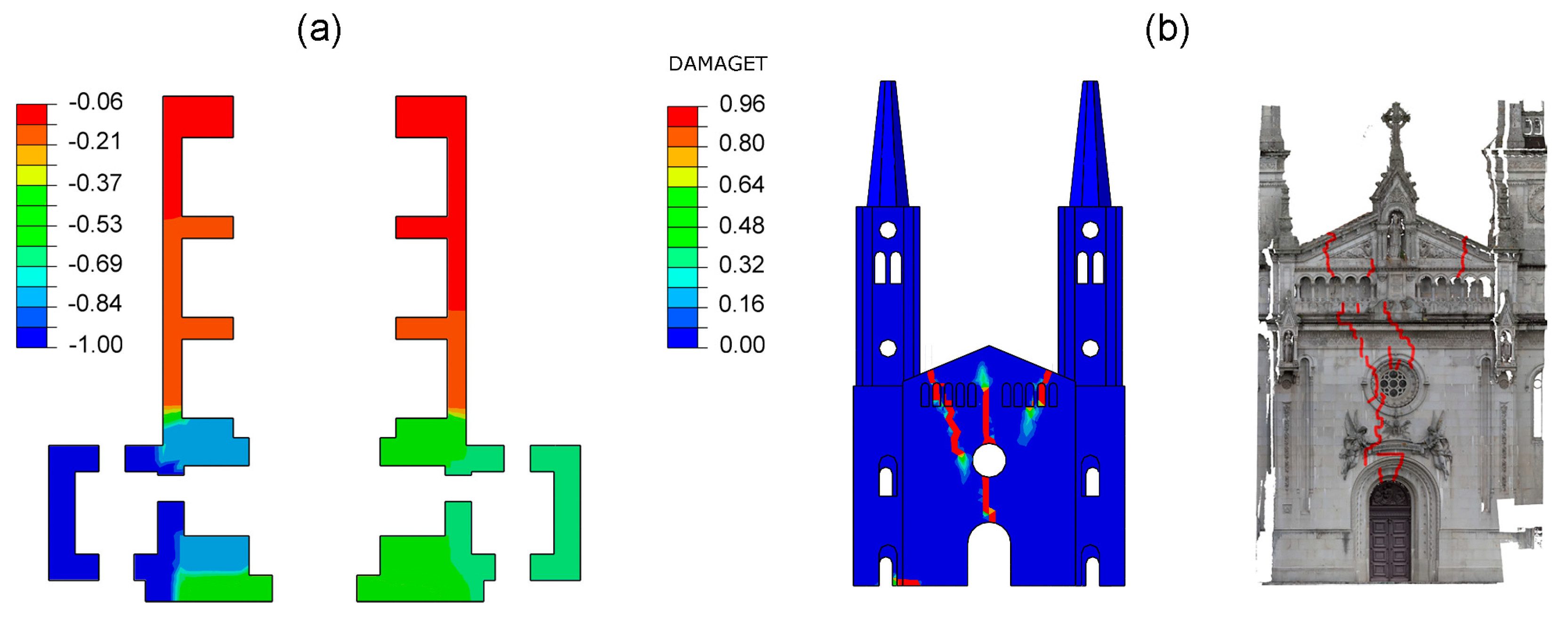
A digital replica of an important Portuguese monument was developed. In particular, the calibration of the associated FE model was performed. To this purpose, the unknown material parameters of the model were estimated by fitting the modal properties identified from field acceleration data and calibrating the numerical model accordingly until its dynamic response matched the experimental frequencies. Furthermore, the calibration was performed according to two structural configurations, i.e., USTR and STR, to estimate the effectiveness of the retrofitting interventions performed in 2015. Finally, the validation of the digital model was assessed by means a foundation settlement simulation that involved the monument and generated the tilting of the towers and an extensive damage pattern of the façade.
From this study, we can conclude the following:
GP paradigm is an efficient approach to perform the Scan-to-FEM migration of historic masonry structures when their architectural layout is featured by the repetition of modules, symmetries, etc.
The proposed approach is quite efficient from the computational point of view, being able to perform the transition from half-raw survey data (point clouds) to geometrical entities in nearly no time.
The library of sub-entities can be easily adapted for the model generation of other historic masonry structures.
A performant solution for the automatic link between the visual script and FE environment was implemented, developing a pre-compiled Python script that is able to assemble the FE model in few seconds.
The calibration of the FE model was started by assigning the elastic modulus and the density by Sánchez-Aparicio et al. [
36] to all the parts of the proposed model. Then, the elastic modulus and the density of the parts have been calibrated to achieve a good correlation between numerical and experimental frequencies.
The strengthening interventions were able to slightly increase mainly the first two frequencies of the St. Torcato church within a percentage in agreement with the OMA.
The calibrated FE model was able to simulate the damage pattern caused by the foundation settlement accurately.
Future developments will include the introduction of (i) sophisticated segmentation algorithms for the automatic recognition of entities and sub-entities and (ii) for the identification of the architectural layout of the building in order to perform a more efficient modelling process. Furthermore, the entities and sub-entities created could be made freely available for users involved in other projects.


 ,
, 


