Digital Twin for FANUC Robots: Industrial Robot Programming and Simulation Using Virtual Reality


1
Institute of Technology, Robotics and Computer Engineering, University of Tartu, 50090 Tartu, Estonia
2
Department of Mechanical and Industrial Engineering, School of Engineering, Tallinn University of Technology, 19086 Tallinn, Estonia
3
Department of Intelligent Computer Vision (iCV), Institute of Technology, University of Tartu, 50411 Tartu, Estonia
4
Institute of Higher Education, Yildiz Technical University, Istanbul 34349, Turkey
5
PwC Advisory, FI-00180 Helsinki, Finland
6
iVCV OÜ, 51011 Tartu, Estonia
*
Author to whom correspondence should be addressed.
Sustainability 2021, 13(18), 10336; https://doi.org/10.3390/su131810336
Submission received: 5 July 2021
/
Revised: 2 September 2021
/
Accepted: 10 September 2021
/
Published: 16 September 2021
(This article belongs to the Special Issue Mechatronics Technology and Transportation Sustainability)
Abstract
:A Digital Twin is the concept of creating a digital replica of physical models (such as a robot). This is similar to establishing a simulation using a robot operating system (ROS) or other industrial-owned platforms to simulate robot operations and sending the details to the robot controller. In this paper, we propose a Digital Twin model that assists in the online/remote programming of a robotic cell by creating a 3D digital environment of a real-world configuration. Our Digital Twin model consists of two components, (1) a physical model: FANUC robot (M-10iA/12), and (2) a digital model: Unity (a gaming platform) that comes with specialized plugins for virtual and augmented reality devices. One of the main challenges in the existing approach of robot programming is writing and modifying code for a robot trajectory that is eased in our framework using a Digital Twin. Using a Digital Twin setup along with Virtual Reality, we observe the trajectory replication between digital and physical robots. The simulation analysis provided a latency of approximately 40 ms with an error range of −0.28 to 0.28 across the robot joint movements in a simulation environment and −0.3 to 0.3 across the actual robot joint movements. Therefore, we can conclude that our developed model is suitable for industrial applications.
1. Introduction
At present, nearly all industrial simulation software is based on an offline simulation, where we set up the simulation environment and generate a program, which can be transferred to a physical system [1]. However, the programs developed through offline simulation environments lack accuracy, which results in time-consuming rework overhead on physical models [2]. To overcome this limitation, the Digital Twin comes with the Online Simulation, allowing one to connect with the robot and move it along the desired path on the simulation screen and actual model.
However, one of the challenging tasks of these Digital Twin models is to create and connect them with the actual model, as this requires a well-defined digital 3D structure [3]. Generally, for industrial purposes, CAD software for 3D modeling is used. However, at present, CAD software does not support file formats, such as filmbox (.fbx), collado (.dae), that are supported by game engines [4].
Game engines are proven to be excellent in terms of graphics displays [5]. The level of detail that can be shown or designed on gaming platforms is one of the missing components from existing industrial simulation software present in the market. In addition to their enhanced graphics, these game engines provide an excellent environment for generating synthetic data. For example, gathering data for an artificial intelligence (AI) model for pick and place applications under different illumination intensities is a time-consuming and challenging task in a physical environment. However, on a gaming engine, all it takes is an understanding of ray-light interaction, and then a large amount of training data for the AI model can be generated in a short period of time.
In this work, we created a digital setup of a FANUC robot. The developed digital model has the capability to generate the program for the actual robot setup. One can argue that there are already many simulation software programs present in the industry that can help to create a program, but they come with an additional cost or are limited to a single robot type. To overcome these limitations, gaming engines for industrial applications have been utilized, which comes with prepacked packages for integration of Virtual, Augmented, and Mixed Reality devices from different manufacturers that are missing in the available simulation software.
1.1. Highlights
The work in this paper covers the following:
- (1)
- Digital Twin model: Developed a digital 3D model using Unity (game engine) that generates a program for the physical robot (PR). In particular, we used the FANUC robot model M-10iA/12 and tested the program on the PR (Section 3.2.1).
- (2)
- Communication Setup: Established a communication channel between Digital and PR for exchanging required data, such as joint angles and actual robot status signals (Section 3.2.7).
- (3)
- Virtual Reality (VR) Interface: Created a VR environment on the Unity platform. For visualizing the VR environment, we used the HTC VIVE VR device (Section 3.2.8).
1.2. Contribution
The contributions of this research work are three-fold:
- (1)
- The key contribution of this paper is that we developed a Digital Twin model of an industrial robot, which helps in controlling a PR in synchronization with a digital model for a desired robot trajectory. This is usually done offline or manually [6,7,8]. However, using our framework, the trajectory points are stored locally or sent online/remotely via a real-time communication setup.
- (2)
- Next, we surveyed to check the ease of robot programming using our model. The participants found that the created virtual environment is interactive and easy to use for robotic operations. On average, participants rated 3 on a scale of 0–10, where 0 means very easy and 10 represents highly difficult.
- (3)
- In certain works [9,10], twin models in robotics were also developed using a game engine environment; however, the same platform (DOT NET to DOT NET) was used for data exchange/controlling. However, we developed communication across two different platforms (Dot Net to KAREL) as a part of our effort.
1.3. Organization
The rest of the workflow is as follows. Next, we discuss the related work. Then, the methodology includes a description of devices used in this work along with our proposed model in Section 3. The results and analysis of the experimentation are presented in Section 4. In Section 5, we discuss the sustainability of the developed solution and highlighted some use case scenarios. Finally, a conclusion with a discussion of future directions is covered in Section 6.
2. Related Work
For the last two decades, researchers have been working on the development of Digital Twin models. However, this has recently attracted a lot of attention, and work is being done in a variety of research industries ranging from medical to the industrial manufacturing sector as, unlike other simulation environments, it provides two-way communication between physical and digital robot models along with a 3D view of the environment.
A Digital Twin maps a physical object or process with a digital environment that enables simulation, education [11,12,13], prediction, and optimization [8,14] and helps in product design and simulating manufacturing systems [15,16,17,18], and processes [19]. Robotic applications [20] are the specific area of the Digital Twin domain, focusing on the ease of programming.
In [21], the authors conducted an experiment with Mixed reality (MR) for interactive robot programming. The researchers further compared the MR with VR and created a framework to program different shapes using MR. In another work [22], the authors proposed a model that encapsulates offline robot programming with VR. However, this work used external magnetic sensors to generate the program. In another similar work, [23], communication was established between the KUKA robot and VR device over a Modbus TCP/IP interface. The authors tested the feasibility of controlling a robot; however, work for defining the complete trajectories was missing.
In another line of work, research groups from the University of Oviedo and the Idonial center of Technology created a Digital Twin of a manufacturing cell [24] and studied the effectiveness of Digital Twin for robotic applications with various parameters, such as acquisition costs, robots from different manufacturers, human–robot collaboration, virtual reality, environment customization, usability for training.
Since Industry 4.0 is in high demand [25,26], this research is moving towards the creation of intelligent and resilient systems. The study shows an implementation of a knowledge-driven Digital Twin manufacturing cell (KDTMC) [27]. KDTMC approach targets an intelligent manufacturing system that supports autonomous manufacturing by integrating perception, simulation, prediction, optimization, and controlling strategy. This work utilizes the Digital Twin to study the manufacturing cell and integrate intelligence into it.
In addition to this, there have been different approaches and methods used by other researchers for the implementation of a digital twin. In a recent paper, a research group conceptualized a digital twin with a five-dimensional framework [28] that represents the complex relationship between digital twin objects and their attributes. In another work, a reference model for a digital twin was introduced, where it is provided as a service, Digital Twin as a Service (DTaaS) in Industry 4.0 [29]. As the manufacturing sector is focusing on optimizing energy consumption, the researcher worked on utilizing a digital twin for implementation of Industry 4.0 in the field of construction as well as smart cities with a primary focus towards optimizing the energy consumption and maximizing productivity [30].
In our experimentation, a PR is controlled via a digital model that operates in the virtual environment. There are certain robot status signals that are being captured and are necessary for any twin model, which are not mentioned in the existing literature. Additionally, this work has elaborated more on the controlling algorithms used in the physical and digital setup, compares the joint movement, and visualizes the errors between guided and executed joint angles.
3. Methodology
3.1. Experimental Devices
Here, the experimental setup is explained, which includes two components. The first component is a Robot. In this experimentation, we used the FANUC robot. The second main component of this setup is the VR controller, for which the HTC Vive VR device was used.
3.1.1. Robot
In this work, the FANUC robot model M-10iA/12 is used for experimentation. This is a hollow arm design that provides space for cable integration inside robot arm links rather than outside [31]. Such design protects the cables from wear and tear, making maintenance more manageable and lowering maintenance costs. Another benefit of the hollow arm is the high productivity and shortened cycle times due to the rigid arm and servo motors by allowing increasing speed during operation. The specifications and other information related to robot joint speed and robot motion range are shown in Table 1.
Table 1 column-1 shows the robot specifications like the number of axes is 6, the mass of the robot body being 130 kg, its lifting capacity is 12 kg, etc. The lifting capacity is a sum: (end effector/gripper weight+ component weight). The end effector/gripper is an attachment to the sixth axis of a robot, and its design depends on the type of application a robot has to handle. The component weight is the object weight that the robot needs to lift using its end-effector/gripper. Individual joints speed limits in mm/s, and rotation limits in degrees are also defined in Table 1 columns 2 and 3, respectively.
3.1.2. VR Device
The next main component of this experimental setup is a VR device. HTC Vive is a Virtual Reality (VR) device that is used to project a virtual environment. The virtual environment is developed digitally. In this case, we developed a digital environment for a robot using a Unity platform. There are many VR devices that are available in the market, such as Oculus Rift, HTC Vive, Valve, and Sony. Each year there have been continuous improvements in graphics and controls using VR devices in virtual environments.
As in this case, we used HTC Vive due to its availability in our lab. In particular, we are utilizing the HTC Vive VR device [32]. However, any VR model can be used for a virtual environment projection. The two main units of any VR device are:
- (1)
- A central Head-Mounted Device (HMD) unit equipped with a camera: This unit helps in immersing a digital view into the real world. It acts as an eye in a virtual environment and helps to visualize the virtual scenes.
- (2)
- Handheld controllers: To perform any action in the VR world, controllers act as a human hand. The actions defined in SDK of Vive are defined similarly to our daily routine work with human hands, such as grab, hold, button push, etc.
Table 2 shows the specifications of the VR device [33]. The “Field of View (FOV)” defines the range covered with cameras that are mounted in HMD. In this device, a single camera is embedded in HMD. However, in the newer version, two cameras are used to increase the FOV. The HMD refresh rate defines the virtual view capturing rate, and the “pose refresh rate” defines the rate of capturing pose actions performed in a virtual environment using a handheld controller, which is 4 ms (milliseconds). To create a specific action or to interact with objects in a VR environment, SteamVR is used.
SteamVR is an interface that comes along with its software development kit (SDK) that provides an extensive library to assign and read controllers actions, such as grabbing components, hitting an object, teleporting, and many other human body actions. These can be implemented by using this SDK inside the VR environment [34].
3.2. Proposed Framework
Here, we discuss our architecture for establishing a twin model. A twin model consists of two sections, the Physical and Digital sections. A Physical section consists of a PR, which is manufactured by robotic companies. A few examples of manufacturer of industrial robots are FANUC, ABB, and KUKA, that produce PR. In this work, we created a Digital Twin of the FANUC robot. Our work mainly focuses on the digital section, as it is a main missing component for creating a Digital Twin for industrial robotics. However, a PR still requires scripts development to control and communicate with a Digital Twin. The digital section includes creating a digital replica of a PR, with which we can control or program a PR.
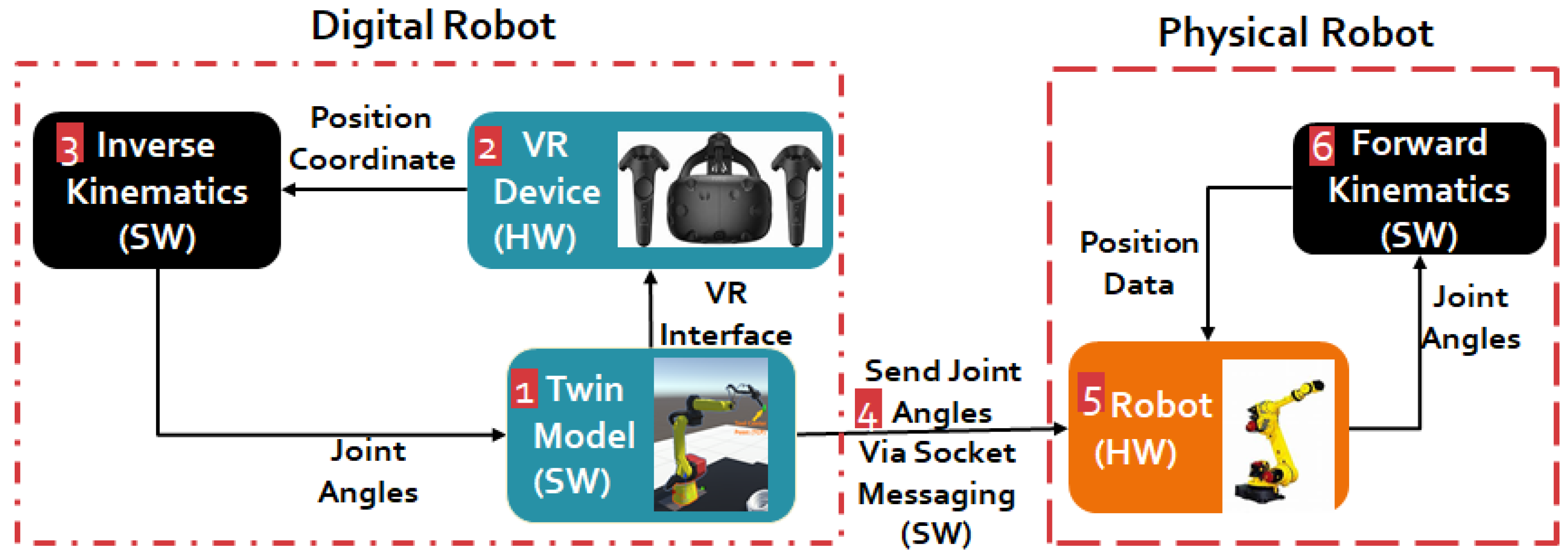
Figure 1 shows the architecture that defines the steps of creating a digital model and establishes communication between PR and digital robot. Our model of DT is divided into two main sections:
- (1)
- Digital Robot
- (2)
- Physical Robot (PR)
The components of both sections can be divided into two categories; hardware and software. For example, in Figure 1, the HTC Vive device is a hardware component (HW) that is used in the Digital section, whereas Inverse Kinematic is a software component (SW) that is used to calculate the joint angles of the robot for its desired movement. The layout is explained in six steps as follows:
- In step-1, we create a digital model of a robot that controls the PR. The gaming platform is used to set up a digital model, and the process of creating a digital model is explained in Section 3.2.1.
- Once the digital model is established, we need to provide a VR interface using a VR device. The VR interface is programmed through the OpenVR package of the Unity platform. This VR device controls the robot movement of both digital and PR.
- When a VR controller moves in the digital environment, it generates a position value for the movement of a robot arm. This position value is fed to BioIK, which is provided via Unity assets, for calculating inverse kinematic (IK). The IK generates the joint angles for individual robot joints to reach the position defined by the VR controller.
- After generating the joint angle values, these values need to be communicated to PR to move it to the desired position as defined by the VR controller. This is achieved with the help of socket messaging. Socket messaging is a server-client communication channel created in this work between a digital model and a PR.
- The FANUC PR supports the KAREL programming language. Therefore, the coding for establishing communication (Digital model and PR) and replicating VR movements in PR is done in KAREL.
- Once a PR receives the joint angle data, it is processed with the help of Forward Kinematics (FK). FK converts the joint angle data to position data in a 3D space. Finally, this position data is transferred back to the PR.
3.2.1. Creation of Digital Model
As mentioned earlier, a digital model is a digital replica of a PR. To define this replica, we first create a 3D drawing of a PR, also known as a CAD model. Almost every robotic company provides a CAD file of their robot. This CAD file includes the details of the dimensions of robot links and the position of joints between these links. The CAD file can be extracted in CAD software, such as SolidWorks or CATIA.
In our experimental setup, to create a digital model, we need to project the CAD file in a gaming engine. However, this CAD file cannot be imported directly into a gaming platform. There are specific details, such as parent–child relation and pivot point (for details refer Section 3.2.2), that have to be added to CAD drawing to use it in a game engine (Unity game engine or Unity is considered in this work). Such details can be added by using computer graphics software like Blender/Maya 3D. In this work, we employ Blender computer graphics software to incorporate additional details into the CAD file.
3.2.2. CAD Rendering in Computer Graphics Software
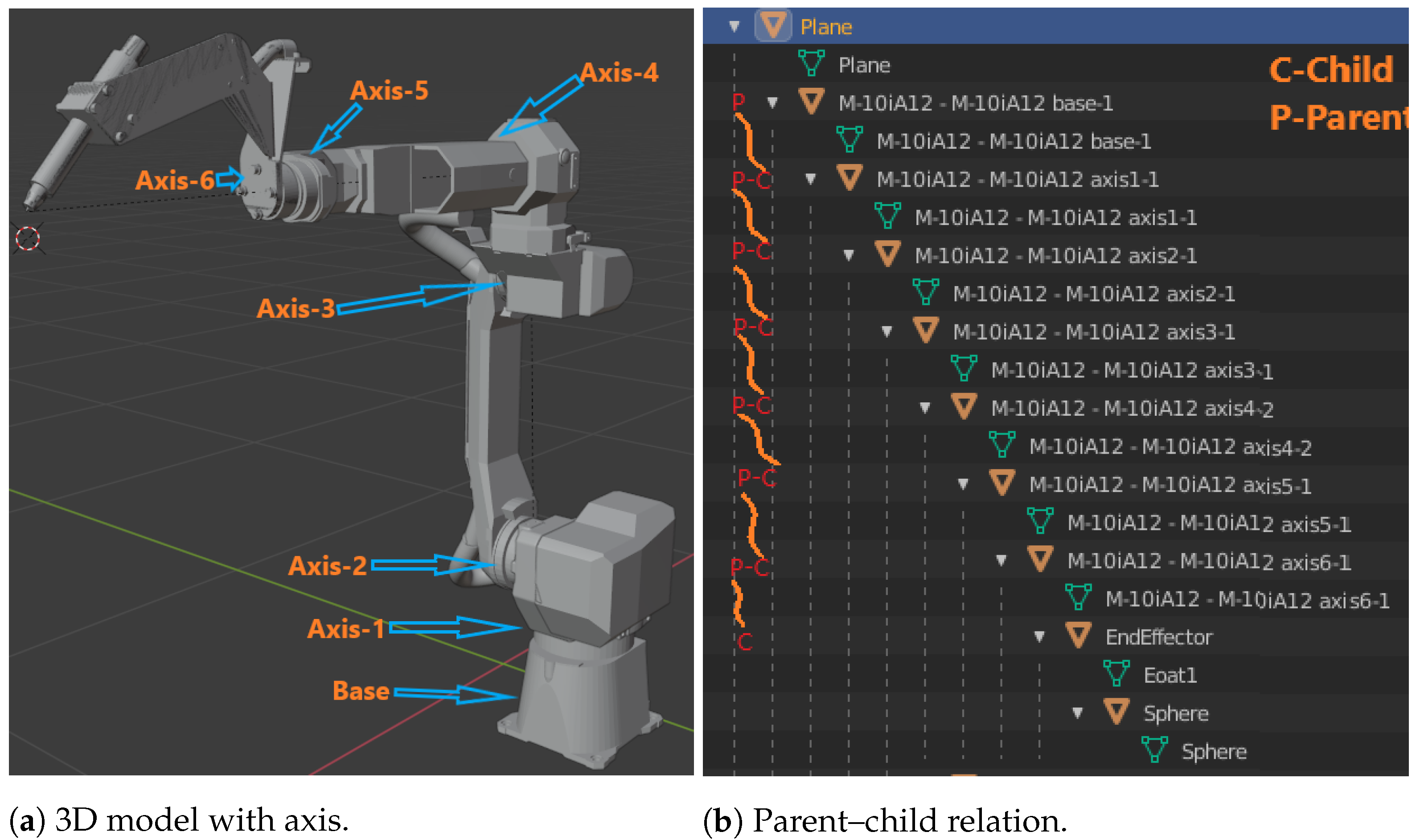
This work utilizes a FANUC Robot model M-10iA/12 (already discussed in Section 3.1.1). As discussed, to create its twin model, we first need to process its CAD file. The CAD file of the robot is accessed in SolidWorks and exported in stl format, which is accepted by blender software. In a blender, the Parent–Child relationship is defined, where the Base is a parent, and consecutive links are the child to it. Figure 2a shows a 3D model in the blender, and all the six-axis/links (Axis-1, Axis-2, Axis-3, Axis-4, Axis-5, and Axis-6) are marked. In Figure 2a, “Base” is also marked, which is a parent to all the links.
“Axis-1” is a child to “Base” and parent to “Axis-2”, and a similar parent–child relationship exists among other axis/links. This parent–child relationship is established in blender software. A tree structure of parent–child relationships among links is shown in Figure 2b. The concept behind establishing this relationship is to control the movement. For example, if we rotate “Axis-1”, then rest all links from “Axis-2” to “Axis-6” will move along with it, as “Axis-1” is defined as a parent to “Axis-2” to “Axis-6”, but it will not affect the movement of the Base. However, if we move Base, the entire model will move along with it.
In addition to the information mentioned above, the pivot point of each link must be specified. A pivot point, also known as a joint central point, is a point around which the motion of a link is defined [35]. Thus, the parent–child relation specifies the movement of the links, and the pivot point represents the joint movement, forming the complete model. Finally, the defined model is exported from the blender software in fbx (film box) format.
By default, the links are pivoted with respect to the center of origin of an individual link. However, this results in the wrong move as the movements are programmed for this point. Thus, the pivot point position is corrected using Blender, as shown in Figure 3, for all six joints of the robot arm.
3.2.3. Import 3D Model in Unity
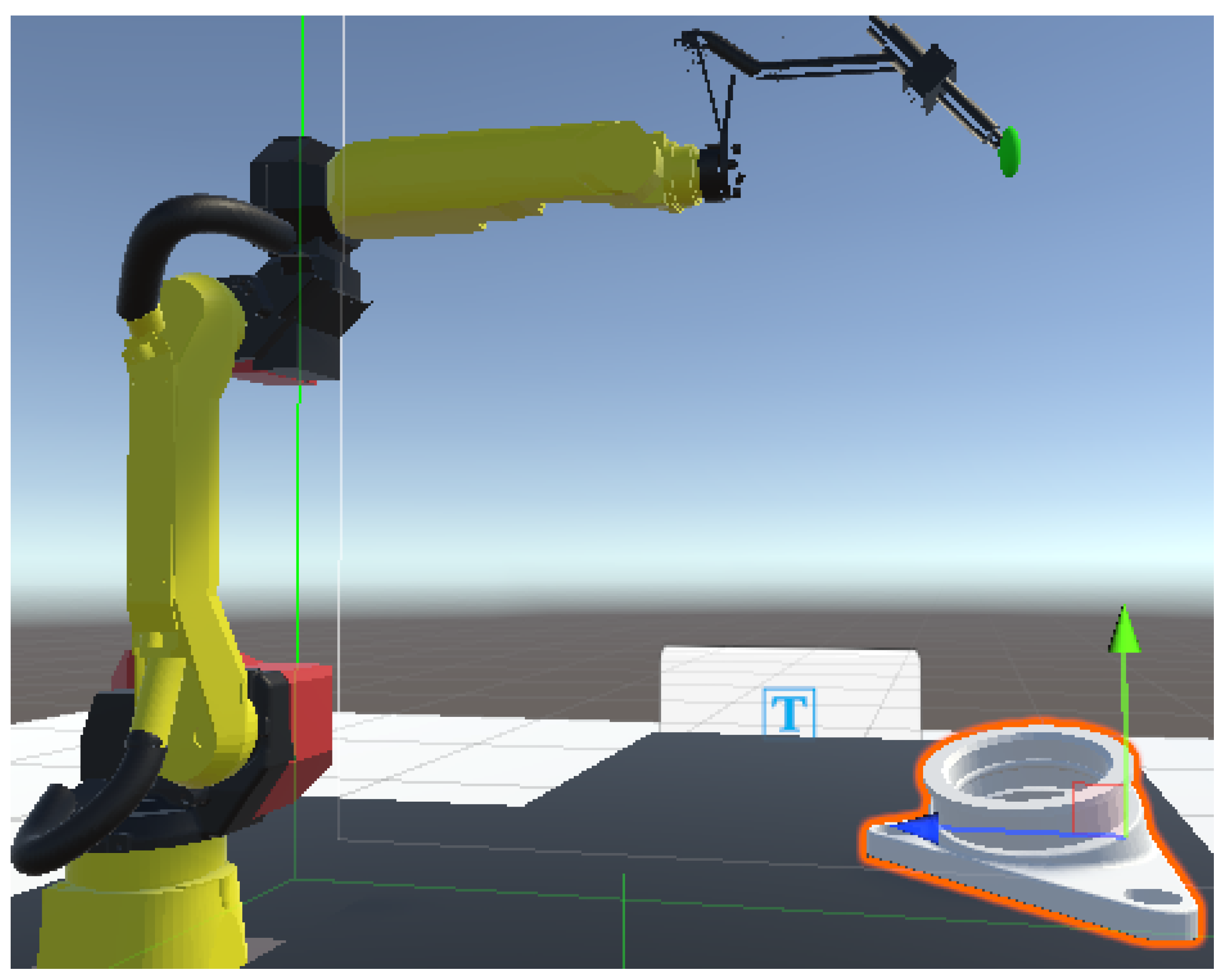
After adding the details to the CAD file in a blender, a digital model is exported from blender software in fbx format and is ready for animation and scripting inside the Unity platform. After importing the model in the Unity platform, some additional components are added to the digital robot, such as the Ground Plane, Robot Bench, Component Bench, Component, and Robot (see Figure 4). From a simulation perspective, this environment should replicate the actual robot setup. The programming accuracy is highly dependent on these additional details, e.g., the height of the robot bench, height, and distance of the component with respect to a robot. Any mismatch between the dimensions of these details can lead to errors in robot movement.
Figure 4a shows a unity environment setup. It also shows a setup of the robot with respect to its operating table (component bench). A similar setup is shown in Figure 4b, which reflects an actual robotic cell environment. In this paper, the feasibility is tested on Roboguide software. Roboguide is FANUC’s proprietary software that is used in the industry for simulation, program generation, and testing. It incorporates all the details of robot joints, starting from a joint encoder to controller details. The robot model in Roboguide software is considered as a PR in the testing environment for our work.
3.2.4. Defining Tool Center Point (TCP)
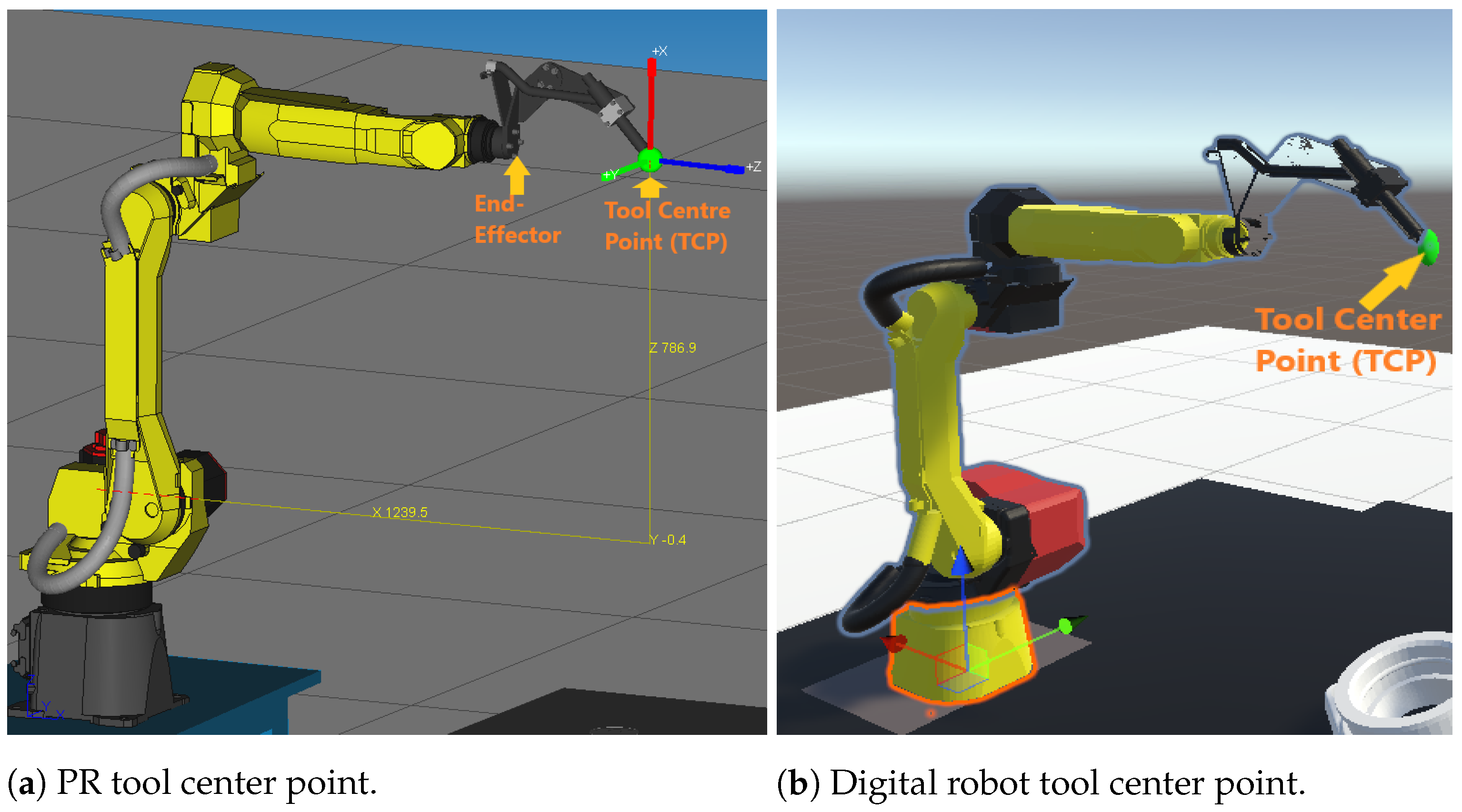
The robot model is associated with specific frames of reference in a 3D space, such as the World Frame and tool Center frame known as tool center point (TCP) [36]. The robot movement is defined with respect to its TCP, which is typically located at the center of the end-effector in most applications. The end-effector is an operational tool attached to the robot structure and performs a desired task, such as grabbing a component, welding, or some other application specified tasks. The end-effector changes as per the application. In this experimentation, we considered a welding end-effector and a TCP, which is defined at the tip of the end-effector as shown in Figure 5b.
Additional to this, in some cases, a User Frame is defined for components. The commanded coordinates for the movement of the end-effector joint can be either defined relative to the TCP or user frame. The User frame is a frame attached to the working area of the component, where components are placed for robotic operations. In this case, we tested the robotic movement with respect to its TCP. TCP of the digital model should be as close as possible to the TCP of the physical model. The closer the value, the higher the accuracy between them. Figure 5a shows a TCP of a PR, and Figure 5b exhibits the TCP of the digital model.
Here, TCP is an imaginary point that is defined as per the application and end-effector design. In this case, since the target is to control and program in the digital model, we attached a component shown in green color in Figure 5b for visualization purposes. The relative pose of the hand in a virtual environment is determined by the position of the TCP. Once we capture the digital TCP with a VR controller, the robot achieves an updated position relative to the TCP.
3.2.5. Inverse Kinematic (IK) for Digital Model
For any mechanical structure, starting from a 2-link to an n-link robot arm, an algorithm is required to calculate its joint angles to reach a specific point in 3D space, which is done using IK.
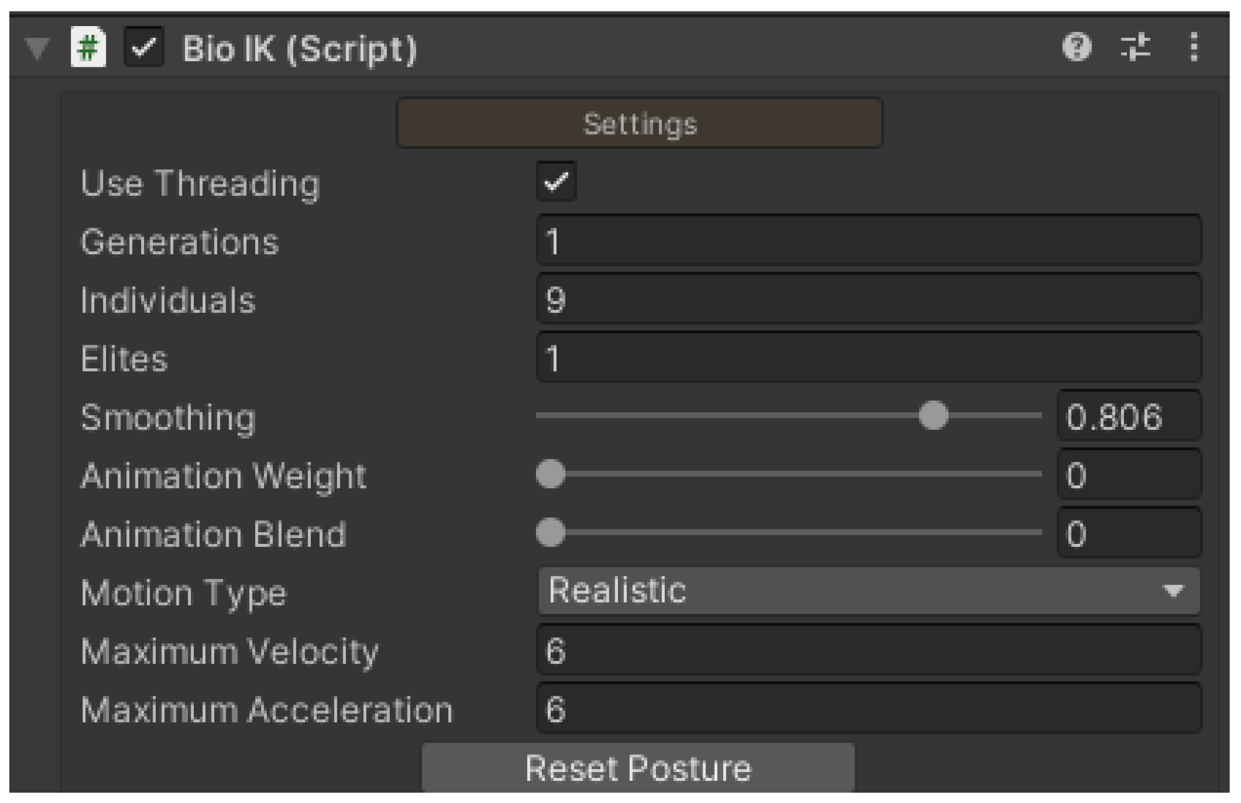
As already discussed in Section 3.1.1, in this experimentation, we used a six-link robot arm. To calculate its joint angles, the BioIK package from Unity Asset was used.
BioIK is a more dynamic single solution package, which can be plugged into any n-link model. Figure 6 shows the parameter settings for a model definition. The main parameters for this model are velocity and acceleration, which may vary for specific robot models. In this case, we refer to Table 1, column 2 (shown in Section 3.1.1), which shows the individual joint speed in radians per second (rad/s). In this case, we considered an average of 5 rad/s, and it generates data considering this value for all joints.
3.2.6. Tranform Matrix between Unity and Physical Robot (PR)
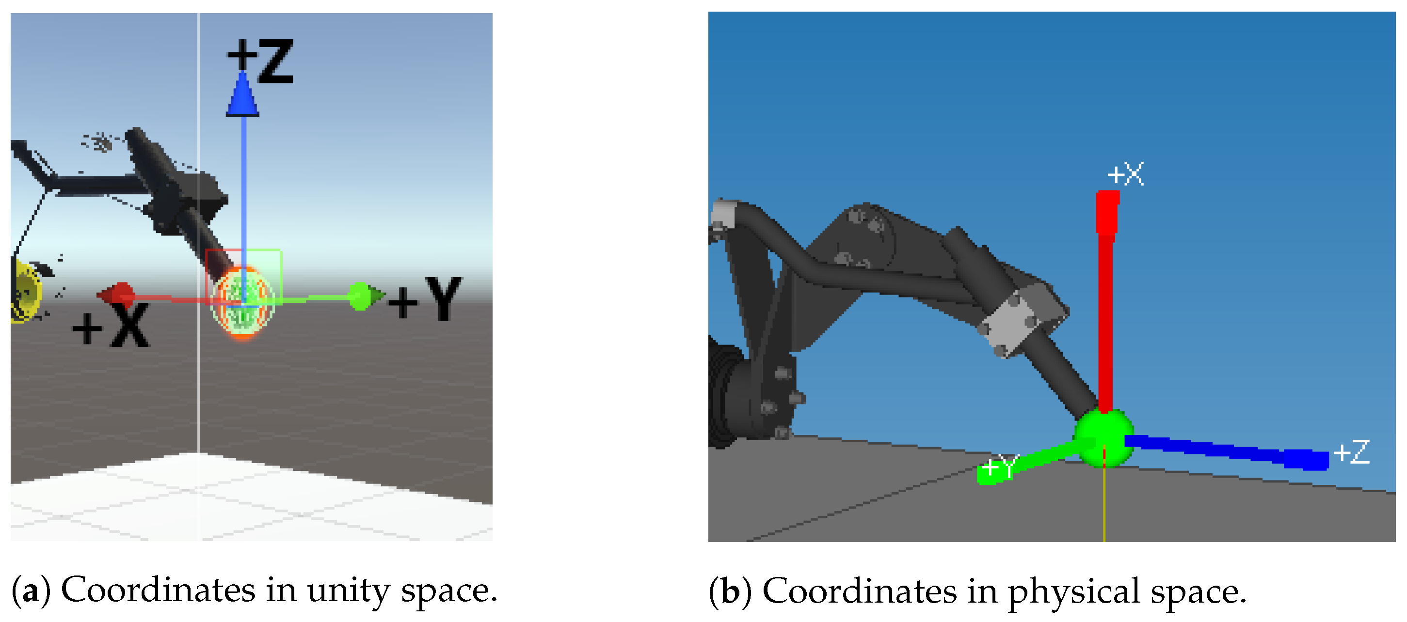
In addition to the above details, to successfully mimic the movement of a PR with its digital model we must look into the coordinate system. The model in Unity and the PR may have a different coordinate system, where Unity uses a left-handed coordinate system, Y points upward, Z points to the right and X toward the viewer with positive rotation in a clockwise direction. The FANUC robot follows different orientations Z points Upward, Y to the right, and X toward the viewer. The coordinates of both the digital model and physical model are shown in Figure 7. Here, Figure 7a shows Unity coordinate where Z is pointing upwards and Figure 7b shows X coordinate points upwards.
With the help of the transform matrix, the Cartesian coordinates of the Unity model can be transformed to Cartesian coordinates of a PR system using the Hadamard product [37,38,39] as shown in Equation (1):
where, , , and show the X, Y, and Z components of J1 joint for FANUC robot, respectively, and , , and indicate the X, Y, and Z components of the J1 joint of the Unity digital model. With the help of element-wise multiplication or the Hadamard product, we transformed the Unity Cartesian coordinates for the J1–J6 joints to PR joint coordinates.
3.2.7. Communication Channel
After establishing the digital model in the gaming engine, next comes selecting a communication link between the Digital and Physical model, which is the backbone of the Digital Twin.
FANUC robots support various communication protocols, starting from Modbus TCP/IP to Dot Net-based API. However, the types of data that can be accessed using these communication protocols are minimal. Most of the protocols support position registers, as well as digital input and output registers. These communication methods are easy to implement as a base code for this is provided by the company.
There exist another communication protocol known as socket messaging, which is based on Client-Server architecture. It is one of the oldest client–server-based protocols and is used in many industrial devices. In the case of FANUC robots, the KAREL programming language compiler is available, and, by using this compiler, the required socket messaging channel is written (for both Client and Server) with customized functions for motion execution.
Talking about the KAREL programming language, KAREL is an educational programming language designed for beginners by Richard E. Pattis in 1981 and adapted to use in programming robots and is named after Karel Čapek. He introduced the word “Robot” [40]. The benefits of using the KAREL programming language are two-folded. First, the KAREL programming language is native to FANUC robots. Second, FANUC KAREL enlists the functions to handle robot motion commands and provides access to all data registers from system variables to digital signals. Thus, we implemented a socket messaging server with KAREL usage that receives joint angle data from the socket client, shares robot status data to its client, and calls the motion execution function.
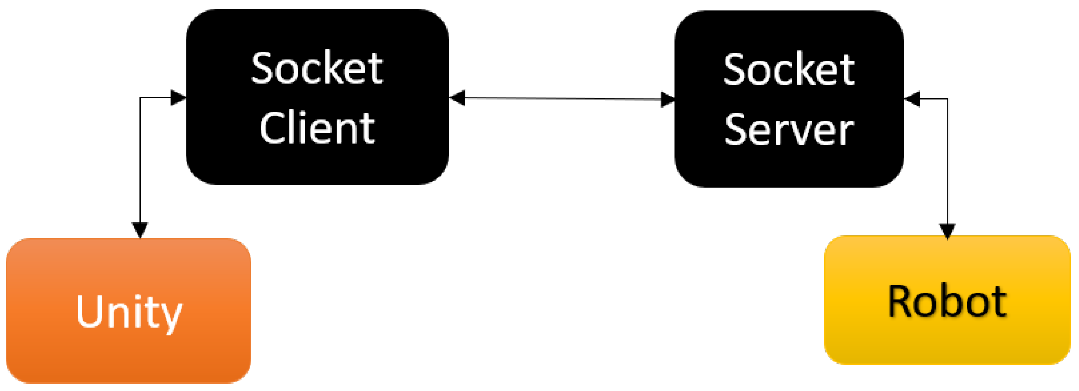
On the unity platform, the socket messaging client is written in C# script. Now, both physical and digital models are ready to communicate via socket channel. After a successful handshake between Unity and Robot Controller, as shown in Figure 8, required data can be exchanged between them.
Programming for Communication Setup: The programming part is designed considering the modularity of adding features to the robot both on the physical and digital sides. In this experimentation, the Unity scripts are divided into three parts:
- (1)
- Socket server client: Responsible for initiating a connection with socket server written on the robot side.
- (2)
- Reading and sending data: This script reads the robot joints data, which is generated by IK, and sends it to the robot over socket messaging port.
- (3)
- Data recording: If the Digital Twin is not connected to the PR, a provision is created to temporarily store the data inside the Unity environment in a text file format. In addition to this, work has also been done to save the data sent to the robot via socket client in PR memory for its repetitive operations.
3.2.8. Virtual Reality (VR) Interface
VR interface is present in the gaming industry for a long time. Currently, companies and researchers have been exploring the possibilities to utilize this technology in different sectors as well. The manufacturing industry is one of them, and they are exploring the benefits and use cases of VR interface. In this experimentation, we integrated VR with an industrial robot, with the scope of easing the programming and monitoring robotic actions. In the traditional approach, to program a robot for a specific task, we teach the intermediate points via teach pendant or by guiding a robot by holding its axes (also known as collaborative robots) and save these intermediate points inside robot memory. However, to successfully guide and generate an effective path requires training and experience for the operators.
Setting VR Environment in Unity: In contrast to the existing approach, the VR interface provides a simplified way of programming the desired trajectory. In this work, HTC Vive is used to interact with the robot. This interaction is facilitated using the robot’s digital model in a virtual environment that is created on a Unity platform.
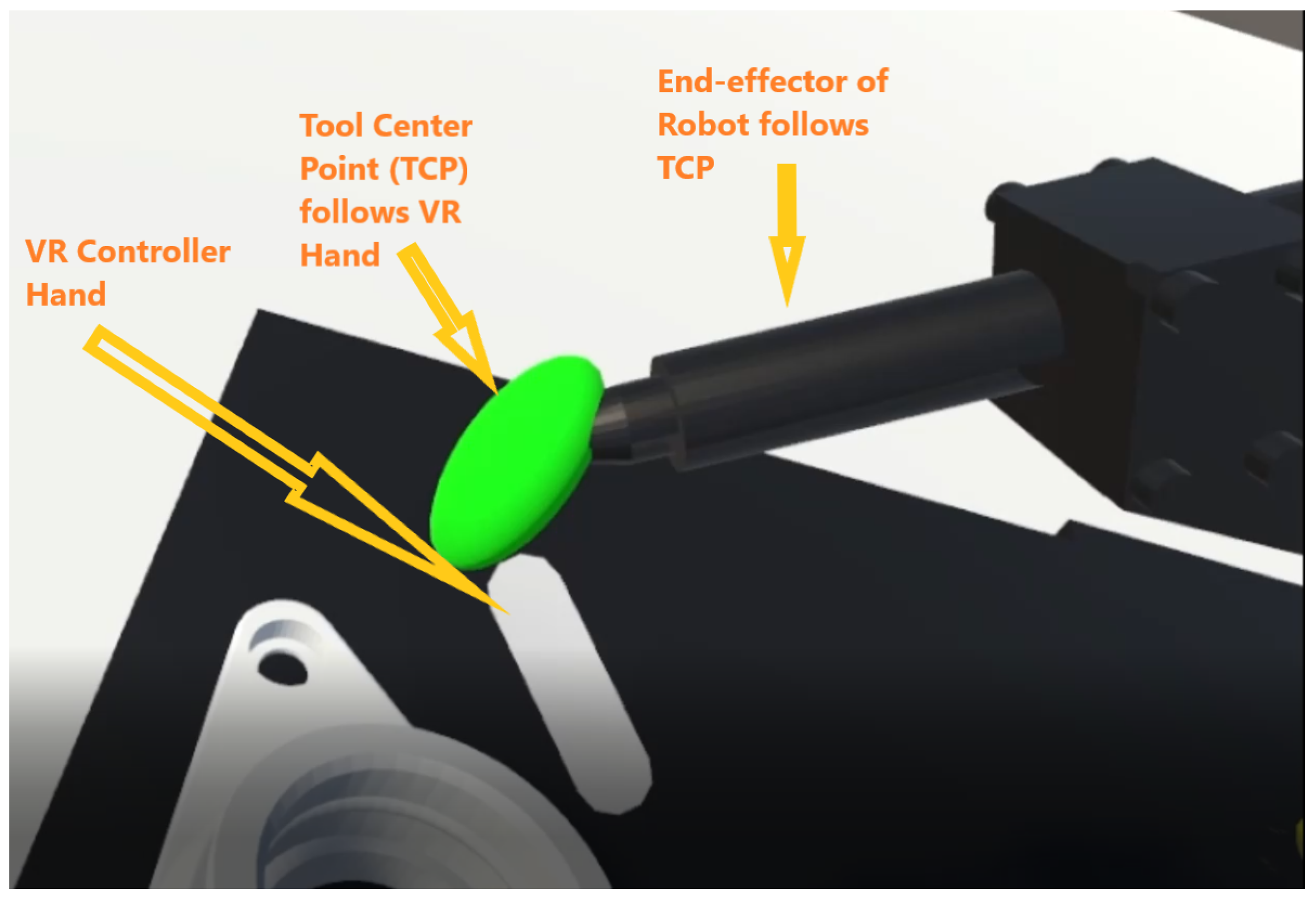
In a virtual environment, the VR controller generates a new position by holding the digital model’s TCP and guiding it around the component/region of interest. The updated position data is sent to an inverse kinematic algorithm, and the algorithm generates the corresponding joint angles for the robot joints to reach the updated position of TCP. By doing so, the tip of the end-effector follows the TCP and generates an entire program from the initial position to the complete trajectory. Figure 9 shows controlling of twin model in a virtual environment using VR controller.
4. Experimentation and Results
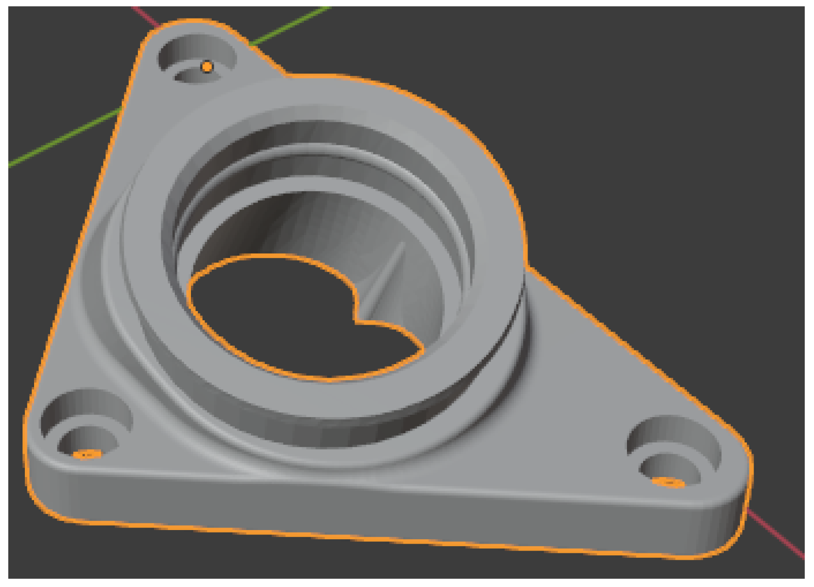
We experimented to analyze the responsiveness and feasibility of the twin model to generate a robot trajectory program for a PR. We consider the setup environment as shown in Figure 4. The component for which the trajectory is generated is highlighted in Figure 10.
By holding a VR controller in the digital environment, we traced the circular edge of the above component and generated a trajectory from the robot’s initial position to its final position. We studied various parameters that focus on the capability for real industrial applications, such as time delay, trajectory replication on the PR side.
4.1. Time Delay
First, we examined the time-lapse between the digital model and PR to exchange the data. As per the experiment’s setup, the time-lapse for transferring the joint angles (six joint angles in this experimentation) data of the digital model to the PR model was observed. We analyzed that using socket messaging takes approximately 40 ms (milliseconds) to transfer the joint data and read robot status signals in a digital setup. This is a considerable improvement compared to the 150 ms that was reported in previous research [41].
The process for calculating the time delay is explained step-by-step in Algorithm 1. Given the socket client object (S) that is connected to the Digital Twin socket server. Now, S is able to read robot joint data by using the READ command. The output of the algorithm is average latency (L). In steps 4–12, we are reading the robot joint data in between start_time and end_time, the moment a keyword “bye” is received by S, it understands that there is no more data, and it terminates the loop. In the end, the total time difference is divided by the number of values received, i.e., c, which gives us a total latency L or total time taken over a client-socket communication channel to receive robot joint angles for one trajectory.
| Algorithm 1: Time Delay Calculation |
 |
4.2. Joint Movement Analysis of Simulation Platforms (Digital Twin and Roboguide)
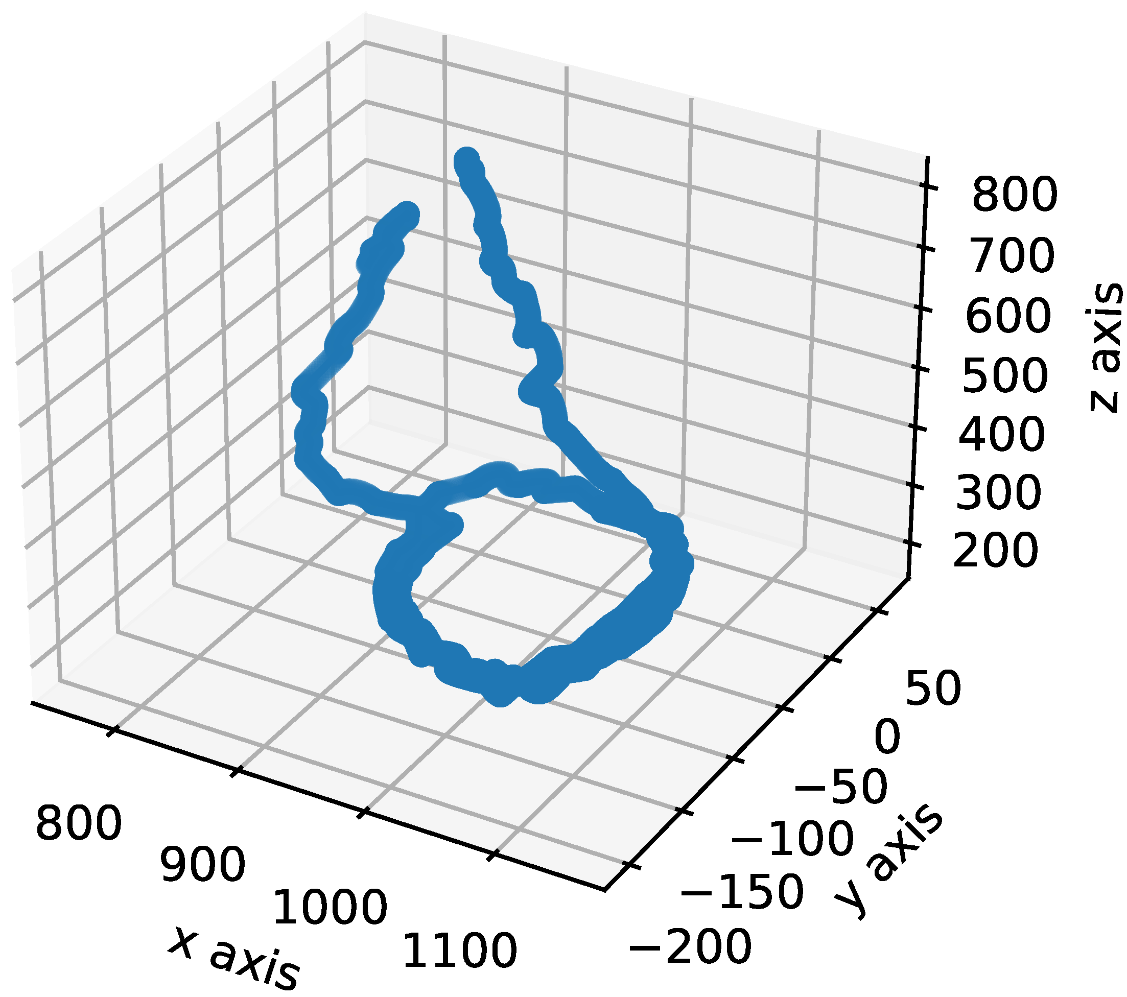
Now, let us dive into the accuracy of robot movement attained in a Digital Twin process. Figure 11 shows a trajectory path created via VR controller movement in the virtual environment. The path traced by the TCP of a robot is plotted in a 3D graph. Here the movement in 3D space is in mm (millimeters).
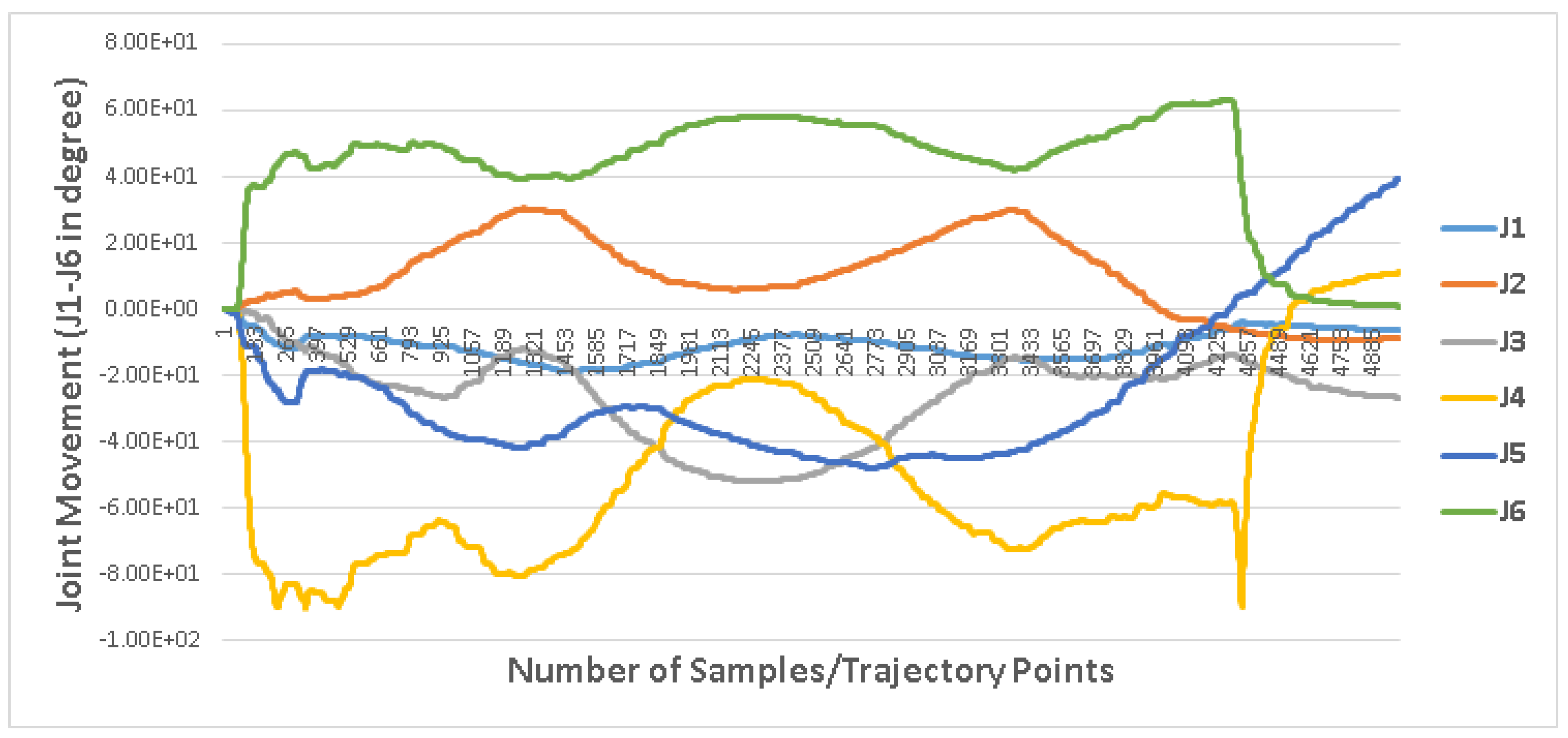
For the above trajectory, Figure 12, shows the range of movement of joints J1–J6 (in degree) of a robot arm to attain the intermediate points across the motion path. At every step, when the TCP position is updated, the IK algorithm generates a new set of Joint angles (J1–J6).
After looking into the trajectory and joint angle movement, let us compare the joint movement data of digital and PR, as we discussed earlier in Section 3.2.5 that on digital and PR model, we are using IK and forward kinematics (FK) algorithms. As a result, there is a possibility of some difference in the Commanded and Executed Joint movements.
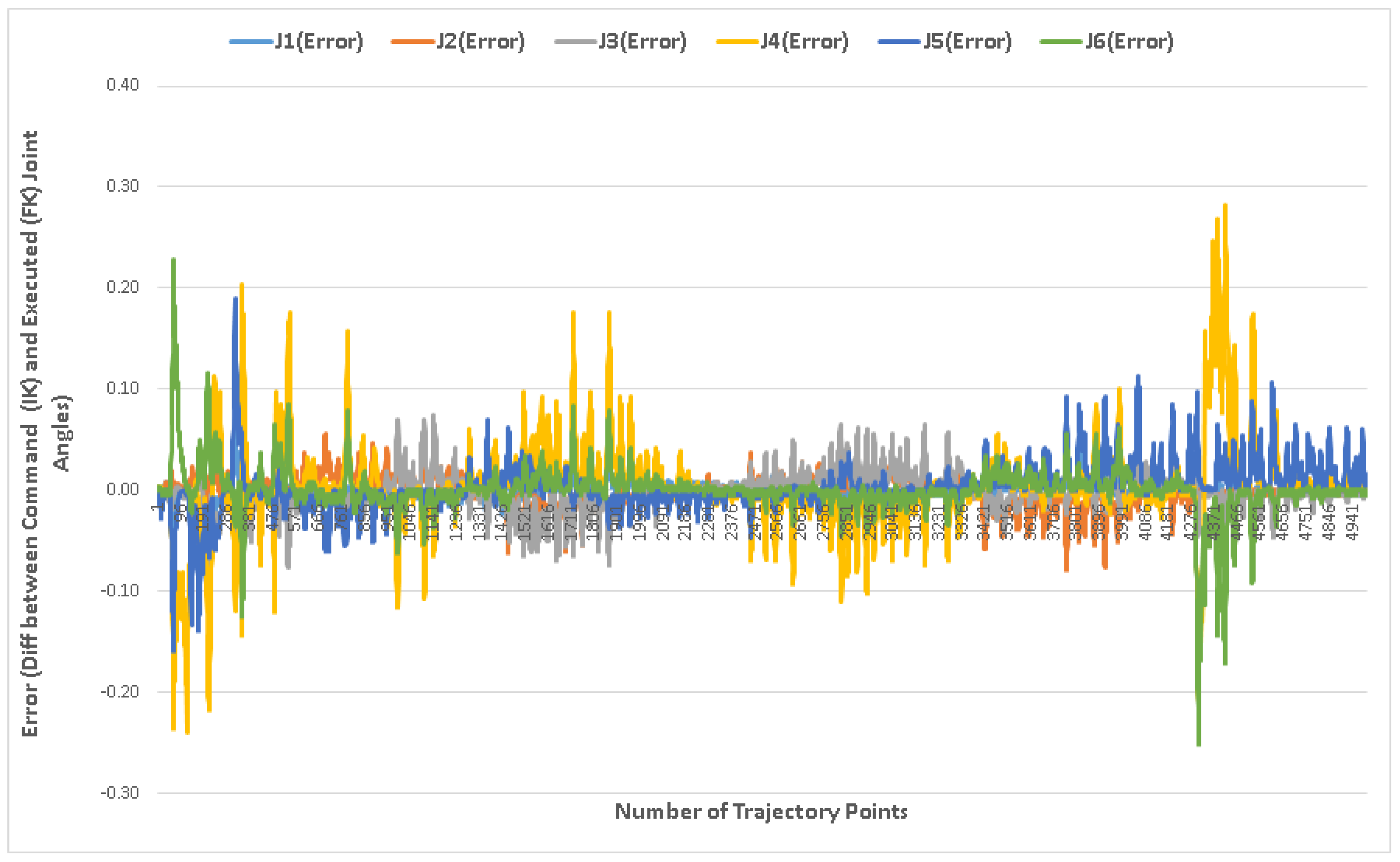
Figure 13 shows the difference between commanded joint angles, which is the data generated from the digital robot model and executed motion in a PR. It is observed that the value of error across each joint J1–J6 varies from 0.01 and 0.28 on the positive range of motion.
Table 3, shows the range of movement of robot joints for a specific component, component already shown in Figure 10. Columns 2 and 3 indicate the minimum and maximum value of joint movement in degree, and columns 4 and 5 show the range of errors recorded in PR, where the joint movement is executed with the FK algorithm. Similarly, we created a random trajectory and showed the range of motion and error values in columns 6 to 9. From Table 3, it can be observe that the range of error is between −0.28 to 0.28.
Therefore, we can infer that this error value is quite low (in respect of industrial robots). The error is at its peak at the start and end of a trajectory. There can be two different factors contributing to this error, (1) error can be due to acceleration and deceleration cycle across robot joints, and (2) can be induced by the conversion process of IK to FK.
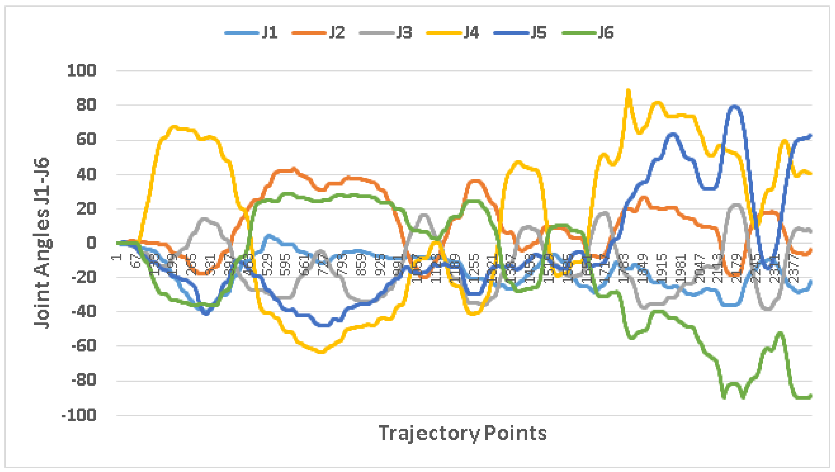
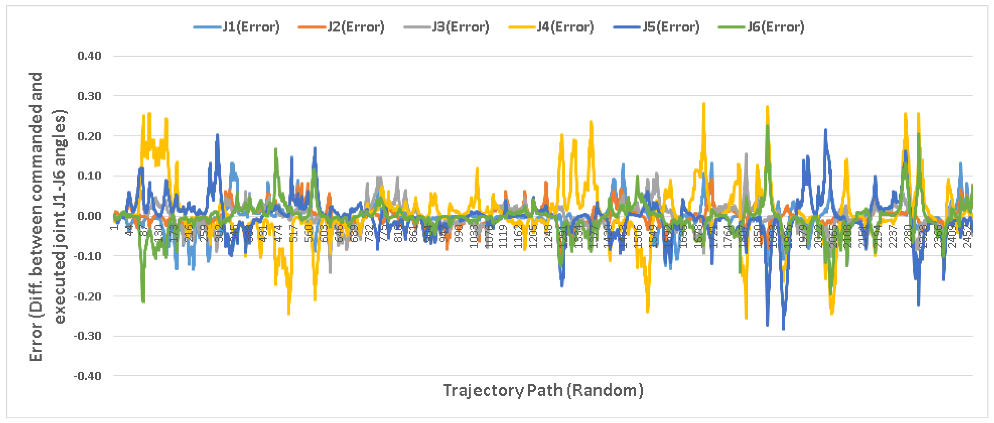
To analyze the cause of error, a random trajectory is generated in VR, and we analyzed the errors across the joints of the PR. Figure 14 shows the range of movement of a robot arm joint angles. The purpose of the random movement is to obtain more details on the error. Whether it increases with an increase in joint movement range or it depends on acceleration and deceleration cycle.
Figure 15, shows the same error range as compared to Figure 13, even during the random motion of TCP, the error range remains in the same window of 0.1 to 0.28.
From the above error plots, there is a possibility that the deviation of joint movements is due to acceleration or deceleration values. As the joint moves from 0 to 80, the error also increases. However, after attaining a particular value, the error gradually decreases if the movements remain in that range. In addition to this, it is observed that the error across the J4–J6 joint is more as compared to J1–J3 joints, as the movement across J4–J6 varies more abruptly in the range of 0–100 as compared to J1 to J3 movement pattern, which is smooth, and its range of motion is less (0–30) compared to other joints.
4.3. Joint Movement Analysis of Digital Twin and FANUC Robot
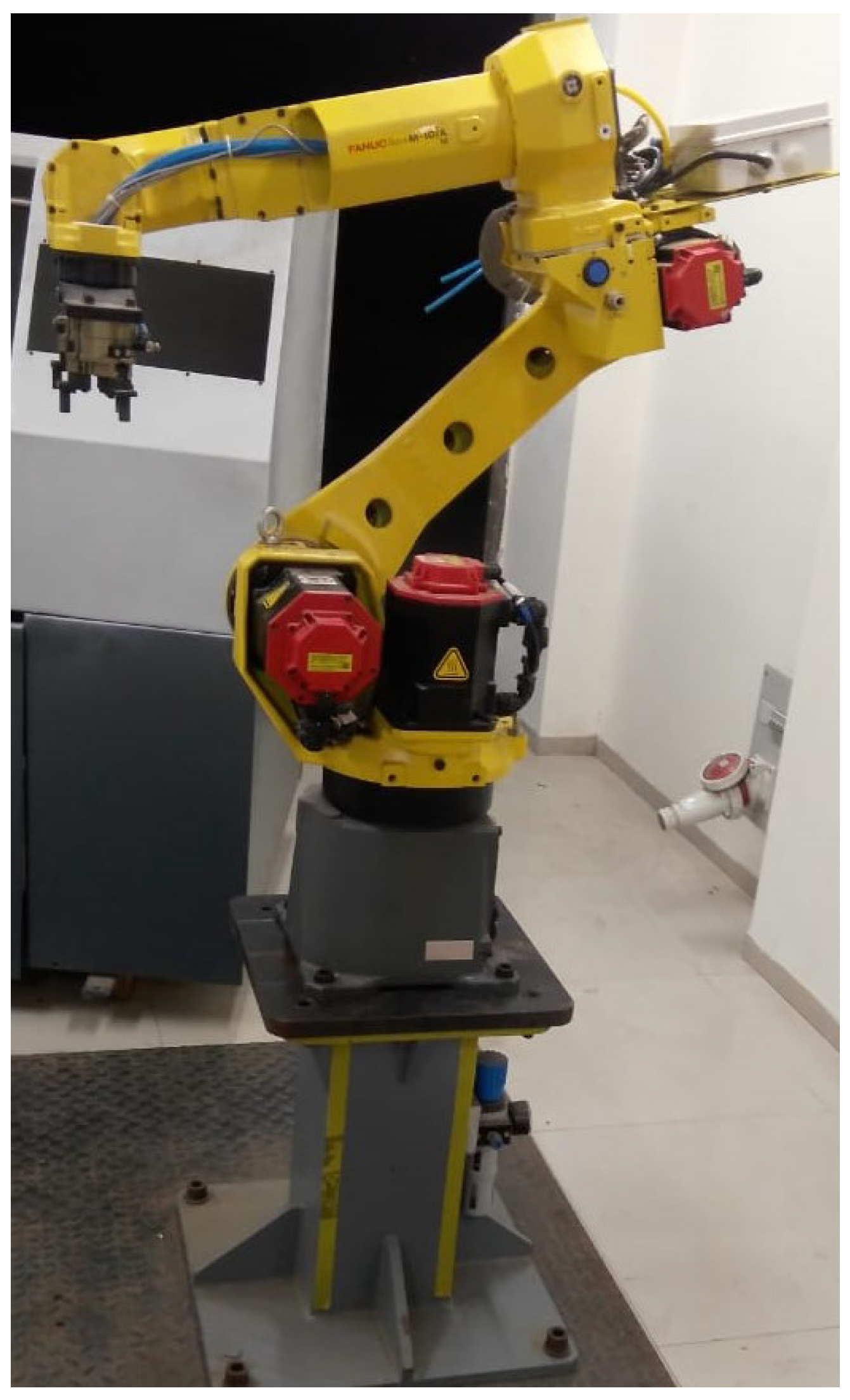
We used a real robot of FANUC (model M-10ia/12), as shown in Figure 16. Further, we tested another random trajectory generated by a digital platform and executed it on a real robot.
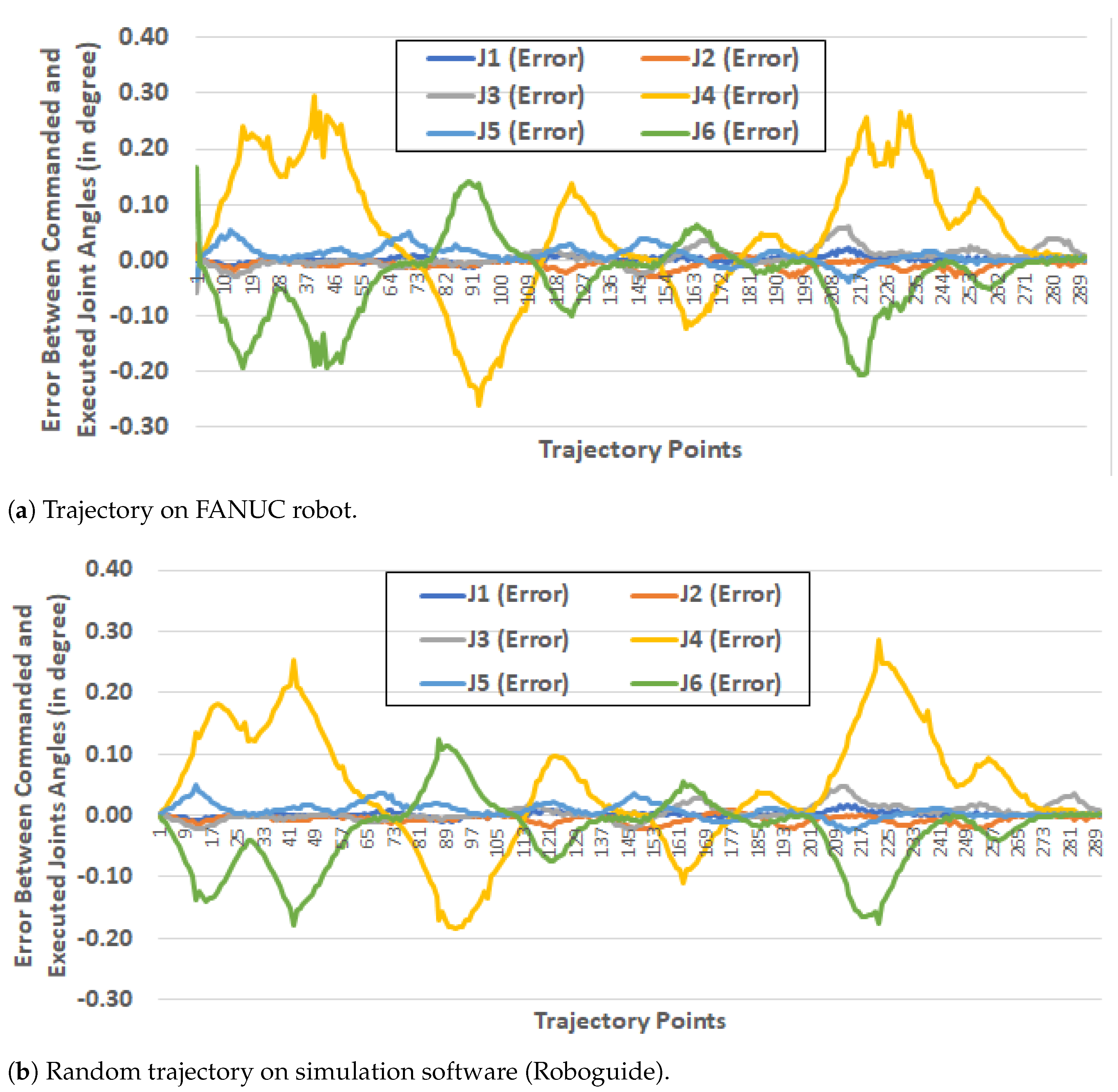
Figure 17, compares the error between joints angles of commanded data which is generated in Unity via VR movement and executed data on Roboguide and robot. In this paper, we referred to PR as a PR on Roboguide, which is a simulation software of FANUC. However, we further tested the program on the actual FANUC robot also. Figure 17a shows a random path execution on the FANUC robot, and Figure 17b shows roboguide simulation joint error. The joint error in both cases is almost the same, except the rising and falling edges are sharp in actual robot joint angle movement. Apart from slight deviation in joint angle errors, the range of error is slightly increased in the case of the actual robot. As Figure 17a shows, the error touches the value of 0.3, whereas the roboguide simulation shows the maximum value of 0.28.
5. Discussion
Here, we discuss the solution/framework developed in this work. The model prepared in this experimentation is a sustainable solution, in a way that it is independent of the robot model (see Section 5.1 for detail). Additionally, we showed some advantages of using VR interface for programming robot and how it can benefit in various challenging tasks using Used Case scenarios in Section 5.2.
5.1. Sustainable Solution for FANUC Robots
The software components under this experimentation are developed in such a way that we can generalize this implementation process for any FANUC robot. The generalization provides sustainability for programming a wide range of FANUC robots. This Digital Twin model removes the overhead of spending time to learn robot programming and obtaining technical details and can provide a friendly environment for even first-time users. To extend the solution developed in this paper, there are a few steps that need to be followed. The first step towards establishing Digital Twin is to develop a 3D animated compatible robot, which can be done by following the steps defined in Section 3.2.2 (Model Rigging).
After importing the 3D animated robot developed above, it can be imported in Unity, and other scripts that are developed in this work can be simply plugged into any digital and PR model. This provides a generalized solution for the entire range of FANUC robots. However, this solution has a limitation that it may not be compatible with other robotic manufacturer companies, such as KUKA, NACHI, ABB, YASKAWA, etc.
5.2. Use Case Scenarios
The concept of Digital Twin has applications in vast domains, such as Industry Planning, production estimation, medical division for remote surgery, robot trajectory simulation, etc. Here, we discussed a few applications that give a more specific idea about VR environment utilization and the benefits of Digital Twin two-way communication. These applications include trajectory programming for complex edges and space-constrained environments and generating synthetic data for machine learning applications for robotic programming, such as robot perception models.
5.2.1. Trajectory Planning for Complex Edges
Pointing/guiding a PR end-effector at a particular position and its orientation can be a difficult or time-consuming task via a manual programming method. One such setup is shown in Figure 18. The edges of the component that requires high accuracy take a lot of time and often lead to minor adjustments. This rework can be avoided by visualizing the component details in a VR environment, where we can clearly see the detailed 3D view of the region of interest and move the VR hand around it.
5.2.2. Program Creation in Space Constrained Surroundings
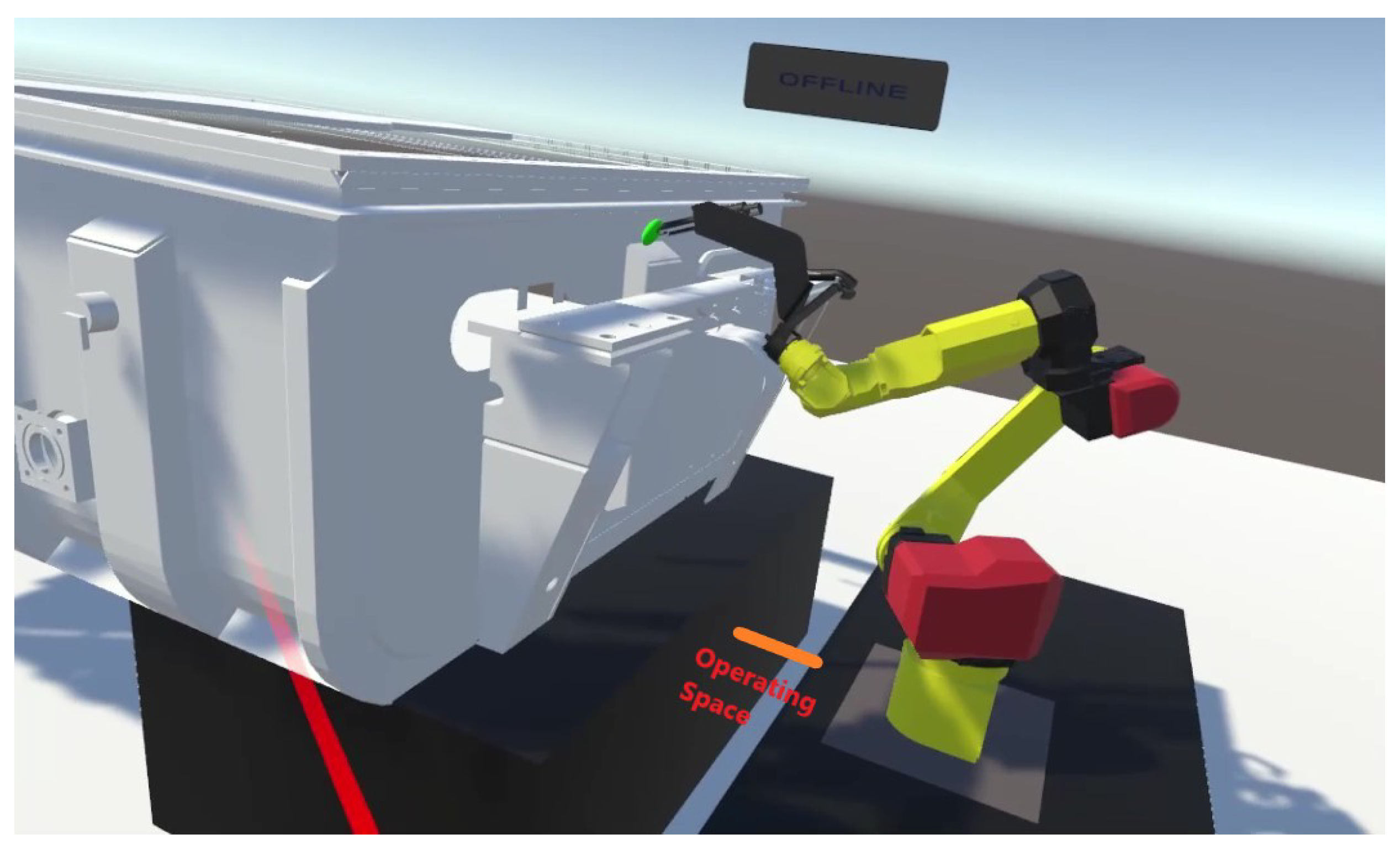
The space required or available for a new setup is always a challenge for factories and manufacturing units. This pushes the limits and demands a minimum space acquisition for setting up robotic/machine cells. Here, the capability of a virtual environment can be used to create a motion path in constrained spaces and simulate the feasibility of setting up a physical system.
Figure 19 shows a setup of a tank welding application. Here robot bench and component are closely placed. Such setup creates difficulties in creating or troubleshooting a robot’s motion path. However, performing this task in a virtual environment provide a safe and well-defined environment for human–robot interaction.
5.2.3. Training Robotic Operations via Machine Learning
Currently, as we are trying to deploy robots for a broad range of applications, such as warehouse operations, agriculture, kitchen work, etc., the main challenge for making applications with a robot is to teach it for a dynamic handling environment. The process of teaching a robot can be done by creating synthetic data using a VR setup. Let us consider agriculture applications. To operate robots in an open environment, we have to gather data for the robot vision system under different illumination intensities. This environment is easy to create in a gaming engine as compared to capturing data in a real scenario. Gathering data in real scenarios can be time-consuming and costly.
6. Conclusions
In this paper, we successfully created a Digital Twin model of an industrial robot. The developed digital model communicates with the PR using client–server architecture via socket messaging. By integrating VR in a digital environment, we tested robot trajectory programs. The trajectories that are created in a virtual environment are easy to follow in a PR. In addition to this, we analyzed the accuracy of the trajectories executed in the PR as well as in Roboguide simulation software in comparison to the data generated via a VR environment, which was developed in this experimentation.
Based on the developed Digital Twin model for industrial robots, our contribution towards research enhancement can be summarized as follows: (1) Online motion between the virtual environment and PR for desired trajectories, and a generalized program was created on the PR for repetitive motion execution. (2) Ease of programming for complex edges and space-constrained environments: Based on the survey, we can confidently conclude that the VR environment was easy to operate and highly interactive for robot programming as compared to other available programming tools. (3) Communication across different platforms (Dot Net and Karel) was established.
The simulation analysis showed the latency of approximately 40 ms (milliseconds) with an error range of −0.28 to 0.28 across the robot joint movements in a simulation environment and −0.3 to 0.3 across the actual robot joint movements. Therefore, with this latency and accuracy, we can utilize this model effectively for industrial applications. However, for high precision control, there is a need to smooth out the joint movements by implementing a smoothing function or other algorithms.
Limitations: There are a few limitations of this work as this work can only be copied/applied to FANUC robots. On the robot side, the scripts were developed in KAREL language, which is native to FANUC robots only. As per our knowledge, the KAREL platform is not being used by any other robot manufacturer company. However, this limitation can be removed with work to establish communication with other manufacturer robot libraries. Some of them provide Dot Net libraries or Java-based APIs to interact and establish communication and control joint movements.
Future Work: Gaming platforms are loaded with many features that can be extended to an industrial environment. One such example is the multiple user single-server virtual reality system. There are several networking games where players from different locations create their virtual avatars and interact in a simulated environment. The same concept can be implemented in the industrial environment via a game engine. The main advantage of this is a better understanding of the problem. For example, suppose there is a robot that is installed at a remote location, and you, as a service provider, must listen to and understand the customers and also help them to solve the problem.
Assisting over telephonic discussion takes a great deal of time to obtain a gist of the problem as a client is less likely to be comfortable with technical terms and may land on different understanding nodes. However, having a Digital Twin model eases the process of explaining and understanding the problem in a short span of time.
The accuracy of the trajectories generated via VR environment depends on human hand movement, and most of the motion path appears rough compared to the trajectories generated via simulation software. To overcome this, further work is required to smooth the trajectories. This will help in utilizing the complete potential of the Digital Twin in a broad range of application areas. At present, there is not much work that compares the motion path between Digital and Physical models. At present, most of the focus is on interaction system development with VR/Augmented Reality/MR.
Author Contributions
Conceptualization, methodology, validation, formal analysis, literature review, writing—original draft preparation, G.G.; writing—review and editing, funding acquisition, G.A. and V.K.; supervision, G.A. and V.K. All authors have read and agreed to the published version of the manuscript.
Funding
This research was supported by project AR16077 Smart Industry Centre (SmartIC) No. 2014-2020.4.01.16-0183, supported by the EU Regional Development Fund and by the Estonian Research Council under grant PSG453 “Digital twin for propulsion drive of an autonomous electric vehicle”.
Institutional Review Board Statement
Not Applicable.
Informed Consent Statement
Not Applicable.
Data Availability Statement
Not Applicable.
Conflicts of Interest
The authors declare no conflict of interest.
Abbreviations
The following abbreviations are used in this manuscript:
| CAD | Computer Aided Design |
| 3D | 3 dimensional |
| fbx | Filmbox 3D file format |
| FK | Forward Kinematics |
| HMD | Head Mounted Device |
| IK | Inverse Kinematics |
| KAREL | Programming Language based on PASCAL |
| KDTMC | Knowledege Driven Digital Twin Manufaturing Cell |
| MR | Mixed Reality |
| PR | Physical Robot |
| STL | Standard Triangular Language |
| TCP | Tool Center Point |
| VR | Virtual reality |
References
- Cordes, M.; Hintze, W. Offline simulation of path deviation due to joint compliance and hysteresis for robot machining. Int. J. Adv. Manuf. Technol. 2017, 90, 1075–1083. [Google Scholar] [CrossRef]
- Olabi, A.; Damak, M.; Bearee, R.; Gibaru, O.; Leleu, S. Improving the accuracy of industrial robots by offline compensation of joints errors. In Proceedings of the 2012 IEEE International Conference on Industrial Technology, Athens, Greece, 19–21 March 2012; pp. 492–497. [Google Scholar]
- Kuts, V.; Modoni, G.E.; Otto, T.; Sacco, M.; Tähemaa, T.; Bondarenko, Y.; Wang, R. Synchronizing physical factory and its digital twin through an IIoT middleware: A case study. Proc. Est. Acad. Sci. 2019, 68, 364–370. [Google Scholar] [CrossRef]
- Design Presentation Associates, Inc. CAD File Formats. Available online: https://www.designpresentation.com/blog/cad-file-formats/ (accessed on 1 July 2021).
- Eberly, D. 3D Game Engine Design: A Practical Approach to Real-Time Computer Graphics; CRC Press: Boca Raton, FL, USA, 2006. [Google Scholar]
- Burghardt, A.; Szybicki, D.; Gierlak, P.; Kurc, K.; Pietruś, P.; Cygan, R. Programming of industrial robots using virtual reality and digital twins. Appl. Sci. 2020, 10, 486. [Google Scholar] [CrossRef] [Green Version]
- Hart, J.W.; DePalma, N.; Pryor, M.W.; Hayes, B.; Kruusamäe, K.; Mirsky, R.; Xiao, X. Exploring Applications for Autonomous Nonverbal Human-Robot Interaction. In Proceedings of the Companion of the 2021 ACM/IEEE International Conference on Human-Robot Interaction, Boulder, CO, USA, 8–11 March 2021; pp. 728–729. [Google Scholar]
- Muszyńska, M.; Szybicki, D.; Gierlak, P.; Kurc, K.; Burghardt, A.; Uliasz, M. Application of Virtual Reality in the Training of Operators and Servicing of Robotic Stations. In Proceedings of the PRO-VE 2019: Collaborative Networks and Digital Transformation, Turin, Italy, 23–25 September 2019; Springer: Cham, Switzerland, 2019; pp. 594–603. [Google Scholar]
- Kuts, V.; Otto, T.; Tähemaa, T.; Bondarenko, Y. Digital twin based synchronised control and simulation of the industrial robotic cell using virtual reality. J. Mach. Eng. 2019, 19, 128–145. [Google Scholar] [CrossRef] [Green Version]
- Malik, A.A.; Bilberg, A. Digital twins of human robot collaboration in a production setting. Procedia Manuf. 2018, 17, 278–285. [Google Scholar] [CrossRef]
- Kamińska, D.; Sapiński, T.; Wiak, S.; Tikk, T.; Haamer, R.E.; Avots, E.; Helmi, A.; Ozcinar, C.; Anbarjafari, G. Virtual reality and its applications in education: Survey. Information 2019, 10, 318. [Google Scholar] [CrossRef] [Green Version]
- Kamińska, D.; Smółka, K.; Zwoliński, G.; Wiak, S.; Merecz-Kot, D.; Anbarjafari, G. Stress reduction using bilateral stimulation in virtual reality. IEEE Access 2020, 8, 200351–200366. [Google Scholar] [CrossRef]
- Kamińska, D.; Zwoliński, G.; Wiak, S.; Petkovska, L.; Cvetkovski, G.; Di Barba, P.; Mognaschi, M.E.; Haamer, R.E.; Anbarjafari, G. Virtual Reality-Based Training: Case Study in Mechatronics. Technol. Knowl. Learn. 2020, 1–17. [Google Scholar] [CrossRef]
- Zhang, H.; Ma, L.; Sun, J.; Lin, H.; Thürer, M. Digital twin in services and industrial product service systems: Review and analysis. Procedia CIRP 2019, 83, 57–60. [Google Scholar] [CrossRef]
- Tao, F.; Cheng, J.; Qi, Q.; Zhang, M.; Zhang, H.; Sui, F. Digital twin-driven product design, manufacturing and service with big data. Int. J. Adv. Manuf. Technol. 2018, 94, 3563–3576. [Google Scholar] [CrossRef]
- Lu, Y.; Liu, C.; Kevin, I.; Wang, K.; Huang, H.; Xu, X. Digital Twin-driven smart manufacturing: Connotation, reference model, applications and research issues. Robot. Comput.-Integr. Manuf. 2020, 61, 101837. [Google Scholar] [CrossRef]
- Liu, J.; Du, X.; Zhou, H.; Liu, X.; Ei Li, L.; Feng, F. A digital twin-based approach for dynamic clamping and positioning of the flexible tooling system. Procedia CIRP 2019, 80, 746–749. [Google Scholar] [CrossRef]
- Petkovska, L.; Cvetkovski, G.; Kaminska, D.; Wiak, S.; Firych-Nowacka, A.; Lefik, M.; Sapinski, T.; Zwolinski, G.; Di Barba, P.; Mognaschi, M.E.; et al. ViMeLa PROJECT: An Innovative Concept for Teaching Students in Mechatronics Using Virtual Reality. In Proceedings of the 7th Symposium On Applied Electromagnetics (SAEM’18), Podcetrtek, Slovenia, 17–20 June 2018; pp. 17–20. [Google Scholar]
- Oleksy, M.; Budzik, G.; Sanocka-Zajdel, A.; Paszkiewicz, A.; Bolanowski, M.; Oliwa, R.; Mazur, Ł. Industry 4.0 Part I. Selected applications in processing of polymer materials. Polimery 2018, 63, 531–535. [Google Scholar] [CrossRef]
- Zhang, C.; Zhou, G.; He, J.; Li, Z.; Cheng, W. A data-and knowledge-driven framework for digital twin manufacturing cell. Procedia CIRP 2019, 83, 345–350. [Google Scholar] [CrossRef]
- Ostanin, M.; Klimchik, A. Interactive robot programing using mixed reality. IFAC-PapersOnLine 2018, 51, 50–55. [Google Scholar] [CrossRef]
- Manou, E.; Vosniakos, G.C.; Matsas, E. Off-line programming of an industrial robot in a virtual reality environment. Int. J. Interact. Des. Manuf. (IJIDeM) 2019, 13, 507–519. [Google Scholar] [CrossRef]
- Pérez, L.; Diez, E.; Usamentiaga, R.; García, D.F. Industrial robot control and operator training using virtual reality interfaces. Comput. Ind. 2019, 109, 114–120. [Google Scholar] [CrossRef]
- Pérez, L.; Rodríguez-Jiménez, S.; Rodríguez, N.; Usamentiaga, R.; Garcia, D.F. Digital Twin and Virtual Reality Based Methodology for Multi-Robot Manufacturing Cell Commissioning. Appl. Sci. 2020, 10, 3633. [Google Scholar] [CrossRef]
- Frank, A.G.; Dalenogare, L.S.; Ayala, N.F. Industry 4.0 technologies: Implementation patterns in manufacturing companies. Int. J. Prod. Econ. 2019, 210, 15–26. [Google Scholar] [CrossRef]
- Castelo-Branco, I.; Cruz-Jesus, F.; Oliveira, T. Assessing Industry 4.0 readiness in manufacturing: Evidence for the European Union. Comput. Ind. 2019, 107, 22–32. [Google Scholar] [CrossRef]
- Zhou, G.; Zhang, C.; Li, Z.; Ding, K.; Wang, C. Knowledge-driven digital twin manufacturing cell towards intelligent manufacturing. Int. J. Prod. Res. 2020, 58, 1034–1051. [Google Scholar] [CrossRef]
- Wu, C.; Zhou, Y.; Pessôa, M.V.P.; Peng, Q.; Tan, R. Conceptual digital twin modeling based on an integrated five-dimensional framework and TRIZ function model. J. Manuf. Syst. 2021, 58, 79–93. [Google Scholar] [CrossRef]
- Aheleroff, S.; Xu, X.; Zhong, R.Y.; Lu, Y. Digital twin as a service (DTaaS) in industry 4.0: An architecture reference model. Adv. Eng. Inform. 2021, 47, 101225. [Google Scholar] [CrossRef]
- Sepasgozar, S.M. Differentiating digital twin from digital shadow: Elucidating a paradigm shift to expedite a smart, sustainable built environment. Buildings 2021, 11, 151. [Google Scholar] [CrossRef]
- Team, R. FANUC Robot Specifications. 2017. Available online: https://www.robots.com/robots/fanuc-m-10ia-12 (accessed on 1 July 2021).
- Team, H.V. HTC VIVE Specification Specifications. Available online: https://www.vive.com/eu/product/vive/#vive-spec (accessed on 1 July 2021).
- HTC VIVE Review. Available online: http://doc-ok.org/?p=1478 (accessed on 1 July 2021).
- Wasilenko, L. Getting Started with SteamVR and Unity. 2019. Available online: https://www.taylorfrancis.com/chapters/edit/10.1201/b21598-3/getting-started-steamvr-unity-lee-wasilenko (accessed on 1 July 2021).
- Jafari, A.; Tsagarakis, N.G.; Caldwell, D.G. AwAS-II: A new actuator with adjustable stiffness based on the novel principle of adaptable pivot point and variable lever ratio. In Proceedings of the 2011 IEEE International Conference on Robotics and Automation, Shanghai, China, 9–13 March 2011; pp. 4638–4643. [Google Scholar]
- Abtahi, M.; Pendar, H.; Alasty, A.; Vossoughi, G.R. Calibration of parallel kinematic machine tools using mobility constraint on the tool center point. Int. J. Adv. Manuf. Technol. 2009, 45, 531. [Google Scholar] [CrossRef]
- Blanton, M.; Stephens, A.; Knuth, E.; Gardiner, A.M.; Isler, I.; Kim, J.S. The development of children’s algebraic thinking: The impact of a comprehensive early algebra intervention in third grade. J. Res. Math. Educ. 2015, 46, 39–87. [Google Scholar] [CrossRef]
- Horn, R.A.; Johnson, C.R. Matrix Analysis; Cambridge University Press: Cambridge, UK, 2012. [Google Scholar]
- Davis, C. The norm of the Schur product operation. Numer. Math. 1962, 4, 343–344. [Google Scholar] [CrossRef]
- Pattis, R.; Roberts, J.; Stehlik, M. Karel the Robot. A Gentele Introduction to the Art of Programming; John Wiley & Sons: Hoboken, NJ, USA, 1981. [Google Scholar]
- Laaki, H.; Miche, Y.; Tammi, K. Prototyping a digital twin for real time remote control over mobile networks: Application of remote surgery. IEEE Access 2019, 7, 20325–20336. [Google Scholar] [CrossRef]
Figure 1.
Control cycle between a Digital and Physical model. This figure is divided into six steps, step (1) shows a Twin model of robot in a gaming engine, (2) VR device interface, (3) Inverse Kinematics algorithm (BioIK), (4) Data Communication between a Digital robot and PR over socket messaging, (5) Actual Robot, and (6) Forward Kinematics algorithm that runs on the robot.

Figure 2.
3D model in Blender software.

Figure 3.
Defining Pivot Points across the links of a robot arm.

Figure 4.
Robot setup and the environment.

Figure 5.
Tool center point.

Figure 6.
BioIK parameters.

Figure 7.
Coordinates system.

Figure 8.
Communication channel setup between the Physical and Digital robot.

Figure 9.
Controlling the twin model via virtual reality controller.

Figure 10.
Trajectory component.

Figure 11.
Robot trajectory (axis values in mm).

Figure 12.
Range of movement of individual joints.

Figure 13.
Difference between the Commanded (IK) and Executed (FK) joint angles.

Figure 14.
Joint angle movement for a random trajectory.

Figure 15.
Difference between Commanded (IK) and Executed (FK) joint angles.

Figure 16.
Real robot M-10ia/12 (FANUC).

Figure 17.
Trajectory comparison between FANUC Robot and FANUC simulation software (Roboguide).

Figure 18.
VR Environment for programming an engine component.

Figure 19.
Robotic operation in constrained space.


Table 1.
FANUC Robot M-10iA/12 Specifications [31].
Table 1.
FANUC Robot M-10iA/12 Specifications [31].
| Robot Specifications | Motion Speed | Motion Range |
|---|---|---|
| Axes: 6 | J1: 230/s (4.01 rad/s) | J1: +340 −360 |
| Payload: 12 kg | J2: 225/s (3.93 rad/s) | J2: ±250 |
| H-Reach: 1420 mm | J3: 230/s (4.01 rad/s) | J3: ±447 |
| Repeatability: ±0.8 mm | J4: 430/s (7.5 rad/s) | J4: ±380 |
| Robot Mass: 130 kg | J5: 430/s (7.5 rad/s) | J5: ±380 |
| Structure: Articulated | J6: 230/s (11 rad/s) | J6: ±720 |
| Mounting: Floor, Inverted, Angle |
Table 2.
HTC Vive specifications of the headset along with cntrollers.
| Display refresh rate | 90 Hz |
| Resolution each eye | |
| Field of View (FOV) | 110 |
| HMD refresh rate | 225 Hz |
| Controller Pose refresh rate | 250 Hz |
Table 3.
The joint movement for specific and random trajectory, movement range, and error range shows the minimum and maximum values in degrees.
Table 3.
The joint movement for specific and random trajectory, movement range, and error range shows the minimum and maximum values in degrees.
| Component Trajectory | Random Trajectory | |||||||
|---|---|---|---|---|---|---|---|---|
| Movement Range | Error Range | Movement Range | Error Range | |||||
| Min | Max | Min | Max | Min | Max | Min | Max | |
| J1 | −18.800 | 0.100 | −0.138 | 0.077 | −4.220 | 39.800 | −0.131 | 0.148 |
| J2 | −9.300 | 30.300 | −0.092 | 0.077 | −43.200 | 19.900 | −0.112 | 0.125 |
| J3 | −51.900 | 0.000 | −0.092 | 0.077 | −38.400 | 22.200 | −0.139 | 0.155 |
| J4 | −89.900 | 11.100 | −0.232 | 0.277 | −89.400 | 63.600 | −0.255 | 0.282 |
| J5 | −47.900 | 39.500 | −0.185 | 0.155 | −48.200 | 79.400 | −0.282 | 0.216 |
| J6 | −0.100 | 62.900 | −0.270 | 0.232 | −28.6 | 90 | −0.212 | 0.226 |
Publisher’s Note: MDPI stays neutral with regard to jurisdictional claims in published maps and institutional affiliations. |
© 2021 by the authors. Licensee MDPI, Basel, Switzerland. This article is an open access article distributed under the terms and conditions of the Creative Commons Attribution (CC BY) license (https://creativecommons.org/licenses/by/4.0/).
Share and Cite
MDPI and ACS Style
Garg, G.; Kuts, V.; Anbarjafari, G. Digital Twin for FANUC Robots: Industrial Robot Programming and Simulation Using Virtual Reality. Sustainability 2021, 13, 10336. https://doi.org/10.3390/su131810336
AMA Style
Garg G, Kuts V, Anbarjafari G. Digital Twin for FANUC Robots: Industrial Robot Programming and Simulation Using Virtual Reality. Sustainability. 2021; 13(18):10336. https://doi.org/10.3390/su131810336
Chicago/Turabian StyleGarg, Gaurav, Vladimir Kuts, and Gholamreza Anbarjafari. 2021. "Digital Twin for FANUC Robots: Industrial Robot Programming and Simulation Using Virtual Reality" Sustainability 13, no. 18: 10336. https://doi.org/10.3390/su131810336
Note that from the first issue of 2016, this journal uses article numbers instead of page numbers. See further details here.