
Evaluation and Planning Decision on Façade Greening Made Easy—Integration in BIM and Implementation of an Automated Design Process


Research Unit of Ecological Building Technologies, Institute of Material Technology, Building Physics and Building Ecology, Faculty of Civil Engineering, Vienna University of Technology, A-1040 Vienna, Austria
*
Author to whom correspondence should be addressed.
Sustainability 2021, 13(16), 9387; https://doi.org/10.3390/su13169387
Submission received: 19 July 2021
/
Revised: 16 August 2021
/
Accepted: 19 August 2021
/
Published: 21 August 2021
(This article belongs to the Special Issue Building-Integrated Vegetation Systems for Sustainable Cities)
Abstract
:Façade greening at the intersection between buildings and urban space offers an optimal opportunity to integrate greenery into increasingly dense cities and influence the microclimate and contribute to high quality of life in urban areas. Despite proven numerous positive effects, there is still a lack of implementation and practical relevance is low until now. To integrate existing greening systems directly into future planning processes and thus keep up with the advancing digitalization in the building sector, an integration of these systems into Building Information Modeling (BIM) is urgently needed and in connection to this, the implementation of an automated planning process to support easier realization of greening projects contributing to a sustainable urban development. Therefore, BIM objects were created for five façade greening systems after analyzing the necessary basic data. Subsequently, an automated process was used to optimize the time-consuming conventional planning process of façade greening, with the aim of evaluating the simulated greening variants based on defined parameters. A case study presents the application of the prototypes and the possible calculations over the life cycle of the building. This development holds great potential by simplifying the process of decision-making and placing façade greenery on buildings.
1. Introduction
In order to provide sufficient living space in urban areas in the future, even as the number of inhabitants in cities continues to rise, more and more inner-city green spaces must give way. However, these areas have a decisive influence on the micro climate and thus the thermal comfort in cities and their associated recreational function affects the quality of city life [1,2,3,4,5,6]. Vertical greening of buildings offers the possibility for green spaces in the city in places where there seemed to be no room for them before [7]. In the following, in relation to this development, the state of the art is presented to describe the current situation, followed by the definition of the problem and by the formulation of the research questions investigated in this article.
1.1. State of the Art
The advantages of innovative façade greening systems are manifold and have been proven in numerous studies internationally. They range from positive effects on building physics and air quality over an aesthetic enhancement and finally to a positive influence on human health and well-being. Concerning the thermal performance, it can be stated that green walls improve the U-value in winter time in comparison to a non-insulated wall [8] and by this, reduce heat loss in winter [9]. For summer time, several investigations show that vertical greening systems are a valuable measure to reduce heat gain through external walls [10,11,12], reduce the surface temperature of the wall in comparison to a bare wall [13,14] and thus save cooling energy [15]. They as well improve thermal comfort [16], [17] and influence the microclimate in a positive way [13,18] and through this, attenuate the urban heat island effect [5,10,19,20]. In addition to these energetic effects due to evapotranspiration, shading and insulation [21], parameters such as noise are also affected trough the increased surface of the building envelope [22,23,24,25,26]. Another positive benefit of green façades is their influence on air pollutants, such as the binding of particulate matter [27,28]. In addition to these benefits, which can be quantified with technical measuring devices, positive effects on human health and well-being have also been qualitatively demonstrated through surveys [29]. In terms of the design of buildings and the urban environment, vertical greenery is particularly characterized by the advantage that it does not occupy valuable space on the ground [16].
Despite the proven numerous positive effects of vertical greening, especially in urban areas, its implementation has so far remained rather sporadic. On the one hand, this is due to the costs of installation, green care and technical maintenance, but also attributable to the lack of information and opportunities for planners, architects and decision makers to efficiently integrate vertical greening into the decision-making and planning process with little effort. Once the decision to design a building greenery has been made, the process of determining the greening system and selecting the plants begins. This decision is based on design and construction criteria. Criteria concerning the habitat of the plants (e.g., plant requirements, wind attack, light conditions), supply criteria (e.g., water and nutrient supply system, maintenance infrastructure, disposal, etc.) and construction criteria (e.g., building environment, statics, fixation, etc.) are considered. The design options depend on the urban space, the building and the plant. As the “living building material” plant is subject to special requirements in contrast to purely technical systems, the plant choice always requires the consultation of a specialist. The ecological and economical aspects in the surrounding of the building are important, as well as the integration into an already existing greening concept. Regarding the building, form and function must be considered. Except for climatic conditions, which can limit the height of the façade, there are no limits to the size of green areas as long as all the usual building law requirements are taken into account (e.g., fire protection, building physics, etc.). The targeted use of greenery on a façade can highlight the different functions of a building: rhythm, modularity and scale of buildings can be manipulated. In addition, the different geometric elements of a façade can contrast remarkably with the greenery and thus make the building stand out from the rest [30,31]. Research projects as well as findings from practice show that an early integration of greening into the planning process is necessary in order to also coordinate other aspects in the building and to enable green care and technical maintenance accordingly, thus enhancing a “design for maintainability” [32,33,34]. To ensure that vertical greening systems remain attractive in long term, the expertise and know-how of all disciplines involved must be bundled and made available for application. However, components and calculation possibilities for the integration of greening systems into the digital, architectural planning process are not available until now [35].
The majority of vertical greening projects installed to date are showpieces with the aim of creating an outstanding installation with a positive image. Justified by the increasing demand for climate resilience of cities and by the manifold positive effects of green infrastructure in urban spaces, the demand for vertical greening is increasing [36,37]. Based on this, it can be assumed that more and more cities are stipulating greening of buildings to a certain extent, for example, in the zoning plans—including the city of Vienna, where the new construction regulations stipulate greening of 20% of the façade area [38].
Previous approaches to analyzing the cost-benefit ratio of façade greening clearly show that a pure consideration of private costs and benefits is not sufficient to reflect the actual value of greening, since the effects of greening are complex and impact on different levels and affect different groups of people and areas. Therefore, other criteria need to be considered in future assessments in order to make statements about the actual profitability in a broader sense [39,40,41,42,43].
Approaches to classify greening systems have so far provided for a subdivision by the location of the plants as well as different types of construction, but an international standardization of designations has not yet been achieved [44,45]. In general, a distinction can be made between façade- and ground-based greening. While the ground-based greenery starts directly from the ground with climbing plants that grow, supported by climbing aids or without, up the building to their growth limit, the entire habitat of the plants in the façade-based system is located on the façade in provided troughs or cassettes. Accordingly, these systems consist of numerous individual components made of different materials and correspondingly different lifetimes. The aluminum troughs of the trough system, for example, have an intended service life of 40 years. The installed drip hoses of the irrigation system, on the other hand, only last ten years, according to the product data sheet. These properties, therefore, have an impact on the maintenance and technical servicing of the systems [46,47,48].
As an interdisciplinary working method, Building Information Modelling (BIM) offers a high level of planning quality for construction projects in terms of schedule and cost reliability, as well as increasing effectiveness in the management, visualization and exchange of construction-related data throughout the entire life cycle of the building [49,50]. Larger companies are already using BIM in different phases of the design and construction process and see potential for further development of digitization in the construction industry. However, the full potential of a digital twin of the building is not yet being exploited [50,51]. Moreover, the connection to visual programming has so far only been used to a limited extent in the construction industry, but offers great potential [52]. The file standard Industry Foundation Classes (IFC) is used to ensure the smoothest possible process and exchange between the various parties involved, so that openBIM can be used in a software-neutral manner. In addition, it is necessary to enable a standardized exchange of information based on a clear description and naming of the components. In Austria, this standardization of the parameter structure for the exchange of data is based on the freeBIM “attribute server”, which is considered in ÖNORM A-6241-2 [53]. Another area of this platform is the “component server”, from which manufacturer-specific components can be downloaded. If these BIM objects are used in planning, it is possible, among other things, to update these changes in the BIM model directly as soon as information from the manufacturers changes [54].
The use of BIM has already been intensively investigated in practice and in scientific studies with the aim of promoting the sustainable development of cities and making them “low carbon, energy efficient and environmentally friendly” [55]. Numerous publications deal with one of the interfaces between BIM, lean and sustainability with the overall result that a combined consideration of these aspects is more effective than a separate optimization [56]. In regard to low carbon buildings, Chen et al. [57] present a decision support model based on multiple criteria to provide a tool for the optimized selection of measures. Olawumi et al. [58] found as a result of a survey regarding the integration of sustainability aspects in BIM among experts in the construction industry that the enhanced project quality, the simulation of building performances as well as energy use and the possibilities to simplify the design process by multi-design alternatives are among the three most important benefits. A particular focus of these sustainable design strategies is the integration of green building assessments and life cycle assessments in BIM across all stages of the design and planning process [59,60,61,62] and the application of various certificates such as LEED and BREEAM for these calculations [63,64,65].
In previous studies, the application of BIM for an optimized and at least partly automated planning process in various areas of the construction sector has also been investigated and developed on a scientific basis. Liu et al. [66] developed rule-based design algorithms for lightframe residential buildings with the aim of automatic generation of design and planning alternatives while minimizing material waste. Other investigations deal with BIM-enabled design and planning of roof sheathing installation with the aim of reducing material waste through the demonstration of their effectiveness and feasibility exercising two case studies [67]. Sheikhkhoshkar et al. [68] research the possibilities of automated planning in the sector of structural engineering for concrete joint positioning with the result of a cost-effective and accurate methodology in BIM. Addressing the interface of architecture and agriculture, Khan at el. [69] present their developments to integrate urban agriculture in form of building integrated agriculture into BIM considering requirements of the plants, e.g., temperature and nutrients.
The integration of decision support in the construction industry has been found to be beneficial in early design phases, and the costs of the compared measures are always used in one of the decision-making steps [70,71,72,73,74]. In relation to building greening, Mahdiyar et al. [75] investigated the decision process for green roofs and developed a prototype decision support considering criteria such as water management, payback period and maintenance costs, structural consideration and energy savings.
1.2. Problem Statement and Research Questions
For façade greening, no such investigations and developments regarding BIM and decision support have been conducted so far, but they represent an indispensable step for its integration into the planning and design processes of the future and thus for integration into the sustainable city of the future. To integrate the existing greening systems directly into future planning processes of sustainable cities and thus keep up with the advancing digital development in the construction industry, an integration of these systems into BIM is needed and ways to implement an automated planning need to be exploited to facilitate the planning process and the decision-making during it. In order to also take into account the complex different influences and effects of façade greening, multiple criteria must be considered. The possibility of automated generation of different greening variants with respect to certain general conditions is, therefore, necessary for a supported decision-making.
Such BIM objects have thus been developed. Connecting to this, the possibilities of automated planning were investigated, and a process was programmed to support the decision for the best possible placement of greenery on the building based on multiple criteria in order to contribute to a simplified digital planning process for vertical greening and with the aim of developing a tool that favors the increase in the practical relevance of greening.
Combining two innovative aspects of the building sector—vertical green for buildings and a digital planning process for simplification—this article presents and evaluates an approach and its results for an urban development for the sustainable city of the future.
In this context, this article mainly investigates the following research questions:
- Is it possible to model façade greening systems in BIM and what are the advantages and limitations of implementation?
- What are the possibilities within the framework of a partially automated planning of vertical greening compared to the conventional approach? How can this process be implemented and optimized?
- How far is it possible to include multiple criteria in the decision-making process and which criteria can be considered at which level? What is the added value for the increased use of vertical greening in practice?
2. Approach, Methods and Materials
To integrate façade greenery into BIM, it is necessary to develop intelligent BIM objects that are effective not only in the planning phase but throughout the entire life cycle of the construction project. In addition to this implementation of BIM objects, this article defines automated planning processes for the simulation and modeling of vertical greening systems. The conceptual design of the processes and the software solutions that make them possible are described. Several tests were performed to verify the developed objects and automation scripts, one of which is presented as a case study in the end of this article. Figure 1 illustrates the structure of the approach followed in this article.
Within the framework of the investigations, the software Autodesk REVIT (Autodesk, Inc., San Rafael, CA, USA; Version 2019.2) as BIM planning software and Rhinoceros (RHINO) (Robert McNeel & Associates, Seattle, WA, USA; Version 6) as 3D modelling software were used for the development. The automation of the BIM processes is programmed in the visual programming environment Grasshopper (GH; Robert McNeel & Associates) for RHINO. GeometryGymIFC (Jon Mirtschin, Geometry Gym Pty Ltd, Port Fairy, Australia; Version v1.9.12) has been used to enable the import, export and modification of IFC files directly from the RHINO and Grasshopper environment to automate the BIM process [76]. The visualization of the greening variants in virtual reality was carried out with Twinmotion (Unreal Engine, Epic Games, Inc., Cary, NC, USA; Version 20.1). However, it should be possible to use the objects and templates developed in this work independently of the BIM planning software.
2.1. Façade Greening Systems
In course of the investigations, five greening systems currently available on the Austrian market were investigated and analyzed. These include two ground-based and two façade-bound façade greening systems and a mixed form of greening. For the ground-based greening systems, the greening systems with and without climbing aids were chosen. For the façade-bound greening systems, the trough system and the cassette system were selected. The chosen mixed system is a combination of ground-based vegetation with climbing aid and façade-bound vegetation in single or linear containers [30]. These chosen greening systems are shown in Figure 2.
For the placement of the greening systems on the building, the following aspects, among others, were considered: light conditions (location, direction, shading from surrounding buildings) as well as care and maintenance (accessibility, construction). Other aspects considered, such as the sufficient size of the area to be greened, are included in the simulation and introduced in Section 4. From these points, the procedure for the creation and calculation of greening systems in the BIM environment and the necessary parameters for the BIM objects are derived. The geometric subdivisions are adopted in the design and the requirements of the plants and systems are taken into account when placing the greening system on the building.
Within the scope of this research work, only recommendations for plants were deposited, as detailed plant choices need to be discussed with a specialist individually. These recommendations are based on the requirements of the plant in terms of sun exposure and its position on the building, their suitability for a particular greening system and, in the case of the climbing plants, on their maximum growth height. Table 1 gives examples of some possible plants.
2.2. BIM Planning Tools
In order to achieve the goal of creating innovative planning tools for façade greening, BIM objects are created as parameterized 3D components, which are collected in a greening template (REVIT project template file). The graphic design, especially the flexibility and simplicity, and finally the information content are taken into account. Figure 3 illustrates the process of planning façade greening in BIM and the software constellation used to import the geometry model, to execute the planning and finally visualize and compare the calculated results.
2.2.1. BIM Objects for Façade Greening
The developed BIM objects respect all requirements of the current Austrian standardization ÖNORM A-6241-2. All important information regarding a component and its use are included in the BIM object. This includes instructions regarding function, construction, assembly and planning, information on costs, as well as other information regarding the use of the greening systems.
Standardized property databases for the life cycle phases are needed. Based on the examined standardizations (freeBIM attribute server and IFC) and the common information on websites and in product data sheets of different greening system manufacturers, this article defines the parameters for greening systems that are necessary besides the general IFC parameters. They are divided into the following parameter groups:
- Parameters for classification:
None of the existing international classifications for the standardization of information in the construction industry contains enough classes and parameters clearly differentiate the greening systems. The proposed classification is based on the “location of the greening” according to [30] (Figure 4). The classification is based on two parameters: GREENCLASS NUMBER and GREENCLASS TITLE. Green.B.1.2 (Greenclass Number) with façade-bound greening; full vegetation carrier; plant position < 90° (Greenclass Title) is an example of this classification, according to Figure 4. The classes were assigned to the present BIM objects during creation. The following parameters are defined for this classification of the BIM objects: GREENING TYPE, GREENING TYPE 2, GREENING MEDIUM TYPE and REVIT CATEGORY. List values are predefined for the parameters as shown in Figure 5 covering all considered greening systems.
- Parameters for greening systems:
In addition to the parameters required for the different planning phases as explained in detail in [77], these include material parameters as well as defined parameters for the comparison criteria of the façade greening systems (Table 2).
- Parameters for cost calculation:
The costs are divided into construction costs, follow-up costs and disposal costs. The cost data are taken from the manufacturer or from previous projects. Follow-up costs include all costs incurring during the use of the greening systems including green care and technical maintenance, e.g., of the irrigation components. Disposal costs include the disposal of the building debris as well as the demolition of the greened part of the façade. The following cost parameters are defined: GREENING_PLANING-COST; GREENING_PRODUCTION-COST; GREENING_MAINTAINANCE-COST; GREENING_DISPOSAL-COST; GREENING_FRAMING-COST and GREENING_TOTAL-COST.
- Parameters for facility management:
These include parameters for green care and technical maintenance after completion of the greening.
The parameters listed in Table 2 are taken into account in part in the current version of the script. Due to a lack of data of sufficient quality, for others, such as the watering intervals, only the corresponding interfaces were prepared in the BIM objects. In further development steps, this information can also be incorporated into the simulation for decision-making (Section 6).
2.2.2. BIM Project Template for Façade Greening
The project template includes both the initial model without greening and the BIM objects described in the previous chapter. It contains different greening options, plans and control views, calculation tables and materials as well as settings for the initial model and besides this, the necessary IFC export settings. The export of the geometry for VR must be carried out separately for each design variant.
In order to facilitate the automated creation of tenders via the freeBIM-Add-In, additional parameters are necessary. These are called _type_01, _type_02, ..., _type_20 and can be filled out either manually or by using the Add-In. The parameter list can be found on the freeBIM website [54]. The entries for the greening systems concern, for example, the aluminum planting trough profiles for the trough system, the irrigation technology, the planting and fertilization and the maintenance. The short text, the service item number and its unit are taken from the tender documents.
2.3. Simulation of Façade Greening
A script is developed to simulate the placement of façade greening on façades using visual programming in Grasshopper for RHINO. The input data and conditions for running the simulation and the application of the simulation script are described below.
2.3.1. Conception of the Simulation
The procedure for the implementation of an automated simulation process for the greening of building façades is defined in Figure 6. The implemented concept, which provides for the simulation of the most suitable placement of the façade greening, is based on the initial situation that there are different decision makers and stakeholders in a building project with integrated greening. These bring different factors into the planning process: while the architect provides the initial BIM model, the greening planner contributes corresponding greening rules. In the simulation, based on these greening rules, different variants for the building presented in the initial BIM model are created, which are then evaluated in a final step based on various criteria.
The result of the simulation are several greening variants for the building. Due to the correspondingly structured input data, results for different variants can be calculated quickly and reliably using the programmed script based on input data and rules. Subsequent changes can be implemented on a robust basis with little effort. The simulation results can be regulated by certain parameters. The initial BIM model serves as the basis for the planning of the greening in the further steps and must fulfill certain requirements to further be processed automatically. In the simulation, data records are created for the greening variants, which are then used as the basis for evaluation in a further step.
Figure 7 shows the constellation of the software programs used to simulate the façade greening in BIM. After the IFC file is read into Grasshopper, the script needs additional input information including data about the greening variants and the defined rules for the greenery.
To prepare the models created in the BIM software and the associated data for the respective target group, two additional software programs were used: Microsoft PowerBI (Microsoft Corporation; Version 2.79), which enables analyzation and visualization of the calculation results in real time [80], and Twinmotion from Unreal as 3D architectural visualization software, which enables Virtual Reality (VR) displays of the façade greening in direct synchronization [81].
2.3.2. Requirements for Initial Model and Verification
The initial model as an IFC file must fulfill certain general requirements for the automated simulation process. In addition to general information such as project description, building type and location, this includes requirements for the components of the building envelope and their simulation related parameters.
The location of the model must be set so that the solar radiation for the façade greening systems can be calculated. In addition, the surrounding buildings must be modeled as free forms so that the script can detect and filter out unacceptable façade areas, such as adjacent areas between buildings. To create the simulation script, the classes IfcWall, IfcSlab, IfcDoor and IfcWindow are required in the IFC model. The classes of walls, floor slabs and openings as well as windows and doors must contain basic information (Table 3). The exterior slabs in case of balconies or other similar cantilevered constructions must be further defined for appropriate calculation.
In order to start the simulation process, verification of the initial model concerning the stated requirements is needed. In REVIT, this is carried out by using the control views included in the greening template to examine the building envelope of the initial model. The verification is also possible by using the SOLIBRI MODEL CHECKER software working on the basis of defined rules, which, for example, isolate only the exterior building components in the initial model.
2.3.3. Comparison Criteria of Simulation
The final comparison of the variants includes multiple criteria that have been considered at different stages of the simulation process. On the one hand, in the selection of the greening variant, according to Figure 8 certain parameters are preselected according to personal preference and thus take into account the size of the greened area, the form and the design as well as the type of greening system. The simulation in the following considers further aspects, which are anchored in the script (Section 4).
The results of the simulation are compared in a last step using various criteria. The basis for these criteria is the costs, which are divided into construction costs, costs for technical maintenance and green care and costs for demolition and disposal. In addition, the representation in VR serves as a decision support for the aesthetic aspects.
Additional comparison criteria that could be considered in the future through simulation are discussed under Section 6.
2.4. Life Cycle Consideration
The implemented BIM objects have different benefits in the different phases of the building’s life cycle. In the design phase, a simulation can be performed to generate several greening variants. The visualization and cost comparison from the simulation results aim to facilitate the decision-making process for the right greening. By using the project template for the greening, a detailed quantity take-off is possible in the execution phase. The cost estimation and the tender for the greening systems can be taken from the modelled building data model. Parameter lists for construction, maintenance during the operation phase and disposal at the end of the life cycle are also available and thus support facility management.
3. Development of BIM Planning Tools for Façade Greening
3.1. Composition of BIM Objects for Façade Greening
The tool Curtain Wall and Curtain System were used to model the greening systems. These tools consist of curtain panels that are inserted into a façade grid system, as shown in Figure 9. The examined façade greening systems can be inserted according to their modules or their division to these settings and can be exchanged according to the variants.
The Curtain Panel family contains the actual façade greening object, as shown in Figure 9. The façade greening object is assigned to the category General Model and defined as a shared family. As a result, this object, although it belongs to a curtain wall, is still an individual object of the project. Any change will affect all copies of the object in the project. At the same time, the parameters can be read out and thus, the pre-programmed calculation tables can be filled in. However, since it is used in a curtain wall, the dimensions vary based on the façade grid spacing defined in the curtain wall settings.
3.2. Creation of BIM Objects for Façade Greening
To achieve a realistic representation and functioning of the objects within the software, the workflow described below is used when creating a family.
Different family templates for REVIT were used to create the BIM objects. The composition is illustrated in Figure 9 and is explained in Section 3.1. The following subcategories for model categories have been defined: GREENING_AREA_CALCULATION (area calculation); GREENING_GUIDS (geometry of climbing supports); GREENING_MEDIUM (geometry of vegetation supports); GREENING_PLANTS (solid volumes for planting); GREENING_SUBSTRATE (solid volumes of substrate).
Further on, the necessary parameters were added to the family and the object-related parameter values were filled in. Dimension parameters were assigned to dimension lines within the family to make them flexible and parametric. For object description, information parameters that contain component-specific data were filled in based on the product information. These include properties such as classification of the greening system, maintenance details, costs and other properties necessary throughout the life cycle of the greenery. These parameters were declared as shared parameters so that they can be used in all created families and can be retrieved in component lists and labeling families in the project. From this step, the different families were individualized for the studied greening systems in order to represent the different types of greening. The associated results are visualized in Figure 10 and Figure 11.
Ground-based greening with and without climbing aid: Two extrusions, one for the planting and one for the grown soil, were created. The extrusions were assigned to the subcategories GREENING_PLANTS and GREENING_SUBSTRATE with the respective parameters MATERIAL_PLANTS and MATERIAL_SUBSTRATE. To represent the climbing aids, an additional extrusion was created with the subcategory GREENING_MEDIUM and the parameter MATERIAL_GUIDS.
Façade-bound greening: Multiple extrusions and voids were used for each of the different façade-bound systems. For example, for the trough system, the family was created from a series of profiled bodies according to the geometry of the troughs and the substrate, which were arranged along the surface. To keep the family performant, the other components of the system were provided only as data. The area of, e.g., the fleece materials and the length of the irrigation hoses are calculated within the family.
Mixed system: Multiple extrusions and voids were used to represent the trough along the base as well as the corresponding climbing aids and plantings. Additional materials such as irrigation hoses are available as information.
3.3. Creation of BIM Project Template for Façade Greening
To start the creation of the project template for façade greening, the families created in Section 3.2 were loaded and assembled into curtain wall systems, as described in Section 3.1. Project parameters were added for the system families used so that information can be assigned to these categories as well as to enable the creation of the component schedules. As the project phase progresses and the information content increases, the parameters need to be populated with the appropriate information for, e.g., tendering, construction or utilization phase. The design options used to represent and calculate different greening options were defined in the project template. To document these greening options in the project file, architectural views were prepared. These include floor plans, 3D views and elevation of the building fronts. Furthermore, 3D control views and building component schedules were defined intending to directly perform the visual verification of the initial model. In addition to this, view filters were created for common use cases in a project.
To ensure the required close collaboration with the architectural design the models are linked, a placeholder link to the initial model was added to the project template. A library of common materials for greening was created in the project template. When creating these materials, not only the appearance but also the use of a material take off were considered. If the materials are assigned appropriately, the material quantities of substrate volume, greening area, etc., can be calculated. With a focus on the representation of the drafting plans, the appearance of the BIM objects was set using the object styles: line weights and line colors, surface and cut patterns were defined for the used subcategories. In a final step, the components and settings from the project template file for the greening were transferred to another project file.
The predefined drafting views and component schedules contained in the project template are automatically populated with greening information during design. Once the placement of the greening elements for each desired design option is completed, the filled-out component schedules can be exported. Using a created template file, data visualization of the results is performed using MS PowerBI.
4. Development of Simulation Script for Façade Greening
The simulation script for the placement of the greening is based on the initial model, multiple criteria and flexibly adjustable rules for the greening. In this way, the script automatically generates numerous greening variants for a specific building at the push of a button. Figure 8 shows the possible selection sets that have been implemented concerning the greening combination. The greening system, the façade design and the requested area to be greened can be chosen based on personal preference.
The result of the simulation serves as a decision support tool for planners on the basis of visualization and costs. After all, when it comes to realizing a construction project, the costs largely determine whether the measure is carried out or not. However, based on the hard facts and the criteria explained, the simulation ensures that it is the best solution among the offered options for the placement of the greening and the corresponding greening system in terms of the presented costs.
In the following, the functionality of the script is explained in detail according to the structure shown in Figure 12. The entire script can be found in [77].
At the beginning, the input information is collected from an external database and the initial model is read in. By specifying the file path of the IFC file, Grasshopper grants access of the initial model. To start, the script requires the following input information:
- Input of the greening combinations (Figure 8);
- Input of cost guideline values from a database (detailed information under Section 5.6);
- Other input parameters:
- -
- Minimum dimensions for the greening panels;
- -
- Directional vector of the best exposure for the planting;
- -
- Degree of distribution of the greened area;
- -
- Preferred aspects: accessibility or exposure for planting.
In a further step, the script selects the components from the initial model, such as the load-bearing exterior walls in the specified floor area above ground, to which the greening can be applied. This is performed by using the component’s IFC classification and parameters such as “IsExternal” or “LoadBearing” as filter criteria. As an example of this process, Figure 13 shows the filtering of the external walls. These wall components are processed to extract the plantable exterior surface of the façade.
Similar to filtering out wall elements, other building components that are important for greening could also be implemented at this point; for example, for floor slab and railing elements for balconies or loggias.
Subsequently, these elements, in this case the structural exterior walls, are converted into geometry that represent the potential greening area of the building’s façade.
The script further on produces the greening combinations (Figure 8). The resulting exterior surfaces are split and recombined to efficiently create the greenable area. The surfaces are divided into vertical rectangular striped surfaces. For this purpose, the borders of the openings, such as windows and doors, are extracted. The UV coordinates of these borders are used to create the corresponding domain for dividing the exterior surfaces of the façade. The “Isotrim” node in Grasshopper is used to split the surface accordingly and is visualized in Figure 14. The surfaces with the same width and/or same height are merged to create new surfaces, creating the largest possible surfaces to effectively cover the façade.
The resulting surfaces are called “greenable fields” representing the basic geometry of the resulting surfaces where greenery can be applied to. These are treated separately for each greening system. For the continuous greening systems, exactly the resulting fields are adopted while taking into account the limits of growth of climbing plants, for example. For the modular greening systems, the limits of the dimensions of the calculated fields must be considered in more detail. Areas that do not have the minimum dimensions for the application of a greening wall, e.g., because they are too narrow, are excluded. The height of the fields for the mixed system is limited to a maximum of 4.0 m. By this, the maximum growing height of the climbing plants as well as the duration to reach the greening of the façade are considered. On this basis, the areas will be subdivided again.
The resulting fields for each greening system are then sorted by orientation, area and elevation (Figure 15).
It is assumed that the greening of the south side of a building achieves the greatest climate impact through the cooling effect through the evapotranspiration for the respective location of the study being Vienna, Austria [39]. The orientation of the greenery can be changed at any time by an input parameter so that it can be used for geographical positions worldwide. The greening fields are grouped according to the direction of the normal vector of the wall to which they are attached. Then, the angle between the normal vector of each exterior wall and the direction of the project south vector is calculated. Based on these values, the fields are sorted in ascending order: the smaller the value, the greater the solar radiation for these fields. In attempt to achieve the greatest microclimatic effect, there is another input parameter defined to control the degree of distribution of the greenery on the building’s façades. As soon as the summed areas of the fields in one direction have reached a certain value, the script jumps to the next direction.
To optimize the greenery, a second criterion is implemented based on the calculation of the fields’ areas. Based on these values, the fields are sorted in descending order to effectively cover the façade area: the largest fields are greened first.
The third criterion is the position of the fields in relation to the building height. The elements can be sorted by accessibility or by sun exposure. The former provides more accessible areas for the care and maintenance of the greening systems by prioritizing the lower fields first. On the contrary, due to shading of neighbor buildings in lower areas of the façade, higher solar radiation may be desired. For this objective, the fields can be sorted in reverse order. Therefore, the parameter “accessibility” has an effect on the design of the façade greening. Based on the previously defined sorting criteria, the fields are organized as a complex list with nested levels according to the desired performance of the greening. From this list, the script selects the first elements for each greening combination in such a way that, in sum, they achieve the target for the greened area. As a result, the selection process considers the façade areas based on their orientation, area sizes, position and accessibility, resulting in the most efficient greened area.
For this resulting greened area, the script then proposes plants which are suitable for this greening system and the given sun exposure based on Table 1.
The script performs the calculations for the different combinations and for each of these combinations the geometry and the computed data are compiled for export. The following output data for each greening combination are provided: evaluation of comparison criteria, 3D view, XLS file for data visualization in MS PowerBI, SAT file and 3DM file for use in REVIT and FBX file for VR application. This allows the user to visualize the results in a VR environment, compare them and use them in the ongoing planning process.
5. Case study and Results
To test and demonstrate the created BIM objects as well as the project template and greening script for an automated planning process, the steps explained in the previous chapters were carried out in a case study and the results obtained were analyzed and compared.
5.1. Initial Model
A fictional residential building in Vienna, Austria, was selected as an example (Figure 16). It is a freestanding building with a total façade area of 1.350 m2. The building is divided into a basement, four regular floors and an attic. The unusual shape of the building is used to prepare the scripts for different situations and thus make the simulation script more stable. The initial model was read in as an IFC file and the script was executed in Grasshopper. Afterwards, the resulting green areas were imported into REVIT as 3DM/SAT files.
5.2. General Settings
In the examples shown, the sun exposure for the greening panels was prioritized in contrast to the accessibility for care and maintenance of the greening systems. These inputs go into the automated simulation.
5.3. Greening Variants
Different scenarios were tested for this building, of which representative excerpts are shown below (Figure 17, Figure 18 and Figure 19). The combinations are created by selecting the three criteria: greening system, greening area and façade design (Figure 8).
Table 4 gives an overview of the variants considered in the case study with the respective greenclass number and the associated description according to Figure 3 and the corresponding greening system available on the Austrian market according to Figure 1. For each of the considered greening systems, an Option 1 with 10% greened façade area and an Option 2 with 20% were tested.
5.4. Plant Recommendations
For the greening variant with the trough system, the following plants are recommended, according to Table 1: Sedum acre; Sedum album; Sedum floriferum; Sedum hybridum; Sedum pluricaule; Festuca guestfalica; Pennisetum alopecuroides.
5.5. Visualization in Virtual Reality
Based on the model, several VR scenes were created to support the decision-making also on a visual basis (Figure 20, Figure 21 and Figure 22). For the ground-based greenery, the climbing aid’s geometry was assigned a scaffold-like transparent material. The vegetation was then generated based on the surfaces.
5.6. Cost Comparison
For the cases under consideration, cost benchmarks according to Table 5 are used. They apply only to this example and are not to be understood as generalizable prices. Especially, the maintenance costs can vary strongly depending, e.g., on the size of the overall system.
For the façade-bound system, the costs include the cassettes or troughs as well as the corresponding substructure and accessories. In the cost guidelines, the one-time planning costs were determined as EUR 500 and the costs for the annual elevating platform application as EUR 900. For the mixed system, the construction costs are the same as the costs for the running meter of troughs of other concrete elements of similar shape available on the market, plus the costs for the climbing plants of 25 EUR/m. The construction costs also include the costs for the climbing aid and the substructure of the concrete troughs at 120 EUR/m2. Both the care and maintenance costs as well as the demolition and disposal costs for the system were assumed to be lower than the costs of the façade-bound system and significantly higher than the costs of the ground-based greening system with climbing aid.
The calculation results based on the BIM model and the explained cost parameters are compared in Table 6 and the following Figure 23 and Figure 24 with the respective options. The assumed time horizon is 25 years.
For each cost category, the four greening systems are shown and compared with each other with their Options 1 and 2. Figure 24 shows an example of the mixed system (Green.B.1.2) in detail with a comparison between Option 1: 10% and Option 2: 20% greening area. Accordingly, in Figure 25, this detailed comparison between Option 1 and 2 can be seen for the trough system (Green.B.2.1). The bar charts show the comparison of the two options in relation to the costs and the ring chart shows the percentages of the individual cost categories. These representations can be used to illustrate the cost topic interactively. To follow changes in planning, the results can be efficiently updated due to a robust and partially automated process.
5.7. Quantity Determination
Based on the initial model, the following material quantities for aluminum and substrate were determined for the trough-bound greening variant (Green.B.2.1) with 20% greening area, as an example (Table 7). The same determinations are also available for other greening variants and components.
5.8. Description of Services for Building Construction
Table 8 shows the masses for the service description, which are based on the researched tender positions. If these items are assigned the current price, the total costs can be calculated in detail. Other components of the greening systems can be implemented in the same way to achieve more accuracy for the calculation.
5.9. Discussion of Case Study Results
The greening variants created for the example building as part of the case study show how easy it is to generate numerous variants in the form of different greening systems as well as areas and designs. A pool of variants is created at the push of a button, from which the best possible one can then be selected according to one’s own preferences. The BIM model already shows the variants with the different greening systems generated on the basis of the BIM objects created. The placement of the greened area was based on the selected criteria on the comparatively fittest façade areas. The output recommendation of the plants can serve as a first point of reference in early planning phases, on the basis of which the detailed selection can then be made with experts in later planning phases. The visualizations of the greening options in VR not only illustrate the greenery on the building, but also show the differences between the different greening systems as well as between the two considered Options 1 and 2 with 10% and 20% greened façade area, respectively. The visualization also shows other aspects that are considered in the simulation process: for example, in the case of the mixed system, it can be seen that the maximum growth height of the plants has been taken into account and that an additional row of troughs has been provided. Whereas the visualization of the system allows aesthetic and subjective preferences to be taken into account in the decision, the costs incurred represent a hard criterion for decision makers. The costs of the examples presented show that care and maintenance account for a large part of the costs for the 25-year period under consideration. However, it can also be seen that there are large differences between the individual greening options, not only in the absolute amount of the costs, but they also differ in the cost distribution, as well as the two options are not easy to add up due to certain fixed costs. It should be mentioned, however, that due to the lack of central cost databases, only a small differentiation can be made; this is also referred to in the following Section 6. Tender documents and mass determinations are created automatically and are thus directly available for further use—in the event of changes to the greening, the masses are directly adjusted, as well.
6. Discussion, Conclusions and Outlook
The research and developments presented show that an integration of façade greening into BIM is possible and that innovative solutions to current challenges of sustainable cities can be provided. The process of placing greening in accordance with the buildings and urban development grounded on criterion-based algorithms can be facilitated through these developments. This guarantees a simplification of the design and planning process through placement of green façade systems on buildings, by the exploration of the best solution among the possible options based on multiple defined decision criteria. A new methodology for green façades evaluation, their composition and life cycle assessment could be developed by this.
Compared to previous studies on the integration of façade greening into different software programs, e.g., for the calculation of the energetic performance [82], this development represents, for the first time, a broad mapping of greening in the planning process and can thus serve the crucial interface between research and practice. Until now, this possibility of integration into the planning process and a simultaneous evaluation before the realization of the greening does not exist, as Ascione [82] and Radic [83] also point out in recent review articles. However, as Ascione [82] points out, “a multi-criteria design approach is needed for green vertical systems”. Previous studies only consider parts of already realized individual projects, such as the analysis of costs ([40,41,43]), but do not allow the application to planned projects before their implementation and thus facilitate the planning of green façades, which can lead to an increased practical implementation. Different criteria are considered in different stages of the simulation process presented in this article. At the beginning, the selection of greening combinations (Figure 8) is carried out depending on the desired greening systems to be compared, and the façade design and the greening area have to be chosen. In the simulation script, the comparatively optimal places for these greening combinations are then determined according to further criteria based on greening rules (Figure 15). In the future, these can be supplemented by aspects such as maintenance intensity and details on irrigation as well as effects on the microclimate as well as plant parameters such as leaf area density and biodiversity, etc., for a more precise representation of the effects of façade greening. As a result of the simulation, the costs are then compared (Figure 23, Figure 24 and Figure 25) and the greening variants are displayed in VR (Figure 20, Figure 21 and Figure 22). On this basis, the final decision can then be made according to personal preference respecting also societal aspects.
Given that combinations of inputs have to be created manually based on personal preferences and automated processes that are executed based on rules, what is presented in this article both does justice to the individuality of the architectural design and planning process and also exploits the possibilities of simplification through automation, and thus represents a future-proof combination of individual and automated planning and decision-making process.
The IFC standard makes it possible to define a set of rules and specify the framework for automated planning. Therefore, planners can use the greening tools independently of the software used. In doing so, the requirements of the initial model as well as the input data must be taken into account, as explained in detail in this article.
The greening of façades will be mandatory in an increasing number of cities in the future, e.g., in the form of a certain percentage of the façade that must be greened. This will strongly influence urban development. In this context, the simulation can be used to carry out the obligatory planning of the façade greening or to conduct various studies.
A fundamental challenge lies in linking the manufacturer data and the standard cost values with the BIM objects. Cost benchmarks influence decision -making, especially in earlier phases. The costs deposited so far are only to be considered as guidelines, as they can vary considerably depending on the size of the project. Other important information such as tender documents, information for the construction and operating phase as well as the form and possible greening outcome also determine the selection of the products used. A central database of cost and other product information is, therefore, urgently needed. A solution for a standardized database of properties in the construction industry is currently under development (freeBIM project). Assuming the developed BIM objects are entered into this database, planners would be able to synchronize the current information at any time during the project.
The development described in this paper is subject to some limitations. For example, five common façade greening systems in Austria have been investigated and implemented in the course of this work so far. In order to be able to represent the great variety of systems and applications holistically, an integration of further systems worldwide along the lines of this article is necessary. Furthermore, supplementary materials, accessories such as irrigation planning or edgings profiles for building corners as well as the substructures can be included. Further design rules for the greening of façades should be added to the script, as well. A further step is the automation of the building services system for the greening systems. The irrigation hoses can be modeled. The planning of the water pipes as well as the different water circuits along the façade are subject to certain rules which can be implemented in the script. For this purpose, the BIM objects of the greening systems would have to be provided with building services connections. The script could identify these connections and connect them to the water pipes in order to enable integration into the water management of the building.
Another possibility for future developments in this presented area lies in the software programs used or their constellations. The developments of the last years made it possible to run Grasshopper or RHINO in the software programs REVIT and ArchiCAD. The script presented in this article only works in RHINO, because the GeometryGymIFC Add-In currently only supports RHINO. If, in the future, the plug-in is integrated into other programs, the script only needs to be adapted slightly to interact with the respective programs. It is also possible to create the planning of the greenery completely in RHINO and to display it in VR without having to create the greenery in REVIT.
In conclusion, it should be noted that by integrating façade greening into the BIM planning, it is possible to minimize efforts in the planning processes, explore numerous variants and thus facilitate decision-making for the development of sustainable cities. However, the innovative planning tool presented in this article only works for a limited number of use cases. The BIM objects and the simulation script show great potential for expansion. The tools were designed in a modular way, so that it is possible to extend the greening rule. In the future, a database with existing best-practice examples of greening projects will be necessary to refine the programming of façade greening. The developed tool is able to take up all available data and to process them in an integrated way—the more data of sufficient quality are available in the future to illustrate the effects of façade greening, the more accurate and reliable the planning will be. Compared to the conventional static planning method, this is a dynamic option.
Author Contributions
Conceptualization, J.H. and A.K.; methodology, J.H.; validation, J.H. and A.K.; investigation, J.H.; resources, J.H. and A.K.; writing—original draft preparation, J.H.; writing—review and editing, A.K.; visualization, J.H.; supervision, A.K.; All authors have read and agreed to the published version of the manuscript.
Funding
Open Access Funding by TU Wien.
Institutional Review Board Statement
Not applicable.
Informed Consent Statement
Not applicable.
Acknowledgments
The authors thank Ilie Stanese for his support. The authors acknowledge the TU Wien Bibliothek for financial support through its Open Access Funding Program.
Conflicts of Interest
The authors declare no conflict of interest.
References
- Shih, W.-Y.; Ahmad, S.; Chen, Y.C.; Lin, T.-P.; Mabon, L. Spatial relationship between land development pattern and intra-urban thermal variations in Taipei. Sustain. Cities Soc. 2019, 62, 102415. [Google Scholar] [CrossRef] [PubMed]
- Yu, Z.; Chen, S.; Wong, N.H.; Ignatius, M.; Deng, J.; He, Y.; Hii, D.J.C. Dependence between urban morphology and outdoor air temperature: A tropical campus study using random forests algorithm. Sustain. Cities Soc. 2020, 61, 102200. [Google Scholar] [CrossRef]
- Xue, F.; Gou, Z.; Lau, S.S.Y. Green open space in high-dense Asian cities: Site configurations, microclimates and users’ perceptions. Sustain. Cities Soc. 2017, 34, 114–125. [Google Scholar] [CrossRef]
- Liu, O.Y.; Russo, A. Assessing the contribution of urban green spaces in green infrastructure strategy planning for urban ecosystem conditions and services. Sustain. Cities Soc. 2021, 68, 102772. [Google Scholar] [CrossRef]
- Puchol-Salort, P.; O’Keeffe, J.; van Reeuwijk, M.; Mijic, A. An urban planning sustainability framework: Systems approach to blue green urban design. Sustain. Cities Soc. 2020, 66, 102677. [Google Scholar] [CrossRef]
- Piselli, C.; Castaldo, V.; Pigliautile, I.; Pisello, A.; Cotana, F. Outdoor comfort conditions in urban areas: On citizens’ perspective about microclimate mitigation of urban transit areas. Sustain. Cities Soc. 2018, 39, 16–36. [Google Scholar] [CrossRef]
- Dunnett, N.; Kingsbury, N. Planting Green Roofs and Living Walls; Timber Press: Portland, OR, USA, 2008. [Google Scholar]
- Tudiwer, D.; Korjenic, A. The effect of living wall systems on the thermal resistance of the façade. Energy Build. 2017, 135, 10–19. [Google Scholar] [CrossRef]
- Djedjig, R.; Belarbi, R.; Bozonnet, E. Experimental study of green walls impacts on buildings in summer and winter under an oceanic climate. Energy Build. 2017, 150, 403–411. [Google Scholar] [CrossRef]
- Feitosa, R.C.; Wilkinson, S.J. Attenuating heat stress through green roof and green wall retrofit. Build. Environ. 2018, 140, 11–22. [Google Scholar] [CrossRef]
- Šuklje, T.; Medved, S.; Arkar, C. On detailed thermal response modeling of vertical greenery systems as cooling measure for buildings and cities in summer conditions. Energy 2016, 115, 1055–1068. [Google Scholar] [CrossRef]
- Raji, B.; Tenpierik, M.J.; Dobbelsteen, A.V.D. The impact of greening systems on building energy performance: A literature review. Renew. Sustain. Energy Rev. 2015, 45, 610–623. [Google Scholar] [CrossRef] [Green Version]
- Razzaghmanesh, M.; Razzaghmanesh, M. Thermal performance investigation of a living wall in a dry climate of Australia. Build. Environ. 2017, 112, 45–62. [Google Scholar] [CrossRef]
- Cameron, R.W.F.; Taylor, J.E.; Emmett, M.R. What’s ‘cool’ in the world of green façades? How plant choice influences the cooling properties of green walls. Build. Environ. 2014, 73, 198–207. [Google Scholar] [CrossRef] [Green Version]
- Coma, J.; Pérez, G.; de Gracia, A.; Burés, S.; Urrestarazu, M.; Cabeza, L.F. Vertical greenery systems for energy savings in buildings: A comparative study between green walls and green facades. Build. Environ. 2017, 111, 228–237. [Google Scholar] [CrossRef] [Green Version]
- Yang, F.; Yuan, F.; Qian, F.; Zhuang, Z.; Yao, J. Summertime thermal and energy performance of a double-skin green facade: A case study in Shanghai. Sustain. Cities Soc. 2018, 39, 43–51. [Google Scholar] [CrossRef]
- Acero, J.A.; Koh, E.J.Y.; Li, X.; Ruefenacht, L.A.; Pignatta, G.; Norford, L.K. Thermal impact of the orientation and height of vertical greenery on pedestrians in a tropical area. Build. Simul. 2019, 12, 973–984. [Google Scholar] [CrossRef]
- de Jesus, M.P.; Lourenco, J.M.; Arce, R.M.; Macias, M. Green façades and in situ measurements of outdoor building thermal behaviour. Build. Environ. 2017, 119, 11–19. [Google Scholar] [CrossRef] [Green Version]
- Jim, C. Thermal performance of climber greenwalls: Effects of solar irradiance and orientation. Appl. Energy 2015, 154, 631–643. [Google Scholar] [CrossRef]
- Tudiwer, D.; Höckner, V.; Korjenic, A. Greening Aspang—Hygrothermische Gebäudesimulation. Bauphysik 2018, 40, 120–130. [Google Scholar] [CrossRef]
- Hoelscher, M.T.; Nehls, T.; Jänicke, B.; Wessolek, G. Quantifying cooling effects of facade greening: Shading, transpiration and insulation. Energy Build. 2016, 114, 283–290. [Google Scholar] [CrossRef]
- Van Renterghem, T.; Hornikx, M.; Forssen, J.; Botteldooren, D. The potential of building envelope greening to achieve quietness. Build. Environ. 2013, 61, 34–44. [Google Scholar] [CrossRef] [Green Version]
- Ismail, M.R. Quiet environment: Acoustics of vertical green wall systems of the Islamic urban form. Front. Arch. Res. 2013, 2, 162–177. [Google Scholar] [CrossRef] [Green Version]
- Yang, H.S.; Kang, J.; Choi, M.S. Acoustic effects of green roof systems on a low-profiled structure at street level. Build. Environ. 2012, 50, 44–55. [Google Scholar] [CrossRef]
- Wong, N.H.; Tan, A.Y.; Chen, Y.; Sekar, K.; Tan, P.Y.; Chan, D.; Chiang, K.; Wong, N.C. Thermal evaluation of vertical greenery systems for building walls. Build. Environ. 2010, 45, 663–672. [Google Scholar] [CrossRef]
- Azkorra, Z.; Pérez, G.; Coma, J.; Cabeza, L.F.; Bures, S.; Alvaro, J.E.; Erkoreka, A.; Urrestarazu, M. Evaluation of green walls as a passive acoustic insulation system for buildings. Appl. Acoust. 2014, 89, 46–56. [Google Scholar] [CrossRef] [Green Version]
- Srbinovska, M.; Andova, V.; Mateska, A.K.; Krstevska, M.C. The effect of small green walls on reduction of particulate matter concentration in open areas. J. Clean. Prod. 2020, 279, 123306. [Google Scholar] [CrossRef]
- Pugh, T.A.M.; MacKenzie, A.R.; Whyatt, J.D.; Hewitt, C.N. Effectiveness of green infrastructure for improvement of air quality in urban street canyons. Environ. Sci. Technol. 2012, 46, 7692–7699. [Google Scholar] [CrossRef] [PubMed] [Green Version]
- Pérez-Urrestarazu, L.; Blasco-Romero, A.; Fernández-Cañero, R. Media and social impact valuation of a living wall: The case study of the Sagrado Corazon hospital in Seville (Spain). Urban For. Urban Green. 2017, 24, 141–148. [Google Scholar] [CrossRef]
- Pfoser, N. Fassade und Pflanze. Potenziale Einer Neuen Fassadengestaltung. Ph.D. Thesis, Technical University of Darmstadt, Darmstadt, Germany, 2016; p. 367. [Google Scholar]
- Dettmar, J.; Pfoser, N.; Sieber, S. Gutachten Fassadenbegrünung; Technical University of Darmstadt: Darmstadt, Germany, 2016; p. 98. Available online: http://www.freiraum.architektur.tu-darmstadt.de (accessed on 25 April 2021).
- Chew, M.Y.L.; Conejos, S.; Bin Azril, F.H. Design for maintainability of high-rise vertical green facades. Build. Res. Inf. 2018, 47, 453–467. [Google Scholar] [CrossRef]
- Dopheide, R. Greening UP! Sustainable Green Maintenance, Maintenance, Maintenance of Vertical Greenery Including Legal Aspects. 2021. Available online: https://nachhaltigwirtschaften.at/de/sdz/projekte/greening-up.php (accessed on 25 April 2021).
- Conejos, S.; Chew, M.Y.L.; Bin Azril, F.H. Green maintainability assessment of high-rise vertical greenery systems. Facilities 2019, 37, 1008–1047. [Google Scholar] [CrossRef]
- Chàfer, M.; Cabeza, L.F.; Pisello, A.L.; Tan, C.L.; Wong, N.H. Trends and gaps in global research of greenery systems through a bibliometric analysis. Sustain. Cities Soc. 2020, 65, 102608. [Google Scholar] [CrossRef]
- Enzi, V.; Formanek, S.; Peritsch, M.; Mauss, K.; Schultes, C. Austrian Green Market Report (2021); GRÜNSTATTGRAU: Vienna, Austria, 2021; p. 230. [Google Scholar]
- Bundesverband GebäudeGrün, e.V. BuGG-Market Report on Building Greening 2020 Green Roofs, Green Facades and Interior Greening. Available online: https://www.gebaeudegruen.info/fileadmin/website/Englisch/Marketreport/BuGG_Marktreport_20210623_UK_.pdf (accessed on 20 August 2021).
- PID Presse–und Informationsdienst der Stadt Wien, “70. Wiener Gemeinderat (15) am 25.06.2020”. Available online: https://www.ots.at/presseaussendung/OTS%7B%5C_%7D20200625%7B%5C_%7DOTS0002/70-wiener-gemeinderat-15 (accessed on 20 August 2021).
- Tudiwer, D.; Hollands, J.; Korjenic, A. Berechnung der Kühlgestehungskosten von fassadengebundenen Begrünungssystemen im städtischen Raum. Bauphysik 2019, 2, 120–124. [Google Scholar] [CrossRef]
- Hollands, J.; Korjenic, A. Ansätze zur ökonomischen Bewertung vertikaler Begrünungssysteme. Bauphysik 2019, 41, 38–54. [Google Scholar] [CrossRef] [Green Version]
- Perini, K.; Rosasco, P. Cost-benefit analysis for green façades and living wall systems. Build. Environ. 2013, 70, 110–121. [Google Scholar] [CrossRef]
- Manso, M.; Teotónio, I.; Silva, C.M.; Cruz, C.O. Green roof and green wall benefits and costs: A review of the quantitative evidence. Renew. Sustain. Energy Rev. 2021, 135, 2020. [Google Scholar] [CrossRef]
- Rosasco, P.; Perini, K. Evaluating the economic sustainability of a vertical greening system: A Cost-Benefit Analysis of a pilot project in mediterranean area. Build. Environ. 2018, 142, 524–533. [Google Scholar] [CrossRef]
- Jim, C. Greenwall classification and critical design-management assessments. Ecol. Eng. 2015, 77, 348–362. [Google Scholar] [CrossRef]
- Manso, M.; Castro-Gomes, J. Green wall systems: A review of their characteristics. Renew. Sustain. Energy Rev. 2015, 41, 863–871. [Google Scholar] [CrossRef]
- Pamminger, M. Entwicklung Eines Ökologischen Bewertungsmodells für Begrünungssysteme in Kombination mit PV-Modulen unter Betrachtung des Gesamten Lebenszyklus. Master’s Thesis, Technische Universität Wien, Vienna, Austria, 2016. [Google Scholar]
- Perini, K.; Magrassi, F.; Giachetta, A.; Moreschi, L.; Gallo, M.; Del Borghi, A. Environmental sustainability of building retrofit through vertical greening systems: A life-cycle approach. Sustainability 2021, 13, 4886. [Google Scholar] [CrossRef]
- Ottelé, M.; Perini, K.; Fraaij, A.; Haas, E.; Raiteri, R. Comparative life cycle analysis for green façades and living wall systems. Energy Build. 2011, 43, 3419–3429. [Google Scholar] [CrossRef]
- Blankenbach, J.; Becker, R. BIM und die Digitalisierung im Bauwesen. In Handbuch Industrie 4.0: Recht, Technik, Gesellschaft; Springer: Berlin/Heidelberg, Germany, 2020; pp. 777–797. [Google Scholar]
- Borrmann, A.; König, M.; Koch, C.; Beetz, J. Building Information Modeling: Technology Foundations and Industry Practice; Springer: Berlin/Heidelberg, Germany, 2018. [Google Scholar]
- Goger, G.; Piskernik, M.; Urban, H. Studie: Potenziale der Digitalisierung im Bauwesen Empfehlungen für Zukünftige Forschung und Innovationen; WKO (Wirtschaftskammer Österreich): Vienna, Austria, 2018. [Google Scholar]
- Kensek, K. Visual programming for building information modeling: Energy and shading analysis case studies. J. Green Build. 2015, 10, 28–43. [Google Scholar] [CrossRef]
- ÖNORM A 6241-2:2015 07 01 Digital Structure Documentation—Part 2: Building Information Modeling (BIM)—Level 3-iBIM, p. 39. Available online: https://www.bdb.at/Service/NormenDetail?id=545935 (accessed on 20 August 2021).
- FreeBIM. 2020. Available online: https://www.freebim.at/Beschreibung%7B%5C_%7D2016 (accessed on 1 May 2020).
- Edwards, R.E.; Lou, E.C.; Bataw, A.; Kamaruzzaman, S.N.; Johnson, C. Sustainability-led design: Feasibility of incorporating whole-life cycle energy assessment into BIM for refurbishment projects. J. Build. Eng. 2019, 24, 100697. [Google Scholar] [CrossRef]
- Mellado, F.; Lou, E.C. Building information modelling, lean and sustainability: An integration framework to promote performance improvements in the construction industry. Sustain. Cities Soc. 2020, 61, 102355. [Google Scholar] [CrossRef]
- Chen, L.; Pan, W. BIM-aided variable fuzzy multi-criteria decision making of low-carbon building measures selection. Sustain. Cities Soc. 2016, 27, 222–232. [Google Scholar] [CrossRef]
- Olawumi, T.O.; Chan, D.W. Identifying and prioritizing the benefits of integrating BIM and sustainability practices in construction projects: A Delphi survey of international experts. Sustain. Cities Soc. 2018, 40, 16–27. [Google Scholar] [CrossRef]
- Cavalliere, C.; Habert, G.; Dell’Osso, G.R.; Hollberg, A. Continuous BIM-based assessment of embodied environmental impacts throughout the design process. J. Clean. Prod. 2018, 211, 941–952. [Google Scholar] [CrossRef]
- Safari, K.; AzariJafari, H. Challenges and opportunities for integrating BIM and LCA: Methodological choices and framework development. Sustain. Cities Soc. 2021, 67, 102728. [Google Scholar] [CrossRef]
- Ansah, M.K.; Chen, X.; Yang, H.; Lu, L.; Lam, P.T. A review and outlook for integrated BIM application in green building assessment. Sustain. Cities Soc. 2019, 48, 101576. [Google Scholar] [CrossRef]
- Feng, H.; Liyanage, D.R.; Karunathilake, H.; Sadiq, R.; Hewage, K. BIM-based life cycle environmental performance assessment of single-family houses: Renovation and reconstruction strategies for aging building stock in British Columbia. J. Clean. Prod. 2019, 250, 119543. [Google Scholar] [CrossRef]
- Jalaei, F.; Jrade, A. Integrating building information modeling (BIM) and LEED system at the conceptual design stage of sustainable buildings. Sustain. Cities Soc. 2015, 18, 95–107. [Google Scholar] [CrossRef]
- Jalaei, F.; Jalaei, F.; Mohammadi, S. An integrated BIM-LEED application to automate sustainable design assessment framework at the conceptual stage of building projects. Sustain. Cities Soc. 2020, 53, 101979. [Google Scholar] [CrossRef]
- Ilhan, B.; Yaman, H. Green building assessment tool (GBAT) for integrated BIM-based design decisions. Autom. Constr. 2016, 70, 26–37. [Google Scholar] [CrossRef]
- Liu, H.; Singh, G.; Lu, M.; Bouferguene, A.; Al-Hussein, M. BIM-based automated design and planning for boarding of light-frame residential buildings. Autom. Constr. 2018, 89, 235–249. [Google Scholar] [CrossRef]
- Liu, H.; Sydora, C.; Altaf, M.S.; Han, S.; Al-Hussein, M. Towards sustainable construction: BIM-enabled design and planning of roof sheathing installation for prefabricated buildings. J. Clean. Prod. 2019, 235, 1189–1201. [Google Scholar] [CrossRef]
- Sheikhkhoshkar, M.; Pour Rahimian, F.; Kaveh, M.H.; Hosseini, M.R.; Edwards, D.J. Automated planning of concrete joint layouts with 4D-BIM. Autom. Constr. 2019, 107, 102943. [Google Scholar] [CrossRef]
- Khan, R.; Aziz, Z.; Ahmed, V. Building integrated agriculture information modelling (BIAIM): An integrated approach towards urban agriculture. Sustain. Cities Soc. 2017, 37, 594–607. [Google Scholar] [CrossRef] [Green Version]
- Serrano-Jiménez, A.; Lima, M.L.; Molina-Huelva, M.; Barrios-Padura, A. Promoting urban regeneration and aging in place: APRAM—An interdisciplinary method to support decision-making in building renovation. Sustain. Cities Soc. 2019, 47, 101505. [Google Scholar] [CrossRef]
- Serrano-Jiménez, A.; Barrios-Padura, A.; Molina-Huelva, M. Sustainable building renovation for an ageing population: Decision support system through an integral assessment method of architectural interventions. Sustain. Cities Soc. 2018, 39, 144–154. [Google Scholar] [CrossRef]
- Jafari, A.; Valentin, V. Selection of optimization objectives for decision-making in building energy retrofits. Build. Environ. 2018, 130, 94–103. [Google Scholar] [CrossRef]
- Gercek, M.; Arsan, Z.D. Energy and environmental performance based decision support process for early design stages of residential buildings under climate change. Sustain. Cities Soc. 2019, 48, 101580. [Google Scholar] [CrossRef]
- Akhanova, G.; Nadeem, A.; Kim, J.R.; Azhar, S. A multi-criteria decision-making framework for building sustainability assessment in Kazakhstan. Sustain. Cities Soc. 2019, 52, 101842. [Google Scholar] [CrossRef]
- Mahdiyar, A.; Tabatabaee, S.; Durdyev, S.; Ismail, S.; Abdullah, A.; Wan Mohd Rani, W.N.M. A prototype decision support system for green roof type selection: A cybernetic fuzzy ANP method. Sustain. Cities Soc. 2019, 48, 101532. [Google Scholar] [CrossRef]
- Mirtschin, J. BIM-GeometryGym. 2020. Available online: https://geometrygym.wordpress.com/bim/%7B%5C#%7Difcrhino (accessed on 1 May 2020).
- Stanese, I. Integration von Fassadenbegrünung in das Building Information Modeling (BIM). Master’s Thesis, Technische Universität Wien, Vienna, Austria, 2020. [Google Scholar]
- Forschungsgesellschaft Landschaftsentwicklung Landschaftsbau e.V. (FLL). Richtlinie für die Planung, Ausführung und Pflege von Fassadenbegrünungen mit Kletterpflanzen; Forschungsgesellschaft Landschaftsentwicklung Landschaftsbau e.V. (FLL): Bonn, Germany, 2000. [Google Scholar]
- Kraus, F.; Fritthum, R.; Robausch, E.; Scharf, B.; Preiss, J.; Enzi, V.; Steinbauer, G.; Oberbichler, C.; Lichtblau, A.; Haas, S.; et al. LEITFADEN FASSADENBEGRÜNUNG MA 22; Wiener Umweltschutzabteilung, Bereich Räumliche Entwicklung: Vienna, Austria, 2019. [Google Scholar]
- Microsoft. What is Power BI? Microsoft Power BI. 2020. Available online: https://powerbi.microsoft.com/en-us/what-is-power-bi/ (accessed on 1 May 2020).
- Epic Games, Inc. Twinmotion—Unreal Engine. 2020. Available online: https://www.unrealengine.com/en-US/twinmotion (accessed on 1 May 2020).
- Ascione, F.; De Masi, R.F.; Mastellone, M.; Ruggiero, S.; Vanoli, G.P. Green walls, a critical review: Knowledge gaps, design parameters, thermal performances and multi-criteria design approaches. Energies 2020, 13, 2296. [Google Scholar] [CrossRef]
- Radić, M.; Dodig, M.B.; Auer, T. Green facades and living walls—A review establishing the classification of construction types and mapping the benefits. Sustainability 2019, 11, 4579. [Google Scholar] [CrossRef] [Green Version]
Figure 1.
Synthesis scheme of the methodology and approach followed.


Figure 3.
Software constellation for the planning of façade greening in BIM.

Figure 4.
Classification of greening systems with associated designations after [30].
Figure 4.
Classification of greening systems with associated designations after [30].

Figure 5.
Structure of BIM objects for greening.

Figure 6.
Conceptual design of the simulation of façade greening.

Figure 7.
Software constellation for the simulation of façade greening.

Figure 8.
Selection of greening combinations.

Figure 9.
Composition green façade wall in REVIT.

Figure 10.
BIM-objects for façade greening.

Figure 11.
Elevation and section of BIM-objects for façade-bound greening.

Figure 12.
Steps and interim results of simulation algorithm.

Figure 13.
Filtering exterior walls.

Figure 14.
Subdivision of the surfaces.

Figure 15.
Criterion-based choice of most efficient greened area.

Figure 16.
Initial model view south-west (left); south-east (right).

Figure 17.
Greening variant: trough system (Green.B.2.1)—10% greening area—façade design vertical strips.
Figure 17.
Greening variant: trough system (Green.B.2.1)—10% greening area—façade design vertical strips.

Figure 18.
Greening variant: cassette system (Green.B.2.2)—20% greening area—façade design vertical strips.
Figure 18.
Greening variant: cassette system (Green.B.2.2)—20% greening area—façade design vertical strips.

Figure 19.
Greening variant: mixed system (Green.B.1.2)—20% greening area—façade design vertical strips.
Figure 19.
Greening variant: mixed system (Green.B.1.2)—20% greening area—façade design vertical strips.

Figure 20.
Visualization in Twinmotion: ground-based greening with climbing aid (Green.A.1.1)—20% greening area.
Figure 20.
Visualization in Twinmotion: ground-based greening with climbing aid (Green.A.1.1)—20% greening area.

Figure 21.
Visualization in Twinmotion: mixed greening system (Green.B.1.2)—20% greening area.

Figure 22.
Visualization in Twinmotion: trough greening system (Green.B.2.1)—20% greening area.

Figure 23.
Cost comparison for Option 1 and Option 2 for all considered greening systems.

Figure 24.
Cost comparison for Option 1 and 2 in detail for the mixed system (Green.B.1.2).

Figure 25.
Cost comparison for Option 1 and 2 in detail for the trough system (Green.B.2.1).


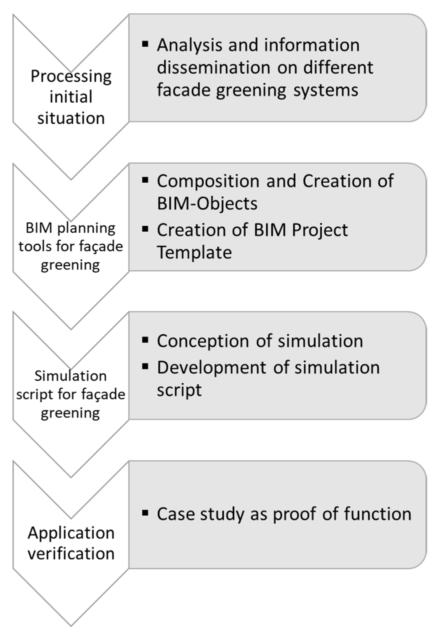
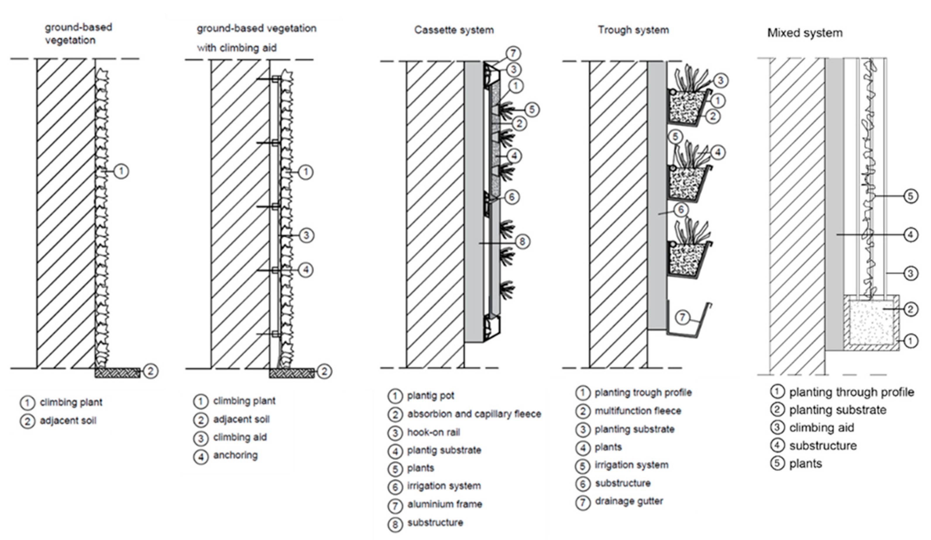
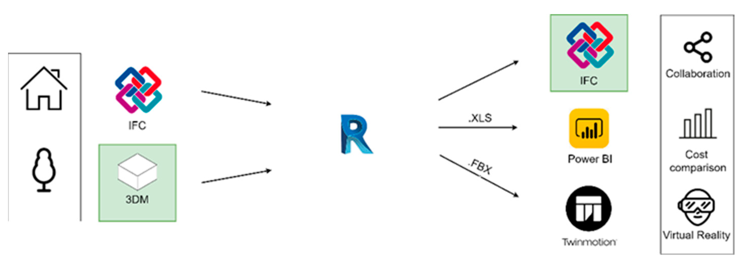
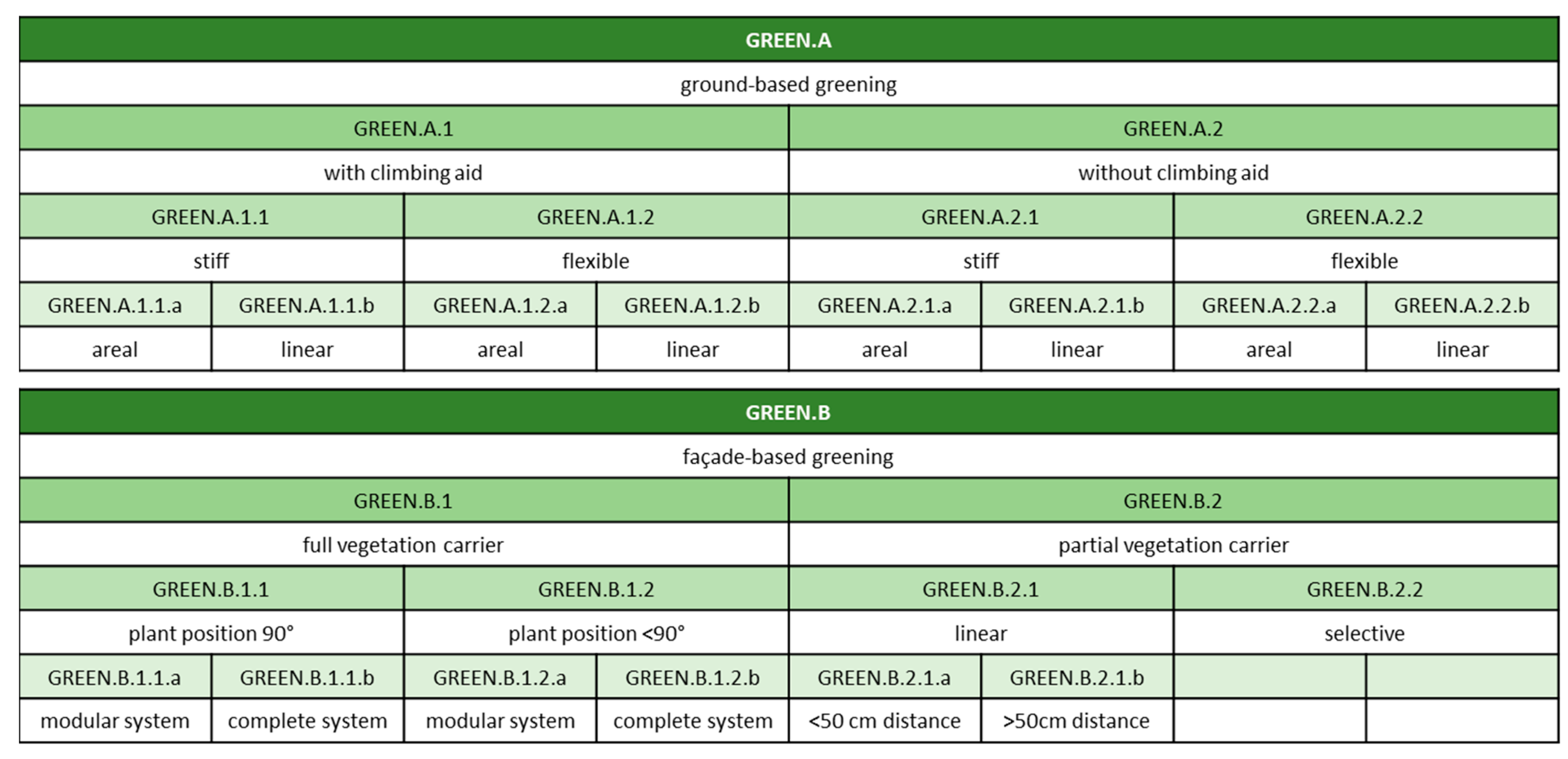
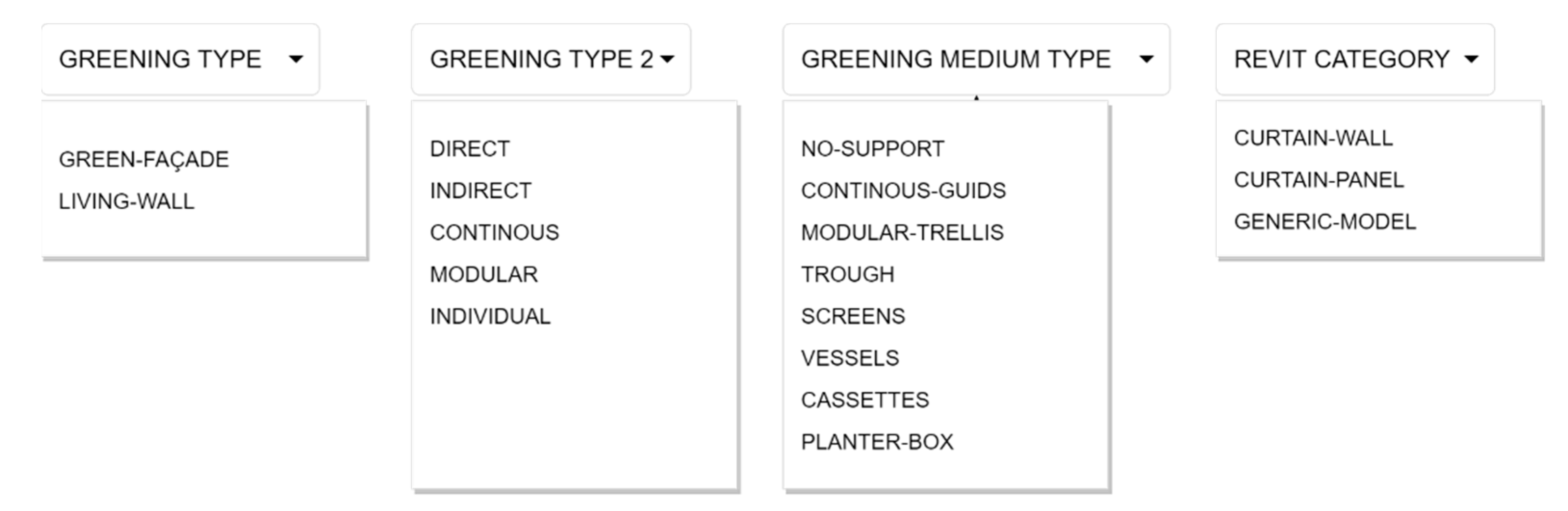
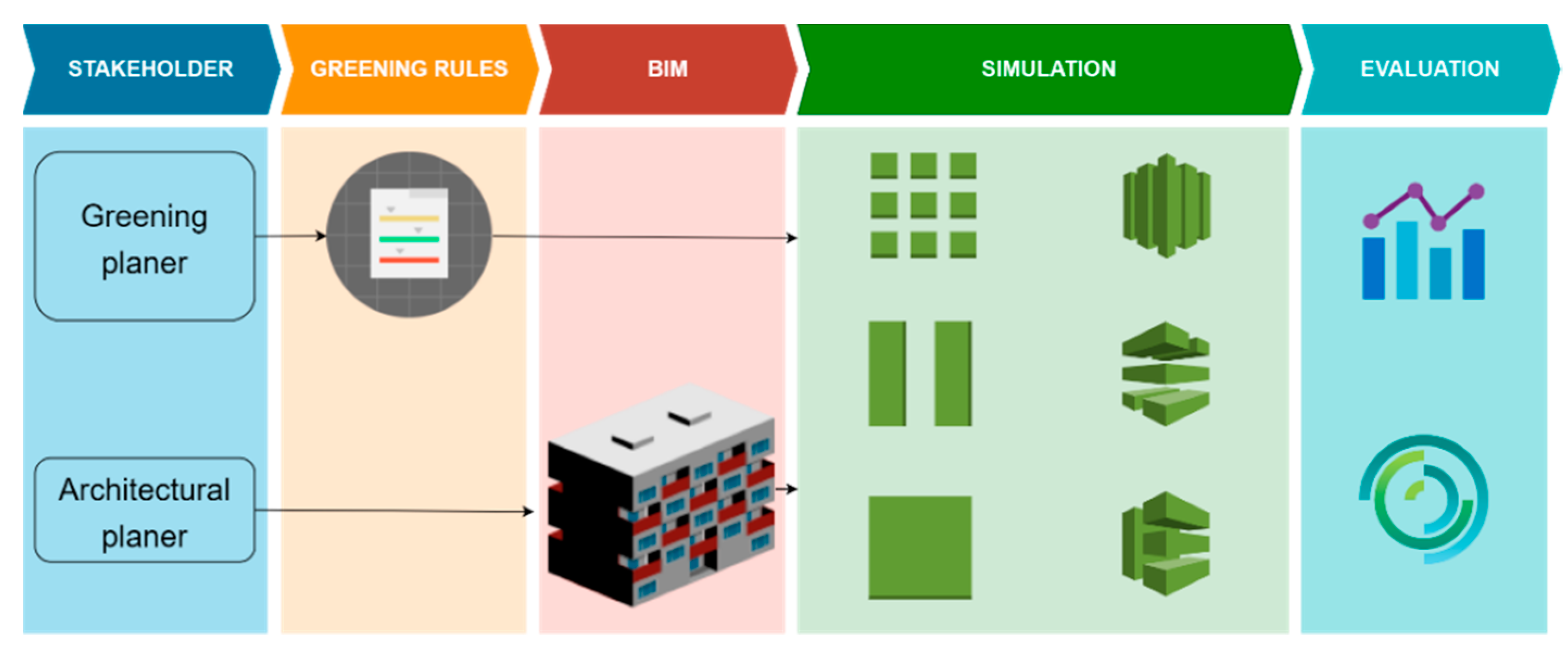
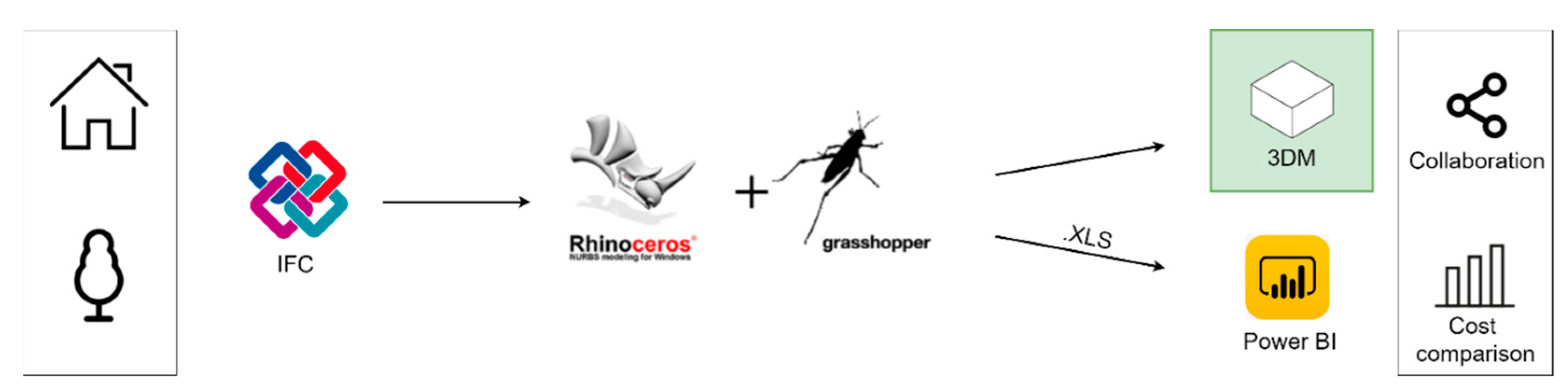
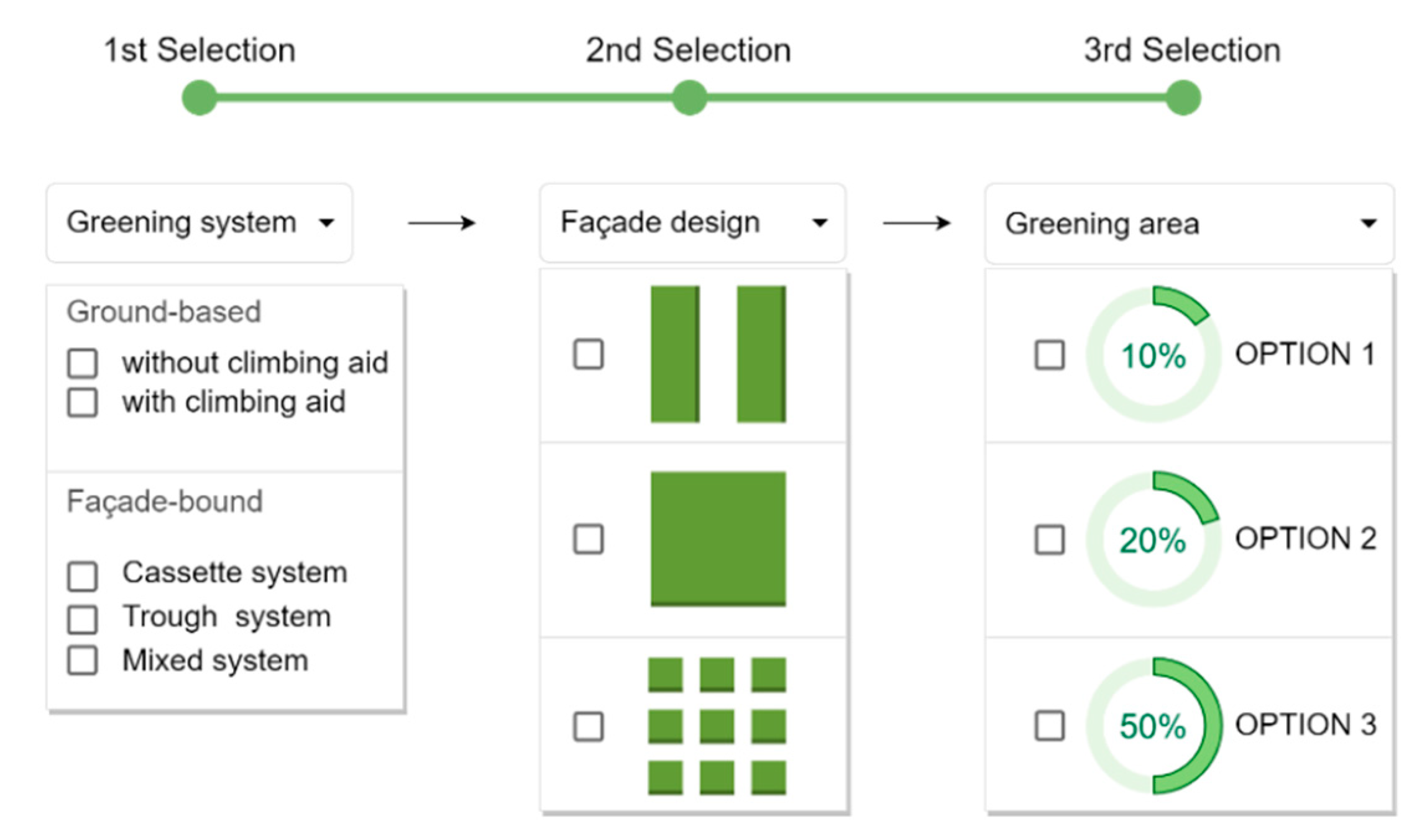
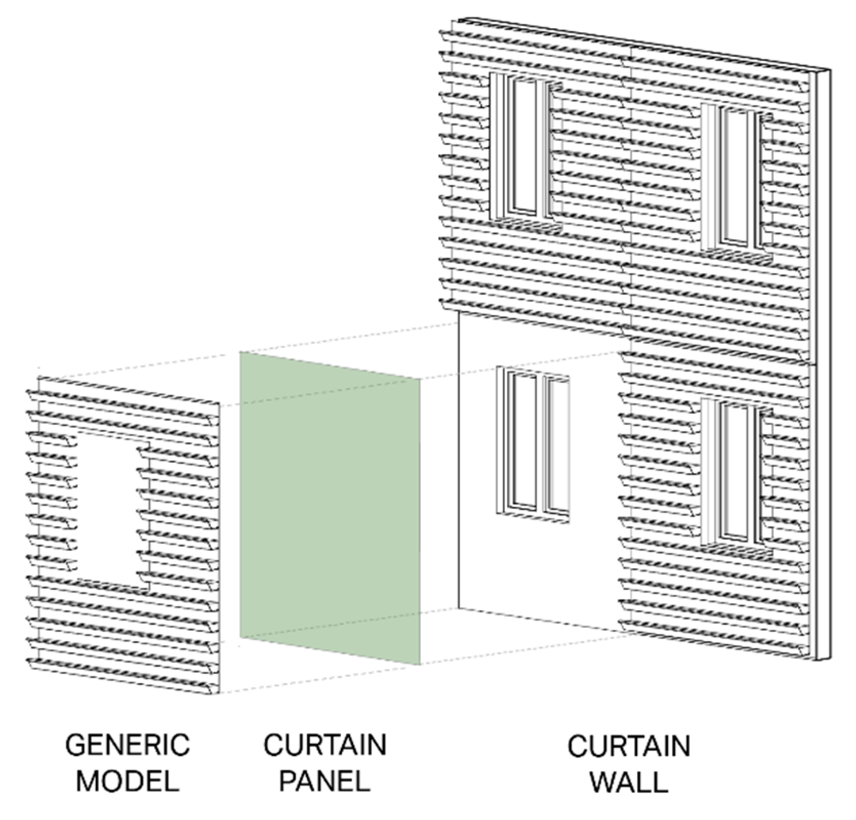
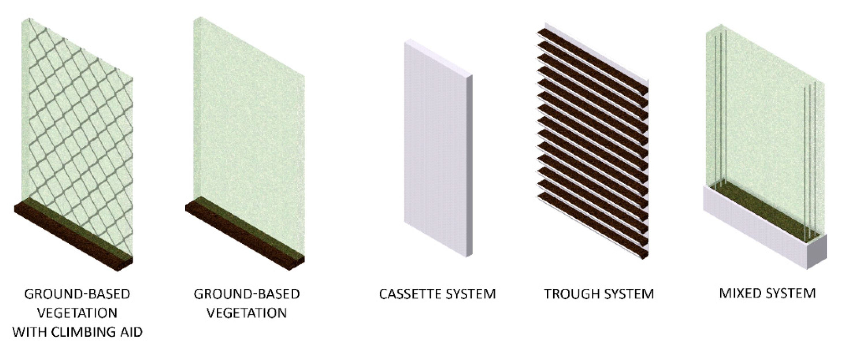
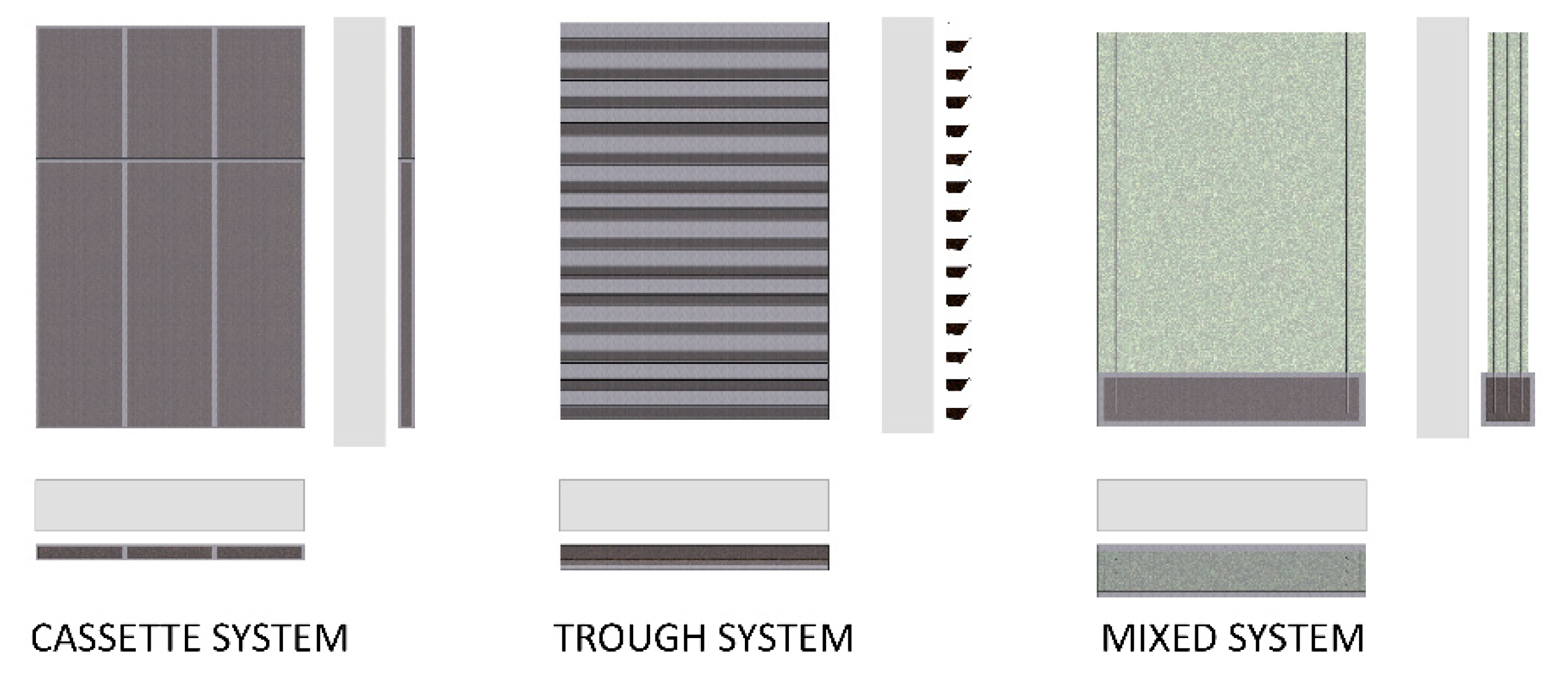
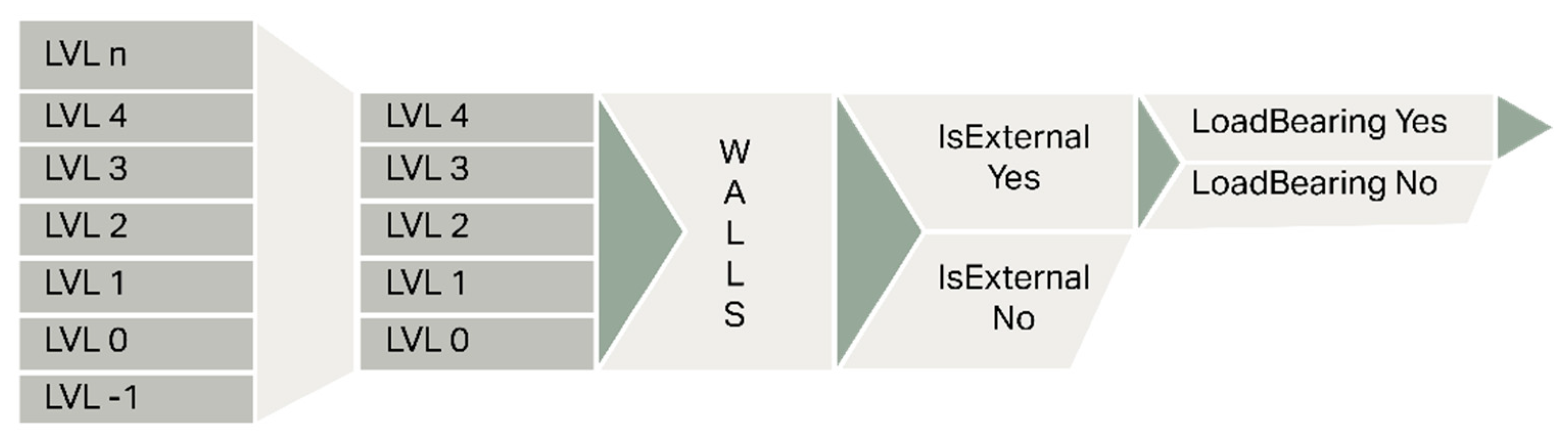
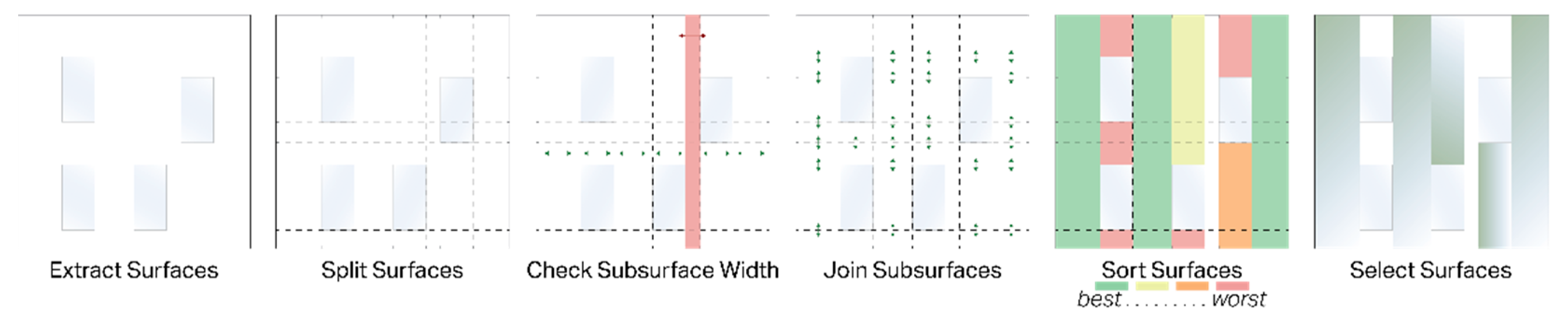
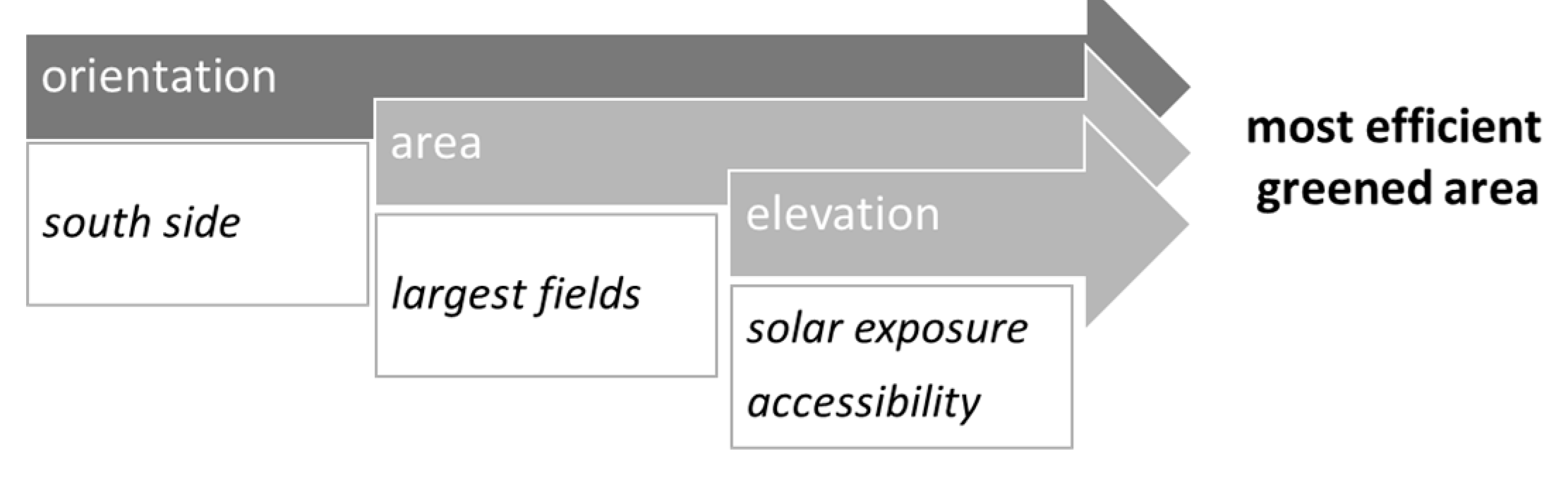
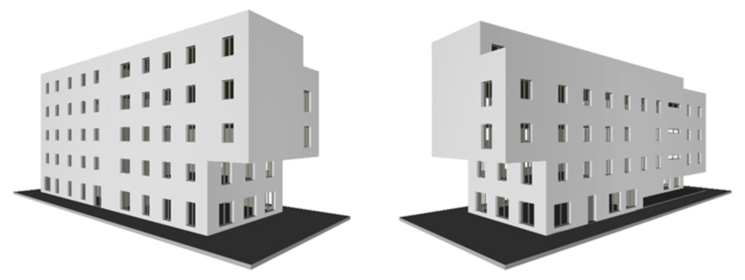
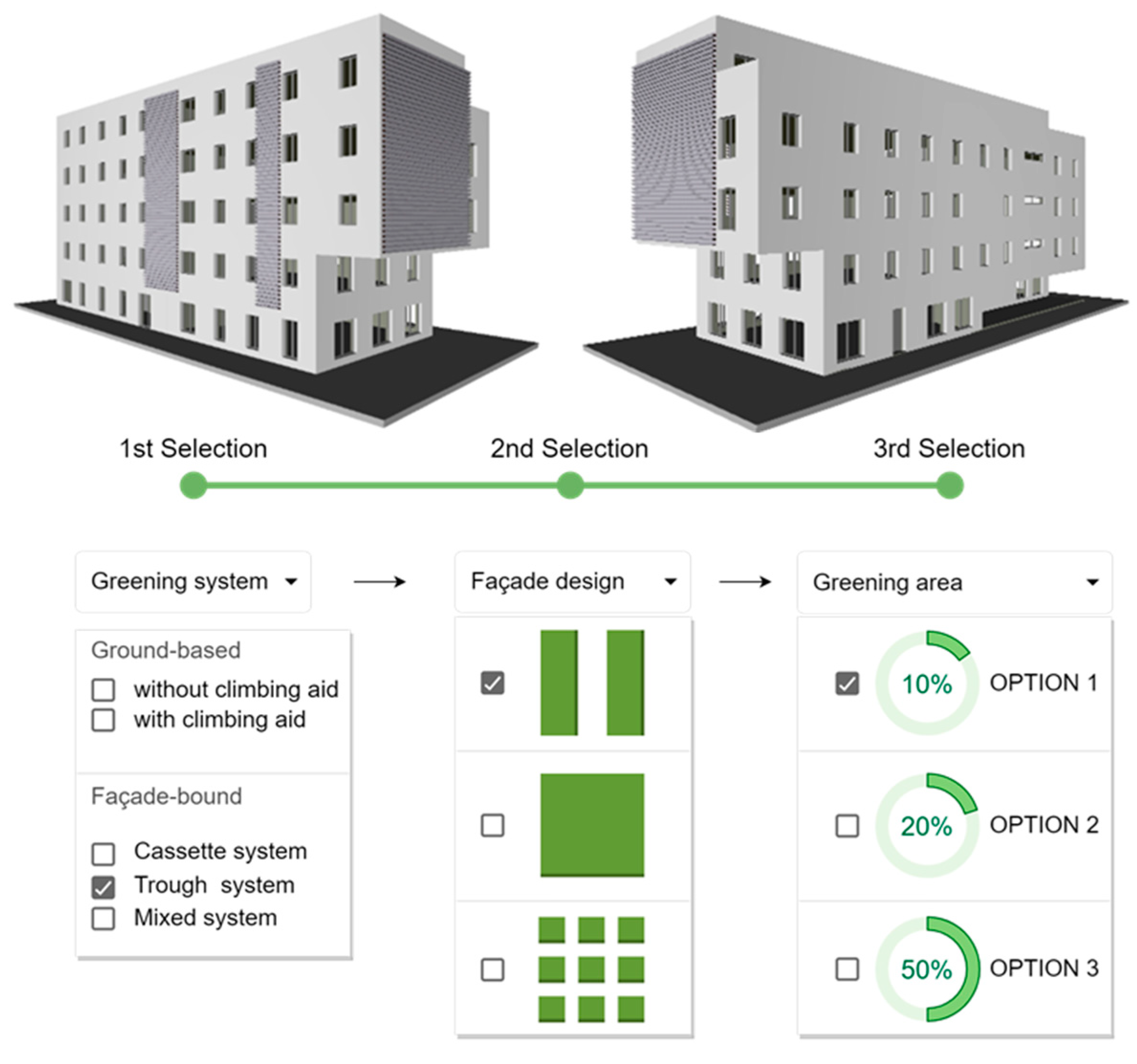
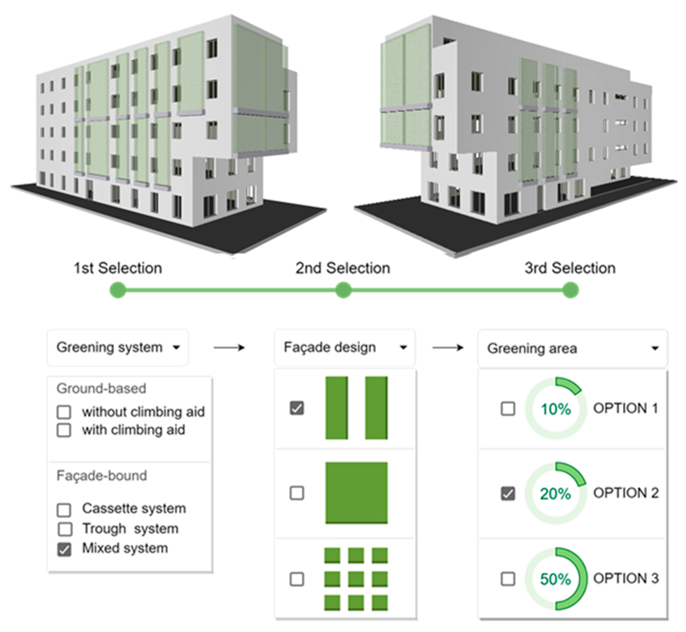
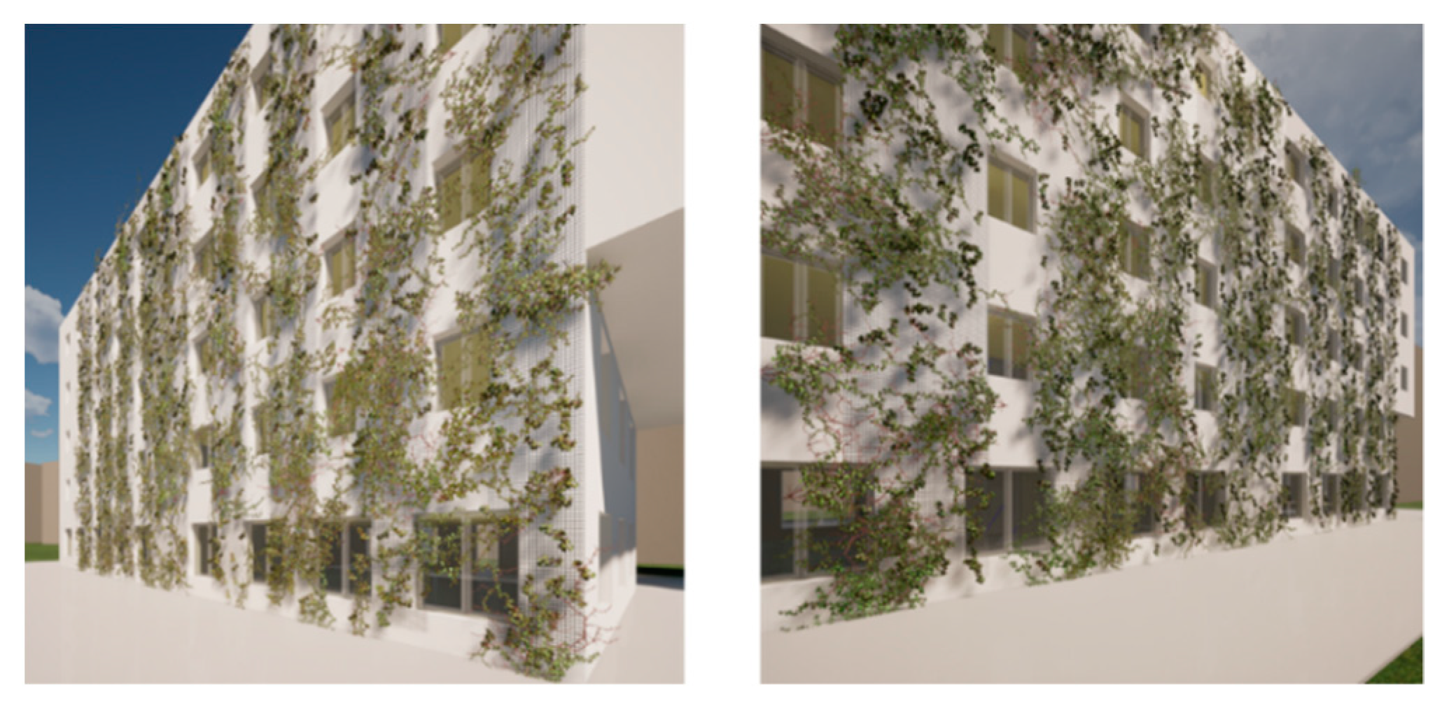
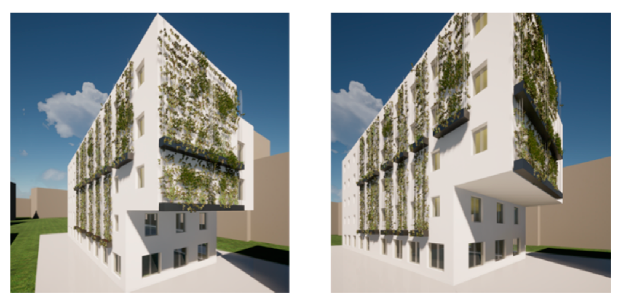
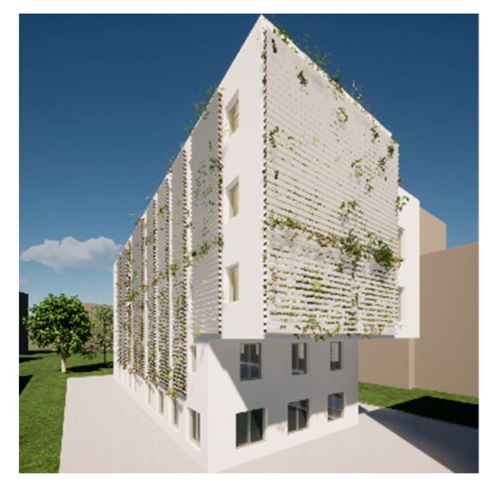
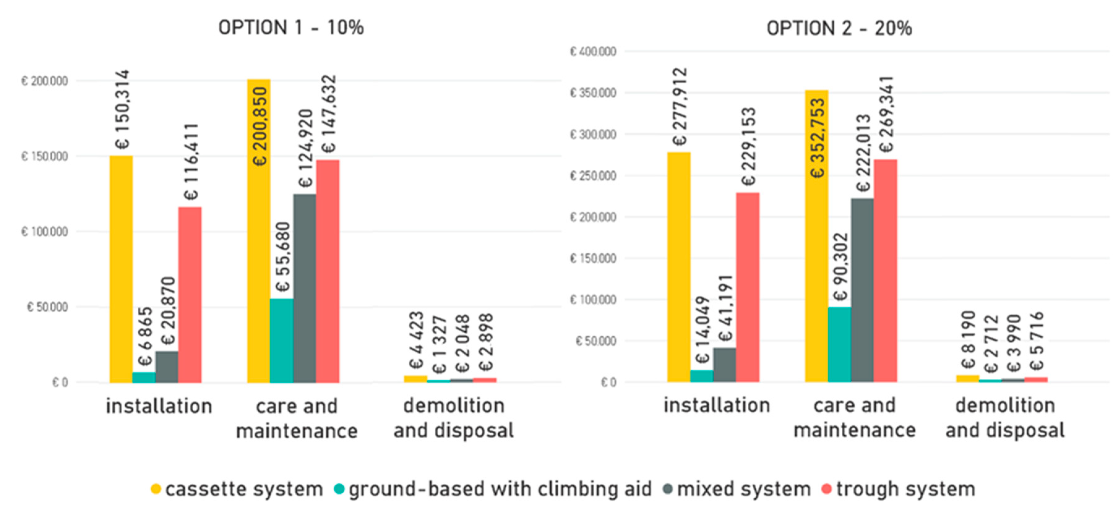
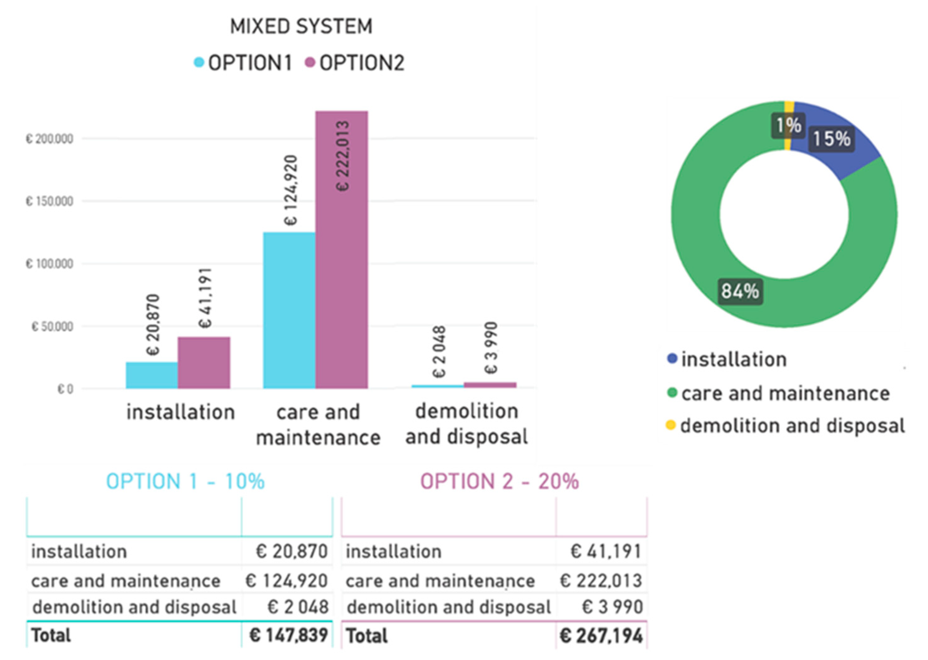
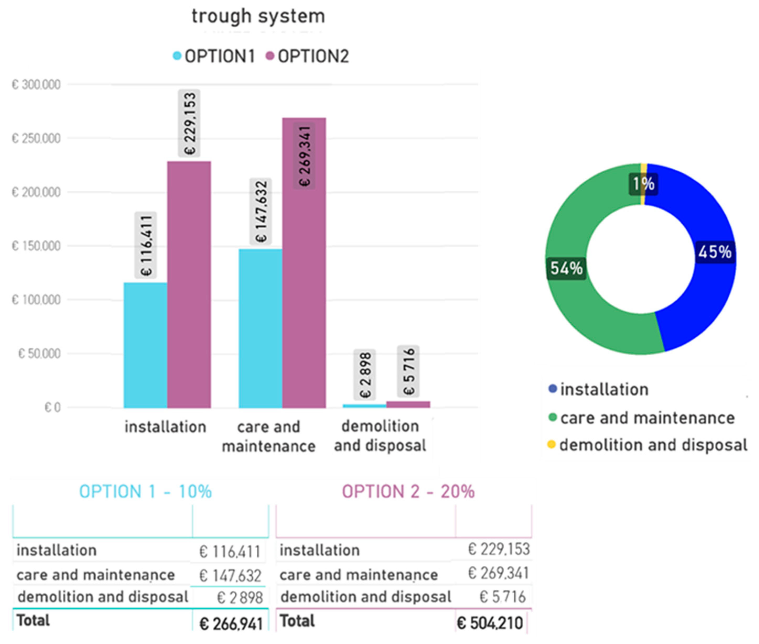
| Name | Greening System | Suitable for Pots | Sun Exposure | Sun Direction | Position on the Façade |
|---|---|---|---|---|---|
| Sedum floriferum | façade-bound | yes | sun | south | high to low |
| Seslaria caerulea | façade-bound | yes | sun to partial shade | south, south-east, south-west | high |
| Luzula nivea | façade-bound | yes | shade | north | high to low |
| Fallopia aubertii | ground-based with climbing aid | no | sun to partial shade | south, south-east, south-west | high |
| Lonicea henryi | ground-based with climbing aid | no | partial-shade to shade | north-east, north-west | high |
| Vitis vinifera | ground-based with climbing aid/mixed system | yes | sun | south | high to low |
| Jasminum nudiflorum | ground-based with climbing aid/mixed system | yes | sun to partial shade | south, south-east, south-west | high |
| Clematis sp. | ground-based with climbing aid/mixed system | yes | sun to shade | south, east, west, north-east, north-west | high |
| Campsis sp. | ground-based without climbing aid | yes | sun | south | high to low |
| Parthenocissus tricuspidata | ground-based without climbing aid | no | sun to partial shade | south, south-east, south-west | high |
| Parthenocissus quinquefolia | ground-based without climbing aid | yes | sun to shade | south, east, west, north-east, north-west | high |
| Hydrangea petiolaris | ground-based without climbing aid | yes | partial-shade to shade | north-east, north-west | high |
Table 2.
Parameters for greening systems.
| Parameter Name | Description |
|---|---|
| GREENING_MATERIAL_GUIDS | Material of climbing aids |
| GREENING_MATERIAL_IRRIGATION-PIPE | Material of irrigation pipe |
| GREENING_MATERIAL_MEDIUM | Material of vegetation carrier |
| GREENING_MATERIAL_MEMBRANE | Material of fleece |
| GREENING_MATERIAL_PLANTS | Planting material |
| GREENING_MATERIAL_SUBSTRATE | Material of substrate |
| GREENING_MAINTENANCE-INTERVALS | Intervals for technical maintenance |
| GREENING_MAINTENANCE-INTERVALS_PLANTING | Intervals for green care |
| GREENING_WATERING-INTERVALS | Watering intervals |
| GREENING_FORM-VARIETY | Form and variety |
| GREENING_DURATION | Duration of greening |
Table 3.
Required parameters for the elements in the initial model.
| IfcWall IfcSlab | Category; Position and dimensions; Function external–internal (IFC: IsExternal [Yes/No]); In contact with the ground [Yes/No]; Load-bearing function (IFC: LoadBearing [Yes/No]); Load-bearing layer (material, layer thickness, other static properties); Non-load-bearing layer (material, layer thickness); Stage; Fire protection |
| IfcWindow IfcDoor | Category; Position and dimensions; Function exterior–interior (IFC: IsExternal [Yes/No]); Basic component; Greening allowed [Yes/No]; Phase; Fire protection. |
Table 4.
Tested variants within the case study with their greenclass number and designation after Figure 4 and the associated greening system after Figure 2.
| Greenclass Number | Greenclass Title (Figure 4) | Greening system (Figure 2) |
|---|---|---|
| Green.A.1.1 | ground-based greening; with climbing aid; stiff | Ground-based vegetation with climbing aid |
| Green.B.1.2 | façade-bound greening; full vegetation carrier; plant position <90° | Mixed system |
| Green.B.2.1 | façade-bound greening; partial vegetation carrier; linear | Trough system |
| Green.B.2.2 | façade-bound greening; partial vegetation carrier; selective | Cassette system |
Table 5.
Cost guidelines for the calculation of façade greening systems for the case study.
| Greening System | Costs | |||||
|---|---|---|---|---|---|---|
| Installation | Care and Maintenance | Demolition and Disposal | ||||
| EUR | EUR/m | EUR/m2 | EUR/year | EUR/m2 | EUR/m2 | |
| ground-based greening—with climbing aid [40] | - | 25 | 50 | 900 | 10 | 10 |
| ground-based greening—without climbing aid [40] | - | 25 | - | 900 | 8 | 5 |
| cassette system [40] | 500 | - | 1.050 | 900 | 50 | 31 |
| trough system [40] | 500 | - | 880 | 900 | 38 | 22 |
| mixed system | 500 | 175 | 120 | 900 | 30 | 20 |
Table 6.
Extract of cost calculation table for case study.
| Greening System | Greenclass Number | Option | Costs in EUR | |||
|---|---|---|---|---|---|---|
| Installation | Care and Maintenance | Demolition and Disposal | Total | |||
| ground-based greening—with climbing aid | Green.A.1.1 | 10% (135 m2) | 6.864 | 55.680 | 1.327 | 63.872 |
| Mixed system | Green.B.1.2 | 10% (135 m2) | 150.314 | 200.850 | 4.423 | 355.587 |
| Trough system | Green.B.2.1 | 10% (135 m2) | 116.411 | 147.631 | 2.897 | 266.940 |
| Cassette system | Green.B.2.2 | 10% (135 m2) | 22.231 | 129.859 | 2.147 | 154.238 |
| ground-based greening—with climbing aid | Green.A.1.1 | 20% (270 m2) | 14.049 | 90.301 | 2.712 | 107.063 |
| Mixed system | Green.B.1.2 | 20% (270 m2) | 277.912 | 352.752 | 8.190 | 638.855 |
| Trough system | Green.B.2.1 | 20% (270 m2) | 229.152 | 269.340 | 5.716 | 504.209 |
| Cassette system | Green.B.2.2 | 20% (270 m2) | 44.018 | 229.640 | 4.142 | 277.810 |
Table 7.
Trough system Option 2 (Green.B.2.1)—quantity determination material: aluminum and substrate.
Table 7.
Trough system Option 2 (Green.B.2.1)—quantity determination material: aluminum and substrate.
| Count Panel | Panel Width | Panel Height | Count Trough per Panel | Material Length Aluminum | Material Volume Substrate |
|---|---|---|---|---|---|
| 8 | 1.65 m | 2.94 m | 14 | 184.83 m | 1.93 m3 |
| 4 | 1.76 m | 2.94 m | 14 | 98.45 m | 1.03 m3 |
| 3 | 1.87 m | 2.94 m | 14 | 78.37 m | 0.82 m3 |
| 4 | 2.06 m | 2.94 m | 14 | 115.36 m | 1.20 m3 |
| 4 | 2.16 m | 2.94 m | 14 | 120.96 m | 1.26 m3 |
| 3 | 2.49 m | 2.94 m | 14 | 104.52 m | 1.09 m3 |
| 4 | 3.69 m | 2.94 m | 14 | 206.79 m | 2.16 m3 |
| 3 | 7.81 m | 2.94 m | 14 | 328.02 m | 3.42 m3 |
| Total 33 | 1.237.30 m | 12.90 m3 |
Table 8.
Result of tender positions for the trough system Option 2 (Green.B.2.1).
| Position | Short Description | Quantity | Unit | |
|---|---|---|---|---|
| 687210 | 687210CZ | Partial vegetation support—plant trough profiles stainless steel | 1974.58 | m |
| 687211 | 687211AZ | Partial vegetation support—vegetation technology | 1974.58 | m |
| 687212 | 687212BZ | Partial vegetation support—planting with drip irrigation 9 × 9 6/m | 11,848.00 | pieces |
| 687213 | 687213AZ | Partial vegetation support—depot fertilization | 1974.58 | m |
| 687410 | 687410AZ | Growing care | 15.00 | FR |
Publisher’s Note: MDPI stays neutral with regard to jurisdictional claims in published maps and institutional affiliations. |
© 2021 by the authors. Licensee MDPI, Basel, Switzerland. This article is an open access article distributed under the terms and conditions of the Creative Commons Attribution (CC BY) license (https://creativecommons.org/licenses/by/4.0/).
Share and Cite
MDPI and ACS Style
Hollands, J.; Korjenic, A. Evaluation and Planning Decision on Façade Greening Made Easy—Integration in BIM and Implementation of an Automated Design Process. Sustainability 2021, 13, 9387. https://doi.org/10.3390/su13169387
AMA Style
Hollands J, Korjenic A. Evaluation and Planning Decision on Façade Greening Made Easy—Integration in BIM and Implementation of an Automated Design Process. Sustainability. 2021; 13(16):9387. https://doi.org/10.3390/su13169387
Chicago/Turabian StyleHollands, Jutta, and Azra Korjenic. 2021. "Evaluation and Planning Decision on Façade Greening Made Easy—Integration in BIM and Implementation of an Automated Design Process" Sustainability 13, no. 16: 9387. https://doi.org/10.3390/su13169387
Note that from the first issue of 2016, this journal uses article numbers instead of page numbers. See further details here.