Article

Effect of Intake Air Temperature and Premixed Ratio on Combustion and Exhaust Emissions in a Partial HCCI-DI Diesel Engine

1
School of Mechanical Engineering, Engineering Campus, Universiti Sains Malaysia, Nibong Tebal 14300, Penang, Malaysia
2
Department of Engineering, School of Engineering, Computing and Built Environment, UOW Malaysia KDU Penang University College, 32, Jalan Anson, Georgetown 10400, Penang, Malaysia
3
Department of Engineering, School of Science and Technology, Nottingham Trent University, Nottingham NG11 8NS, UK
4
Faculty of Mechanical Engineering, Industrial University of Ho Chi Minh City, Ho Chi Minh City 700000, Vietnam
5
Department of Fundamentals of Mechanical Engineering, Faculty of Automotive, Mechanical, Electrical and Electronic Engineering (FAME), An Phu Dong Campus, Nguyen Tat Thanh University, Ho Chi Minh City 729800, Vietnam
*
Authors to whom correspondence should be addressed.
Sustainability 2021, 13(15), 8593; https://doi.org/10.3390/su13158593
Submission received: 23 June 2021 / Revised: 16 July 2021 / Accepted: 24 July 2021 / Published: 1 August 2021

Abstract

:
Homogeneous charge compression ignition (HCCI) is considered an advanced combustion method for internal combustion engines that offers simultaneous reductions in oxides of nitrogen (NOx) emissions and increased fuel efficiency. The present study examines the influence of intake air temperature (IAT) and premixed diesel fuel on fuel self-ignition characteristics in a light-duty compression ignition engine. Partial HCCI was achieved by port injection of the diesel fuel through air-assisted injection while sustaining direct diesel fuel injection into the cylinder for initiating combustion. The self-ignition of diesel fuel under such a set-up was studied with variations in premixed ratios (0–0.60) and inlet temperatures (40–100 °C) under a constant 1600 rpm engine speed with 20 Nm load. Variations in performance, emissions and combustion characteristics with premixed fuel and inlet air heating were analysed in comparison with those recorded without. Heat release rate profiles determined from recorded in-cylinder pressure depicted evident multiple-stage ignitions (up to three-stage ignition in several cases) in this study. Compared with the premixed ratio, the inlet air temperature had a greater effect on low-temperature reaction and HCCI combustion timing. Nonetheless, an increase in the premixed ratio was found to be influential in reducing nitric oxides emissions.

1. Introduction

The internal combustion engine was invented over a century ago as a replacement for the steam engine. Due to their superior weight to power ratio which grants them higher mobility, they have assumed the lead role in powering transportation. Put simply, two major types of internal combustion engines are spark ignition (SI) and compression ignition (CI) engines. SI engines generally have lower thermal efficiency than CI engines, which are more favourable in heavy duty uses. However, the former emit less nitrogen oxides (NOx) and particulate matter (PM) into the environment. Over the past few years, global greenhouse gas emissions have continued to grow despite efforts to mitigate climate change. Besides this, among emissions that are commonly found in internal combustion engines are NOx, carbon monoxide (CO), smoke and PM. Unburnt hydrocarbon (HC) also makes up part of internal combustion engine exhaust due to the use of carbon-rich fossil fuels. The release of those gases due to the combustion of fuel in engines has become a public concern since they threaten not only the environment but are also detrimental to human well-being.
Recently enforced emissions regulations that emphasize a reduction in greenhouse gas emission and improvement in fuel economy have pushed automakers to develop cleaner technologies to meet the stringent requirements. The automotive sector is poised to be a main source of emissions in the year 2030. The Kyoto protocol aims at a more sustainable imminent future by decreasing pollution secreting energy sources [1]. As a result, improvements in SI and CI engine combustion aspects such as optimised fuel injection (FI) timing, altered combustion chamber shape and FI with higher pressure have been introduced over the last decades to make internal combustion engines cleaner and more efficient. Nevertheless, these techniques were not able to substantially resolve SI and CI engines’ emission problems. In search of better solutions, attempts to improve contemporary combustion strategies, including low-temperature combustion (LTC), that combine the benefits of both fewer emissions and greater thermal efficiency with a lower combustion temperature have been initiated [2]. Homogeneous charge compression ignition (HCCI) is one of the LTC strategies introduced by Onishi et al. [3] as an attempt to improve combustion stability in gasoline-fuelled engines. It utilises the auto-ignition of well-premixed fuel–air mixture channelled into engine cylinders by piston intake stroke to achieve combustion near the top dead centre (TDC) when the mixture is being compressed and detonated. Since then, many researchers had adapted HCCI combustion in engines operating with various fuels such as alcohols, diesel and biofuels and reported its potential to revolutionise the automobile sector [4,5,6,7].
Generally, HCCI combustion offers reductions in NOx and smoke emissions, defying the well-known NOx–smoke trade-off with superior fuel flexibility [8,9,10]. Due to fuel ignitions at multiple spots spontaneously in HCCI combustion, the formation of a localized high-temperature zone that favours thermal NOx formation through the Zeldovich mechanism can be prevented [8]. Furthermore, the combustion of homogeneous premixed mixture gives rise to the absence of a fuel-rich zone to assist soot formation. Several researchers have also reported comparable or even higher efficiency with the use of HCCI combustion than conventional SI and CI modes [9,11,12]. With its merits, the HCCI strategy has caught the attention of researchers and manufacturers as a promising alternative especially to overcome high NOx emissions from diesel engines. However, the use of HCCI combustion in engines is also associated with difficulties, particularly in its combustion phase control, cold start, limited operating range and premixed mixture preparation. Engine knocking at high load conditions and misfiring due to late auto-ignition when employing HCCI take a toll on engine performance and may contribute to engine wear and damage [13,14]. Unfortunately, higher emissions of unburnt HC and CO also were found with HCCI combustion [15,16,17]. To overcome the pitfalls of HCCI, combustion modes extended from HCCI such as premixed charge compression ignition (PCCI), homogeneous charge diesel combustion (HCDC) and stratified charge compression ignition (SCCI) were proposed. Besides this, control strategies and systems to achieve designed ignition timing and the start of combustion (SOC) of the fuel mixture have been studied by many researchers [18,19,20,21].
One of the extended combustion strategies is premixed/direct injection HCCI combustion or HCCI-DI that employs the preparation of a homogeneous fuel–air mixture upstream of the cylinder intake manifold and directly injected fuel to trigger combustion near TDC. HCCI-DI has been claimed to provide a wider operating range for the engine with greater thermal efficiency than engines running with pure HCCI combustion [22]. Furthermore, this combustion strategy also exhibits advantages over its predecessor with relatively lower HC and CO emissions [18,23]. The degree of homogeneity of the charge, which is affected by its preparation method, is the key in achieving fuel mixture auto-ignition for smooth applications of the HCCI concept in engines. In fact, fuel–wall interactions when using the internal preparation of the charge in the cylinders may give rise to wall wetting or impingement problems that are highly disadvantageous for HC emissions. Out of the many proposed methods, the most convenient and also effective approach is premixing the fuel and air by port fuel injection (PFI) as applied in a conventional SI engine [24]. This method offers sufficient time for the dispersion of fuel and fuel–air mixture formation in engine cylinders before ignition. According to Ganesh et al. [25], PFI is a strategy that offers economic benefits as it does not require engine modification in the first place, while producing notably few emissions under light load conditions.
Similarly, Bendu et al. [15] also point out the superior mixture homogeneity that can be achieved through PFI compared to other injection methods. Lee et al. [26] show improvement in exhaust emission by employing an electronic port injection system with premixed gasoline in a direct-injection diesel engine. The authors report reduced NOx and smoke emission with an increased premixed ratio in the engine. Nevertheless, it is especially challenging to prepare diesel premixed charge through PFI due to its lower volatility compared to gasoline and alcohol fuels [13,18]. Diesel exhibits a higher viscosity that consequently leads to difficulties in diesel atomization during the injection. In fact, the type of premixed fuel has a determinant role in HCCI-DI engine combustion characteristics. In an attempt to study partial HCCI combustion characteristics, Lee et al. [26] report dissimilarities in the uses of premixed gasoline and premixed diesel. The former was found to combust with single-stage combustion, while the latter demonstrated noticeable cool flame combustion before TDC [27]. Besides the type of fuel used, combustion control may also be accomplished by manipulating parameters such as the intake air temperature (IAT), boost pressure, premixed ratio, fuel equivalence ratio and engine compression ratio [8].

Purpose of Study

In spite of previous research focusing on partial HCCI strategy on a direct-injection diesel engine, investigation of the correlations between engine performance and exhaust emissions with combustion using premixed diesel fuel is very limitedly accessible. Furthermore, in this research, a homogenous mixture of diesel and air was created using an air-assisted FI system in addition to conventional PFI. Fuel atomisation through this method was successfully applied in two-stroke and four-stroke engines [28]. Koci et al. [29] report the potential of external air-assisted injection in fuel-air mixing enhancement, achieved by lowering the fuel local equivalence ratio. However, only a few studies of the application of this technique on partial HCCI engines are reported. Hence, this study aims to investigate the individual effects of the premixed fuel ratio and IAT on a partial HCCI engine to reduce the existing research gaps. The results of this study will allow us to learn more about the controlling of auto-ignition, which is still the main barrier for the commercialisation of this technology. Comprehensive investigations including engine performance, emissions and combustion characteristics under such set-up are also intended to provide a better understanding of the potential of the partial HCCI strategy as an improvement upon currently dominant SI and CI engines.

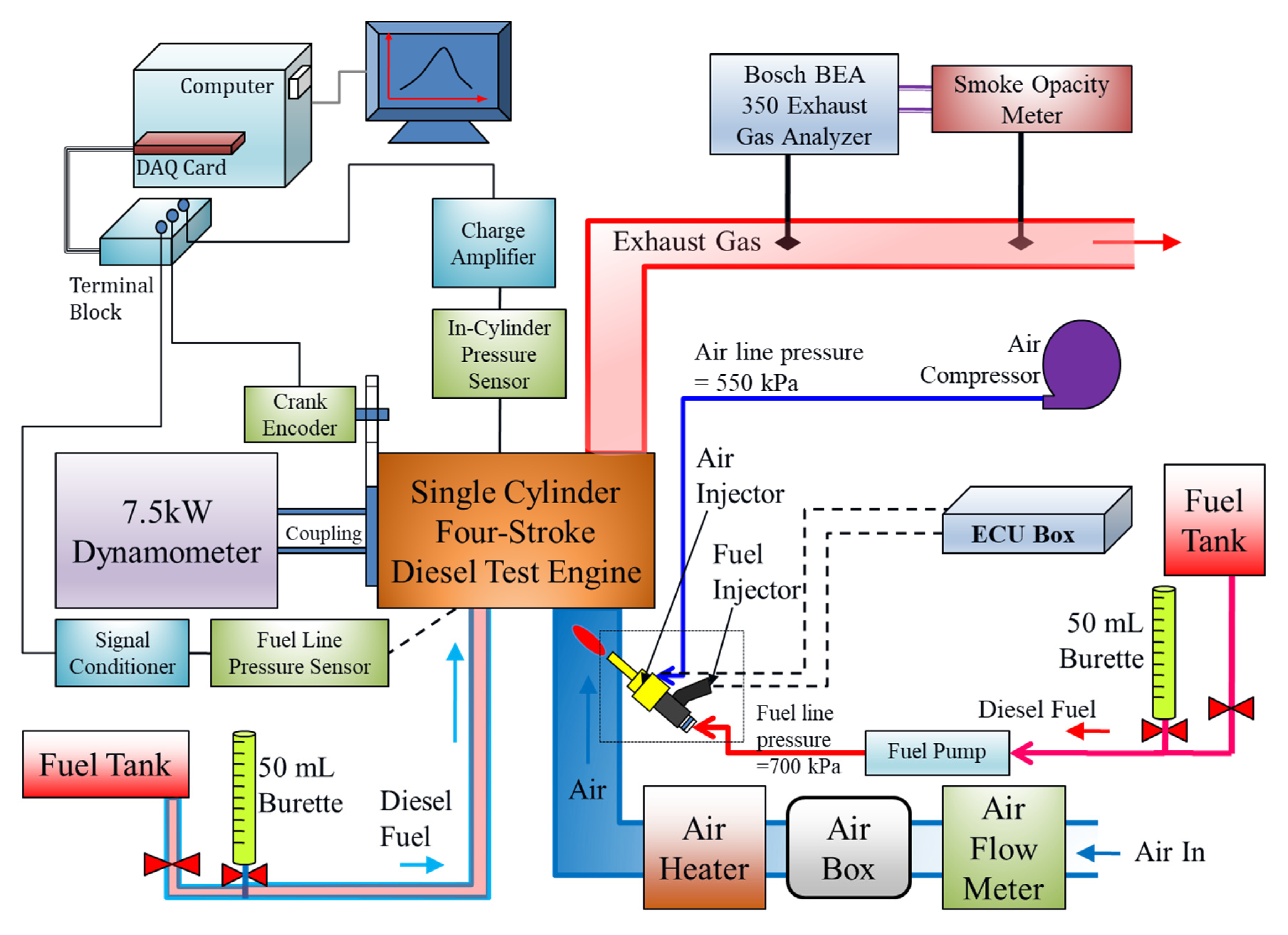
2. Experimental Apparatus and Procedure

2.1. Engine

A single-cylinder, four-stroke direct-injection CI engine was employed to carry out tests in the present study. Slight modifications on the test engine were made to add an air-assisted PFI system to it. The specifications of the test engine are presented in Table 1. The set-up of the apparatus, including the test engine, hardware and software that were necessary to control engine parameters like IAT and auxiliary fuel injection (FI) rate, is as shown in Figure 1.

2.2. Fuel Injection System

In this work, an FI system was adapted to provide air-assisted atomisation of the liquid fuels. The air-assisted FI system comprised a 700 kPa fuel metering injector and a 550 kPa air injector. The FI was timed to coincide with the cylinder’s intake stroke and was made into the intake port just upstream of the intake manifold. Two separate ECUs, each connected to a Hall Effect inductive proximity sensor, were used to provide precise controls on injection timing and the operating duration of the injectors. The fuel vaporiser plumes produced three series of injections into a 2 L flask under atmospheric conditions as shown in Figure 2, where each of the images captured demonstrates a subsequent 2 mL FI. As revealed in the images, this injection strategy produced a finely atomised fuel spray.

2.3. Fuel Consumption Measurement

In this study, fuel consumption for both the diesel direct injection and PFI systems were measured volumetrically. This method employed a glass burette of known volume with volume level markings. The time duration for the consumption of a certain volume of fuel was measured by a data logger system. The volumetric flow rate was calculated by a quotient of the volume measured by the time taken. In this experiment, two separate burettes, each of a 50 mL capacity, were used to measure the volumetric fuel consumption of both the diesel direct injection and PFI systems. To enhance measurement accuracy, a fully automated volumetric-type fuel-flow measuring system was used for each fuelling system. The system included a 50 mL capacity glass burette (A), which had multiple slotted interrupter photosensors (B1 to B5) spaced evenly along its length, each located at a known fuel level to minimize human error in measuring the fuel level against the marks on the burette. The photosensors were arranged perpendicularly to the burette to allow measurement by the infrared light beam transmitted parallel to the fuel-level marks on the burette. Besides this, to ease the fuel refilling process, a magnetic refilling valve (C) was integrated into this system.
It was assumed that the fuel level would initially be at the upper portion (B1 level) of the burette. By keeping the magnetic refilling valve closed, the flow from the fuel tank to the burette was stopped and the fuel level fell at a rate dependent only on the engine consumption. When the fuel level fell below each of the slotted interrupter photosensors, the infrared light beam from the emitter was transmitted to the opposite detector and converted into an electrical signal. These signals together with their time of occurrence were recorded by a data logger system. Thus, the fuel consumption in volumetric units could be obtained by dividing the relative volume (the pre-determined fuel volume between the successive sensors) by the time duration. When the fuel level reached the lower measuring level (B5), the magnetic refilling valve was triggered to open to allow fuel from the tank to flow into the burette. The refilling process was terminated again when the fuel level reached the upper portion (B1 level) of the burette. These automatic refilling processes were repeated throughout the experiment to ensure a continuous supply of fuel into the burette.

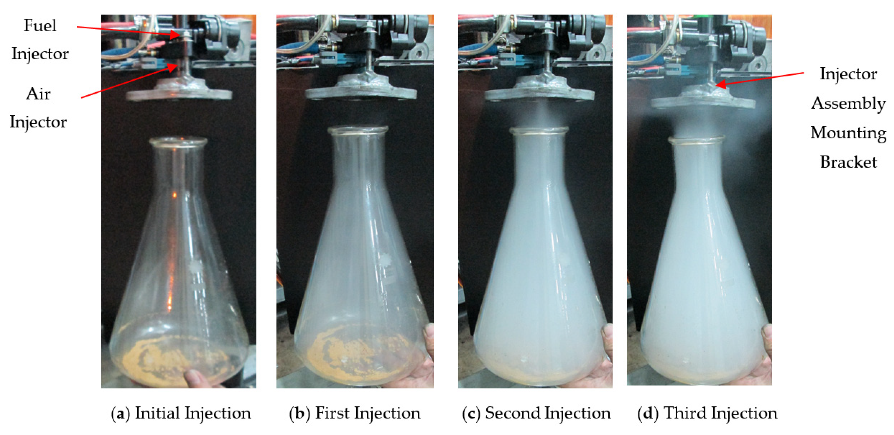
2.4. Auxiliary Fuel Injector Calibration Protocol

Prior to the installation of the FI system on the engine, both the fuel and air injectors underwent calibration processes. The bench test was carried out with an ECU with varying injection pulse width to determine the amount of fuel delivered. A commercially available Arduino UNO™ microcontroller board was used to interface with the ECUs by generating a consistent square wave signal that mimics the engine speed signal. In addition, the controller was also connected with the slotted interrupter photosensors and a magnetic refilling valve for the automatic fuel consumption measurement. The number of injection counts and the instances when the fuel level fell below each of the slotted interrupter photosensors were all recorded by using LabVIEW software. Thus, the average fuel volume per injection pulse for a specific injector pulse width was obtained by dividing the relative volume (the pre-determined fuel volume between the successive sensors) by the injection count. Alternatively, the fuel flow rate could be given in terms of fuel mass per injection pulse by multiplying the fuel volume by the density of the fuel. The experimental results revealed that the fuel mass/injection pulse varied proportionally to the injector pulse width.

2.5. Intake Air Systems and Exhaust Emission Measurements

To minimise pressure pulsations of the intake gases and provide higher engine operational stability, a surge tank was installed to enable airflow measurement. The surge tank was installed upstream of a 5.5 kW heater in the engine intake system. The power supplied to the heater was precisely controlled to maintain the intake air at a particular temperature. The flow rate of the intake air to the engine was determined using a hot-film-type air-mass flow meter. Pressurised clean air was supplied to the air injector through an air compressor to enable better fuel atomisation before it entered the intake manifold. On the other hand, exhaust emission measurements were conducted by a Bosch BEA 350 exhaust gas analyser. The concentration of carbon monoxide (CO), carbon dioxide (CO2), unburned hydrocarbon (HC), oxygen (O2) and nitric oxide (NO) were measured and analysed. At the same time, an integrated smoke opacity meter was also employed to determine the smoke opacity of the engine exhaust.

2.6. Data Acquisition

A moderate-speed data logging system was established by the implementation of an Advantech USB multifunction module. The LabVIEW program was employed to provide the means of controlling the hardware in this experiment, including the real-time monitoring of the intake air flow rate, fuel flow rate, engine speed and load cell signals. Besides this, the changes in engine coolant and IAT prior to heating along with ambient temperature were monitored using an Advantech USB 8-ch thermocouple. In this experiment, the fuel combustion analysis was carried out by measuring the in-cylinder pressure with a Kistler 6125B-type pressure sensor. The charge signal output from the pressure sensor was processed and conditioned by a PCB model charge-to-voltage converter. The data registered was further processed to determine the heat release rate during the combustion. A high-precision Leine and Linde incremental encoder (model: 632-00685-1) with 720 pulses per revolution was employed to monitor the shaft rotation. Besides this, a computer was used as the data acquisition unit, which was equipped with 14-bit resolution, a 2 MS/s sampling rate and 4 analogue input channels to simultaneously sample and synchronize the in-cylinder pressure and encoder signals. Further processing of the recorded data was then carried out by MATLAB software.

2.7. Dynamometer

A single-phase AC synchronous electrical generator was employed to absorb the engine load from the test engine. The drive end of the dynamometer shaft carried a 30-toothed wheel that was used with a magnetic pick-up to provide the speed measurement. A torque arm was attached to the generator housing on a horizontal centreline and the force exerted by the housing attempting to rotate the torque arm was measured with a strain gauge load cell at a radius of 245 mm. The torque was calculated as the product of the force measured by the load cell and the length of the torque arm. The power output from the generator was dissipated to a load bank consisting of three units of 3 kW screw-in water immersion heaters. A dynamometer controller featuring a digital PID (Proportional Integral Derivative) closed-loop control method was employed to keep the engine speed constant throughout the experiment. The controller pulse width modulated the power transferred to the coils via a field-effect transistor.

2.8. Experimental Procedure

During the start of the experiment, the test engine was initiated in direct injection mode with no load exerted to allow the engine to warm up. When the operating temperature achieved the optimum value of 80 °C, tests involving variations in the premixed ratio, with rp up to 0.6 and IAT up to 100 °C, were started. The premixed ratio was controlled by adjusting the pulse injection widths of the air-assisted PFI system and also the engine direct injector. The actual premixed ratio was then determined by fuel consumption results. The term rp represents the ratio of the energy of the premixed fuel Qp to the total energy Qt; the value of rp was calculated by Equation (1).
r p = Q p Q t = m p h p m p h p + m d h d  
where mp is the mass of the premixed fuel, md is the mass of the directly injected fuel and h is the lower heating value. The subscripts p and d denote premixed and directly injected fuel respectively. Several physiochemical properties of the diesel fuel employed are listed in Table 2. Since the direct-injected fuel and premixed fuel chosen in this study was diesel, the heating values for both fuels were the same as shown here—hence hp = hd.
The engine and test conditions used in this experiment are summarised in Table 3. The tests conducted can be divided into two main parts. Firstly, the value of rp was varied from 0 up to 0.6 and the subsequent effects of rp on HCCI combustion, engine performance and emissions were studied. The engine was run at a constant 1600 rpm speed and load of 20 Nm at all operating points. For each of the operating conditions, the end of injection (EOI) timing for the premixed fuel was held constant, whereas the start of injection (SOI) timing was altered according to the injection pulse width setting. In the second part of this study, the effects of intake temperature were investigated. The premixed fuel ratio was kept around a value of rp of 0.5 while the IAT was manipulated, ranging from 40 to 100 °C.

3. Results and Discussion

3.1. Effect of Premixed Ratio

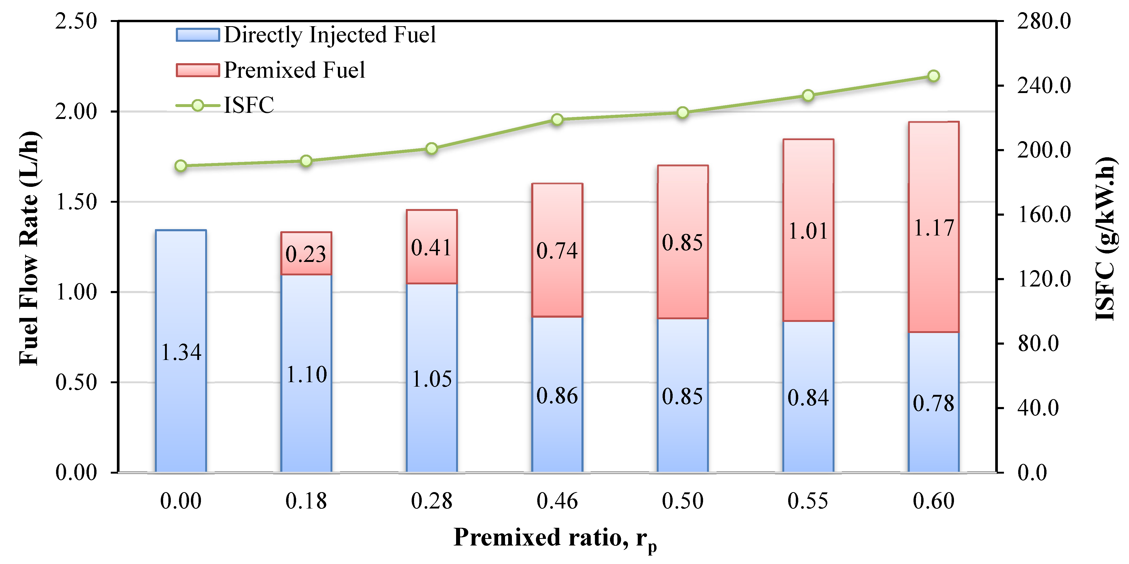
3.1.1. Engine Performance

Figure 3 shows the effects of premixed ratios (rp) on indicated specific fuel consumption (ISFC) and total fuel flow rate when the test engine was operated at 1600 rpm and 20 Nm load with intake air heated at 40 °C. It is noticeable from the figure that there was a slight decline in total fuel flow rate when a premixed ratio of 0.18 was used compared to fully direct-injected fuel. Subsequently, the total fuel flow rate raised along with an increment increase in the premixed ratio. The increase in total fuel flow rate with a higher premixed ratio may be attributable to the early combustion phasing of the premixed fuel as reported by Takeda et al. [30] and Nakagome et al. [31]. Therefore, higher fuel consumption was needed to acquire an equal amount of torque. In addition, the reductions in the directly injected fuel consumed were less significant at higher premixed ratios. It appears that the work-done achievable through the consumption of premixed fuel was restricted at raised premixed ratios. Furthermore, the ISFC shows an incremental trend with raised premixed ratios. This result is in good agreement with a study by Suzuki et al. [21] and Lee et al. [26] that recorded rises in ISFC with a high premixed fuel ratio. This could be explained by the built-up of cylinder pressure due to early combustion at the beginning that resists the upward movement of the piston. There might be opposite work done to the piston during the compression stroke which thus causes inefficiency for the following combustion near TDC, leading to penalties in ISFC. Additionally, the increase of unburned hydrocarbon (HC) with an increase in premixed ratio could also be related to the rise in ISFC. It appears that the use of higher premixed ratio fuel might not facilitate complete fuel combustion.

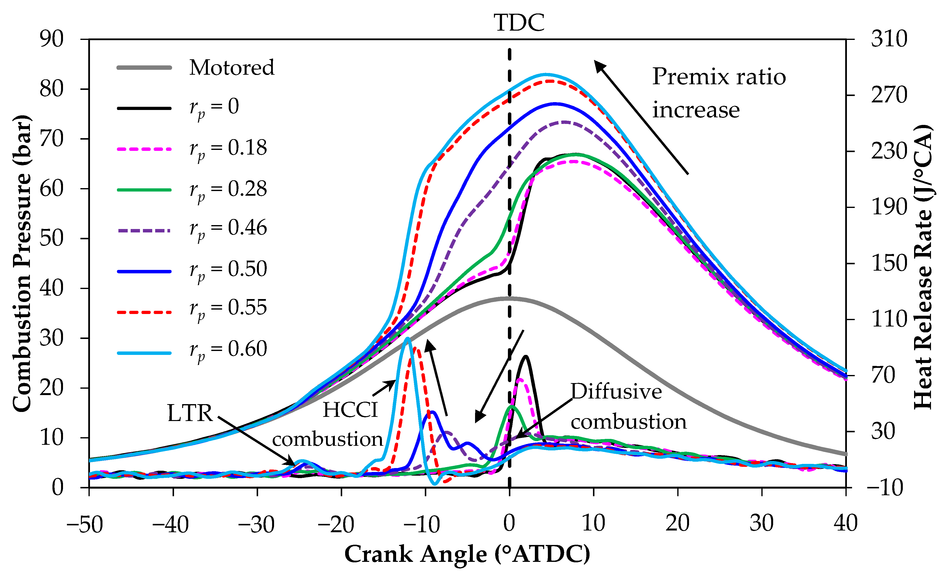
3.1.2. Combustion Characteristics

The cylinder pressure recorded and heat release rate determined with various premixed ratios are illustrated in Figure 4. Note that the motored cylinder pressure is depicted for ease of comparison. Overall, it is evident from Figure 4 that the peak pressures had tendencies to rise and shifted earlier towards TDC when the premixed ratio fuel was increased. This result is compatible with the study by Bhaskar et al. [32]; the authors observed a more advanced pressure rise with a higher peak for higher premixed ratios in a diesel engine with a modified injection system upstream of the intake manifold. Besides this, higher total fuel consumption at a higher premixed ratio leads to a richer mixture that may advance SOC and rate of heat release and cause greater cylinder pressure rise [13]. Furthermore, it is noticeable that the HRR profile and combustion pattern were dissimilar for lower (0.18 to 0.28) premixed ratios and higher (0.46 to 0.6) premixed ratios. Two-stage ignition occurred for the former while three-stage ignition happened for the latter. These phenomena are emphasized as being a chemical phenomenon where the thermal increase is hindered during the main ignition event. It is also noticeable that a higher HRR is associated with higher premixed ratios (0.46–0.60). This is due to more atomization of the premixed fuel in higher premixed ratios. The reason for this is that an increase of the premixed ratio increases the in-cylinder temperature to advance the auto-ignition of mixture in the cylinder, consequently prompting the combustion phase [33]. As described by Pekalski et al. [34], the first stage combustion corresponds to cool flame reactions and usually occurs at temperatures below the fuel auto-ignition temperature. In this stage, the ignition is triggered by the decomposition of highly oxygenated intermediates in low-temperature reactions. The production of olefins and HO2 radicals from RO2 prevents the low-temperature chemistry from proceeding to the thermal runaway. The details of the kinetic analysis of three-stage ignition explained by Sarathy et. al. [35,36] suggest that the first stage LTR is characterized by the same chemical pathways in both the fuel-lean and stoichiometric cases. From the experimental results, this reaction appears to occur consistently as small peaks of HRR near 27° BTDC. This phenomenon proved the LTR of the fuel since the peaks occurred at similar crank angle position despite varying premixed ratio.
Moreover, as depicted in Figure 4, the premixed fuel proportion demonstrated influences on the peak value and also the timing of HRR. The HRR peak was found to be lower and wider with lower premixed ratios of 0.18 to 0.46. However, it increased eventually and became narrower with a further increase in the premixed ratio. This may be attributed to a greater amount of heat released during the LTR stage with higher premixed ratios that consequently caused elevated in-cylinder temperature. This outcome might accelerate the overall kinetics and thus cause advancements in HCCI combustion timing [37]. The results in this work are in congruent with Lee et al.’s [26] study, which observed LTR around 20 °CA from TDC and a peak HRR that increased with more premixed fuel content in an HCCI diesel engine with PFI. A similar phenomenon was further explained by Sarathy et al. [36]; namely, that hydrogen-related oxidation dominates in the second stage which leads to thermal runaway in the case of stoichiometric mixtures. Highly reactive OH radicals are produced from the decomposition of H2O2, which promotes auto-ignition. This explains the elevated heat released with the increased premixed ratio.
The final stage of combustion recorded was the diffusion combustion of the directly injected fuel. In this stage, the HRR profile showed a reduction in width with higher premixed ratios, which is probably due to the smaller amount of directly injected fuel, as reported in Figure 3. Furthermore, as shown in Figure 5, the LTRs in this experiment commenced with modest reaction rates near 320 °C. This temperature limit is consistent with the findings reported by Pekalski et al. [34]. Three-stage ignition, initiated at 310 °C, was observed by the authors for the mixture of iso-butane and oxygen, along with in-cylinder temperature rises as a consequence of LTR heat release. Once the temperature achieved a value of approximately 460 °C, the HCCI combustion of the premixed fuel began by auto-ignition. Furthermore, this stage was dominated exclusively by hydrogen-related and CO-CO2 chemistry which explains the inhibition of CO oxidation.

3.1.3. Exhaust Emission Characteristics

Figure 6 illustrates the variations in smoke opacity, HC, CO and NO emissions with premixed ratios when 40 °C intake air was employed in an engine set at 1600 rpm and 20 Nm load. It is obvious that in broad terms, aggravations of HC, CO emissions and smoke opacity were recorded with combustions involving lower premixed fuel (up to 0.5). In fact, these engine emissions increased with a rising premixed ratio. Studies have shown rises in CO, HC and smoke opacity with partial HCCI systems [7,9,27,38]. This may be attributed to the lower combustion temperature of partial HCCI systems which induces partial oxidation of elements in fuel. According to findings by Sjöberg and Dec [39], the oxidation of CO emissions could not be completed with a peak temperature below 1500 K. On the other hand, a contrasting effect—the gradual decrease of NO emissions—could be observed with an increase in the premixed ratio up to a value of 0.5.
In particular, the reduction of NO emissions was recorded at a maximum of 14.5% for a premixed ratio of 0.5 compared to directly injected diesel combustion. With further increases in the premixed ratio, opposite trends were noticed for all emissions. For example, NO emission by the fuel was followed by a sharp increase from 165 ppm at rp = 0.50 to almost 210 ppm at rp = 0.60. Apparent improvements in CO and HC emissions and smoke capacity were also marked for a premixed ratio of more than 0.50. This phenomenon may be attributed to the occurrence of relatively more peaks in HRR across combustion stages for fuels with higher premixed fuel content. As a result, the combustion temperature may be elevated for further increased premixed ratio fuel, leading to the incremental trend of NO emissions; while declines for other measured emissions might be due to the more complete combustion achieved.

3.2. Effect of Intake Air Temperature

Intake air temperature (IAT) is a key factor affecting partial HCCI performance, combustion and emission. In this study, the idea of heating the intake air was intended to assist vaporization for fuel-mixing enhancement and also to reduce CO, HC and smoke emissions.

3.2.1. Engine Performance

Figure 7 demonstrates the total fuel flow rate and ISFC when a 1600 rpm, 20 Nm loaded engine was tested with varying intake temperatures and a premixed ratio set around 0.5. With the same output torque, it is apparent that the total fuel flow rate generally rises with an increase in IAT. As explained in the previous section, early combustion phasing of premixed fuel may be responsible for the growth in total fuel flow rate. Therefore, to achieve the same amount of output torque, a larger amount of fuel and thus a higher flow rate is needed for premixed fuel. In addition, the fuel flow rate was found to be significantly higher when the IAT was increased to 80 ℃ and beyond. Also, ISFC demonstrates an upward trend with rising intake temperature. This phenomenon may be due to LTR, which was observed to shift earlier with higher intake temperature as depicted in Figure 8. Early combustion, even at low temperature, may build up in-cylinder pressure that opposes the upward movement of the piston to TDC. Furthermore, an increase in intake temperature may lead to higher initial in-cylinder pressure prior to the compression stroke. Therefore, the drop in efficiency and higher ISFC in this study are a result of the coupled effects of a higher IAT.

3.2.2. Combustion Characteristics

Figure 8 shows the effect of IAT on partial HCCI combustion characteristics of premixed fuel around the premixed ratio of 0.5. In the illustration, the peak pressures increased with rising IAT. The occurrence of in-cylinder peak pressure was also noticed to shift earlier towards TDC with higher IAT. Furthermore, the pressure gradient achieved a significant increment with higher IAT. This result may be due to the earlier occurrence of LTR, which contributes to earlier pressure rise. In addition, the HRR profile determined from the in-cylinder pressure indicates distinctly that three-stage ignition occurred consistently for the fuel at any premixed ratio regardless of IAT. Moreover, it appears that the intake air heating had a greater effect than the premixed ratio on LTR and HCCI combustion timing.
In fact, the timing of both were largely advanced with increasing IAT. The findings are in good agreement with results obtained in a study by Lee et al. [26], who observed shifts of earlier peak HRR with higher IAT at a diesel premixed ratio of 0.5. Hasegawa et al.’s [7] study also showed an earlier peak HRR for the LTR stage when the intake gas temperature in a diesel-fuelled HCCI engine was increased. Besides this, it is noticeable that the peak rate of pressure rise was found to be 9.3 bar/°CA at an intake temperature of 100 °C, which exceeds the acceptable limit of 5 bar/°CA [40] or 6 bar/°CA [41] This reflects a limiting factor of the operational region for partial HCCI combustion due to excessive knocking, similar to what reported by Gowthaman et al. [10]. However, it is possible to minimise this issue. Cooled exhaust gas recirculation may be employed together with intake air heating to delay the timing of LTR by a dilution effect [17].

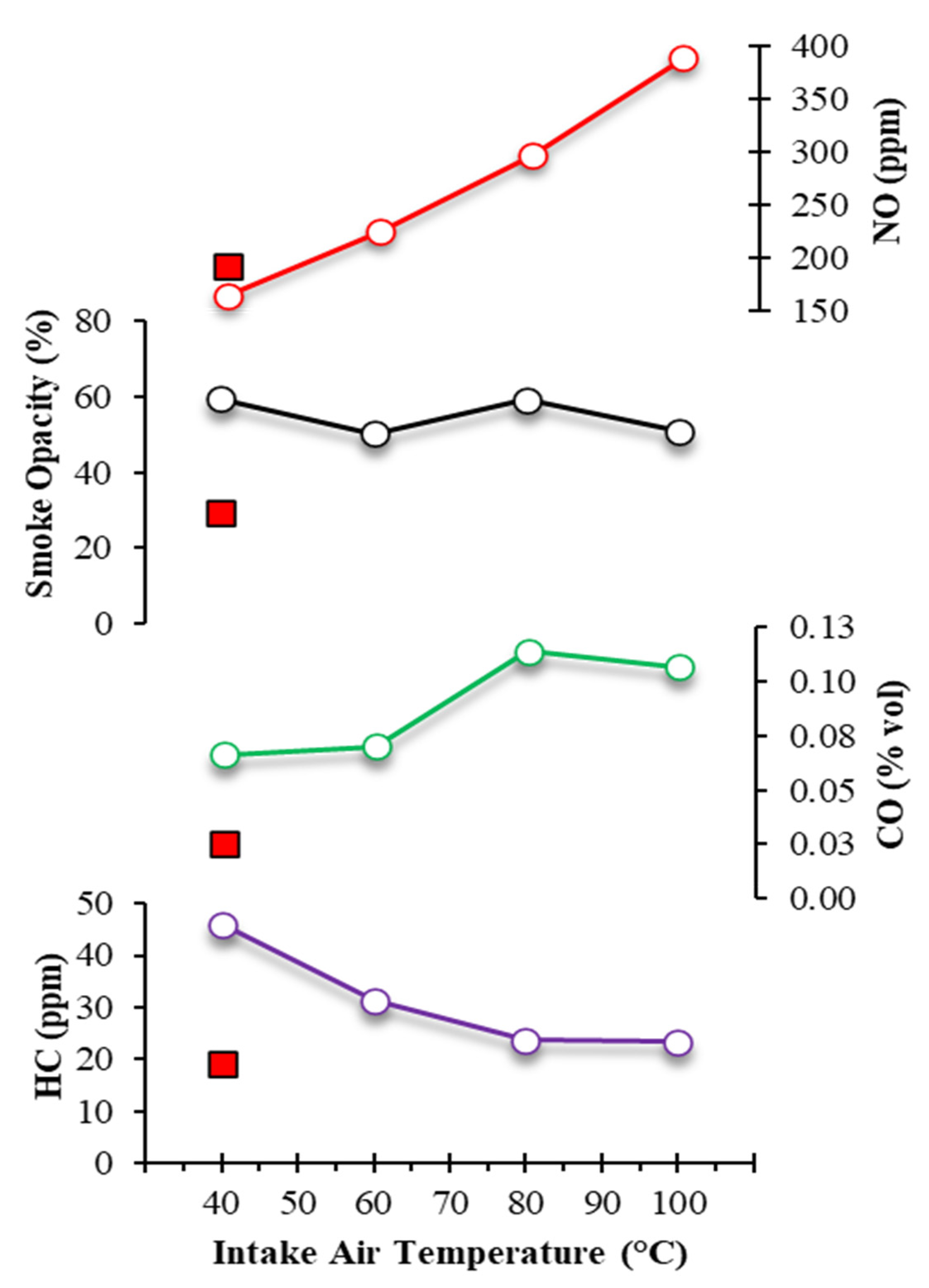
3.2.3. Exhaust Emission Characteristics

As shown in Figure 9, at the considerably high premixed ratio of approximately 0.5, an increase in inlet temperature provided improvement in HC emission but had adverse effects on CO and NO emissions. However, a less significant improvement in smoke opacity was also noticeable with intake air heating. Note that the square markers in the red, plotted on each of the diagrams, indicate the emission result for a premixed ratio of 0 and are displayed for comparison purposes. In this work, HC emission and smoke capacity demonstrated similar trends with intake temperature variations. At 40 °C, both showed improvement for the premixed ratio of 0.50 compared to when the engine was operated in conventional diesel mode. These results are incongruent with Gowthaman et al.’s findings [10]. The increase of IAT was also found to have adverse effects on CO emission and smoke opacity, which is probably due to the reduction of complete fuel combustion owing to the reduction of the intake airflow rate. As shown in Figure 7, the fuel flow rate for 80 °C and 100 °C intake air were significantly higher than other lower IATs. This rise in the fuel flow rate represents rapid fuel consumption, which might potentially reduce the fuel mixture quality and thus cause inferior combustion.
It is also evident from Figure 9 that HC emission was relatively high when the engine was run in conventional diesel mode at 40 °C. However, there was a dwindling trend in HC emissions with the heating of the intake air. This outcome is comparable to HC emission results by Gowthaman et al. [10] when using a port fuel injector at 5 bar in a diesel engine. In fact, the HC emission reduction demonstrated with air-assisted premixed FI at 7 bar in this study may be considered superior. This could provide proof such that both the wall wetting of premixed diesel fuel in the intake port and poor mixing issues might have been mitigated efficiently with the aid of air-assisted injection. Instead, a contrasting effect was found in NO emissions with the increase in IAT. NO emissions at a 0.5 premixed fuel ratio were lower than those with injected fuel at 40 °C. However, the amount of NO released rose more than twofold when IAT was increased to 100 °C. In fact, the increase in NO emissions exhibits an approximately linear relationship with the IAT. The observed phenomenon is possibly due to the rise in combustion temperature as a consequence of a higher chemical reaction rate with increased IAT. Higher combustion temperature tends to promote a thermal pathway that eases the production of Zeldovich NOx [42].

4. Conclusions

The investigations on combustion, performance and emissions traits utilising the partial HCCI combustion mode in a single-cylinder, water-cooled diesel engine was assessed successfully. The test engine was modified with an air-assisted FI system for improved pre-mixing of diesel fuel. From the findings, the following highlights can be derived:
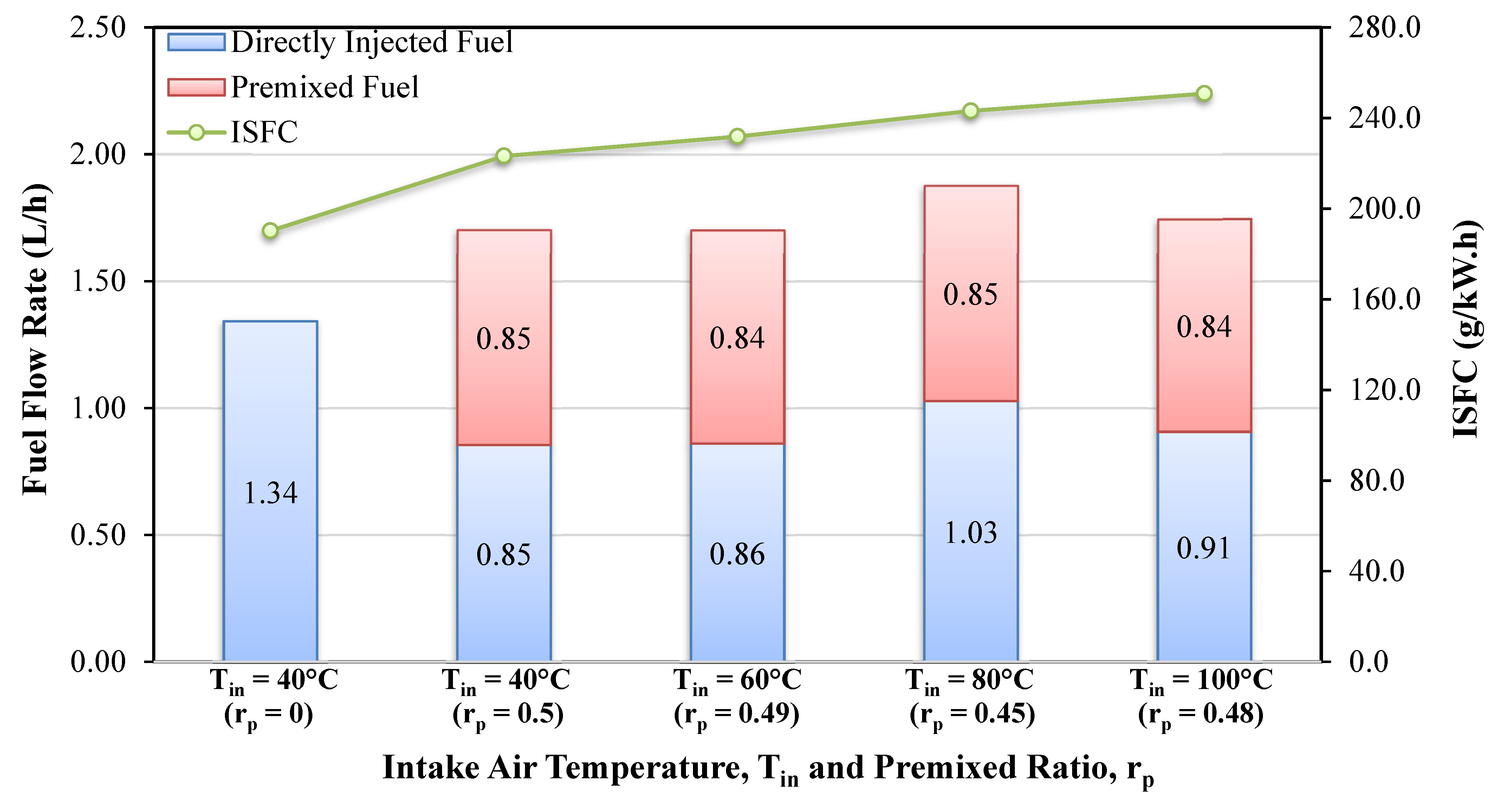
  • The ISFC and total fuel flow rate had an increasing trend with rises in premixed fuel proportion at a constant 40 °C IAT.
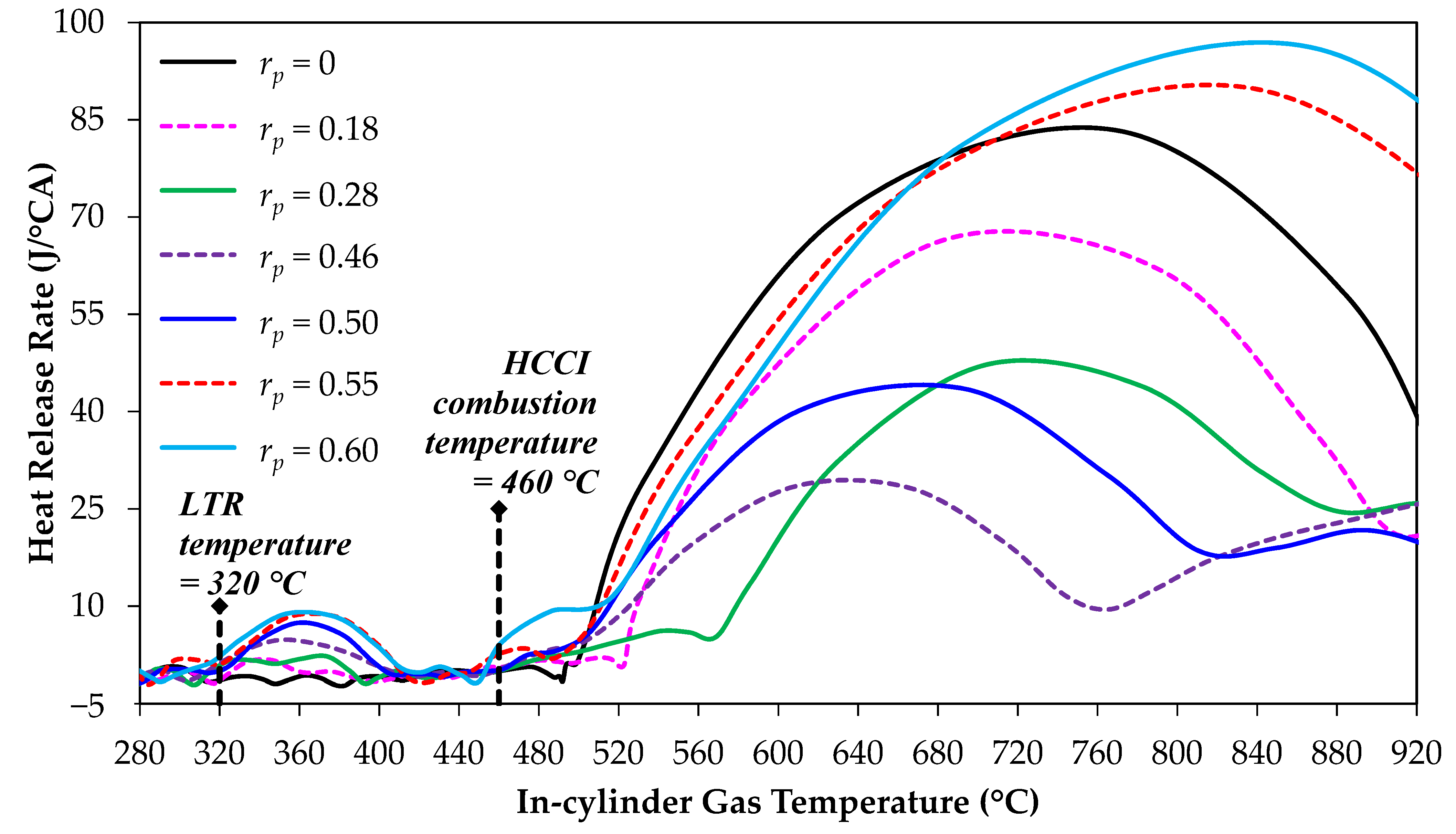
  • Multiple combustion stages were noticed in the partial HCCI engine fuelled with diesel. Two-stage combustion occurred for a lower premixed fuel ratio, while a higher premixed ratio setting resulted in three-stage ignition. Multiple combustion stages happen mainly due to the chemical reaction rate in different combustion stages. The premixed fuel ratio and the IAT affect the combustion characteristics.
  • With an increase in premixed fuel, significant advancement in SOC and pressure rise were noticed. The increased premixed ratio increased the in-cylinder temperature to advance the auto-ignition of the mixture in the cylinder.
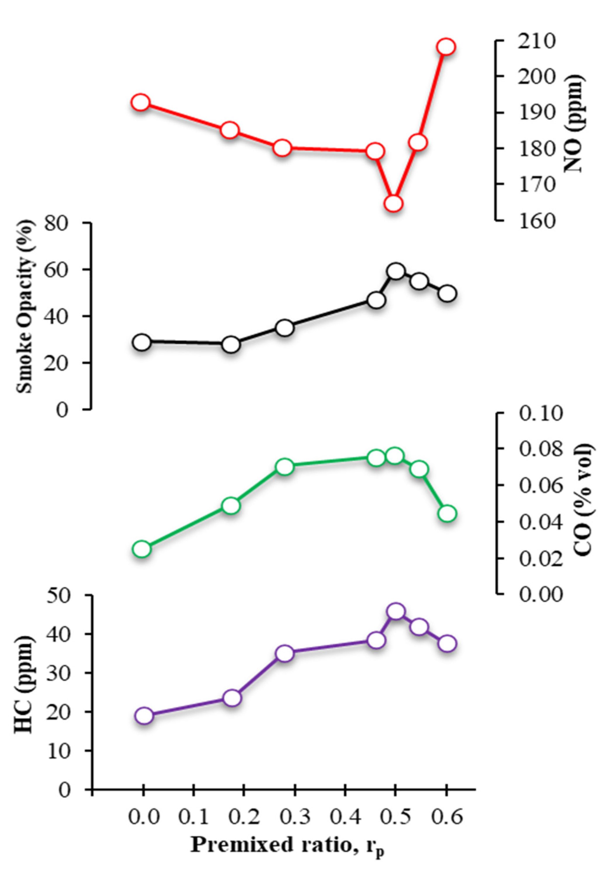
  • A greater quantity of HC and CO emissions and smoke opacity were found to occur when the premixed ratio was increased. In spite of worsened NO emission at high premixed ratios, the greatest NO reduction (14.5%) was achieved when half of the diesel fuel was premixed.
  • When the premixed ratio was controlled at approximately 0.50, the total fuel flow rate and ISFC were observed to rise with an increase in IAT.
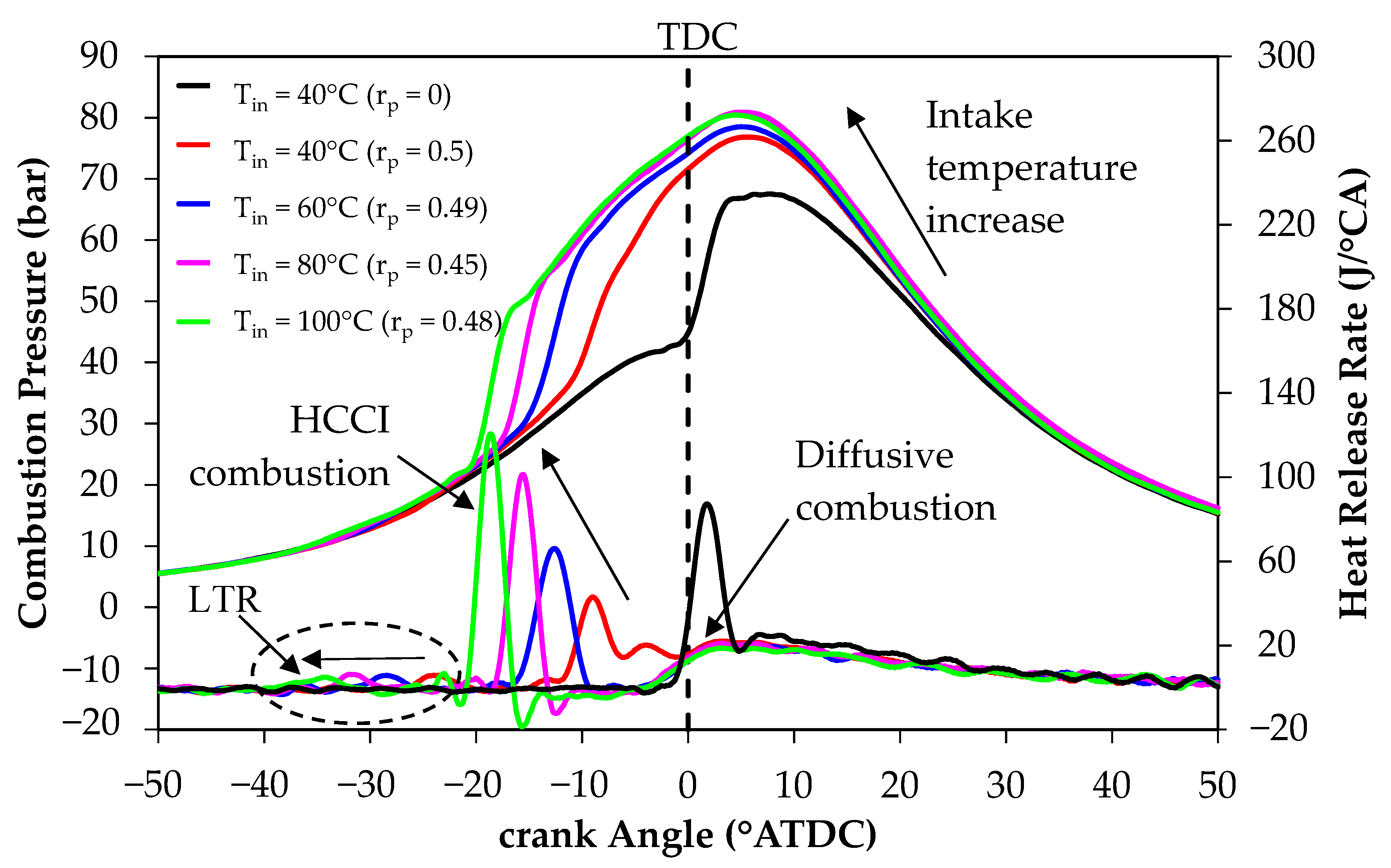
  • Compared to the premixed ratio, variations in inlet air temperature showed a greater effect on LTR and HCCI combustion timing which underwent very apparent earlier shifts. This phenomenon was due to a rise in combustion temperature as a consequence of a higher chemical reaction rate with the increased IAT.
  • At a premixed ratio of approximately 0.5, an increase in inlet temperature improved HC emission but also had an unfavourable effect such that higher CO and NO were released from the engine. Additionally, an insignificant improvement in smoke opacity was observed when intake air was heated to higher temperatures.
  • Consequently, controlling the premixed ratio and IAT on a partial HCCI may have a great potential to control the auto-ignition. Besides this, more work needs to be done to improve emissions.

Author Contributions

Conceptualization, Y.H.T. and H.A.H.; Data curation, Y.H.T. and H.A.H.; Formal analysis, Y.H.T.; Funding acquisition, Y.H.T., F.S. and H.G.H.; Investigation, H.G.H. and H.A.H.; Methodology, H.G.H. and H.A.H.; Project administration, Y.H.T. and F.S.; Resources, Y.H.T. and H.G.H.; Software, H.G.H., Z.U.D. and T.D.L.; Supervision, Y.H.T.; Validation, Y.H.T. and Z.U.D.; Visualization, T.D.L., F.S. and H.T.N.; Writing—original draft, Y.H.T. and H.G.H.; Writing—review and editing, F.S. and H.T.N. All authors have read and agreed to the published version of the manuscript.

Funding

This study was supported by the Ministry of Higher Education of Malaysia and Universiti Sains Malaysia (USM) through the Fundamental Research Grant Scheme (FRGS)- 203.PMEKANIK.6071444 (Title: Mechanism Study of Combustion and Formulation of Surrogate Biomass Producer Gas Using a CVCC System) and Universiti Sains Malaysia Research University (RUI) Grant Scheme- 1001.PMEKANIK.8014136 (Title: Effect of Fuel Injection Strategies and Intake Air Supply Control on Performance, Emissions, and Combustion Characteristics of Diesel Engine Fueled with Biodiesel Blended Fuels).

Institutional Review Board Statement

Not applicable.

Informed Consent Statement

Not applicable.

Data Availability Statement

Not applicable.

Conflicts of Interest

The authors declare that they have no known competing financial interests or personal relationships that could have appeared to influence the work reported in this paper.

References

  1. Yasin, M.H.; Mamat, R.; Najafi, G.; Ali, O.M.; Yusop, A.F.; Ali, M.H. Potentials of palm oil as new feedstock oil for a global alternative fuel: A review. Renew. Sustain. Energy Rev. 2017, 79, 1034–1049. [Google Scholar] [CrossRef] [Green Version]
  2. Agarwal, A.K.; Singh, A.P.; Maurya, R.K. Evolution, challenges and path forward for low temperature combustion engines. Prog. Energy Combust. Sci. 2017, 61, 1–56. [Google Scholar] [CrossRef]
  3. Onishi, S.; Jo, S.H.; Shoda, K.; Jo, P.D.; Kato, S. Active Thermo-Atmosphere Combustion (ATAC)—A New Combustion Process for Internal Combustion Engines; SAE International: Warrendale, PA, USA, 1979. [Google Scholar]
  4. Urushihara, T.; Hiraya, K.; Kakuhou, A.; Itoh, T. Expansion of HCCI Operating Region by the Combination of Direct Fuel Injection, Negative Valve Overlap and Internal Fuel Reformation; SAE International: Warrendale, PA, USA, 2003. [Google Scholar]
  5. Gomes Antunes, J.M.; Mikalsen, R.; Roskilly, A.P. An Investigation of Hydrogen-Fuelled HCCI Engine Performance and Operation. Int. J. Hydrogen Energy 2008, 33, 5823–5828. [Google Scholar] [CrossRef] [Green Version]
  6. Azad, A.K.; Rasul, M.G.; Khan, M.M.; Sharma, S.C.; Bhuiya, M.M. Recent development of biodiesel combustion strategies and modelling for compression ignition engines. Renew. Sustain. Energy Rev. 2016, 56, 1068–1086. [Google Scholar] [CrossRef]
  7. Hasegawa, R.; Yanagihara, H. HCCI Combustion in DI Diesel Engine; SAE International: Warrendale, PA, USA, 2003. [Google Scholar]
  8. Juttu, S.; Thipse, S.S.; Marathe, N.V.; Babu, M.G. Homogeneous Charge Compression Ignition (HCCI): A New Concept for Near Zero NOx and Particulate Matter (PM) from Diesel Engine Combustion; The Automotive Research Association of India: Maharashtra, India, 2007. [Google Scholar]
  9. Hasan, M.M.; Rahman, M.M. Homogeneous charge compression ignition combustion: Advantages over compression ignition combustion, challenges and solutions. Renew. Sustain. Energy Rev. 2016, 57, 282–291. [Google Scholar] [CrossRef] [Green Version]
  10. Gowthaman, S.; Sathiyagnanam, A.P. Effects of charge temperature and fuel injection pressure on HCCI engine. Alex. Eng. J. 2016, 55, 119–125. [Google Scholar] [CrossRef] [Green Version]
  11. Zhao, F.; Asmus, T.N.; Assanis, D.N.; Dec, J.E.; Eng, J.A.; Najt, P.M. Homogeneous Charge Compression Ignition (HCCI) Engines—Key Research and Development Issues; SAE International: Warrendale, PA, USA, 2003. [Google Scholar]
  12. Szybist, J.P.; Bunting, B.G. Cetane Number and Engine Speed Effects on Diesel HCCI Performance and Emissions; SAE International: Warrendale, PA, USA, 2005. [Google Scholar]
  13. Singh, A.P.; Agarwal, A.K. Combustion characteristics of diesel HCCI engine: An experimental investigation using external mixture formation technique. Appl. Energy 2012, 99, 116–125. [Google Scholar] [CrossRef]
  14. Hairuddin, A.A.; Yusaf, T.; Wandel, A.P. A review of hydrogen and natural gas addition in diesel HCCI engines. Renew. Sustain. Energy Rev. 2014, 32, 739–761. [Google Scholar] [CrossRef] [Green Version]
  15. Bendu, H.; Murugan, S. Homogeneous charge compression ignition (HCCI) combustion: Mixture preparation and control strategies in diesel engines. Renew. Sustain. Energy Rev. 2014, 38, 732–746. [Google Scholar] [CrossRef]
  16. Gray, A.W.; Ryan, T.W. Homogeneous Charge Compression Ignition (HCCI) of Diesel Fuel; SAE International: Warrendale, PA, USA, 1997. [Google Scholar]
  17. Kim, D.S.; Lee, C.S. Improved emission characteristics of HCCI engine by various premixed fuels and cooled EGR. Fuel 2006, 85, 695–704. [Google Scholar] [CrossRef]
  18. Kumar, P.; Rehman, A. Bio-diesel in homogeneous charge compression ignition (HCCI) combustion. Renewable and Sustain. Energy Rev. 2016, 56, 536–550. [Google Scholar] [CrossRef]
  19. Pandey, S.; Diwan, P.; Sahoo, P.K.; Thipse, S.S. A review of combustion control strategies in diesel HCCI engines. Biofuels 2018, 9, 61–74. [Google Scholar] [CrossRef]
  20. Saravanan, S.; Pitchandi, K.; Suresh, G. An experimental study on premixed charge compression ignition-direct ignition engine fueled with ethanol and gasohol. Alex. Eng. J. 2015, 54, 897–904. [Google Scholar] [CrossRef] [Green Version]
  21. Suzuki, H.; Koike, N.; Odaka, M. Combustion Control Method of Homogeneous Charge Diesel Engines; SAE International: Warrendale, PA, USA, 1998. [Google Scholar]
  22. Ying, W.; Li, H.; Jie, Z.; Longbao, Z. Study of HCCI-DI combustion and emissions in a DME engine. Fuel 2009, 88, 2255–2261. [Google Scholar] [CrossRef]
  23. Ma, J.; Lü, X.; Ji, L.; Huang, Z. An experimental study of HCCI-DI combustion and emissions in a diesel engine with dual fuel. Int. J. Therm. Sci. 2008, 47, 1235–1242. [Google Scholar] [CrossRef]
  24. Yao, M.; Zheng, Z.; Liu, H. Progress and recent trends in homogeneous charge compression ignition (HCCI) engines. Prog. Energy Combust. Sci. 2009, 35, 398–437. [Google Scholar] [CrossRef]
  25. Ganesh, D.; Nagarajan, G. Homogeneous charge compression ignition (HCCI) combustion of diesel fuel with external mixture formation. Energy 2010, 35, 148–157. [Google Scholar] [CrossRef]
  26. Lee, C.S.; Lee, K.H.; Kim, D.S. Effect of Premixed Ratio on Nitric Oxide Emission in Diesel Engine; SAE International: Warrendale, PA, USA, 2001. [Google Scholar]
  27. Kim, D.S.; Kim, M.Y.; Lee, C.S. Combustion and Emission Characteristics of Partial Homogeneous Charge Compression Ignition Engine. Combust. Sci. Technol. 2004, 177, 107–125. [Google Scholar] [CrossRef]
  28. Houston, R.; Cathcart, G. Combustion and Emissions Characteristics of Orbital’s Combustion Process Applied to Multi-Cylinder Automotive Direct Injected 4-Stroke Engines; SAE International: Warrendale, PA, USA, 1998. [Google Scholar]
  29. Koci, C.; Florea, R.; Das, S.; Walls, M.; Simescu, S.; Roberts, C. Air-Assisted Direct Injection Diesel Investigations; SAE International: Warrendale, PA, USA, 2013. [Google Scholar]
  30. Takeda, Y.; Keiichi, N.; Keiichi, N. Emission Characteristics of Premixed Lean Diesel Combustion with Extremely Early Staged Fuel Injection; SAE International: Warrendale, PA, USA, 1996. [Google Scholar]
  31. Nakagome, K.; Shimazaki, N.; Niimura, K.; Kobayashi, S. Combustion and Emission Characteristics of Premixed Lean Diesel Combustion Engine; SAE International: Warrendale, PA, USA, 1997. [Google Scholar]
  32. Bhaskar, K.; Nagarajan, G.; Sampath, S. The Effects of Premixed Ratios on the Performance and Emission of PPCCI Combustion in a Single Cylinder Diesel Engine. Int. J. Green Energy 2013, 10, 1–11. [Google Scholar] [CrossRef]
  33. Tingas, E.A.; Wang, Z.; Sarathy, S.M.; Im, H.G.; Goussis, D.A. Chem. Kinet. Insights Into Ignition Dyn. N-Hexane. Combust. Flame 2018, 188, 28–40. [Google Scholar]
  34. Pekalski, A.A.; Zevenbergen, J.F.; Pasman, H.J.; Lemkowitz, S.M.; Dahoe, A.E.; Scarlett, B. The relation of cool flames and auto-ignition phenomena to process safety at elevated pressure and temperature. J. Hazard. Mater. 2002, 93, 93–105. [Google Scholar] [CrossRef]
  35. Houidi, M.B.; AlRamadan, A.S.; Sotton, J.; Bellenoue, M.; Sarathy, S.M.; Johansson, B. Understanding multi-stage HCCI combustion caused by thermal stratification and chemical three-stage auto-ignition. Proc. Combust. Inst. 2021, 38, 5575–5583. [Google Scholar] [CrossRef]
  36. Sarathy, S.M.; Tingas, E.A.; Nasir, E.F.; Detogni, A.; Wang, Z.; Farooq, A.; Im, H. Three-stage heat release in n-heptane auto-ignition. Proc. Combust. Inst. 2019, 37, 485–492. [Google Scholar] [CrossRef]
  37. Machrafi, H.; Cavadias, S.; Gilbert, P. An experimental and numerical analysis of the HCCI auto-ignition process of primary reference fuels, toluene reference fuels and diesel fuel in an engine, varying the engine parameters. Fuel Process. Technol. 2008, 89, 1007–1016. [Google Scholar] [CrossRef] [Green Version]
  38. Zaidi, K.; Andrews, G.E.; Greenhaugh, J.H. Effect of Partial Fumigation of the Intake Air with Fuel on a DI Diesel Engine Emissions; SAE International: Warrendale, PA, USA, 2002. [Google Scholar]
  39. Sjöberg, M.; Dec, J.E. An investigation into lowest acceptable combustion temperatures for hydrocarbon fuels in HCCI engines. Proc. Combust. Inst. 2005, 30, 2719–2726. [Google Scholar] [CrossRef]
  40. Kamio, J.; Kurotani, T.; Kuzuoka, K.; Kubo, Y.; Taniguchi, H.; Hashimoto, K. Study on HCCI-SI Combustion Using Fuels Containing Ethanol; SAE Transactions: Warrendale, PA, USA, 2007. [Google Scholar]
  41. Sun, R.; Thomas, R.; Gray, C.L. An HCCI Engine: Power Plant for a Hybrid Vehicle; SAE International: Warrendale, PA, USA, 2004. [Google Scholar]
  42. Brakora, J.L.; Reitz, R.D. Investigation of NOx Predictions from Biodiesel-Fueled HCCI Engine Simulations Using a Reduced Kinetic Mechanism; SAE International: Warrendale, PA, USA, 2010. [Google Scholar]
Figure 1. Schematic diagram of the experimental setup.
Sustainability 13 08593 g001
Figure 2. Fuel vaporiser plume in a 2 L flask at room temperature.
Sustainability 13 08593 g002
Figure 3. Indicated specific fuel consumption (ISFC) and total fuel flow rate for various premixed ratios, rp at 1600 rpm, 20 Nm and Tin = 40 °C.
Sustainability 13 08593 g003
Figure 4. Effect of premixed ratio on heat release rate profile and combustion pressure at 1600 rpm, 20 Nm and Tin = 40 °C.
Sustainability 13 08593 g004
Figure 5. Heat release rate as a function of in-cylinder gas temperature for various premixed ratio at 1600 rpm, 20 Nm and Tin = 40 °C.
Sustainability 13 08593 g005
Figure 6. Effect of premixed ratio on HC, CO and NO emissions and smoke opacity at 1600 rpm, 20 Nm and Tin = 40 °C.
Sustainability 13 08593 g006
Figure 7. Indicated specific fuel consumption (ISFC) and total fuel flow rate for various intake temperatures, Tin at 1600 rpm, 20 Nm and premixed ratio of around 0.5.
Sustainability 13 08593 g007
Figure 8. Effect of intake air temperature on heat release rate and combustion pressure at 1600 rpm, 20 Nm and premixed ratio of around 0.5.
Sustainability 13 08593 g008
Figure 9. Effect of intake air temperature on CO, HC and NO emissions and smoke opacity at 1600 rpm, 20 Nm and premixed ratio of around 0.5.
Sustainability 13 08593 g009
Table 1. Engine specifications used in the experiments.
Engine ModelSingle-Cylinder Water-Cooled 4-Stroke DI Diesel
Bore (mm)92
Stroke (mm)96
Displacement (cm3)638
Compression ratio17.7:1
Continuous rating output (rpm)7.8 kW @ 2400
One-hour rating output (rpm)8.9 kW @ 2400
Injection timing (°BTDC)17
Injection pressure (bar or kg/cm2)
Connecting rod length
196 or 200
149.5 mm
Connecting rod length (mm)149.50
Table 2. Fuel properties of diesel fuel.
PropertiesTest MethodSpecification
Cetane indexASTM D976>52
Flash pointASTM D9371.5 °C
Density @ 40 °CASTM D7042838.4 kg/m3
Kinematic viscosity @ 40 °CASTM D70423.815 mm2/s
Heating valueASTM D480945.31 MJ/kg
Table 3. Experimental test conditions.
Engine Speed 1600 rpm
Engine load 20 Nm
Intake air temperature 40–100 °C
FuelPremixedDiesel
Directly injectedDiesel
Injection pressurePremixed700 kPa
Directly injected19,600 kPa
Injection timingPremixed47 °ABDC
Directly injected17 °BTDC
Premixed ratio, rp 0–0.6
Publisher’s Note: MDPI stays neutral with regard to jurisdictional claims in published maps and institutional affiliations.

