
A Novel Oil-free Dual Piston Compressor Driven by a Moving Coil Linear Motor with Capacity Regulation Using R134a

1
Key Laboratory of Technology on Space Energy Conversion, Technical Institute of Physics and Chemistry, Chinese Academy of Science, Beijing 100190, China
2
University of Chinese Academy of Sciences, Beijing 100190, China
*
Author to whom correspondence should be addressed.
Sustainability 2021, 13(9), 5029; https://doi.org/10.3390/su13095029
Submission received: 3 March 2021
/
Revised: 19 March 2021
/
Accepted: 23 March 2021
/
Published: 30 April 2021
(This article belongs to the Special Issue Sustainable and Renewable Energy Technologies in the Built Environment)
Abstract
:Improving compressor efficiency is very important to save energy and reduce greenhouse gas emissions. A novel oil-free dual piston compressor prototype driven by a moving coil linear motor was developed, and its working principle was described in detail. The prototype was integrated with a test rig to measure the operation characteristics, the compressor efficiencies and the coefficient of performance (COP). The results show that the dual piston structure results in extraordinary sinusoidal gas force and electromagnetic force and significantly reduces piston offset, which is completely different from the traditional single piston structure. Compared with the variable frequency method, the variable stroke method has lower energy consumption and a higher COP, which is more suitable to cooling capacity regulation for the prototype. The maximum COP, motor efficiency and volumetric efficiency are 5.34, 87.9% and 79.1%, respectively, under the design condition (the evaporation pressure is 0.35 MPa, and the pressure ratio is 2.54). The COP of the linear compressor is 38%, 24% and 12% higher than the commercial crank-driven reciprocating compressor at the pressure ratios of 2.54, 2.80 and 3.90, respectively, which reflects the efficiency advantage of the dual piston linear compressor in household refrigeration.
1. Introduction
The rapidly increasing refrigeration equipment in buildings leads to a dramatic increase in energy consumption and greenhouse gas emissions, which exacerbates the greenhouse effect [1]. In Europe, refrigeration and heating equipment accounts for about 40% of electricity consumption [2]. In China, air conditioning consumes approximately 47% of operational energy consumption in buildings [3,4]. As the heart of refrigeration equipment, improving the compressor efficiency is the focus of energy saving and emission reduction. Different from the traditional crank-driven reciprocating compressor, a linear compressor has no low-efficiency and complex crank connecting rod mechanism, and the piston is directly connected with the linear motor. The springs with large radial or axial stiffness ratios make the piston and cylinder coaxial, which eliminates or reduces the dry friction and realizes oil-free or low-oil operation [5,6]. Based on the above advantages, linear compressors without a suction valve and a discharge valve have been widely used as pressure wave generators for Stirling cryocoolers, pulse tube cryocoolers and Gifford-McMahon cryocoolers for many years, and the linear compressor with valves can be used for air compressors, Joule–Thomson throttling cryocoolers and vapor compression refrigeration (VCR) systems in order to improve the pressure and deliver the mass flow of the working fluid [7,8]. The VCR systems driven by linear compressors have many advantages, such as being oil-free, having high efficiency, easy cooling capacity regulation and long service life, and they can be applied to electronic cooling, household refrigerators and air conditioners [8,9]. Kun et al. [10] concluded that oil-free operation allowed the use of high-efficiency microchannel heat exchangers and broadened the selection range and operating temperature range of refrigerants. Bradshaw et al. [11,12] developed a compressor model and demonstrated that linear compressors were more efficient than crank-driven compressors over a large range of clearance volumes. Park et al. [13] experimentally demonstrated that the efficiency of the linear compressor was 20–30% higher than the reciprocating compressor with a rotating induction motor. Kun et al. [14] experimentally concluded that the linear motor efficiency was much higher than a conventional induction motor using N2, especially at low power inputs. Bansal et al. [15] reviewed the development of household appliances and pointed out that linear compressors provided a more efficient and promising alternative to regulate the cooling capacity.
The application of single-piston linear compressors in household refrigeration has been adequately studied. Unger et al. [16] tested the refrigeration performance of a SunPower-type linear compressor using R600a. The results showed the cooling capacity reaching 40 W and the coefficient of performance (COP) being 2.5 at 50 Hz under freezer conditions (i.e., −18 °C), and the cooling capacity reached 120 W with the coefficient of performance (COP) being 3 under fresh food conditions (i.e., 4 °C). LG Electronics has commercialized moving magnetic linear compressors with lubricating oil since 2002 [17]. Bradshaw [18] measured the performance of LG linear compressors in refrigerators. The results showed that the COP was 1.34 with a cooling capacity of 150 W and an isentropic efficiency of 65% when the evaporator temperature was −5 °C. Zou at al. [19] developed and assembled a moving magnetic linear compressor with oil for refrigerators. The COP reached 1.97 with a cooling capacity of 672 W using R290 when the condensation temperature was 54.4 °C, the evaporation temperature was −23.3 °C and the COP was 2.09 using R600a in the same conditions. Embraco has commercialized oil-free linear compressors with gas bearings since 2014. High efficiency of the linear compressor was claimed, but few studies in the literature proved it [20,21]. Jomde et al. [22] developed and assembled an oil-free moving coil linear compressor prototype. The refrigeration capacity reached 134 W, and the COP was 1.4 when the evaporation temperature was 20 °C and the condensation temperature was 54 °C; the COP reached 2.13 with a cooling capacity of 325 W when the evaporation temperature was 2 °C. Lee et al. [23] tested the performance of the LG type compressor using R410A under ASHRAE-T conditions (evaporation temperature of 7.2 °C and condensation temperature of 54.4 °C). The experimental results showed that the maximum COP was 3.66 with a cooling capacity of 3500 W and a motor efficiency of 92%. However, Liang [8] pointed out that the large stiffness springs for reducing the piston offset resulted in the increase in volume and weight of the LG-type linear compressors and made them lose the advantages of volume and weight in large cooling capacity refrigeration. It can be seen that the research on linear compressors for refrigerators is very rich, but the research on linear compressors for air conditioners is very limited.
Compared with single-piston linear compressors, research on dual-piston linear compressors is very scarce. Herrmann [24] proposed a dual acting compressor driven by a moving coil linear motor in 1954. Zou [25] developed and assembled a dual-piston linear compressor driven by a moving magnetic linear motor with oil for refrigerators in 2010. The performance of the dual-piston linear compressor under variable working conditions was simulated by a Maxwell and Simplorer workbench, and the control strategy of the linear compressor was also studied based on the simulation workbench. The performance study of the prototype showed that the COP was 1.28 with a cooling capacity of 123.6 W while using R600a when the condensation temperature was 54.4 °C and the evaporation temperature was −23.3 °C. Zou et al. [25,26] established a dynamic compressor model and investigated the operating characteristics of the compressor under different spring stiffnesses using air. The results showed that the working conditions and the spring stiffness had a significant impact on the compressor performance. The driving frequency should be less than the resonance frequency of the compressor to ensure stable operation and high efficiency. Wei et al. [27] developed a numerical model including the piston dynamics, gas thermodynamics and electromagnetics of the dual-piston linear compressor by the Matlab/Simulink workbench. The compressor performance under five typical piston displacement waveforms was simulated. The results showed that the triangle displacement waveform had the highest compression efficiency and electrical efficiency. To sum up, the research on dual-piston linear compressors is mainly theoretical research, and there is a lack of refrigeration experimental verification.
From the above literature, it can be seen that the research on linear compressors for air conditioning is very scarce, and the experimental research on dual-piston linear compressors for air conditioning is scarcer. Compared with the single-piston linear compressor, the dual-piston linear compressor has a more complex structure and greater assembly difficulty, but the dual-piston linear compressor may have higher efficiency and special advantages, so it is especially necessary to carry out research on the dual-piston linear compressor. An oil-free dual-piston compressor driven by a moving coil linear motor is developed in this work. The operating principle of the piston is described in detail, and the current, gas force and electromagnetic force waveform at resonance are measured and analyzed. The compressor efficiency (power factor, motor efficiency, volumetric efficiency and isentropic efficiency) and system performance (cooling capacity, COP and the normalized COP) under the two cooling capacity regulation methods of variable stroke and variable frequency under the design conditions are compared experimentally, and the cooling capacity regulation strategy of the dual-piston linear compressor is obtained. Finally, the performance of the dual-piston linear compressor is compared with the traditional crank-driven compressor. This work can provide guidance for the application of the dual-piston linear compressor in household refrigeration.
2. Test Setup
2.1. Dual-Piston Linear Compressor
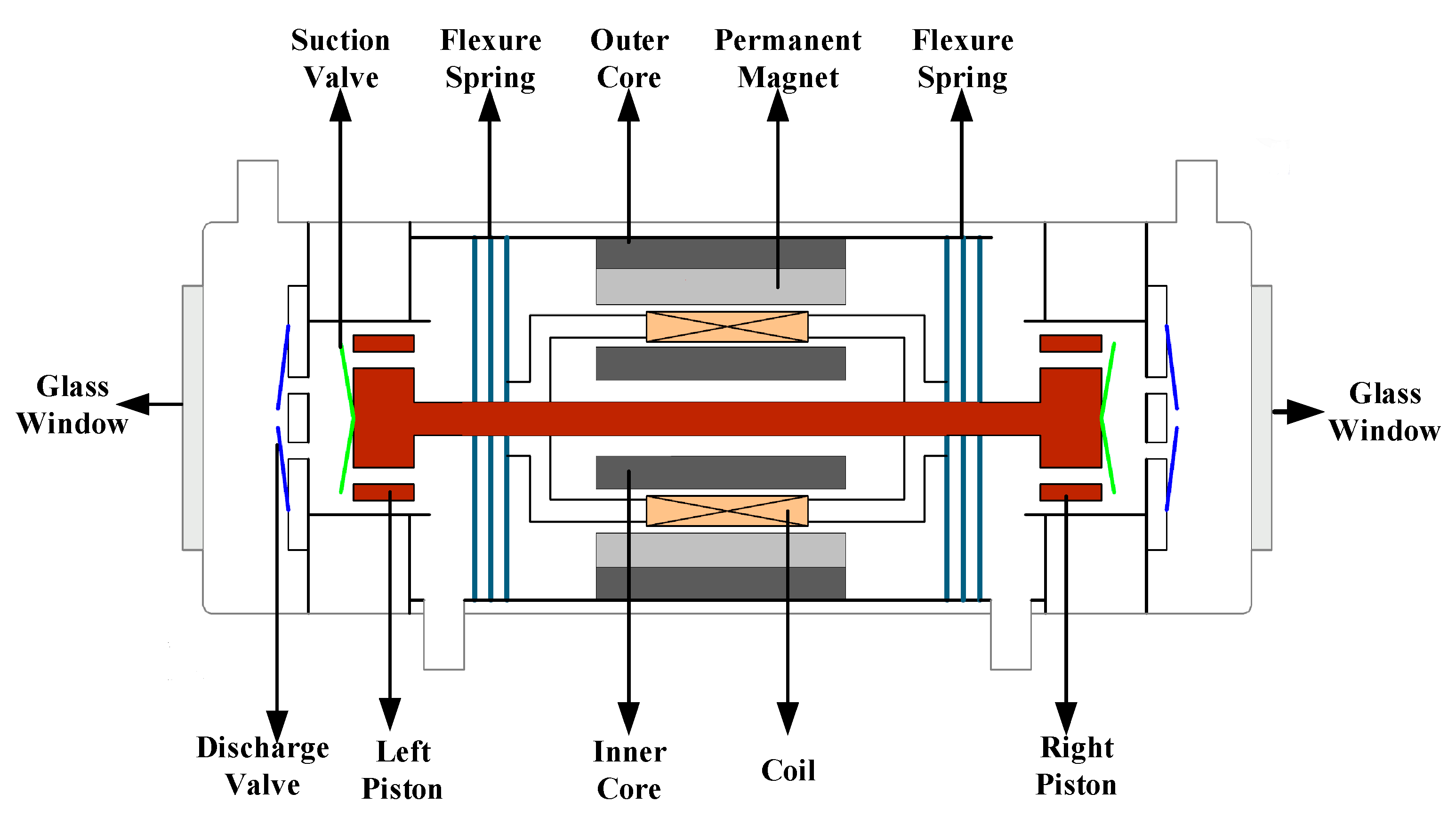
An oil-free dual-piston compressor driven by a moving coil linear compressor was developed and assembled for household refrigeration. Figure 1 shows a schematic diagram of the linear compressor. It mainly included a moving coil linear motor, a flexure support system and two gas compression systems. The moving coil linear motor adopted a radial magnetization structure, and the permanent magnet was made of NdFeB. The flexure support system comprised ten flexure springs, which were fixed on both sides of the motor to maintain the coaxiality between the piston and the cylinder and reduce the dry friction. The gas compression system consisted of a piston hollowed out as the suction channel, a cylinder, a ring reed suction valve, a reed discharge valve and a valve plate. The valve plate was made of PEEK (polyether-ether-ketone) with low thermal conductivity to reduce heat transfer from the discharge chamber to the compression chamber.
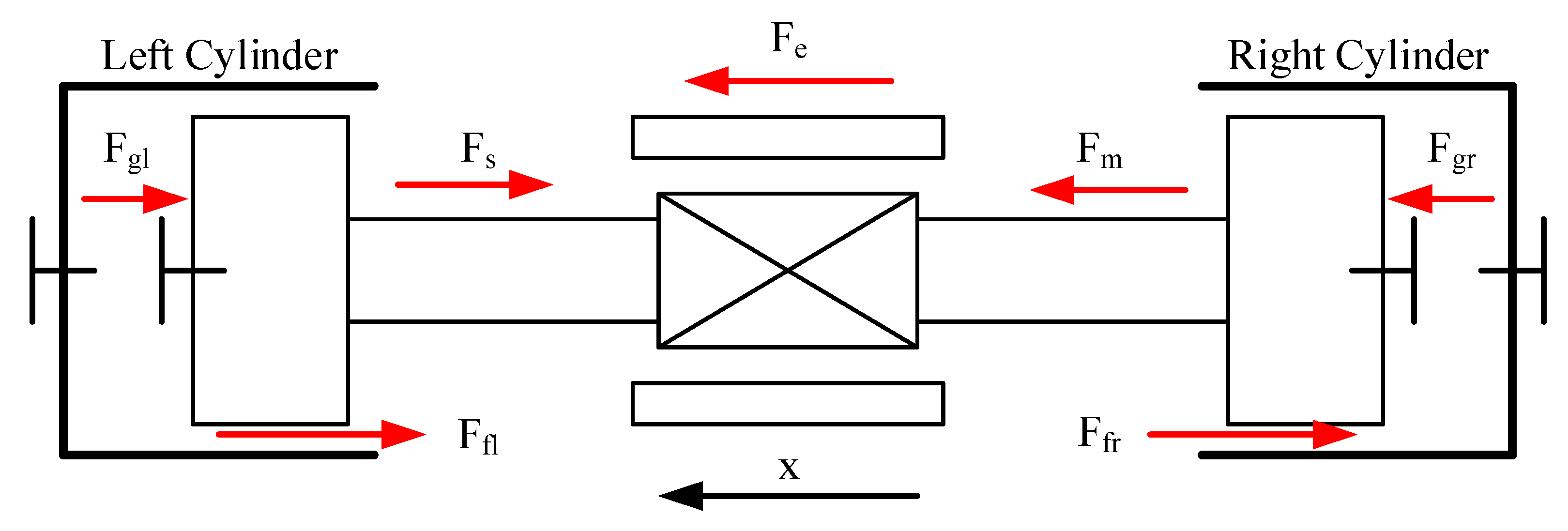
The forces acting on the dual piston assembly are shown in Figure 2. The piston assembly was subjected to an electromagnetic force (), mechanical spring force (), inertia force (), damping force () and gas forces acting on the two cylinders (). It is worth noting that the gas force on the left piston was always opposite that on the right piston, which was the significant difference between the dual-piston linear compressor and the single-piston linear compressor. According to Newton’s second law, the force balance equation can be obtained as follows:
where is the moving mass (kg), is the equivalent damping coefficient (N•s/m), is the mechanical spring coefficient (N/m), is the gas force acting on the dual piston (N), is the motor coefficient (N/A), is the driving current (A), is the piston displacement (m) and is the time (s).
When the linear compressor was connected with alternating current, the two pistons oscillated in a straight line driven by electromagnetic force, and the refrigerant gas was compressed, discharged, expanded and suctioned in turn under the cooperation of the suction valve and the discharge valve. The working process illustration with the displacement direction is shown in Table 1. The design parameters of the dual-piston linear compressor are displayed in Table 2.
2.2. Test Rig
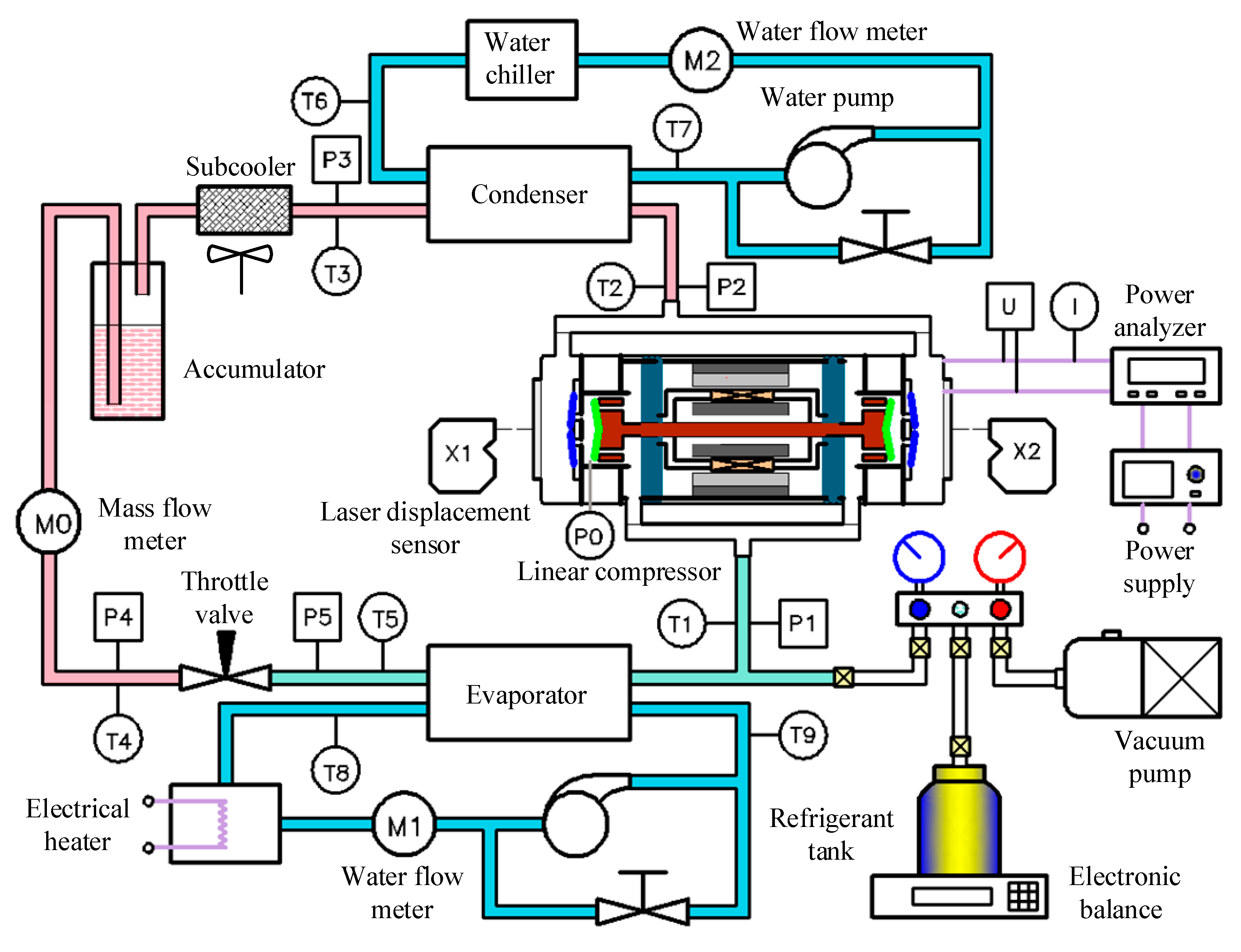
A test rig built to study the linear compressor is shown in Figure 3. It included a refrigeration system, two heat exchanger water systems, a refrigerant charging system, a power supply control system and a data acquisition system. The refrigeration system mainly consisted of a linear compressor, a condenser, a subcooler, a throttle valve, an evaporator, an accumulator, a drying filter and a mass flowmeter. Firstly, low-temperature and low-pressure gas was compressed to high-temperature and high-pressure gas in a linear compressor. Secondly, the gas was cooled to a high-pressure and supercooling liquid by the water system connected with condenser. Next, the gas was throttled to a gas liquid two-phase substance with a low temperature and low pressure in the throttle valve. Finally, the gas was heated to a superheating gas by a water system connected with the evaporator and returned to the linear compressor. A water chiller was connected with the condenser to keep the internal pressure of the condenser constant. The electric heating water system was connected with the evaporator, and the cooling capacity of the system was balanced by the electric heating power. The superheat of the system was controlled by adjusting the electric heating power and water mass flow rate of the evaporator water circulation, and the subcooling of the system was controlled by adjusting the fan speed of the air-cooled subcooler. The power supply control system included a power supply, a power meter, a laser displacement sensor and an oscilloscope. The piston displacement was measured by the laser displacement sensor in real time and displayed on the oscilloscope.
A Coriolis mass flowmeter was installed behind the liquid reservoir to measure the mass flow of the liquid refrigerant and obtain the cooling capacity. Two turbine flowmeters were installed in the water loops to obtain the heat exchange capacity of the evaporator and the condenser. Nine temperature sensors and five static pressure sensors were installed at the inlet and outlet of the key components, respectively. A dynamic pressure sensor was installed on the front of the cylinder in order to obtain the real-time pressure of the cylinder. A laser displacement sensor wass installed to measure the real-time displacement of the discharge valve, and a Hall current sensor was installed behind the power meter to obtain the real-time current. The key parameters of the instruments are shown in Table 3.
2.3. Date Acquisition System
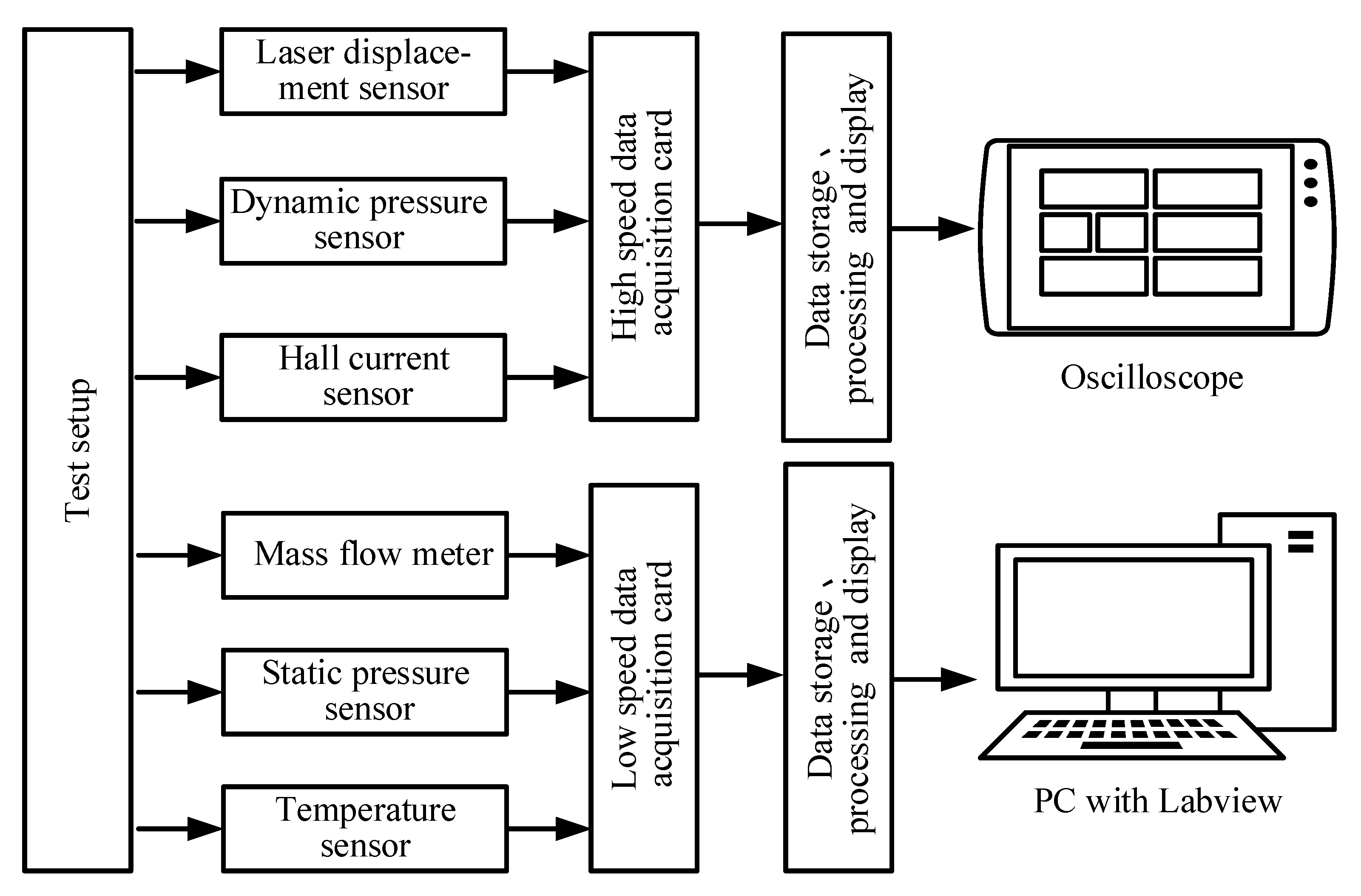
The data acquisition system is presented in Figure 4. A LeCroy HDO6000A high-definition oscilloscope and a Keithley 7700 low-speed data acquisition card were the key units of the data acquisition system. The high-speed data acquisition system consisted of an oscilloscope, two laser displacement sensors, a hall current sensor and a dynamic pressure sensor. The high-speed signals were collected, displayed and stored on the oscilloscope, and the sampling rate was set to 250 kHz. The low-speed data acquisition system included three mass flow meters, five static pressure sensors and nine temperature sensors. The low-speed signals were displayed and stored in the LabVIEW software of the computer, and the sampling rate was set to 1 Hz.
2.4. Test Conditions
Table 4 lists the test conditions of the linear compressor. The test rig was charged with a suitable amount of R134a (1.4 kg). The evaporation pressure was set to 0.35 MPa, and the condensation pressure was set to 0.887 MPa under the design conditions of the dual-piston linear compressor. In the experiment on cooling capacity regulation, the piston stroke was controlled from 8.0 mm to 10.5 mm (the interval was 0.5 mm), and the driving frequency range was 50–70 Hz. In the test under air conditioning, the stroke was set to 10 mm, the evaporation pressure was set to 0.415 MPa and 0.377 MPa, and the condensation pressure was set to 1.160 MPa and 1.47 MPa. The superheat was maintained at 10 ± 2 °C, the subcooling was held at 3 ± 2 °C, and the ambient temperature was kept at 25 ± 2 °C.
For a certain working conditions, the stroke and frequency were manually controlled by the NF power supply, while the working pressure was manually controlled by the inlet water temperature and mass flow rate of the condenser water system and the opening of the throttle valve. When the temperature fluctuation of the system was not higher than ±0.5 K within 10 min, the system was considered stable. It took about 30 min for the system to go from one steady state to another.
3. Operating Characteristics at Resonance
Compared with the single-piston linear compressor, the dual-piston compressor driven by a moving coil motor had two opposite gas compression systems which greatly changed the force of the compressor mover and made its operation characteristics very different from the single piston. The study of operation characteristics is very helpful to understand the working mechanism of a dual-piston linear compressor.
3.1. P-V Diagram
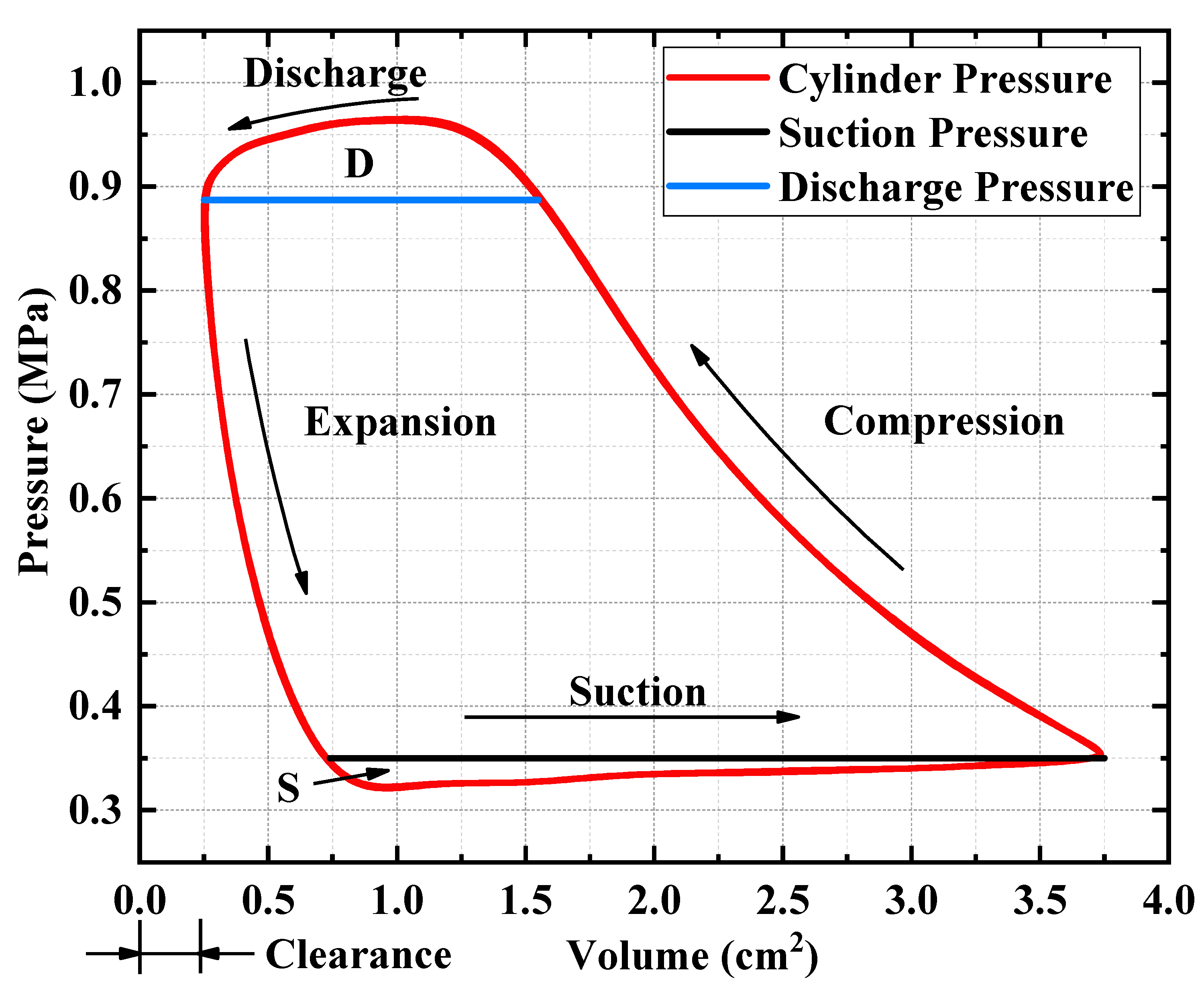
A Pressure-Volume diagram (P-V diagram) is an important tool to display compressor performance. The real-time pressure in the cylinder was measured by a dynamic pressure sensor installed in the cylinder wall, and the real-time volume in the cylinder could be calculated by the piston position, measured by a laser displacement sensor. The calculation formula of the single-cylinder volume is as follows:
where is the volume in the front of the cylinder at a certain moment (cm3), is the cross-sectional area of the cylinder (cm2) and is the initial clearance length (cm).
The conditions of the left cylinder and the right cylinder were exactly same, which determined that the P-V diagram was also the same. Figure 5 shows the P-V diagram of a single cylinder at a resonant frequency (60 Hz) under the design conditions. The compression process, discharge process, expansion process and suction process can be clearly seen. The area of S enclosed by the suction pressure and cylinder pressure represents the suction loss, while the area of D enclosed by the discharge pressure and cylinder pressure represents the discharge loss. It can be easily seen that the discharge loss was higher than the suction loss. The clearance volume was 0.25 cm2, and the clearance volume accounted for 7.1% of the scavenging volume (i.e., the volume was swept by a piston in one stroke).
3.2. Gas Force and Piston Offset
Both the left piston and the right piston were affected by a fluctuating gas force in the cylinder and a stable gas force in the chamber behind the piston (i.e., the back pressure chamber). The formula for calculating the gas force acting on a single piston is as follows:
where is the gas force acting on the piston (N), is the gas pressure in the cylinder (MPa) and is the gas pressure in the back pressure chamber (MPa).
It is worth noting that the suction pipeline was connected with the back pressure chamber of the compressor, and the gas pressure in the back pressure chamber was the same as the suction pressure.
The gas force acting on the dual piston is the sum of the forces acting on the left and right pistons, and its formula for calculation is as follows:
where is the gas force acting on the left piston (N) and is the gas force acting on the right piston (N).
The mean gas force is the fundamental power of the piston offset, and the mechanical spring provides a reverse spring force to prevent the piston offset until the force balance is achieved. The calculation formula of the piston offset can be obtained as follows:
where is the piston offset (mm) and is the mean gas force acting on the dual piston (N).
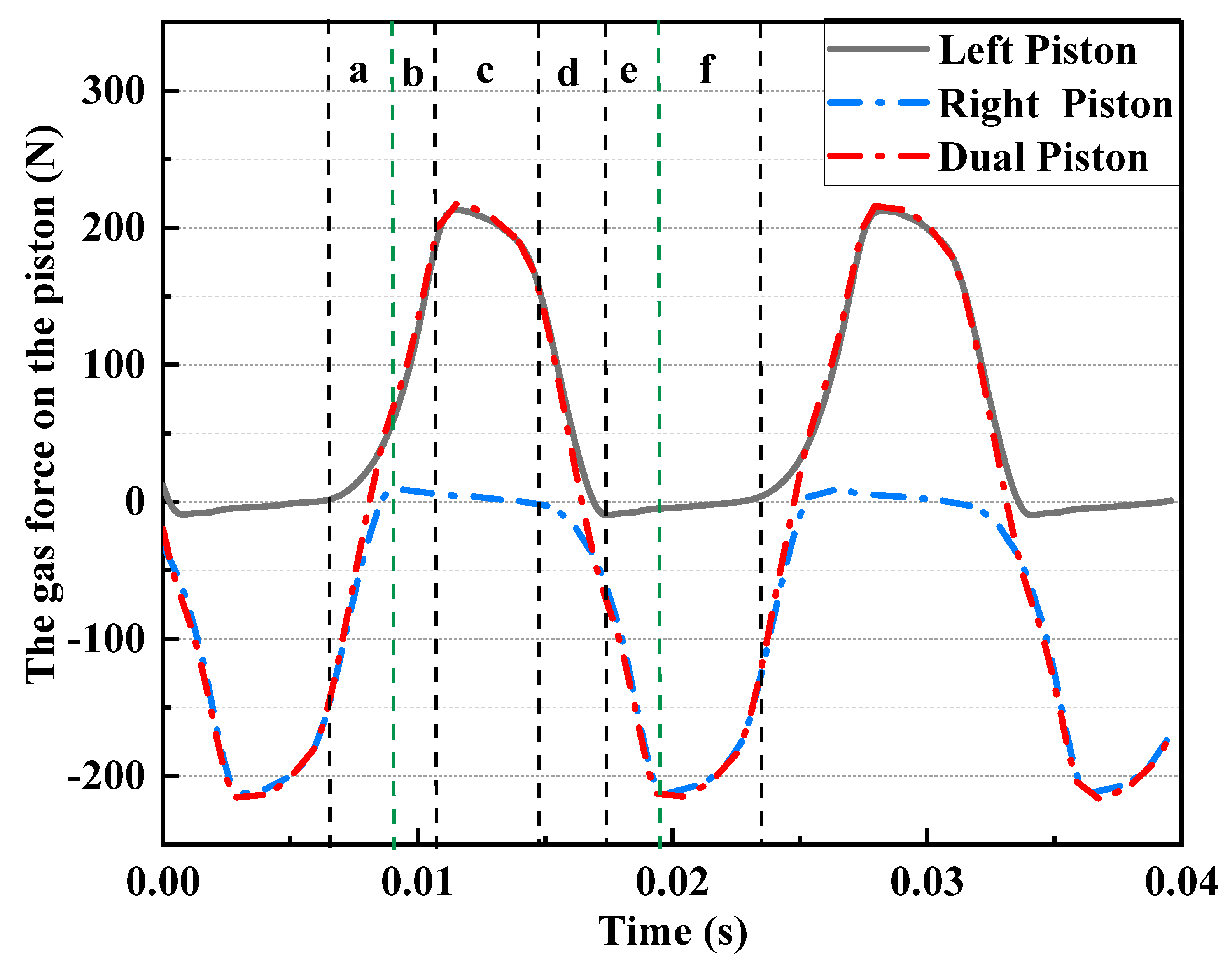
Figure 6 shows the gas force waveforms on the left piston, the right piston and the dual piston under the design conditions (i.e., evaporation pressure of 0.35 MPa and condensation pressure of 0.887 MPa) at a resonant frequency. Most of the time, the gas force waveform of the left or right piston was located on one side of the Y-axis (i.e., positive Y-axis or negative Y-axis), and the mean gas force on the single piston compressor was far away from zero, which led to the large piston offset. The gas force waveform acting on the dual piston was evenly distributed on both sides of the Y-axis (i.e., positive Y-axis and negative Y-axis). Its mean value was very close to zero, so the piston was almost not offset. The six time periods of a–f in Figure 6 correspond to the six processes of the dual-piston compressor in Table 1. The amplitude of the gas force on the dual piston was slightly larger than that on the single piston, and the gas force on dual piston was more sinusoidal than that on the single piston. The dual piston structure driven by a motor determined that the process in the two cylinders was not synchronous and the time difference was half a cycle. The superposition of the gas forces acting on the left piston and the right piston resulted in a good sinusoidal gas force on the dual piston.
The piston offset made it difficult to detect the piston displacement in real time, which increased the risk of the compressor hitting the valve plate and improving the difficulty of compressor control. Besides that, the piston offset could also lead to a reduction in motor efficiency (motor coefficient decreasing), a reduction in volumetric efficiency (dead volume increasing) and a reduction in flexible spring reliability (spring displacement increasing). Table 5 lists the comparison of the experimental mean gas force and the experimental piston offset between the single piston and dual pistons under the design conditions at 60 Hz. The experimental average gas force and experimental piston offset of the dual pistons (dual-piston compressor) were almost zero. The mean experimental gas force and piston offset of the left piston were much larger than the dual pistons. This proved that the dual-piston structure could greatly reduce the piston offset. The drastic reduction of the piston offset could bring four benefits: improving the power factor and motor efficiency, reducing the stress of the flexure springs, increasing the volumetric efficiency and reducing the difficulty of electronic control.
3.3. Current and Electromagnetic Force Waveform
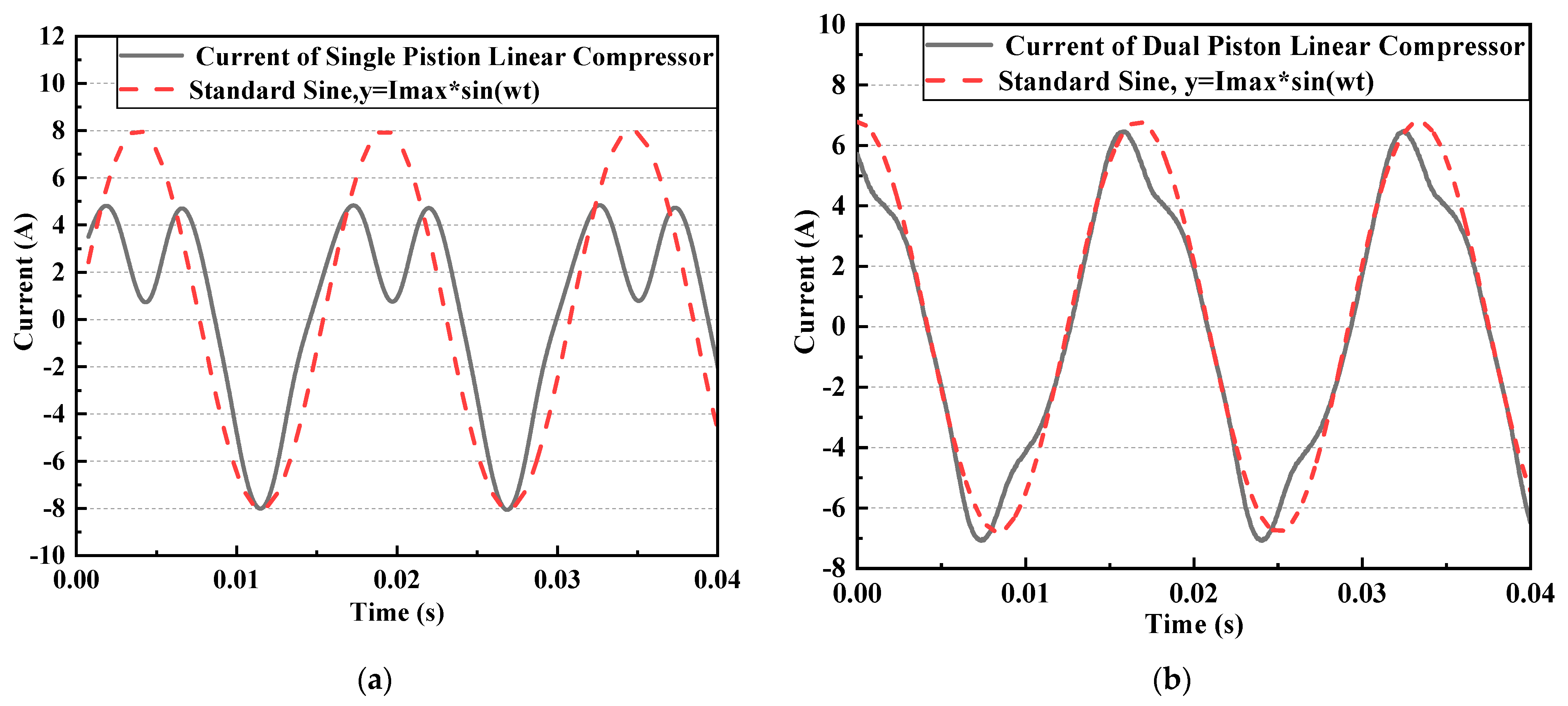
Figure 7a shows the comparison between the current waveform and the standard sinusoidal waveform of the single-piston moving coil linear compressor (the cylinder diameter was 26 mm) at the resonance frequency (65 Hz) at 10 mm under the design conditions. The current of the single-piston linear compressor had a unique nonsinusoidal distortion, and there were two peaks in the positive half axis of the current at the resonance frequency. Sun at al. [28] reported the unique nonsinusoidal current distortion phenomenon, and he explained that the nonlinearity of gas force caused the phenomenon. The dual-piston compressor (the cylinder diameter was 21 mm) adopted the same motor as the single-piston moving coil linear compressor, and the motor parameters and mechanical spring parameters were completely same. Figure 7b shows the comparison between the current and the standard sinusoidal waveform of the dual-piston linear compressor at the resonance frequency (60 Hz) under the design conditions. It can be seen that the current only had a very small nonsinusoidal deformity at the peak and trough, and the current was very close to the sinusoidal waveform on the whole, which was completely different from the current law of the single-piston compressor. The different current waveforms of the single-piston linear compressor and the dual-piston linear compressor fully demonstrated that the current deformity came from the nonlinearity of the gas force.
The motor coefficient of the moving coil linear motor could be considered as constant in the design stroke. The electromagnetic force under different currents can be calculated by the following formula:
where is the electromagnetic force (N).
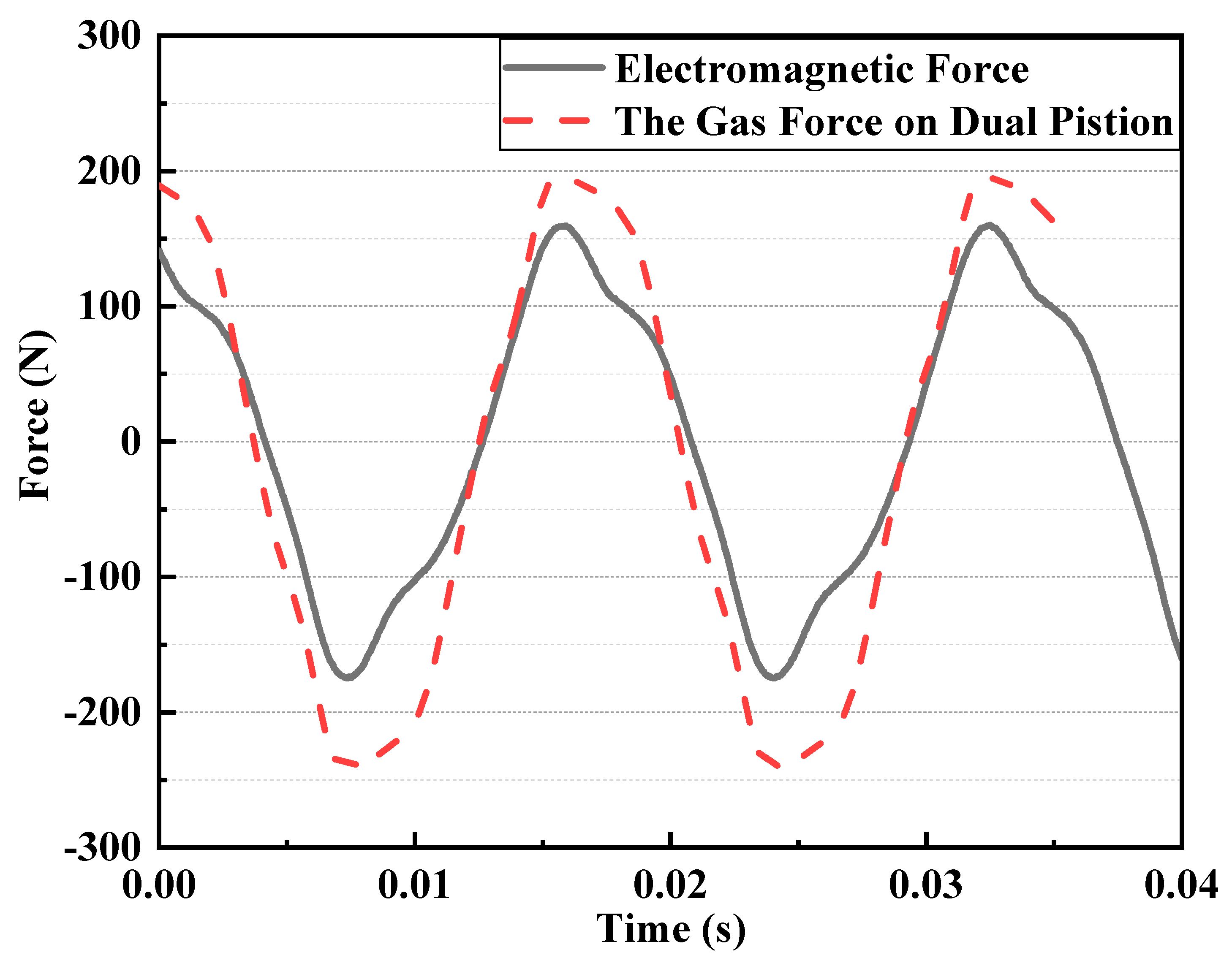
Figure 8 shows the comparison between the electromagnetic force and the gas force acting on the dual piston at the resonance frequency (60 Hz) under the design conditions. It can be seen that the phase of the electromagnetic force and the gas force were the same at resonance, and the electromagnetic force and gas force acting on the dual piston were close to sinusoidal. Considering that the inertia force, equivalent damping force and mechanical spring force are sinusoidal, it can be concluded that the sinusoidal gas force of the dual-piston compressor fundamentally led to the sinusoidal electromagnetic force and current, and the serious nonlinear distortion of the gas force of the single-piston compressor resulted in the nonlinear distortion of electromagnetic force and current.
4. Variable Cooling Capacity Regulation
4.1. Compressor Performance
Figure 9a shows the mass flow rate and power input under a variable frequency. It can be seen that the mass flow rate and power input increased approximately linearly with the frequency, and the trends were highly nonlinear at 60 Hz ± 5 Hz. This reflects the resonance characteristics of the linear compressor, and linear compressors can use less input power to achieve a greater stroke. The maximum mass flow rate was 6.11 g/s when the input power was 223 W at 70 Hz. This can be explained by the compressor discharge volume being proportional to the frequency at the same suction density and stroke.
Figure 9b shows the mass flow rate and power input as a function of the stroke. It can be seen that the mass flow rate increased linearly with the stroke. This was because the compressor discharge volume was proportional to the stroke at the same suction density and frequency. The maximum mass flow was 5.55 g/s when the input power was 180 W at 10.5 mm. The input power increased approximately linearly with the stroke. This can be explained by the input power being proportional to the mass flow, and a larger mass flow requires more input power.
The main power loss of the moving coil linear motor was the Joule heat from the coil, so the motor efficiency can be obtained from the following formula:
where is the motor efficiency, is the root mean square, is the copper resistance (Ω) and is the power input (W).
The power factor of the linear motor reflects the utilization ratio of the power input. The formula to calculate this is as follows:
where is the power factor, is the driving voltage (V) and is the time period (s).
The linear compressor had two compression chambers, and its volumetric efficiency was obtained from the following formula:
where is the volumetric efficiency, is the mass flow rate (kg/s), is the suction density of the compressor (kg/m3), is the piston stroke (m) and is the driving frequency (Hz).
The isentropic efficiency of the linear compressor is expressed as follows:
where is the isentropic efficiency, is the isentropic discharge enthalpy of the compressor (kJ/kg) and is the suction enthalpy of the compressor (kJ/kg).
Figure 10a shows the power factor, motor efficiency, volumetric efficiency and isentropic efficiency under a variable frequency at a fixed stroke of 10 mm. The results show that the power factor and the motor efficiency nearly followed a symmetric trend across the frequency. The maximum power factor was 99.0%, and the maximum motor efficiency was 87.9% at 60 Hz. Therefore, the resonance frequency under the design condition was 60 Hz. When the driving frequency deviated from the resonance frequency by 5 Hz, the motor efficiency decreased to 85.8%. The volumetric efficiency was almost constant, which was 76.7%. The isentropic efficiency also followed a symmetric trend against the frequency. The maximum isentropic efficiency (63.3%) occurred at the resonance frequency (60 Hz), and the isentropic efficiency decreased to 60.2% at 60 Hz ± 5 Hz. The extremely sinusoidal current of the dual piston linear compressor had few of the higher harmonic components, and the phase of the current was very close to that of the voltage at resonance (i.e., the two waveforms were almost coincident), which significantly improved the power factor. The non-offset of the motor mover (i.e., the piston offset) of the dual-piston linear compressor ensured that the motor mover always ran in the maximum magnetic field, which avoided the decrease of the motor coefficient for the piston offset and reduced the driving current. This is the reason why the motor efficiency of the dual-piston linear compressor was high. The compressor clearance volume, working pressure, cylinder heat transfer state and valve leakage were almost constant at different frequencies. Thus, the volumetric efficiency was nearly constant in the variable frequency experiment.
Figure 10b shows the power factor, motor efficiency, volumetric efficiency and isentropic efficiency under a variable stroke at a fixed frequency of 60 Hz. The power factor increased first and then was static against the stroke, and the motor efficiency was almost constant against the stroke, which was 87.9%. This was because the variation of the gas force stiffness caused by the stroke was small, which had a particularly weak effect on the resonance frequency. The volumetric efficiency increased linearly against the stroke, and the maximum volumetric efficiency was 79.1% at 10.5 mm. This can be explained by the clearance volume at the front of the piston decreasing with an increasing stroke, which improved the volumetric efficiency. The maximum isentropic efficiency was 63.7%, which was obtained at 10.5 mm. This was due to the mass flow and input power increasing linearly with the stroke.
4.2. System Efficiency
The cooling capacity measured by the refrigerant flowmeter method was obtained by the following formula:
where is the cooling capacity calculated by the refrigerant flowmeter (W) and is the inlet enthalpy of the evaporator (kJ/kg).
The cooling capacity measured by the water flowmeter method was obtained by the following formula:
where is the cooling capacity calculated by water flowmeter (W), is the specific heat capacity of the water (kJ/(kg·K)), is the mass flow rate of the evaporator inlet water (g/s), is the outlet water temperature of the evaporator (k) and is the inlet water temperature of the evaporator (k).
Figure 11 shows the comparison of the cooling capacities calculated by the refrigerant flowmeter method and the water flowmeter method in the changing frequency experiment. It can be seen that the cooling capacities calculated by the two methods coincided greatly, and the maximum error of the cooling capacity was no more than 2.5%, which proved that the test platform had good accuracy.
The coefficient of performance (COP) was obtained from the following formula:
where is the average value of the cooling capacity calculated by the water flowmeter and the cooling capacity calculated by the refrigerant flowmeter [W].
Figure 12a shows the COP and cooling capacity under variable driving frequencies with a fixed stroke of 10 mm. The cooling capacity increased linearly with an increasing frequency, and the trends were nonlinear at 60 Hz ± 5 Hz, while the COP followed a nearly symmetric trend across the frequency. The maximum COP was 5.2, and the cooling capacity was 866 W when the driving frequency was the resonant frequency (60 Hz). This phenomenon was due to the fact that the increasing rate of the cooling capacity was higher than the increasing rate of the input power with the frequency at the resonance frequency. When the driving frequency deviated from the resonance frequency by 5 Hz, the COP decreased to 4.86.
Figure 12b shows the COP and cooling capacity under a variable stroke at a fixed driving frequency of 60 Hz. The cooling capacity and COP increased approximately linearly against the stroke. The maximum COP was 5.21, and the maximum cooling capacity was 938 W when the stroke was 10.5 mm. This was because the cooling capacity and input power increased linearly with the stroke.
The Carnot efficiency () was obtained by the following formula:
where is the evaporation temperature (K) and is the condensation temperature (K).
The normalized COP (i.e., the relative Carnot efficiency) was obtained by the following formula:
where is the normalized COP.
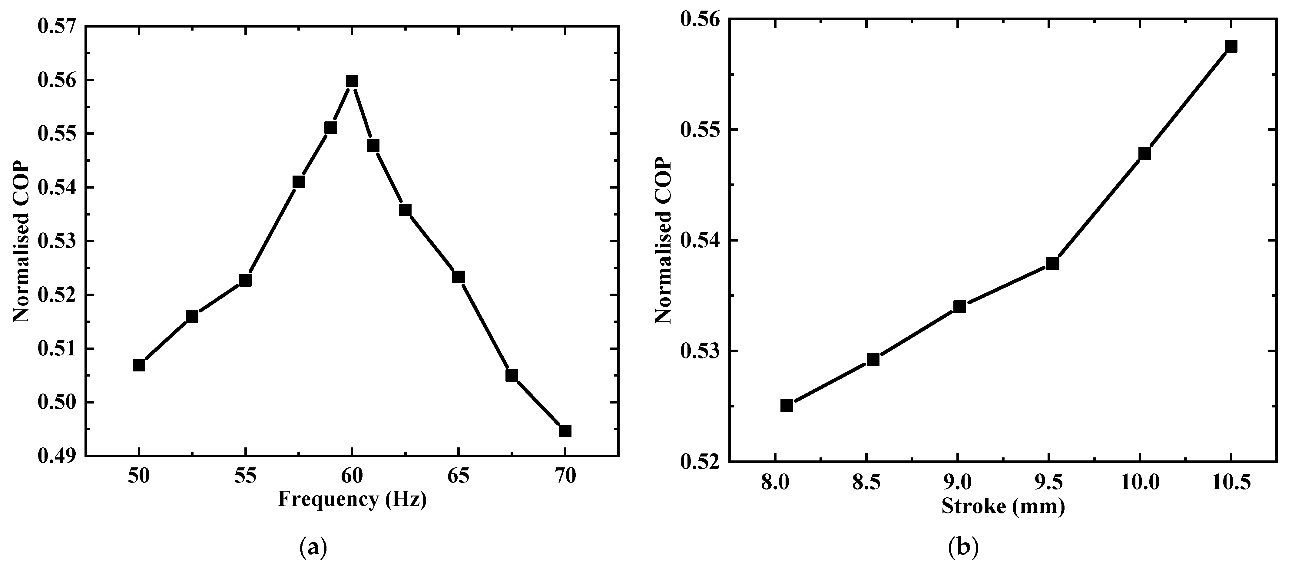
The normalized COP under a variable frequency is shown in Figure 13a. The normalized COP followed a nearly symmetrical trend across the frequency, and the maximum normalized COP (55.7%) was obtained at 60 Hz. The normalized COP under a variable stroke is shown in Figure 13b. The normalized COP increased approximately linearly with the increasing stroke. The maximum normalized COP was 55.8% with a stroke of 10.5 mm.
4.3. Comparison of Two Variable Capacity Methods
Different from the start-stop regulation and frequency regulation of the traditional compressor [29,30,31], a linear compressor can regulate the cooling capacity by changing driving frequency and piston stroke [32,33]. The research on cooling capacity regulation of a linear compressor are focused on single-piston linear compressors, while the research on cooling capacity regulation of dual-piston linear compressors is very scarce.
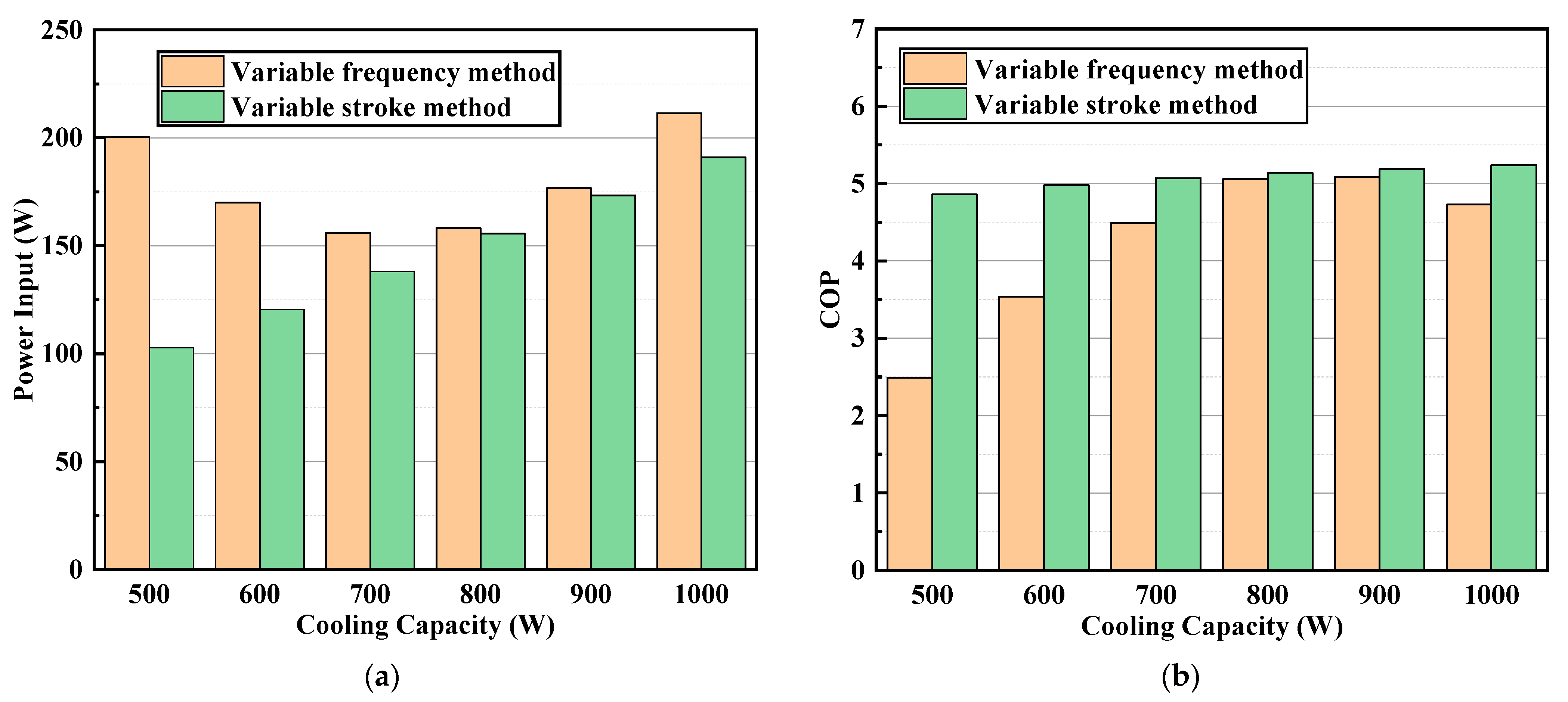
Table 6 shows the comparison between frequency regulation and stroke regulation. The data in the table was interpolated according to the results of the variable frequency and stroke experiments. The cooling capacity increasing from 500 W to 1000 W could be obtained by linearly increasing the drive frequency from 36 Hz to 69 Hz at a stroke of 10 mm or linearly increasing the stroke from 8.0 mm to 10.8 mm at 60 Hz. The comparison of the power input and COPs of the two cooling capacity regulation methods is shown in Figure 14. Compared with the variable frequency method, the variable stroke method had lower power input and a higher COP. From the perspective of energy saving, the variable stroke method was the best choice for the dual-piston linear compressor. In addition, the cooling capacity, input power and COP were linearly increasing against the stroke and the piston stroke to be inferred from the above quantities, which allowed no displacement sensor to be installed on the dual-piston linear compressor. The lack of displacement sensors helped reduce the compressor cost, reduce the volume and weight of the linear compressor and realize miniaturization.
5. Comparison with a Crank-Driven Compressor
A commercial crank-driven reciprocating compressor (the model was EMT50 HDP, and the swept volume was 4.5 cm2) for air conditioning produced by Embraco was selected for comparison with the dual-piston linear compressor. The comparison of refrigeration performance of the two compressors is shown in Table 7. The COP of the dual-piston linear compressor was 38%, 24% and 12% higher than the commercial crank-driven reciprocating compressor at the pressure ratios of 2.54 (design condition), 2.80 (practical air conditioning conditions) and 3.9 (ASHRAE-T air conditioning condition), respectively, and the normalized COP was 0.158, 0.101 and 0.054 higher than the crank-driven reciprocating compressor, respectively. This reflects the efficiency advantage of the dual-piston linear compressor in household refrigeration. High efficiency of the linear motor, high mechanical efficiency due to the lack of an inefficient crank mechanism and high heat transfer efficiency in the heat exchangers due to a lack of lubricating oil enhanced the COP of the dual-piston linear compressor.
6. Experimental Uncertainty
In the experiment, the stroke, voltage, current, frequency, pressure, temperature, refrigerant mass flow rate and water mass flow rate were measured directly. The measured values of the stroke, voltage, current, frequency and temperature had absolute uncertainties of 0.1 μm, 0.1 V, 0.1 A, 0.1 Hz and 0.1 K, respectively. The accuracies of the power meter, static pressure sensor, dynamic pressure sensor, Coriolis mass flowmeter and turbine water flow meter were 0.5%, 0.5%, 0.25%, 0.2% and 1.0%, respectively. The propagated uncertainties of the indirect calculated parameters, such as the volume, gas force, electromagnetic force, motor efficiency, volumetric efficiency, isentropic efficiency, cooling capacity, COP and normalized COP, could be calculated according to an uncertainty transfer function. Table 8 shows the propagated uncertainties of the derived parameters.
7. Conclusions
A novel, oil-free dual piston compressor driven by a moving coil linear motor was developed and tested in a refrigeration system with R134a. First, the P-V diagram, current waveform, gas force waveform and electromagnetic force waveform at the resonance frequency were studied. Secondly, the two cooling capacity regulation methods of variable frequency and variable stroke were compared experimentally. Finally, the performance of the dual-piston compressor and commercial crank-driving reciprocating compressor were also compared.
- The waveform of the gas force and electromagnetic force (current) of the dual-piston linear compressor were very close to being standard sinusoidal, which led to a higher power factor and motor efficiency than the single-piston linear compressor. The mean gas force of the dual-piston linear compressor was extremely close to zero, and its piston was almost not offset. The drastic reduction of piston offset can bring four benefits: improving the power factor and motor efficiency, reducing the stress of the flexure springs, increasing the volumetric efficiency and reducing the difficulty of electronic control;
- Off-resonance measurements showed that when the driving frequency deviated from the resonance frequency by 5 Hz, the motor efficiency, isentropic efficiency, COP and normalized COP of the dual-piston linear compressor decreased by 2.4%, 4.8%, 6.8% and 6.6%, respectively, which indicated the importance of keeping the dual-piston linear compressor operating in resonance;
- The variable stroke method had lower power consumption and higher efficiency than the variable frequency method. From the perspective of energy saving, cost and miniaturization, the variable stroke method was more suitable for cooling capacity regulation for the dual-piston linear compressor;
- The maximum COP, motor efficiency, volumetric efficiency and isentropic efficiency of the dual-piston linear compressor were 5.34, 87.9%, 79.1% and 63.7%, respectively;
- The COP of the linear compressor was 38%, 24% and 12% higher than the commercial crank-driven reciprocating compressor at the pressure ratios of 2.54, 2.80 and 3.9, respectively, which reflects the efficiency advantage of the dual-piston linear compressor in household refrigeration.
Author Contributions
Conceptualization, J.C. and J.S.; methodology, J.L. and J.S.; software, J.S.; validation, J.S., Y.L. and Z.H.; formal analysis, J.S.; investigation, J.S.; resources, J.C.; data curation, J.S.; writing—original draft preparation, J.S.; writing—review and editing, J.S., Y.L. and Z.H.; visualization, J.S.; supervision, J.C. and J.L.; project administration, J.L.; funding acquisition, J.C. All authors have read and agreed to the published version of the manuscript.
Funding
This study was supported by the National Natural Science Foundation of China (Grant No. 51776213) and the Strategic Priority Research Program of Chinese Academy of Sciences (Grant No. XDA18000000 and No. XDA18040000).
Institutional Review Board Statement
Not applicable.
Informed Consent Statement
Not applicable.
Data Availability Statement
Not applicable.
Conflicts of Interest
The authors declare no conflict of interest.
References
- Li, Z.; Jiang, H.; Chen, X.; Liang, K. Comparative study on energy efficiency of low GWP refrigerants in domestic refrigerators with capacity modulation. Energy Build. 2019, 192, 93–100. [Google Scholar] [CrossRef]
- Buffa, S.; Cozzini, M.; D’Antoni, M.; Baratieri, M.; Fedrizzi, R. 5th generation district heating and cooling systems: A review of existing cases in Europe. Renew. Sustain. Energy Rev. 2019, 104, 504–522. [Google Scholar] [CrossRef]
- Tong, Z.; Chen, Y.; Malkawi, A.; Liu, Z.; Freeman, R. Energy saving potential of natural ventilation in China: The impact of ambient air pollution. Appl. Energy 2016, 179, 660–668. [Google Scholar] [CrossRef] [Green Version]
- Ma, Z.; Song, J.; Zhang, J. Energy consumption prediction of air-conditioning systems in buildings by selecting similar days based on combined weights. Energy Build. 2017, 151, 157–166. [Google Scholar] [CrossRef]
- Li, C.; Li, J.; Tang, L.; Sun, J.; Zou, H.; Cai, J. Effects of the driving voltage waveform on the performance of vapor compression cycle system driven by the moving coil oil-free linear compressor. Int. J. Refrig. 2019, 108, 200–208. [Google Scholar] [CrossRef]
- Zhu, Z.; Liang, K.; Li, Z.; Jiang, H.; Meng, Z. Thermal-economic-environmental analysis on household refrigerator using a variable displacement compressor and low-GWP refrigerants. Int. J. Refrig. 2021, 123, 189–197. [Google Scholar] [CrossRef]
- Jiang, H.; Liang, K.; Li, Z. Characteristics of a novel moving magnet linear motor for linear compressor. Mech. Syst. Signal Process. 2019, 121, 828–840. [Google Scholar] [CrossRef]
- Liang, K. A review of linear compressors for refrigeration. Int. J. Refrig. 2017, 84, 253–273. [Google Scholar] [CrossRef]
- Barbosa, J.R., Jr.; Ribeiro, G.B.; de Oliveira, P.A. A State-of-the-Art Review of Compact Vapor Compression Refrigeration Systems and Their Applications. Heat Transf. Eng. 2012, 33, 356–374. [Google Scholar] [CrossRef]
- Liang, K.; Stone, R.; Dadd, M.; Bailey, P. A novel linear electromagnetic-drive oil-free refrigeration compressor using R134 a. Int. J. Refrig. 2014, 40, 450–459. [Google Scholar] [CrossRef]
- Bradshaw, C.; Groll, E.; Garimella, S. A comprehensive model of miniature-scale linear compressor for electronics cooling. Int. J. Refrig. 2011, 34, 63–73. [Google Scholar] [CrossRef] [Green Version]
- Bradshaw, C.R.; Groll, E.A.; Garimella, S.V. Linear compressors for electronics cooling: Energy recovery and its benefits. Int. J. Refrig. 2013, 36, 2007–2013. [Google Scholar] [CrossRef]
- Park, K.; Hong, E.; Lee, H. Linear motor for linear compressor. In Proceedings of the International Compressor Engineering Conference, West Lafayette, IN, USA, 16–19 July 2002. [Google Scholar]
- Liang, K.; Stone, R.; Hancock, W.; Dadd, M.; Bailey, P. Comparison between a crank-drive reciprocating compressor and a novel oil-free linear compressor. Int. J. Refrig. 2014, 45, 25–34. [Google Scholar] [CrossRef]
- Bansal, P.; Vineyard, E.; Abdelaziz, O. Advances in household appliances—A review. Appl. Therm. Eng. 2011, 31, 3748–3760. [Google Scholar] [CrossRef]
- Unger, R. Development and testing of a linear compressor sized for the European market. In Proceedings of the International Appliance Technology Conference, West Lafayette, IN, USA, 10–12 May 1999. [Google Scholar]
- Li, C. Study of Compression Efficiency of a Vapor Compression Refrigeration Cycle Driven by Linear Motor. Ph.D. Thesis, University Chinese Academy of Sciences, Beijing, China, 2019. [Google Scholar]
- Bradshaw, C. A Miniature-Scale Linear Compressor for Electronics Cooling. Ph.D. Thesis, Purdue University, West Lafayette, IN, USA.
- Zou, H.; Li, X.; Tang, M.; Tian, C.; Chen, X. Performance analysis of linear compressor using R290 for commercial refrigerator. Int. J. Refrig. 2020, 109, 55–63. [Google Scholar] [CrossRef]
- Puff, R.; Lilie, D.; Knies, M. Linear Compressor Suction Valve Optimization. In Proceedings of the International Compressor Engineering Conference, West Lafayette, IN, USA, 11–14 July 2016. [Google Scholar]
- Lilie, D.; Puff, R.; Bortoli, M. Linear Compressor Discharge Manifold Design for High Thermal Efficiency. In Proceedings of the International Compressor Engineering Conference, West Lafayette, IN, USA, 11–14 July 2016. [Google Scholar]
- Jomde, A.; Anderson, A.; Bhojwani, V.; Kedia, S.; Jangale, N.; Kolas, K.; Khedkal, P. Modeling and measurement of a moving coil oil-free linear compressor performance for refrigeration application using R134 a. Int. J. Refrig. 2018, 88, 182–194. [Google Scholar] [CrossRef]
- Lee, H.; Sang, S.; Lee, C.; Lee, H. Linear compressor for air-conditioner. In Proceedings of the International Compressor Engineering Conference, West Lafayette, IN, USA, 12–15 July 2004. [Google Scholar]
- Herrmann, D. Small electric refrigerating machine. U.S. Patent 2,679,732, 1 June 1954. [Google Scholar]
- Zou, H. Development and investigation of dual-cylinder linear compressor. Ph.D. Thesis, University Chinese Academy of Sciences, Beijing, China, 2010. [Google Scholar]
- Zou, H.; Zhang, L.; Peng, G.; Tian, C. Experimental investigation and performance analysis of a dual-cylinder opposed linear compressor. J. Mech. Sci. Technol. 2011, 25, 1885–1892. [Google Scholar] [CrossRef]
- Wei, Y.; Zuo, Z.; Jia, B.; Feng, H.; Liang, K. Influence of piston displacement profiles on the performance of a novel dual piston linear compressor. Int. J. Refrig. 2020, 117, 71–80. [Google Scholar] [CrossRef]
- Sun, J.; Li, C.; Li, J.; Li, J.; Cai, J. Experimental and Theoretical Investigation of Nonlinear Dynamic characteristics in an Oil-free Moving Coil Linear Compressor. In Proceedings of the 7th International Conference on Mechanical Engineering, Materials Science and Civil Engineering (ICMEMSCE), Sanya, China, 17–18 December 2019. [Google Scholar]
- Li, B.; Alleyne, A. Optimal on-off control of an air conditioning and refrigeration system. In Proceedings of the 2010 American Control Conference, Baltimore, MD, USA, 30 June–2 July 2010; pp. 5892–5897. [Google Scholar]
- Yan, G.; Liu, Y.; Qian, S.; Yu, J. Theoretical study on a vapor compression refrigeration system with cold storage for freezer applications. Appl. Therm. Eng. 2019, 160, 114091. [Google Scholar] [CrossRef]
- Cho, H.; Kim, Y.; Jang, I. Performance of a showcase refrigeration system with multi-evaporator during on–off cycling and hot-gas bypass defrost. Energy 2005, 30, 1915–1930. [Google Scholar] [CrossRef]
- Heo, K.; Lee, C.; Song, G.; Jung, W. Capacity modulation of linear compressor for household refrigerator. In Proceedings of the International Compressor Engineering Conference, West Lafayette, IN, USA, 12–15 July 2004. [Google Scholar]
- Lee, H.K.; Song, G.Y.; Park, J.S.; Hong, E.P.; Jung, W.H.; Park, K.B. Development of the linear compressor for a household refrigerator. In Proceedings of the International Compressor Engineering Conference, West Lafayette, IN, USA, 25–28 June 2000. [Google Scholar]
Figure 1.
Structure diagram of the dual-piston linear compressor.

Figure 2.
The forces acting on the dual-piston assembly.

Figure 3.
Test rig for the dual-piston linear compressor (P = the pressure sensor and T = the temperature sensor).
Figure 3.
Test rig for the dual-piston linear compressor (P = the pressure sensor and T = the temperature sensor).

Figure 4.
Data acquisition system.

Figure 5.
P-V diagram of a single cylinder at 60 Hz under the design conditions.

Figure 6.
Gas force waveforms acting on the left piston, right piston and dual piston at 60 Hz under the design conditions.
Figure 6.
Gas force waveforms acting on the left piston, right piston and dual piston at 60 Hz under the design conditions.

Figure 7.
Comparison of the current waveform and standard sinusoidal waveform for (a) the single-piston linear compressor (the cylinder diameter was 26mm) at the resonance frequency (65 Hz) under the design condition and (b) the dual-piston linear compressor (the cylinder diameter was 21 mm) at the resonance frequency (60 Hz) under the design conditions.

Figure 8.
Comparison of the electromagnetic force and gas force acting on the dual piston at the resonance frequency (60 Hz) under the design conditions.
Figure 8.
Comparison of the electromagnetic force and gas force acting on the dual piston at the resonance frequency (60 Hz) under the design conditions.

Figure 9.
Mass flow and input power under design conditions. (a) The fixed stroke is 10 mm, and the independent variable is the frequency. (b) The fixed frequency is 60 Hz, and the independent variable is the stroke.
Figure 9.
Mass flow and input power under design conditions. (a) The fixed stroke is 10 mm, and the independent variable is the frequency. (b) The fixed frequency is 60 Hz, and the independent variable is the stroke.

Figure 10.
Power factor, motor efficiency, volumetric efficiency and isentropic efficiency at the resonance frequency. (a) The fixed stroke is 10 mm, and the independent variable is the frequency. (b) The fixed frequency is 60 Hz, and the independent variable is the stroke.
Figure 10.
Power factor, motor efficiency, volumetric efficiency and isentropic efficiency at the resonance frequency. (a) The fixed stroke is 10 mm, and the independent variable is the frequency. (b) The fixed frequency is 60 Hz, and the independent variable is the stroke.

Figure 11.
Comparison of the cooling capacities calculated by the refrigerant flowmeter method and the water flowmeter method.
Figure 11.
Comparison of the cooling capacities calculated by the refrigerant flowmeter method and the water flowmeter method.

Figure 12.
Coefficient of performance (COP) and cooling capacity at the resonance frequency. (a) The fixed stroke is 10 mm, and the independent variable is the frequency. (b) The fixed frequency is 60 Hz, and the independent variable is the stroke.
Figure 12.
Coefficient of performance (COP) and cooling capacity at the resonance frequency. (a) The fixed stroke is 10 mm, and the independent variable is the frequency. (b) The fixed frequency is 60 Hz, and the independent variable is the stroke.

Figure 13.
Normalized COP. (a) The fixed stroke is 10 mm, and the independent variable is the frequency. (b) The fixed frequency is 60 Hz, and the independent variable is the stroke.
Figure 13.
Normalized COP. (a) The fixed stroke is 10 mm, and the independent variable is the frequency. (b) The fixed frequency is 60 Hz, and the independent variable is the stroke.

Figure 14.
Comparison of the frequency conversion method and stroke conversion method. (a) Power input with a variable cooling capacity. (b) COP with a variable cooling capacity.
Figure 14.
Comparison of the frequency conversion method and stroke conversion method. (a) Power input with a variable cooling capacity. (b) COP with a variable cooling capacity.


Table 1.
Working processes illustration with the displacement direction.
| Process | Displacement Direction | Left Cylinder | Right Cylinder |
|---|---|---|---|
| a |  | Compression | Expansion |
| b |  | Compression | Suction |
| c |  | Discharge | Suction |
| d |  | Expansion | Compression |
| e |  | Suction | Compression |
| f |  | Suction | Discharge |
Table 2.
Design parameters of the dual-piston linear compressor.
| Items (Unit) | Value |
|---|---|
| Swept volume (cm2) | 6.92 |
| Cylinder diameter D (mm) | 21 |
| Maximum stroke (mm) | 11 |
| Initial clearance length (mm) | 5.5 |
| Total mass of moving assembly (g) | 600 |
| Mechanical spring stiffness (N/mm) | 46.2 |
| Resistance of motor coil (Ω) | 1.0 |
| The motor coefficient (N/A) | 24.7 |
Table 3.
The list of instruments for the refrigeration system.
| Instruments | Model | Quantity | Accuracy (Refer to Value) |
|---|---|---|---|
| Low-speed data acquisition card | Keithley 7700 | 1 | N/A |
| High-definition oscilloscope | Lecroy HDO6000 A | 1 | N/A |
| NF power supply | NF EC1000 SA | 1 | ±0.1 V, ±0.1 Hz |
| Power meter | Hangzhou Yuanfang PF9811 | 1 | ±0.5% |
| Dynamic pressure sensor | Kunshan Double Bridge CYG1401 F | 1 | ±0.25% |
| Laser displacement sensor | Keyence LK-H080 | 2 | ±0.1 μm |
| Hall current sensor | LeCroy CP030 | 1 | ±0.1 A |
| Coriolis mass flow meter | Beijing Sincerity DMF-1-1 A | 1 | ±0.2% |
| Turbine flow meter | LW-10 P1 M2 SNSR | 2 | ±1.0% |
| Temperature sensor | Pt100 | 9 | ±0.1 K |
| Static pressure sensor | Beijing zhuochen | 5 | ±0.5% |
Table 4.
Test conditions.
| Parameter (Unit) | Value |
|---|---|
| Working fluid | R134a |
| Refrigerant charging mass (kg) | 1.4 |
| Piston stroke (mm) | 8.0; 8.5; 9.0; 9.5; 10.0; 10.5; 10; 10 |
| Driving frequency (Hz) | 50–70; 64; 74.5 |
| Evaporation pressure (MPa] | 0.350; 0.415; 0.377 |
| Pressure ratio | 2.53; 2.80; 3.90 |
| Condensation pressure (MPa] | 0.887; 1.160; 1.470 |
| Evaporation temperature (°C) | 5.0; 10.0; 7.2 |
| Condensation temperature (°C) | 35.0; 45.0; 54.4 |
| Superheat (°C) | 10 ± 2 |
| Subcooling (°C) | 3 ± 2 |
| Ambient temperature (°C) | 25 ± 2 |
Table 5.
Comparison of the experimental mean gas force and piston offset between the left piston and the dual pistons.
Table 5.
Comparison of the experimental mean gas force and piston offset between the left piston and the dual pistons.
| Piston Type | Left Piston | Dual Pistons |
|---|---|---|
| Experimental mean gas force (N) | 56.2 | −0.675 |
| Experimental piston offset (mm) | 1.25 | −0.015 |
Table 6.
Comparison of two cooling capacity regulation methods.
| Cooling Capacity (W) | 500 | 600 | 700 | 800 | 900 | 1000 | |
|---|---|---|---|---|---|---|---|
| Variable frequency method | Stroke (mm) | 10 | 10 | 10 | 10 | 10 | 10 |
| Frequency (Hz) | 36.0 | 42.6 | 49.2 | 55.8 | 62.4 | 69.0 | |
| Power input (W) | 200 | 170 | 156 | 158 | 177 | 211 | |
| COP | 2.49 | 3.53 | 4.49 | 5.06 | 5.09 | 4.73 | |
| Variable stroke method | Stroke (mm) | 8.0 | 8.6 | 9.1 | 9.7 | 10.3 | 10.8 |
| Frequency (Hz) | 60 | 60 | 60 | 60 | 60 | 60 | |
| Power input (W) | 103 | 121 | 138 | 156 | 173 | 191 | |
| COP | 4.86 | 4.98 | 5.07 | 5.14 | 5.19 | 5.25 | |
Table 7.
Comparison of refrigeration performance between the dual-piston linear compressor and the crank-driven compressor.
Table 7.
Comparison of refrigeration performance between the dual-piston linear compressor and the crank-driven compressor.
| Compressor Type | Linear | Crank | Linear | Crank | Linear | Crank |
|---|---|---|---|---|---|---|
| Evaporation temperature (°C) | 5 | 5 | 10 | 10 | 7.2 | 7.2 |
| Condensation temperature (°C) | 35 | 35 | 45 | 45 | 54.4 | 54.4 |
| Evaporation pressure (MPa) | 0.35 | 0.35 | 0.415 | 0.415 | 0.377 | 0.377 |
| Pressure rate | 2.54 | 2.54 | 2.8 | 2.8 | 3.9 | 3.9 |
| Stroke (mm) | 10.5 | 13 | 10 | 13 | 10 | 13 |
| Frequency (Hz) | 60 | 60 | 64 | 60 | 74.5 | 50 |
| Power work (W) | 158 | 169 | 250 | 206 | 296 | 184 |
| Mass flow rate (g/s) | 4.97 | 3.42 | 6.95 | 4.01 | 5.95 | 2.91 |
| Cooling capacity (W) | 843 | 656 | 1240 | 706 | 857 | 474 |
| COP | 5.34 | 3.88 | 4.24 | 3.42 | 2.9 | 2.58 |
| Normalized COP | 57.6% | 41.8% | 52.4% | 42.3% | 48.8% | 43.4% |
Table 8.
Propagated uncertainties of the derived parameters.
| Parameters | Relative Uncertainty (%) | Value Range | Absolute Uncertainty |
|---|---|---|---|
| Volume (cm2) | 0.095–0.096 | 0.25–3.75 | 0.0002–0.0036 |
| Gas Force (N) | 0.268 | 0–218 | 0–0.583 |
| Electromagnetic Force (N) | 2.550–5.099 | 0–167 | 4.497 |
| Motor Efficiency | 2.693–5.025 | 81.4–88.2% | 0.024–0.042 |
| Volumetric Efficiency | 0.264–0.298 | 55.2–79.1% | 0.0016–0.0021 |
| Isentropic Efficiency | 0.633–1.136 | 59.1–63.7% | 0.004–0.007 |
| Cooling Capacity | 1.02–2.01 | 500–1026 | 10.0–122.6 |
| COP | 0.633–1.428 | 2.49–5.34 | 0.034–0.036 |
| Normalized COP | 0.541–1.025 | 48.8–57.6% | 0.003–0.005 |
Publisher’s Note: MDPI stays neutral with regard to jurisdictional claims in published maps and institutional affiliations. |
© 2021 by the authors. Licensee MDPI, Basel, Switzerland. This article is an open access article distributed under the terms and conditions of the Creative Commons Attribution (CC BY) license (http://creativecommons.org/licenses/by/4.0/).
Share and Cite
MDPI and ACS Style
Sun, J.; Li, J.; Liu, Y.; Huang, Z.; Cai, J. A Novel Oil-free Dual Piston Compressor Driven by a Moving Coil Linear Motor with Capacity Regulation Using R134a. Sustainability 2021, 13, 5029. https://doi.org/10.3390/su13095029
AMA Style
Sun J, Li J, Liu Y, Huang Z, Cai J. A Novel Oil-free Dual Piston Compressor Driven by a Moving Coil Linear Motor with Capacity Regulation Using R134a. Sustainability. 2021; 13(9):5029. https://doi.org/10.3390/su13095029
Chicago/Turabian StyleSun, Jian, Jianguo Li, Yuanli Liu, Zhijie Huang, and Jinghui Cai. 2021. "A Novel Oil-free Dual Piston Compressor Driven by a Moving Coil Linear Motor with Capacity Regulation Using R134a" Sustainability 13, no. 9: 5029. https://doi.org/10.3390/su13095029
Note that from the first issue of 2016, this journal uses article numbers instead of page numbers. See further details here.