1. Introduction
Just a few years ago, cultural heritage was out of scope in documents and publications focused on sustainable development. In the famous Burtlandt report [
1], architectural and cultural heritage are mentioned only twice—always in the context of threats for the whole human environment. Until the late 1990s, most scientists avoided introducing cultural heritage in the discussion about sustainability, despite its importance for societies. A significant role in changing this situation was played by UNESCO (United Nations Educational, Scientific and Cultural Organization), which organized several international conferences (e.g., in Stockholm in 1998; in Hangzhou in 2013) about the interactions between sustainability and cultural heritage. They allowed incorporation of heritage as an immanent component of social and cultural aspects in the broader concept of sustainable development [
2,
3,
4]. Therefore, the protection of monuments in its economic and social elements might be treated as an essential issue of contemporary modernization processes.
The main concern of civil engineers is to design a safe and cost-effective structure. It can be achieved through an optimization method, which should be an inherent part of all engineering practices. Optimization can be defined as a decision-making process aiming to achieve the best measurable performance under given constraints. In limit state design, two basic requirements, ultimate limit state (ULS) and serviceability limit state (SLS), must be checked. Structural optimization is the oldest and best known approach. It can take the various forms of sizing, shape, topology optimization, etc. Some issues pertaining to structural optimization used in geotechnical engineering are described, for example, in [
5,
6]. There are also papers referring to optimal design of slope-stabilizing systems, i.e., the subject of a paper by Yang et al. [
7] proposed the optimal design of anchor cables (a reasonable position and length) for slope reinforcement; Hosseinian and Seifabad [
8] carried out optimization considering the distance between piles in supporting structure; Hajiazizi and Mazaheri [
9] took into account the length of piles; Yazdanpanah et al. [
10] presented a method of optimizing reinforced layers in slope stabilization design. Usually, costs are a further factor taken into account in the design; economic optimization is most commonly used to estimate them. Several more or less advanced economic optimization methods have been developed and applied to geotechnical problems. Economic optimization procedures for the design of spread footing have been proposed in [
11,
12]. In the latter, which—like the current paper—focuses on a reconstruction of retaining wall, a comparative analysis of various optimization methods has been conducted. Wang [
13] and Zhang et al. [
14], for example, developed a design approach that integrates economic design optimization with reliability-based methodologies. This approach allows for taking geotechnical uncertainties into account. There are also many construction planning problems that require optimizing construction time, quality or sustainability. A review of recent construction multi-objective optimization research is given in [
15]. Time–cost optimization of construction projects scheduling, especially important for lengthy and costly projects, is presented in [
16]. Chen et al. [
17] developed an effective and efficient optimization algorithm of construction time and applied it to a case study involving the construction of a secant pile wall. Yang et al. [
18] proposed the simulation optimization framework (taking account uncertainties), which allows for maintenance planning for deteriorating bridges.
Protection of historical buildings, especially those at risk of construction failure, involves several stakeholders, including structural engineers, heritage conservation officers, council architects and various other state or local government officials. At the initial stage of a restoration project, numerous consultations with these authorities take place. Conservation officers’ responsibility is to ensure that conservation values, such as authenticity of the building, are preserved. On the other hand, while architects manage the whole design process and stress the importance of its aesthetic qualities, civil engineers focus on the safety of the structure to prevent its failure. Due to different, and at times conflicting, aims of those involved, differences of opinion may emerge over the methods of saving, repairing and strengthening the structure, which makes repair works to damaged historical buildings a challenge. Consequently, the choosing of the optimal method of the repairing the historical objects needs the approach which provides minimal disturbance to the original structure. The methods of strengthening historical monuments are usually expensive and difficult to implement. Due to the historical value of the object, issues relating to costs often become of secondary importance. In these cases, economic optimization methods cannot be utilized and selecting the optimal intervention methods to protect such facilities requires a non-standard approach.
A method of choosing the optimal solution for repairing historic construction is proposed in this paper. This method has been applied to stabilize a historical retaining wall as a special case of masonry structure. The authors narrate the history of the wall, based on historical, archaeological and architectural evidence, which allowed them to establish the most probable explanation for construction failure. Consequently, they propose and discuss several methods that could be applied to repair it. The authors also consider the consequences of those with respect to conservative values, aesthetics of the wall and the safety of its structure. In fact, it is an optimization procedure but under additional conservation and aesthetic constrains. Because the retaining wall is built of brick and earthwork, its reparation would involve intervention in both the brick and earth parts. This means that any reinforcement of the wall beyond its current outline would necessitate archaeological excavations in the areas of reinforcement. This choice requires profound knowledge of the properties of the historical wall and its foundations, as well as expertise in the methods of repairing and strengthening retaining structures, slope stabilization methods and in computational analysis.
Interesting outlines of the construction of dry-stone retaining walls and the history of their design, including stability analysis, are given in [
19,
20,
21,
22]. Reviews of methods applicable to the study of masonry historical constructions are presented in [
23,
24,
25]. Several reviews of analytical methods employed in masonry are presented in [
26,
27,
28] and the applicability of different numerical techniques to the analysis of such structures is discussed, for example, by Lourenço et al. [
29]. Various aspects of the history of foundation engineering, with particular focus on its development, techniques applied, materials used and analysis methods, are described in [
20,
30,
31]. Several examples of historical foundations, as well as past and contemporary preservation techniques, are also presented in the latter.
Buildings set on embankments pose a particular challenge and their structure should be adequately protected. This is usually done by strengthening their foundations or the underlying subsoil. Reinforced soil techniques are effective in strengthening historical buildings. There are several methods used to protect slopes, such as retaining structures or soil stabilization techniques. Some recommendations as to how they could be applied to historic retaining walls are given in [
32,
33]. The application of ground anchors is reviewed, for example, in [
34,
35,
36]. The possible uses of relieving shelves are outlined, among others, in [
37,
38] and those of CFA (continuous flight augering) piling in [
39]. The functioning of buttresses is reviewed in [
40], while the utility of widening the wall base is considered, for instance, in [
41,
42]. The applications of nailing are summarized in [
35,
43,
44].
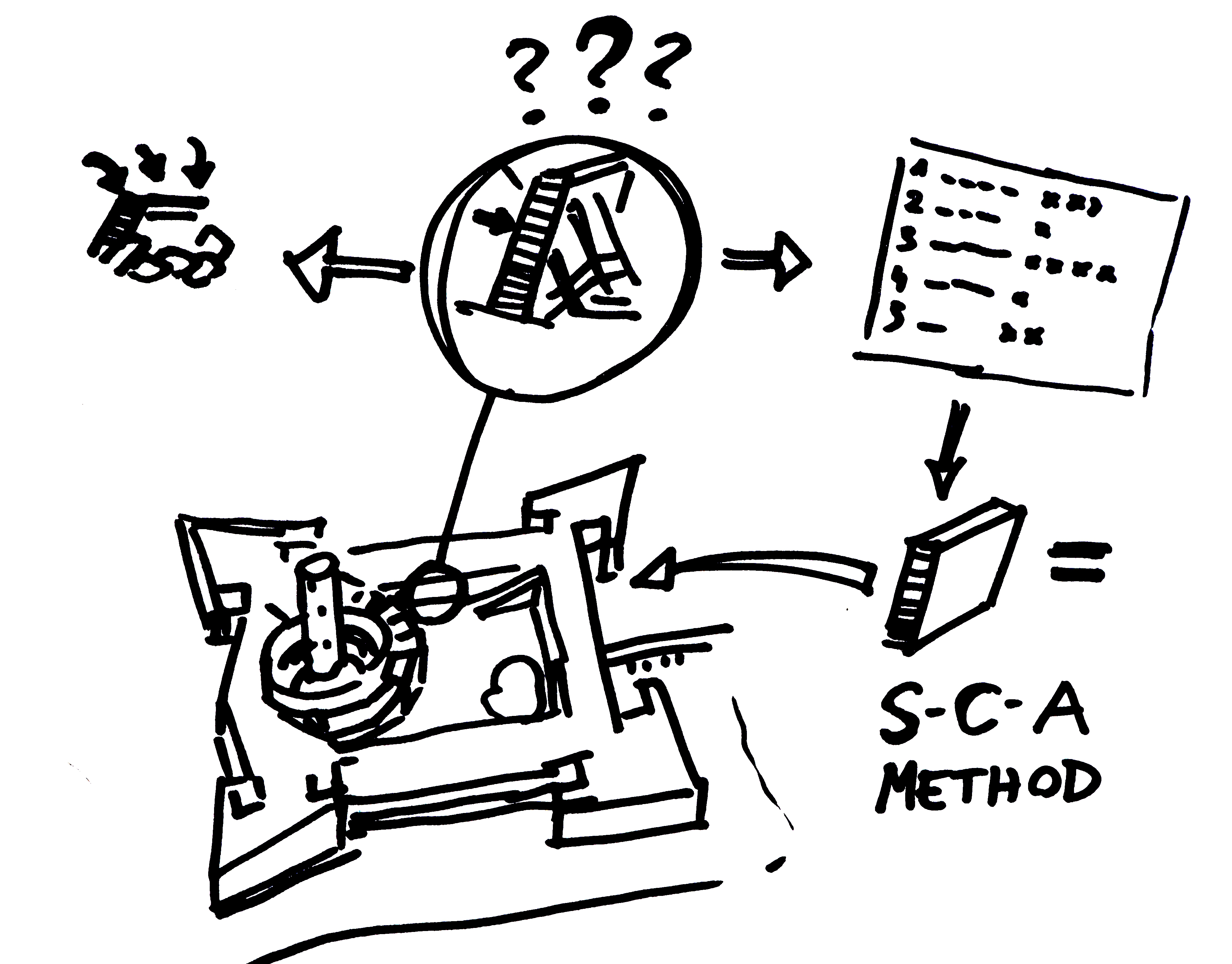
The aim of this paper is to propose a new quantitative criterion for selecting the optimal method of securing and repairing a wall, which takes into account proper structural (technical), conservation and aesthetic conditions. The analyses included here provide an innovative, never-before-used system of assessments (the S–C–A method: Structure–Conservation–Architecture). Notably, this new method may be implemented only as a result of an interdisciplinary analysis of the historical object, in which specialists from different fields of science must cooperate. This approach can be applied to some other cases and it should bring benefits to protect the authenticity of historical structures. The proposed method was applied to the retaining wall in one of the most remarkable examples of historic military engineering in the country and the entire Baltic Sea Region— the Wisłoujście Fortress in Gdańsk, Poland. Several methods of structure stabilization were considered. For each of them, in order to compute to determine the displacement of the wall and its stability, numerical analysis was carried out by the two-dimensional explicit Finite Difference Method, using the FLAC2D software [
45].
2. The Structure–Conservation–Architecture Methodology
The S–C–A (Structure–Conservation–Architecture) methodology has been developed by the authors in order to determine the optimal technology to repair historic buildings. The idea of comparing factors from different fields of knowledge (engineering, architecture, conservation) was based on the theory of sustainable development that was invented for keeping the balance between economic, social (including cultural) and environmental costs of “progress”. It must be mentioned that current literature about cultural heritage in the context of sustainability is focused on landscape values, transport or touristic traffic issues [
46], underestimating the relations between economic pressure and preserving the authenticity of the monument. Therefore, the presented new S-C-A method is focused on preparing a list of proposed technologies and evaluating the influence on the authentic substance, structure and aesthetics of the monument. Comparing such different fields of heritage protection is possible thanks to implementation of numerical factors, which allows evaluation of the grade of intervention in historical substance of historic objects and their neighborhood. Although numerical evaluation could never fully replace interdisciplinary analysis, it might be helpful for the decision makers (e.g., officials in heritage office) in choosing the optimal technology in relatively straightforward cases.
The final evaluation (
Ee) of each method assessed is determined by the formula:
where:
mr—risk factor;
ms—structural score;
mc—conservation assessment;
ma—architectural score.
Risk factor (mr) depends on geotechnical and hydrological conditions, quality of drilling machines, qualities and experience of the drill operators and reliability of the applied reinforcement technology. Its maximum value is 1.0. In order to save space, the risk evaluation has been skipped in this case (in the paper).
The structural score (
ms) must be assigned to a failure mode. Generally, depending on the structural element, different mechanisms of destruction can take place. However, the most important is the critical one. In the case considered, the wall deflection was assumed as the critical one. The structural score is calculated by the formula:
where:
ms—structural score, represents effectiveness of stabilization methods compared to displacement;
u—displacement (cm).
The structural score (
ms) was based on the Polish Standards [
47], which rate the effectiveness of a given method on a scale from 0 to 1; value
ms = 1 corresponds to full safety. Normal wall deflection should be no larger than 0.6 cm/m, which means that
umax = 5.0 cm for the entire height of the wall. It was assumed that this value corresponds to 100% safety (
ms = 1). The current wall deflection (about 15 cm) corresponds to the emergency condition, i.e., 0% safety (
ms = 0).
The conservation assessment (
mc) is defined as the preservation degree of the authenticity of monuments by the following formula:
where:
Vwd —volume of disturbed authentic historic wall;
Vw —volume of authentic historic wall;
Vsd—volume of disturbed authentic soil covering the wall;
Vs—volume of authentic soil covering the wall in impact area.
The preservation degree of the authenticity of monuments is determined by the average of two values, in line with Formula (3). The first value (Vwd/Vw) is a ratio of volume Vwd of disturbed authentic historic wall altered by the application of a given technology (e.g., borehole) to the total volume Vw of authentic historic wall. The second (Vsd/Vs) is the ratio of the volume of disturbed authentic soil covering the wall Vsd by applied technology or archeological excavation to the volume of authentic soil Vs. Because the reversibility of the materials is almost always contrary to the protection of the historical substance (instead of the shape), the authors decided that the spatial indicators illustrating the transformation of the original monuments should be an adequate method of describing the scale of changes. Moreover, they might be easily adopted in the proposed formula.
The architectural (
ma) score is based on the degree of the covered surface by the new designed structural solution to the total wall surface described by the formula:
where:
Ad—covered surface of the wall or/and its neighboring area;
At—total surface area of the wall above the ground.
The surface covered by the new designed structural solution is determined by the scale of the impact on the area around the monument, in line with Formula (4). The value (Ad/At) is a ratio of the covered surface area Ad of the wall (or its neighboring area) altered by the application of a given technology (e.g., scaffolding) to the total surface area At of the wall above the ground.
The authors decided to scope their research to a single case study because they wanted to build a comparable evidence base of popular repairing techniques. That is the reason why the authors avoided analyzing the repairs in different monuments, which always was based on individual studies. Although such a strategy would have been preferable in most heritage studies, it does not allow for testing the S–C–A method. Therefore, the methodology described above was applied in the evaluation of the repair technique of the retaining wall in the Wisłoujście Fortress.
3. Research Object
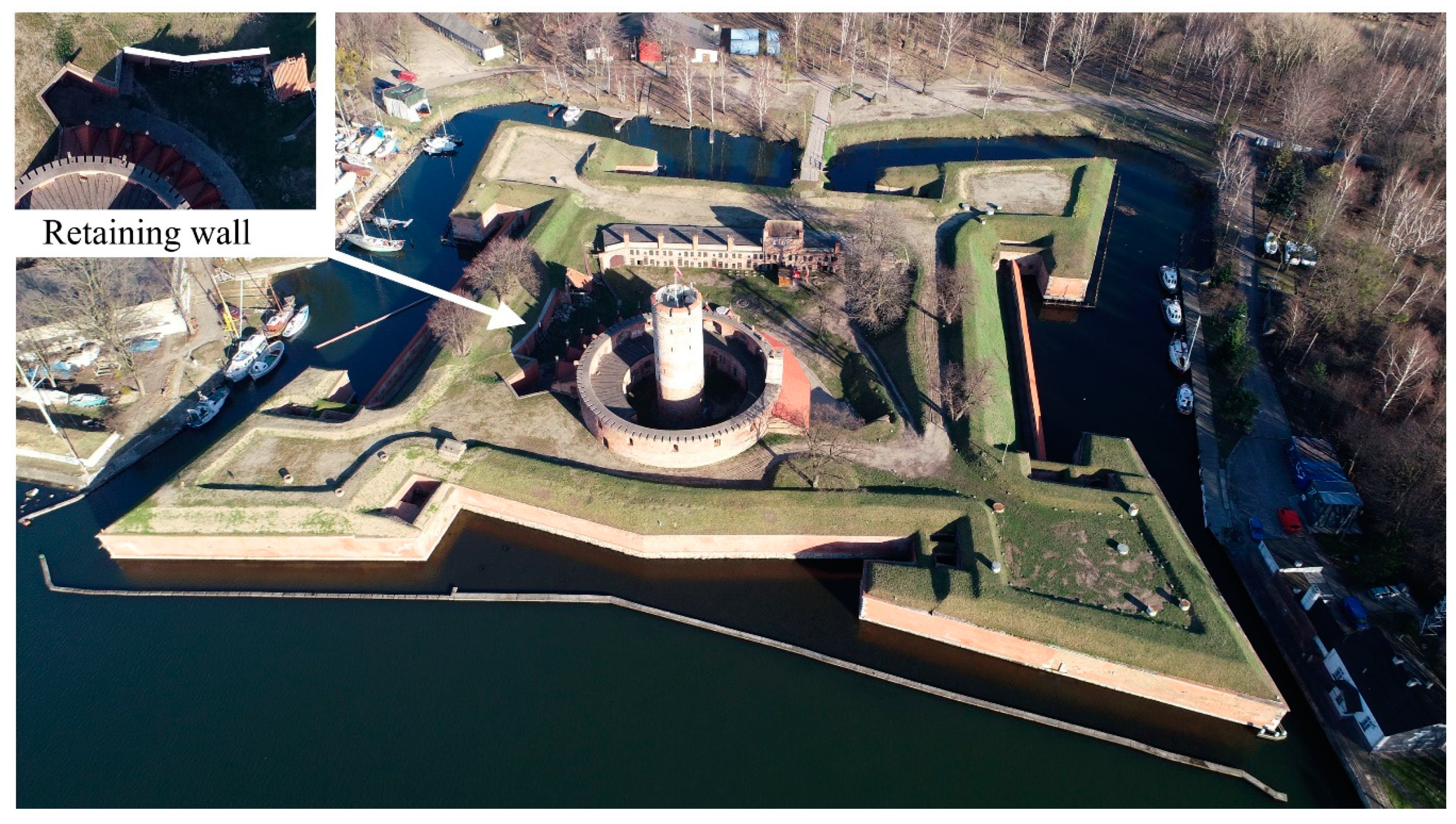
The Wisłoujście Fortress (
Figure 1) is an example of well-preserved fortification and hydrotechnical engineering from the Middle Ages and early Modern Era. The President of the Republic of Poland decided in 2018 to award this monument the highest level of protection by including it on the Polish Heritage List as a “Historic Monument” [
48].
The retaining wall—the main subject of this paper—was primarily built as a part of another structure, the lieutenant’s quarter, used later as an auxiliary building [
49]. The ground-floor building, erected on a rectangular plan, was situated by the northern curtain wall of the Fort Carré in the first half of 17th century.
Unlike the main barracks, which were located in the eastern wall of the fort and covered by ground, the building mentioned was covered by a steep roof reaching over the curtain wall. This was probably the reason why this construction was demolished in early 19th century, either during the Napoleonic Wars, when the fortress was besieged twice in 1807 and 1813, or shortly after. The northern part of the demolished building was turned into the retaining wall, although it had never been designed for that purpose (
Figure 2). In the second half of the 19th century, when military authorities decided to strengthen the structure of the Fortress, an external layer of bricks was added to the wall. It also became necessary to build a buttress of the wall which was situated by the west side of the demolished building. The next alterations or works were not conducted in the area of the retaining wall until the removal of neglected greenery in the 1990s. It is likely that the use of heavy machines made it necessary for the deflected wall to be subsequently supported by two wooden buttresses.
The alterations to the wall described above contributed to its current state of deformation. It is evident that no basic stability requirements for such wall—neither overturning about its toe nor sliding along its base—are met (
Figure 3C). However, after demolition of the auxiliary building at the beginning of the 19th century, the retaining wall did not collapse. The actual stability is a result of the combination of the following: (1) the spatial rigidity of the wall’s structure due to its irregular shape (
Figure 1), (2) adding of the buttress which supported the wall and (3) the real active pressure decreased due to the wall deformation that had already occurred in the past.
The impact of greenery might be considered as another hypothetical reason for the deflection of the wall. There were wild bushes growing on top of the curtain wall, which might have caused some structural failure [
50,
51]. Although the whole construction was kept in good condition until the 1930s, the greenery was not pruned after the Second World War. In any case, the excavations in 2016 did not confirm whether the roots could have harmed the retaining wall.
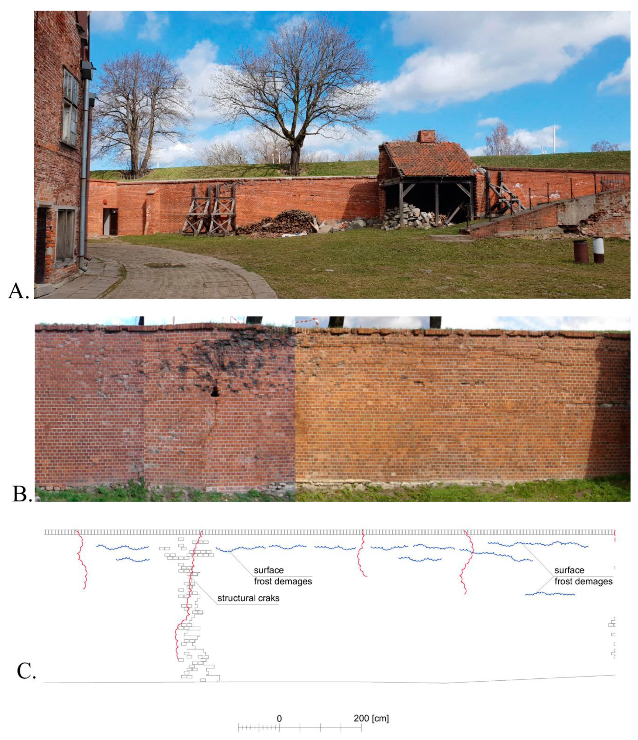
Because the wall did, in fact, resist earth pressure for about 130 years, numerous vertical cracks have appeared on the surface of the wall, approximately within 0.5–2.3 m from each other (
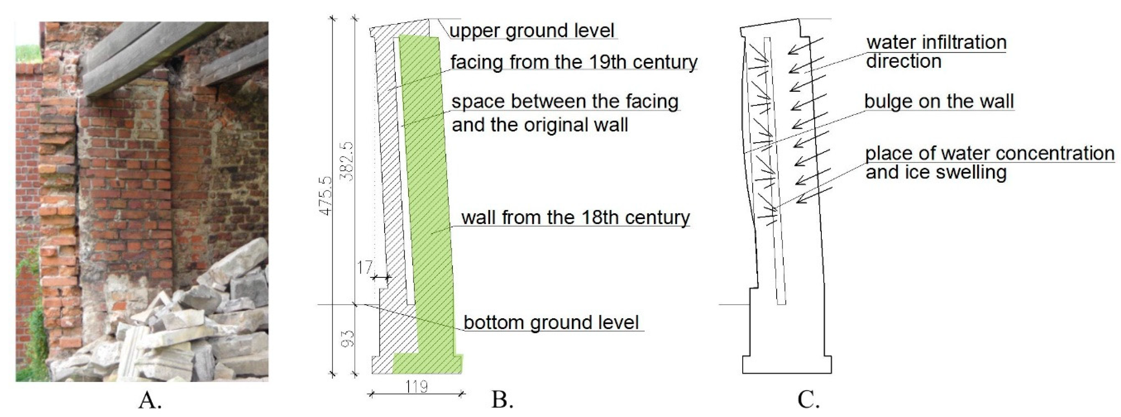
Figure 4). There is also surface freeze–thaw cycle damage visible on the wall, which could, to an untrained eye, look like cracks. Since the second half of the 19th century, two significant series of repairs have been carried out. The first was the addition of a 25 cm-thick brick siding layer and the second one was a buttress. The new facing (
Figure 3A,B and
Figure 5) was added without re-walling, which, paradoxically, led to deterioration of masonry over time: a crevice that developed between the new and old walls collected water (
Figure 4). At low temperatures, the water froze, bursting the wall and causing bulges in its upper part (150 cm from the top of the wall), which increased its deviation from the vertical (see
Figure 3). In 2016, the deviation from plumb amounted to approximately 15 cm.
In conclusion, the primary reason for structural failure of the wall is associated with its structural characteristics (
Figure 4). However, some cracks observed nowadays may have developed accidentally, due to pressure increase during the removal of greenery. Finally, the retaining wall had lost its stability in the past and had to be strengthened by the temporary wooden buttress (
Figure 4A). Therefore, it is impossible to confirm whether the inclination has stopped or it is still increasing.
5. Numerical Analysis
The purpose of the numerical analysis was to determine the effectiveness of the selected methods in strengthening and stabilizing the wall. The analysis was performed by the two-dimensional explicit Finite Difference Method (FD), using the FLAC2D software [
45]. This method is an accurate and versatile approach to the analysis of both stability and displacement of retaining walls. It allows for calculating the field of displacement both in the soil mass and in the engineering structures, which are considered as appropriate for the stabilization and strengthening of the wall. Its stability was assessed based on the safety factor F, which is calculated using strength reduction technique fundamentals. The additional advantage of the proposed method is that it makes no assumptions about the failure mechanism—especially for simple geometry. In contrast to the traditional “limit equilibrium” analysis, this method provides a full solution to the coupled stress/displacement, equilibrium and constitutive equations. The calculations were based on the so-called “strength reduction technique” [
52]. Geotechnical studies [
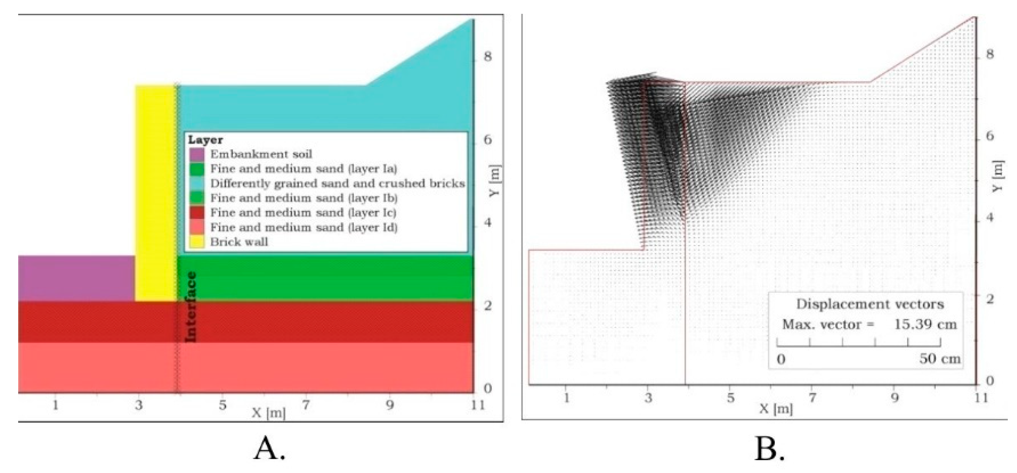
53] have shown that the groundwater level is currently 2.0 meters below the base of the wall foundation. The substratum is composed mainly of fine and medium sand (
Figure 6A), and the earthwork that loads the retaining wall consists of fine sand and brick debris. The soil density index in the rampart body (ID) is 0.2.
Table 1 presents the parameters of soil layers in the calculation model. The diversity of soils in the Ia-Id layers results from their different degrees of compaction, ranging from 0.30 for the layer Ia to 0.70 for the layer Id. On the basis of laboratory tests, the average compressive strength of old bricks was determined to be equal to 15.8 MPa, mortar equal to 0.75 MPa and new ones (from external wall)—equal to 34.1 MPa and 19.3 MPa [
52].
First, the current original state of the wall was examined by the “back analysis” method, i.e., the variant without wall stabilizing measures. The aim was to determine the values of strength parameters (cohesion and angle of internal friction of the soil constituting the earthwork that puts pressure against the wall), for which the measured and calculated displacements of the wall crown would be the same. It means that, by contrast to other parameters determined in the tests, these two strength parameters (i.e., cohesion and angle of friction) are found at the base of calculations using a “trial and error” approach and FLAC2D code. A numerical model and displacement vectors are shown in
Figure 6. Calculated maximum displacement (u) of the wall’s crown was equal to 15.21 cm.
The values of wall crown displacements were obtained by numerical calculations in all the cases, which made it possible to identify the methods meeting the criterion
umax = 5 cm.
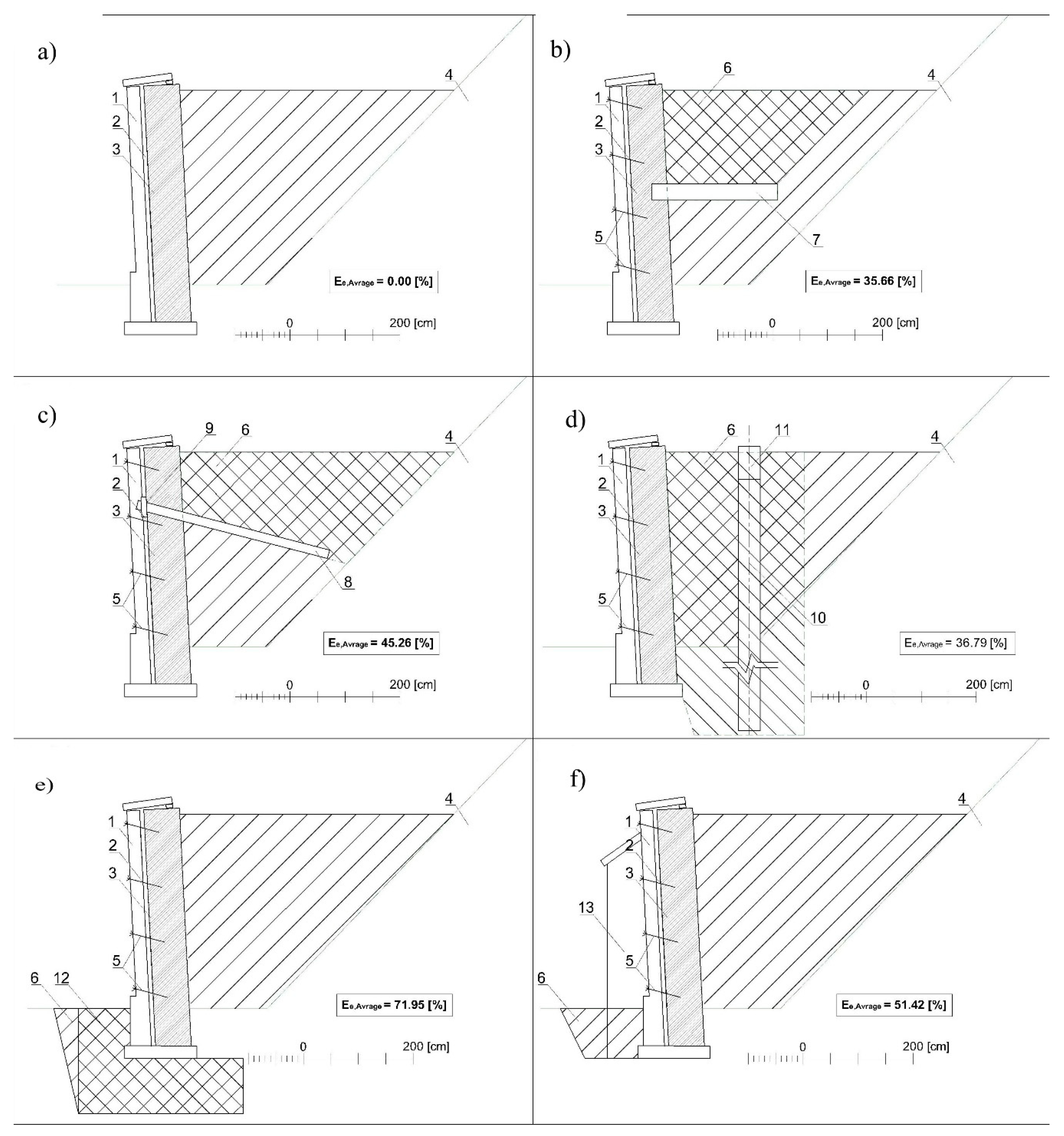
Table 2 provides the maximum calculated displacement values for the stabilization methods assessed in the analysis.
On the basis of the results summarized in
Table 2, the considered stabilization options can be ranked. The diagrams (models) of particular stabilization methods are also presented, including the current (natural) state of the wall.
It should be noted that no experimental verification of the calculation results regarding the influence of each stabilization method is currently possible; no stabilization works were completed so far. Nevertheless, given the carefully determined parameters of the soil and the wall materials in combination with the characteristics of the advanced numerical tool that is the FLAC2D algorithm, the calculation results in all variants are reliable and represent both physical qualities and behavior of the object accurately. The fields of stress and displacement express, precisely, the influence of all stabilization measures and methods. As it can be seen in
Table 2, buttress support turned out to be the most effective stabilization countermeasure. In all stabilization cases, the maximum displacement is significantly lower (in the case of buttresses, by even more than 20 times) in comparison with the displacement of the original wall. It proves the high potential effectiveness of any stabilization method.
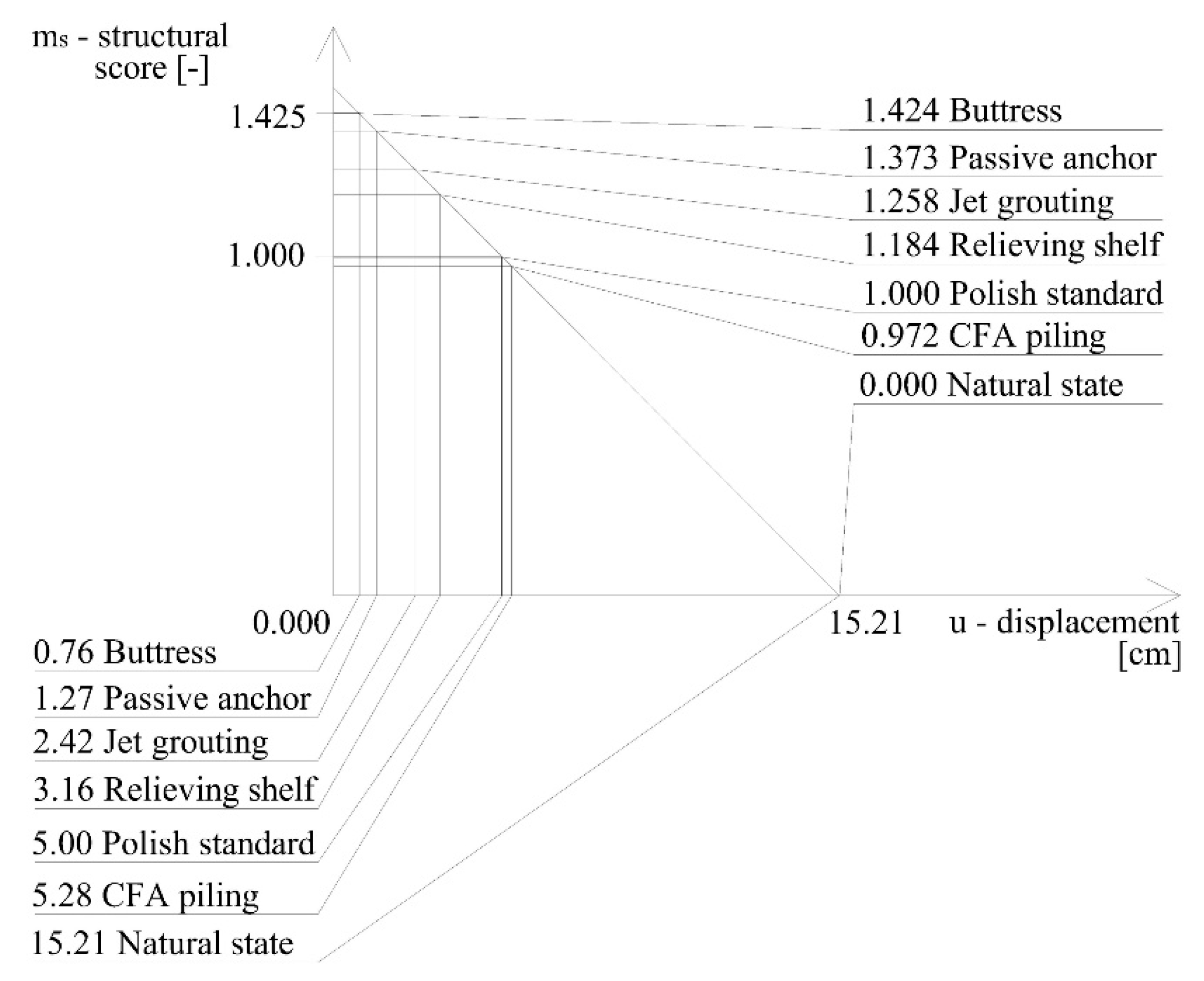
The relationship between the calculated displacement of the wall’s crown and the structural score calculated by (Formula (2)) is presented graphically in
Figure 7.
It is seen in
Figure 7 that the calculated displacement of the wall’s crown in the case of the relieving shelf is 3.16 cm and corresponds to 18.4% above the required level of safety, whereas the displacement of the wall’s crown for buttress is 0.76 cm and corresponds to 42.2% above the required level of security and so on.
6. Evaluation of the S–C–A Method
The partial and final results of the S–C–A methodology are summarized in
Table 3. There are also relevant volume or area values included here, appearing in Formulas (3) and (4), as well as particular, individual assessments. The presented data allow comparing the results which were achieved for three different fields of heritage protection: structural, conservational and aesthetical.
According to the structural aspect (
ms), it is proved that the best methods of repairing historical wall are buttress, passive anchors and jet grouting. However, some of them may cause too much integration in the authenticity of the monument, which degrades its heritage value. In spite of the constructional advantages, jet grouting and relieving shelf are the least acceptable methods of stabilization because of the scale of integration in the historical substance of the wall (see
Table 3). It impacts the final evaluation (
Ee). It is worth noting that buttresses achieved relatively the worst score in the ranking of aesthetic values (
ma) but were the mostly accepted method of strengthening the historic construction in previous eras. What is more, a similar structure was erected for the analyzed wall in the 19th century and its impact on the authenticity of the monument was very limited. On the other hand, minimizing the space between new buttresses may cause deterioration of the aesthetical factor.
The S–C–A method allows for understanding how different modes of repairing the historic construction may influence its protection. Consequently, there is no one proper method of strengthening the wall because each of them devastate some part of it. Comparison of each partial score shows that the optimal method is strengthening the wall with buttresses, but passive anchors are acceptable as well. The highest ranking achieved by this method resulted, for the most part, from its high structural (
ms) and conservation (
mc) score, due to the most favorable ratio of the volume of disturbed soil (
Vsd) to the volume of the authentic soil (
Vw) covering the wall. The second and fourth column of
Table 3 represent the values of the altered surface area of the wall and the volume of soil to be excavated for each of the assessed methods. The conservational, structural and, particularly, architectural assessments presented in the eighth, ninth and eleventh column of the table are objective. Subsequent columns show the results of calculations assuming different values of impact factors representing the relative importance ascribed to the conservational, structural and architectural aspects.
It seems that the highest value of the risk factor mr corresponds to the relieving shelf and the lowest mr corresponds to jet grouting. However, this factor should be evaluated on the basis of more precise research, which is not the subject of this paper. In the following calculations, the risk factor mr = 1.0 is assumed.
Some disadvantages of certain technologies should be mentioned as well. In the case of CFA piles, a problem may arise from the limited access of the drilling machine, whose weight, depending on the model, ranges between 8 and 20 t. It is therefore necessary to check and secure the route of the machine to the working zone and to evaluate the wall conditions during its operation. Additional pressure on the soil resulting from drilling is another difficulty associated with the use of CFA piles. A disadvantage of jet grouting is the risk of collapse of the grouted zone, caused by a low strength of the mixture of organic soil and cement mass. It is vital to use appropriate pressure and density of the injected mixture; incorrect selection of these quantities may result in the formation of voids. Furthermore, a large amount of liquid spoil created during jet grouting has a negative impact on the quality and aesthetics of the construction site. Finally, the relatively large spacing (3 m) of buttresses can be an issue: the zones between them lack any stabilizing element, so the wall sections between the buttresses may still become unstable.
7. Conclusions
The authenticity of historical buildings is thought to be so precious because when once destroyed, they will never be reconstructed. Thus, material heritage could be treated as a non-renewable resource. Finding the right balance between keeping monuments intact and present necessities is, however, an open question. Seeking the proportions between factors determined by different fields of science makes the S–C–A method resemble the theory of sustainable development. Legal framework requires an administrative act—a decision by conservation officers who must take into account conservational, architectural and structural factors. Sometimes, the authorities seek help from experts, but in the end, the decision is theirs, and as a consequence, the outcomes vary due to differences in the officers’ knowledge and experience. Therefore, the proposed method might be applied to improve the relations between stakeholders involved in repairing the historical structures (engineers, architects and conservation officers). It would help not only in the communication process but also in preselecting the best solutions. Although the authors are aware of the significance of personal expertise, there is a need for a more verifiable approach, an evidence-based method for evaluation of interventions in historical structures.
That is the reason why this paper’s focus is on the retaining wall instead of the entire Fort Carré or group of different monuments. As the authors proved, the wall is representative of the practical problems that typically arise with monument conservation. Even though the different methods of stabilizing walls could be ranked (
Table 3), selection of the most appropriate one might be challenging. This is mainly because the final conservation assessment and, above all, the architectural (aesthetic) assessment are, to some degree, subjective, even if quantified (
mc; ma). In contrast to the strictly objective structural assessment—based on the displacement criterion—they rely on non-measurable criteria, such as the quality of expertise and experience of the actors involved. In addition, certain solutions may encounter resistance from a conservation officer, who may have limited knowledge of engineering technologies. Nevertheless, the approach proposed in this paper may serve—at least in some cases—as an auxiliary tool in decision-making. Optimization of stabilization systems in the protection of cultural heritage must meet additional requirements, such as conservation and/or aesthetic (architectural) ones. Before they are used in the optimization procedure, they should be subjected to a quantitative, possibly objective, assessment. The issues pertaining to the costs of renovation of historical buildings are of secondary importance. In these cases, classic, i.e., structural or economic, optimization needs to be significantly modified.
The proposed S–C–A method has been checked in the case of the retaining wall and, undoubtedly, needs more complex tests in further research. This paper, however, aimed to present a new proposition about the multi-criteria technique of selecting the solution of repairing basic monuments. Although professional interdisciplinary research into historical buildings must be undertaken in all instances of emergency engineering interventions before designing an actual solution could even commence, the presented algorithm might be useful for engineers in choosing the best variant of repair, and it helps in communication between different stakeholders.


