Suitability of Remediated PFAS-Affected Soil in Cement Pastes and Mortars


Institute for Frontier Materials, Deakin University, 221 Burwood Hwy, Burwood 3125, Australia
*
Author to whom correspondence should be addressed.
Sustainability 2020, 12(10), 4300; https://doi.org/10.3390/su12104300
Submission received: 17 April 2020
/
Revised: 12 May 2020
/
Accepted: 19 May 2020
/
Published: 25 May 2020
Abstract
:Australia and many other parts of the world face issues of contamination in groundwater and soils by per- and poly-fluoroalkyl substances (PFAS). While the pyrolytic treatment of contaminated soils can destroy PFAS, the resulting heat-treated soils currently have limited applications. The purpose of this study was to demonstrate the usefulness of remediated soils in concrete applications. Using heat-treated soil as a fine aggregate, with a composition and particle size distribution similar to that of traditional concrete sands, proved to be a straightforward process. In such situations, complete fine aggregate replacement could be achieved with minimal loss of compressive strength. At high fine aggregate replacement (≥ 60%), a wetting agent was required for maintaining adequate workability. When using the heat-treated soil as a supplementary cementitious material, the initial mineralogy, the temperature of the heat-treatment and the post-treatment storage (i.e., keeping the soil dry) were found to be key factors. For cement mortars where minimal strength loss is desired, up to 15% of cement can be replaced, but up to 45% replacement can be achieved if moderate strengths are acceptable. This study successfully demonstrates that commercially heat-treated remediated soils can serve as supplementary cementitious materials or to replace fine aggregates in concrete applications.
1. Introduction
On a global scale, concrete is the single most used man-made material, amounting to a usage of 3 tonnes per person per year [1,2,3]. The cement and concrete industry emits about 5–8% of the total global CO2 output [4,5,6]. Numerous options are available to reduce the carbon footprint of the sector (e.g., avoid or limit concrete use where possible, substitute Portland cement with low CO2 supplementary cementitious materials (SCMs), improve efficiencies of cement manufacturing plants, use alternative fuels in kilns, substitute clinker/aggregate, improve concrete durability, etc.) [7,8]. All of these strategies, or combinations of them, are appropriate and should be utilised whenever possible.
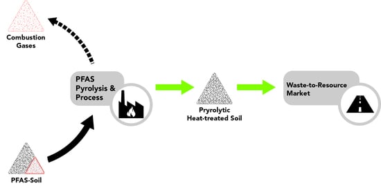
Contamination by per- and poly-fluoroalkyl substances (PFAS) of the natural environment, as well as purpose-built infrastructure, is a worldwide problem impacting many communities [9,10,11,12,13,14,15,16,17]. In this study, an overview of trials is given where cement and fine aggregate replacements were sourced from heat-treated remediated soils that had been previously impacted by PFAS. The heat-treatment, consisting of a two-phase pyrolytic process (the technology owned by Renex Op Co Pty Ltd., Dandenong South, Australia), both destroyed the PFAS and partially activated (i.e., calcined) the clay component of the soil.
Currently, there is a worldwide shortage of both fine and coarse aggregate for use in concrete [18,19,20,21,22]. In particular, Melbourne (due to major projects) faces severe shortages of suitable fine aggregate. Melbourne has the additional problem (like many major cities) of PFAS contamination in soils and sediments (as well as surface and ground waters) in which major infrastructure projects are being undertaken. In the West Gate Tunnel project alone, 4000 tonnes of PFAS-contaminated soil has been stockpiled [23]. Furthermore, heat-treated soils are classified as industrial waste and therefore need to be sent to landfills at considerable expense unless they can be converted into a resource. While direct disposal in landfills may be an easier option, it uses valuable landfill volume, precludes the possibility of using the material as a resource and therefore unsustainably depletes more of the limited supply of virgin sand, cement and aggregate. In addition, when disposed in landfills, co-contaminants can become an issue [24,25]. In contrast, co-contaminants can be locked up in the cementitious matrix [26], thereby avoiding further exposure of the environment. By value-adding remediated soils as components in cements, mortars and concretes, one has the ability to provide economic sustainability to the remediation industry. At the same time tens of thousands of tonnes of useful material can be utilised that otherwise would be disposed in a limited number of licensed landfills, potentially subjecting humans and the environment to long term exposure.
Heat-treated soils containing sufficient amounts of clay minerals can potentially be used as supplementary cementitious materials. Their pozzolanic activity is dependent on the initial mineralogy and activation temperature, and their “shelf life” requires maintaining them in dry state [27,28,29,30,31,32,33]. The reactivity of kaolinitic clay is significantly greater than any 2:1 layer clay minerals [34]. When activating clay minerals by heat-treatment, the temperature must be high enough to increase the structural disorder of the clay minerals present by dehydration and dehydroxylation, but not so high to cause the recrystallisation of mullite. Keeping the heat-activated clay dry subsequent to treatment is important because metakaolin (calcined kaolinite), for example, interacts with water [35] and loses its cementitious properties via rehydration.
There are many benefits of employing the pozzolanic activity of calcined soil as SCM in cement or concrete applications. Arguably, the most important is a reduction of the considerable carbon footprint of cement manufacture: clinker is kilned at ~1500 °C vs. soil pyrolytic treatment, at ~550–650 °C. Any cement clinker offset by calcined soils necessarily leads to an increased energy efficiency of cement manufacture. SCM-clinker blends have been shown to provide comparable strengths at lower ordinary Portland cement (OPC) contents and also result in superior concrete durability, reduced heat of hydration and hence reduced risk of early age thermal cracking [36,37,38,39]. By considering calcined soils as a source of fine aggregates, the currently experienced shortage of aggregates can be eased, particularly where the fine aggregate replacement (FAR) is sourced near, or indeed from, major projects. This study provides the basis for a successful use of reclaimed PFAS-affected soils in cements, mortars and concretes, particularly as replacements of fine aggregates in mortars and concretes, but also as supplementary cementitious material in cements. When studying the suitability of the heat-treated soils as FAR, mortars were chosen initially to enable a clear distinction between the soil fine aggregates and conventional concrete sand.
2. Materials and Methods
Mixes of cement pastes (mixture of cement and water) and mortars (mixture of cement, water and fine aggregates) incorporating heat-treated soils as either SCM or as FAR were prepared, and the fresh and hardened properties of the mixtures were investigated. Ordinary Portland cement with the properties listed in Table 1 (and conforming to Australian Standard AS3972-2010 [40]) was the primary binder used. All mixes were prepared in a 20 L mortar mixer according to ASTM C305 [41] and the fresh mixtures were casted in 75 × 75 × 75 mm cube moulds. The compressive strength measurements were conducted on 5 samples with a semi-automatic compression-testing machine as per ASTM C109 [42]. Reference samples were tested twice (i.e., a total of 10 samples on two different days) to make sure variations due to changing ambient conditions (e.g., relative humidity, temperature, etc.) were negligible. The slump values of some of the fresh mixtures were determined according to Australian Standard 1012.3.1 [43]. After one-day curing in the moulds, all samples were demoulded and placed in a lime-saturated bath as per Australian Standard 1012.8.1 [44] for a further 27-day curing.
2.1. Soils
A pyrolytically heat-treated PFAS-affected soil was provided by Renex Op Co Pty Ltd., Dandenong South, Australia (Renex). PFAS are a large group of fluorinated hydrocarbons currently listed as substances of environmental concern in Australia. Contaminated soils which arrive at Renex are often co-contaminated with PFAS, hydrocarbons, various types of pesticides and other co-contaminants. A two-phase pyrolytic treatment [45] destroyed the organic contaminants in the soils but resulted in the loss of many soil properties (mineral transformation and total sterilisation). During the process, the contaminated soils travel through a rotary kiln at temperatures of ~550–650 °C with a typical residual time of about one hour. Being a pyrolytic process, all oxygen is purged from the waste stream with nitrogen gas. Any non-volatile organic materials are carbonised during this process. The out-gas stream containing volatilised PFAS (and co-contaminants) is then fed into a secondary pyrolytic chamber and combusted at ~1200 °C for final destruction. Post heating-stage scrubbers (wet and dry system), filters and an activated carbon bed collect and remove all CO2, fluorine and other associated non-organic, and potentially acid-producing, gases from the waste stream. In recent tests, all PFAS present in PFAS-doped soil was removed to below detection limits when Renex’s two-phase pyrolytic method was used.
On exiting the treatment process, the treated soil is generally sprayed with water for cooling and dust control then stockpiled. Most soils for this study were collected from the top 0.3 m of the stockpile and used predominantly as fine aggregate replacement. For studies on using the heat-treated soil as supplementary cementitious material (SCM), a size-fractionated portion of the collected sample was reactivated by heating to 750 °C for 2 h in a laboratory muffle furnace. In some tests, the heat-treated soil was collected from the plant in a dry state (i.e., without sprinkling it with water) and similarly used (i.e., as SCM).
2.2. Analysis
Fourier transform infrared (FTIR) spectroscopy and X-ray powder diffraction (XRD) techniques were applied to crushed and then milled (McCrone XRD Mill; milled for 6 min using agate grinding elements) samples. FTIR measurements were conducted with a Perkin Elmer Frontier spectroscope in the range of 650–4000 cm−1, 4 cm−1 resolutions and 64 co-added spectrum per measurement. The milled samples were pressed against the diamond-attenuated total reflectance (ATR) probe using a pressure arm (relative force ~100 unit). XRD patterns were collected with a PANalytical X’Pert Powder diffractometer (Cukα; λ = 0.15406 nm) in the range of 6.7–70° 2θ, with a step size of 0.01313° and 0.49 s time/step, on front-pressed sample mounts. As a reference sample, a kaolin-rich alluvial clay (>80% kaolinite), calcined at 750 °C for 2 h, was also studied.
Particle size distribution was measured with a series of stainless steel sieves with the following aperture sizes: 26,500 μm, 13,200 μm, 9500 μm, 6700 μm, 4750 μm, 2360 μm, 600 μm and 75 μm, following ASTM D6913/D6913M–17 [46].
2.3. Fine Aggregate Replacement (FAR)
Fine aggregates were replaced with sieved heat-treated soil at replacement rates of up to 100%. Specific gravity and water absorption values of the FAR and reference concrete sand were measured according to AS 1141.5 [47]. The FAR component of the remediated soil were the sieved fractions (75 µm to 2.36 mm with 2.9% water absorption and 2.2 specific gravity of the sieved pyrolytically treated soil), proportioned to match the fine aggregate used in the reference mixes. For all mortar mixes, the very fine (<75 μm) and very coarse (>2.36 mm) fractions of the aggregates were excluded to (i) minimise any strength gain due to cementitious activity from the <75 μm phases (where cementitious properties are most likely) of the treated soil, (ii) eliminate reduced workability due to the presence of fine particles in large quantities and (iii) eliminate the effects of coarse aggregates (>2.36 mm).
Mortar mixes were prepared with the inclusion of fine aggregates purchased from a local supplier marketed as “concrete sand” (washed sand) with a specific gravity of 2.54 and water absorption of 0.7%. We selected mortars rather than concretes because in mortar mixes the influences of fine aggregates on the various fresh and hardened properties are more pronounced. The water to binder ratio for all mixes was 0.45. Based on some preliminary research, the reference mortar mix with 0.45 water to cement ratio gave good consistency and workability. In the mortar mixes where a high percentage of heat-treated soil FAR was used, a polycarboxylate-based high-range superplasticiser (~0.45–2.38% by weight of cement) was used. For all mortar mixes a 1:2 cement to fine aggregate ratio was used. Mix designs were based on saturated surface dry (SSD) conditions.
2.4. Supplementary Cementitious Material (SCM)
To investigate the usefulness of heat-treated soil as a supplementary cementitious material (SCM), we started by analysing the effect of the as-received hydration state of the soil. The as-received or lab-calcined soil (see below) was milled for 8 h at 400 RPM in a planetary ball-mill to obtain 100% passing 75 μm. This milled product was then used to replace various percentages (up to 45%) of the binder. Additionally, paste mixes were prepared with 15% SCM content from “as-received”, “oven dried”, “calcined” and “dry received” sources. The “as-received” sample was collected from the treated stockpile of the Renex pyrolysis plant. In addition to being wet during the dust control steps, the stockpile was exposed to various weather conditions (e.g., rain, sunlight, wind, etc.). The samples that ultimately arrived to our research facility corresponded to an air-dry but previously wet (rain) condition. A portion of the “as-received” sample was then dried in a laboratory oven at 110 °C for 16 h to eliminate any residual moisture in the soil and to obtain an “oven dried” sample. Another portion, referred to as “calcined”, was heated to 750 °C for 2 h in a closed container to reactivate (i.e., calcine) the clay component of the sample. Recommendations by Scrivener 2019 [34] (e.g., optimal calcination temperature of ~700–800 °C, 1–2 h residual time, etc.) were followed in the calcination process. The “dry received” soil corresponded to samples collected directly from the rotary kiln, prior to normal processing (i.e., spraying with water). The properties of the paste and mortar mixes are detailed in Table 2.
3. Results and Discussions
3.1. Compositional Differences
The phase compositions of the commercially available concrete sand and the calcined soil at 750 °C as determined from XRD are shown in Figure 1. Not surprisingly, the reference concrete sand contained predominantly quartz, but also a small amount of feldspar and trace amounts of mica. The treated calcined soil was more complex and was dominant by quartz. Also present were minor amounts of metakaolin (from the calcination of kaolinite), feldspar (mainly albite), illite, calcium carbonate (calcite) and calcined mica (mainly biotite and muscovite). The presence of metakaolin and partially calcined illitic clay indicated that the calcined soil would show pozzolanic activity (illites reach complete calcination at higher temperatures (~950 °C) [48]). The overall higher background of the calcined soil’s XRD trace, most importantly between 15 and 30 2θ°, indicates a greater content of amorphous phases in the heat-treated soil compared with that of the concrete sand [49].
Secondly, the XRD phase composition of the “calcined” soil was compared with that of the “dry received” soil (Figure 2). Both soils contained essentially the same phases (e.g., quartz, kaolinite, metakaolin, illite, feldspar, mica and calcite). Furthermore, the highly similar baselines of the calcined and dry received soils indicate similar amorphous contents. However, the collected XRD pattern indicated a greater amount of kaolinite (diffraction peaks at ~11.6, ~19.8, 23.7 and ~25.4 2θ° [50,51,52]) and, correspondingly, a lower metakaolin (~8.9, 23.6 and 31.4 2θ° [53,54]) content in the dry received soil, which emphasises the importance of an adequate calcination temperature. In this instance, the lower temperature used in the pyrolysis plant (~550–650 °C compared to 750 °C in the lab furnace) resulted in greater residual kaolinite content and only partial calcination of the kaolinite [34]. Moreover, the greater illite content (~10.1 and 35.6 2θ° [51,52,55]) of the dry received soil indicated that less illitic phases were calcined compared to those of the calcined soil. The overall lower calcined clay content of the dry received soil compared to that of the calcined soil forecasts a correspondingly lower pozzolanic activity as well.
The FTIR spectra of the reference concrete sand, the calcined soil and the dry received soil (Figure 3) confirmed the presence and dominance of quartz (~1163 cm−1 → Si-O-Si stretching, ~1057 and ~1081 cm−1 → Si-O stretching, ~796 cm−1 → Si-O symmetric stretching, ~777 cm−1 → Si-O symmetric bending, ~695 cm−1 → Si–O of SiO4 symmetric bending) [56]. One difference between the reference sand and the soils is that the spectrum of the dry received and calcined soils exhibits a shoulder (~673 cm−1) on the Si-O band at ~695 cm−1, which likely indicates the presence of iron-oxide phases [57,58].
To investigate this further, an as-received soil sample was calcined in an open container rather than a closed container (inset, Figure 3). As anticipated, the aerobic calcination resulted in a more intense peak at ~673 cm−1 due to the greater amount of iron-oxides (i.e., more oxygen was available for forming such phases). By comparing only the dry received soil and the calcined soil (closed container case), this shoulder is less intense for the dry received soil. The composition of the atmosphere in the rotary kiln was more anoxic (produced by purging with nitrogen gas), whereas in our laboratory furnace the anoxic environment was created using a closed system (i.e., while sealed, there was initially some oxygen present). Non-surprisingly, purging is a more effective way of eliminating oxygen and the formation of various oxides.
Another focus area of the collected FTIR spectrum is the range of 800–1000 cm−1, where some differences between the various samples in the FTIR spectra were also observed. It appeared that the reference sand had no peak or shoulder within this range, but the dry received soil showed a very minor shoulder and the calcined soil a more pronounced shoulder. When kaolinite transforms to metakaolin during calcination, the following chemical reaction (Equation (1)) takes place [36,59]:
Al2Si2O5(OH)4 → Al2Si2O7 + 2 H2O
The presence of the shoulder was probably related to the different coordination states of the Al in kaolinite and metakaolin (Al coordinates with more oxygen in metakaolin compared to that in kaolinite) [60]. Consequently, the greater electronegativity (from the extra oxygen atoms) resulted in a shift and shoulder formation (around 925 cm−1) of Si-O-Si stretching at ~1057 cm−1. Hence, the given shoulder could be a good indicator of the presence of metakaolin and might reveal information on the amount of metakaolin phases. Thus, the calcined soil used had more metakaolin compared to the dry received soil, which confirms the XRD results presented earlier.
Overall, the high quartz content of the heat-treated soil indicates its suitability as fine aggregate replacement. Moreover, the presence of metakaolin and calcined illite indicates the potential for using (at least a portion of) the soil as a supplementary cementitious material (i.e., pozzolana). The two listed options were investigated in detail, and the main outcomes are discussed below.
3.2. Replacing Sand with Heat-Treated Soil in Mortar Mixes
3.2.1. Particle Size Distribution
For a fine aggregate replacement application, we considered the particle size distribution (PSD) a key parameter. Consequently, the PSD of the heat-treated soil was measured following ASTM D6913/D6913M–17 [46]. In Figure 4, the average of three measurements is plotted and compared with the PSD of the commercially available concrete sand also used in this study. The cumulative curves in Figure 4 clearly show that the two materials had similar portions within the 0–2360 μm particle size range (~71% vs. ~88%), although the heat-treated soil contained more fines (~49% vs. ~25% within the range of 0–600 μm). Furthermore, the treated soil contained more of the coarse particles (> 2360 μm) compared to the concrete sand (~29% vs. ~12%).
3.2.2. Fresh Properties
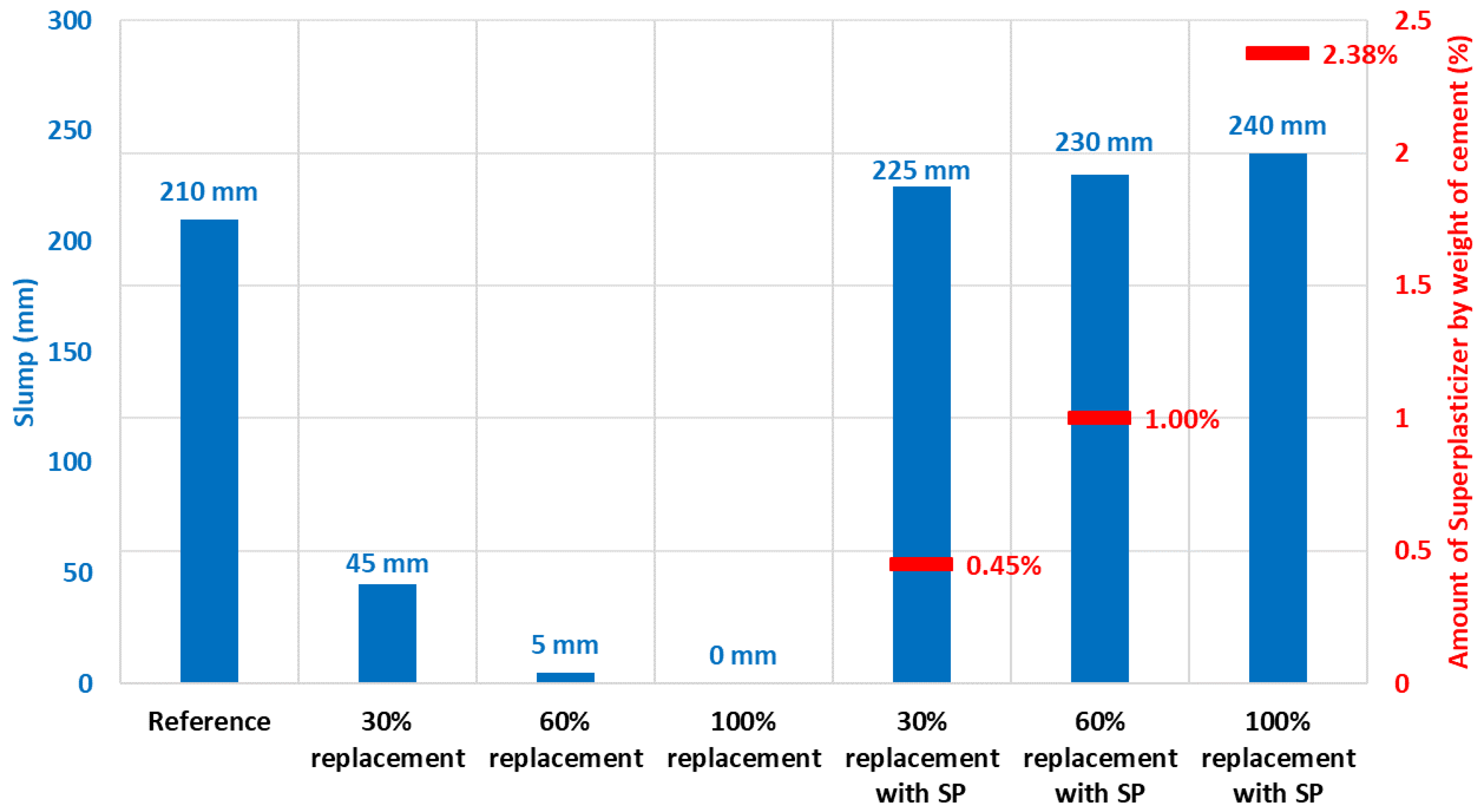
To evaluate the impacts of sand replacement with heat-treated soil on the fresh properties of the mortar mixes, a series of mixes were prepared with various percentages of sand replacement, and the slump values of the freshly mixed mortars were measured. Initially, mortar mixes without the use of superplasticiser were prepared, and the effect of replacement percentages was evaluated. As indicated in Figure 5, even a 30% sand replacement by the heat-treated soil altered the workability greatly and decreased the measured slump value by ~80%. For even higher percentages of sand replacement, slump values very close, or equal, to zero mm were measured. These results indicated the need of a rheology modifier and hence mixes with a generic superplasticiser (SP) were prepared.
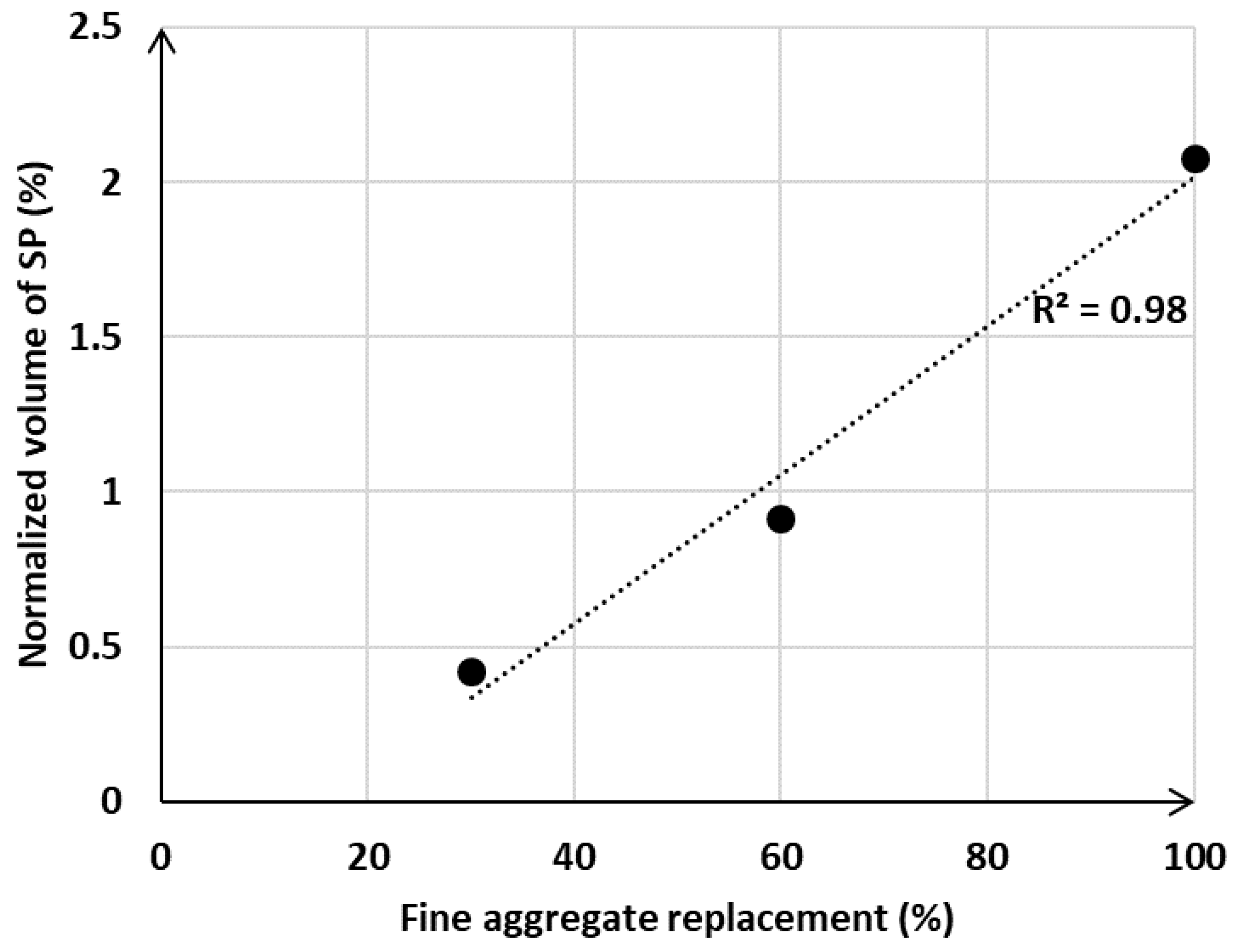
From the results obtained on mortar mixes with SP (left three columns in Figure 5), it is clear that the loss in slump value upon sand replacement can be easily eliminated by using a superplasticiser. The results indicate that the higher percentage of replacement utilised, the more superplasticiser is needed, but the required amounts did not exceed the manufacturer’s recommendations and usual dosage rates [61,62], and similar slump values to what was measured for the reference mortar were easily achieved. Moreover, a linear relationship was found between the amount of fine aggregates replaced (30%, 60% and 100%) and the corresponding volume of superplasticiser used in this study (Figure 6). The amounts of superplasticiser were normalised to correspond to a 210 mm slump (the slump value measured for the reference mortar).
3.2.3. Mechanical Performance
The compressive strengths of the mortars without superplasticiser are shown in Figure 7. For these mixes a 60% or 100% sand replacement resulted in a very low workability (5 mm and 0 mm slumps), and hence these mixes were considered non-practical without the use of a superplasticiser. Consequently, compression tests were conducted on lower fine aggregate replacements (15% and 30%). A 15% replacement (Figure 7) corresponds to a ~4% decrease in compressive strength, and a 30% replacement decreases the strength by no more than 9%.
For greater replacement rates, where the usage of a superplasticiser was necessary, the compressive strength decreased by ~8% for a 30% concrete sand replacement, by ~14% for a 60% replacement and by ~19% when the fine aggregate was completely replaced by the heat-treated soil. Based on the available literature [63,64,65,66], these results are considered extraordinary in terms of maintaining an adequate strength (>40 MPa) of the mortars even at very high replacement percentages.
Note that a 30% concrete sand replacement is considered a borderline case where the usage of a superplasticiser depends on the actual application. The fact that the losses in compressive strength were 8.4% and 8.5% for a 30% fine aggregate replacement with and without superplasticiser confirms that the superplasticiser had no effect on the measured mechanical performance at that level of FAR.
To further investigate the relationship between the extent of fine aggregate replacement and its impact on the mechanical performance, a correlation was made (Figure 8) between the replacement percentage and strength loss, and a linear relationship was found (making application-tailored planning easy). In conclusion, replacing the fine aggregate can be achieved both at lower and at greater amounts. The best FAR percentage depends on the requirements of the given application. The authors believe that in most applications a total replacement (100%) is a feasible option, with an appropriate rheology agent, and should be utilised for the sake of sustainability.
3.3. Heat-Treated Soil as Supplementary Cementitious Material
3.3.1. Impact of the Hydration State of the Soil on the Mechanical Performance
The effects of the prehydration and heat treatment of the soil were evaluated by comparing the 28-day compressive strength of pastes with 15% SCMs of various types (e.g., “as-received”, “oven dried”, “calcined” and “dry received”) (Figure 9). Results indicated that any contact of water would eliminate the cementitious properties of the heat-treated soil, which could not be recovered by drying at 110 °C. As-received and oven dried samples showed ~12% and ~13% strength losses, which highlighted that a 15% OPC replacement by these materials had essentially no cementitious properties and did not contribute to the measured compressive strength.
It is well known [33,67,68] that clays can only show pozzolanic activity, and therefore contribute to strength development, if they are heat-activated (i.e., calcined) at ~600–850 °C. Not-surprisingly, in-lab calcination at 750 °C activated the clay component of the soil, and hence the inclusion of the calcined soil resulted in a compressive strength slightly greater than the strength of the reference paste. The modest improvement can be attributed to the formation of additional calcium silicate hydrate (CSH) phases due to the pozzolanic reaction between portlandite and silicic acid [27,30,59,69,70,71].
Although the dry received sample had pozzolanic activity, samples prepared with it provided ~6% lower compressive strength compared with the paste with calcined soil. The lower measured compressive strength compared to the calcined soil likely originated from the lower temperature used for the heat treatment at the pyrolysis plant (~550–650 °C vs. Tcalcination = 750 °C), which was insufficient to achieve a high level of activation of the clays in the heat-treated soils [36,67,68]. The compositional differences, namely the lower kaolinite but greater metakaolin content of the calcined soil compared to that of the dry received soil, have been shown in the previous section and support the findings on the mechanical performance of the two different samples.
These results indicate that the pozzolanic properties of the calcined clay in the heat-treated soils can only be met if contact with water can be avoided; or, alternatively, if there is a possibility to reactivate the soils at or above ~750 °C. As this latter option would increase the carbon footprint of the materials substantially, alternative methods for cooling and dust control need to be considered.
3.3.2. Effects of SCM Percentage on the Mechanical Performance
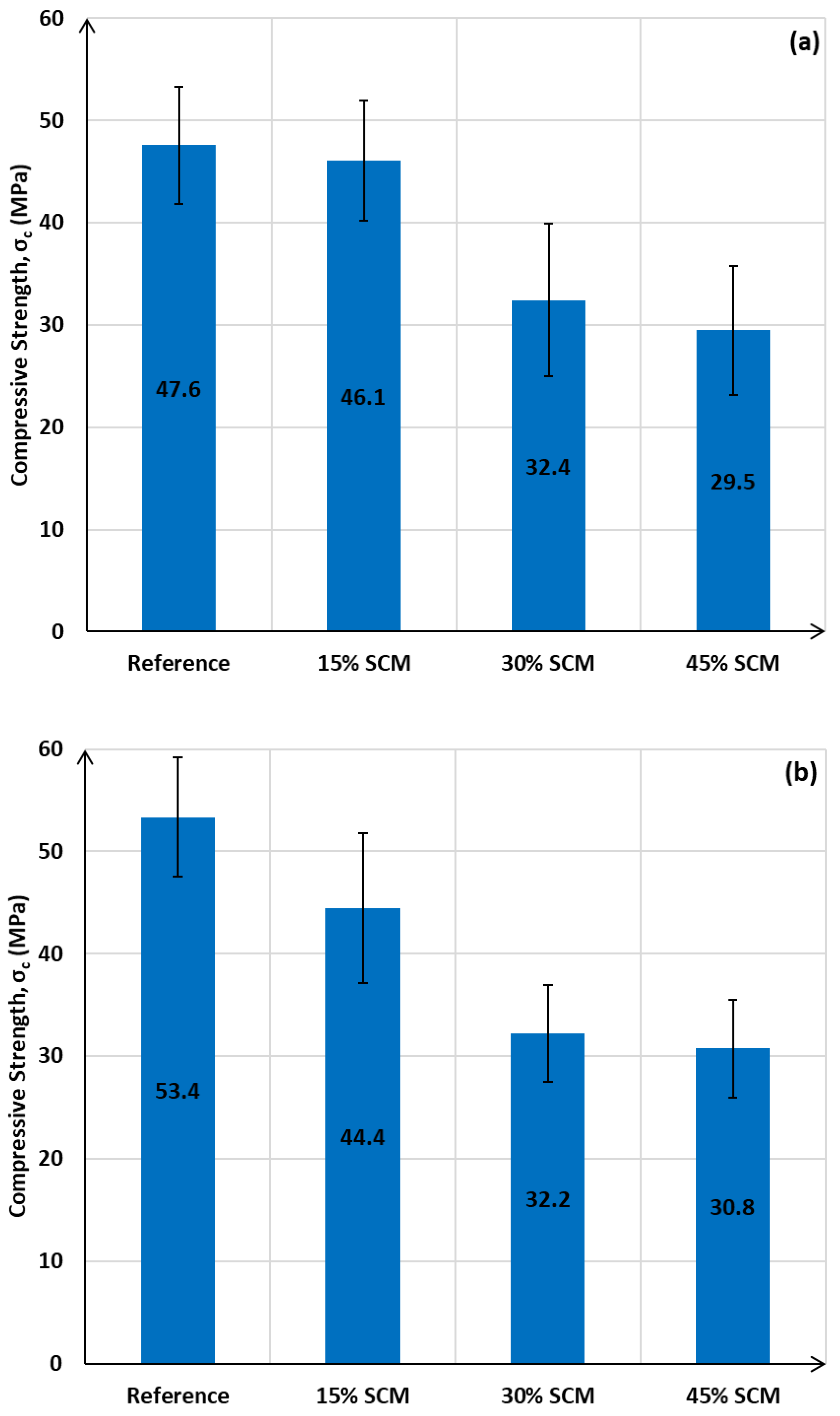
In another series of tests, paste mixes were prepared with various amounts of heat-treated dry received soil, and their impact on the measured compressive strength was evaluated. As indicated in Figure 10a, the compressive strength decreased with cement replacement, and although not in a linear trend, it appeared that either a smaller amount of OPC replacement (15%) with modest strength loss (47.6 MPa vs. 46.1 MPa) or a greater amount of replacement (45%) where the strength is already compromised would be beneficial. A 30% OPC replacement did not appear to be practical, since the strength loss of a 30% SCM paste is essentially comparable with the strength of the 45% SCM sample (32.4 MPa vs. 29.5 MPa). In the case of 45% replacement, the strength is still sufficient for moderate strength materials.
Mortar samples (using commercial fine aggregates only) with the same supplementary cementitious contents (15%, 30% and 45% heat-treated soil) (Figure 10b) showed a very similar trend to that observed for the paste mixes.
Interestingly, at higher SCM percentages (30% and 45%) the paste samples had comparable strengths to the mortar samples (usually, a transition from paste to mortar results in an improved mechanical performance). This phenomenon might be related to the composition of the heat-treated soil; based on the results presented earlier, the soil contained a large amount of quartz, and perhaps the total surface of the finely milled quartz in the paste samples with 30% and 45% heat-treated soil was sufficient to ensure the surface area for high levels of nucleation of hydration products. The extra amount of quartz (from the reference concrete sand) in the mortar samples with 30% and 45% of SCMs might be above the threshold where the increase in the total surface area has negligible additional nucleation effects.
3.3.3. Compositional Differences of the Hydrated Samples
The composition of 28-day-old paste samples was investigated with the FTIR technique (Figure 11). As anticipated, the greater the cement replacement percentage applied the more quartz signals (~695, ~777, ~796, ~1057 and ~1163 cm−1) were observed in the FTIR spectrum (as outlined above, the heat-treated soil contained a large amount of quartz). Secondly, an increasing amount of surface bound water (~2350–3650, ~1640 cm−1) [72] was observed with increasing SCM quantities, a trend which is likely related to the clay content (e.g., kaolinite, metakaolin, illite, calcined illite) of the heat-treated soil. In our previous study [29] we showed that calcined clay shows a more pronounced water uptake compared with that of the OPC. More importantly, it was possible to follow the pozzolanic reaction in the samples of various SCM contents by monitoring their residual portlandite contents. In the pozzolanic reaction the portlandite reacts with silicic acid coming from the clay and form calcium silicate hydrates. The loss in portlandite content is hence an indicator of the extent of pozzolanic reaction [30].
In reality, the heat-treated soil SCM contained a large amount of non-cementitious and non-pozzolanic materials (i.e., quartz), and thus the compressive strengths of the samples decreased with increasing SCM contents (Figure 10 in the previous paragraph). However, the heat-treated soil contains, in general, sufficient amounts of pozzolanic material to partially mitigate the loss of strength through the formation of additional CSH from the pozzolanic reaction. For example, replacing 15% of the OPC with the heat-treated soil resulted in a very modest strength loss (~3%), and the inset in Figure 11 shows that the 15% SCM sample did have less portlandite compared to the reference. Surprisingly, the 30% SCM paste showed almost identical portlandite content to what was measured for the 15% SCM, and hence a greater strength loss (~30%) was observed by doubling the SCM’s amount (i.e., moving from 15% to 30%). This is because the 30% SCM sample had very similar pozzolanic activity to that of the 15% SCM paste, but the 30% soil also contributed a large amount of non-cementitious material in the mix. In the 45% SCM paste almost all of the portlandite was consumed (indicating high pozzolanic activity), and the minor strength loss (32.4 MPa → 29.5 MPa) compared with the strength of the 30% SCM is hence justified. The moderate pozzolanic activity of the 30% SCM paste is unexpected and will require further investigation.
4. Summary and Conclusions
In this study we investigated the possibility of using remediated PFAS-contaminated soils, post pyrolysis treatment, in cement paste and mortar applications. The analytical investigations of the heat-treated soils clearly showed a huge potential for them to be used either as a supplementary cementitious material or as fine aggregate replacement, largely due to their compositional properties (i.e., the presence of large amounts of quartz and calcined clay).
The usefulness of the heat-treated soil as fine aggregate replacement stemmed from the fact that the measured water absorption, specific gravity and particle size distribution were all adequately similar to those of the reference fine aggregate. Not surprisingly, considerable mechanical performances were observed for mortars containing heat-treated soil (45.4–53.9 MPa); less than 20% strength loss, compared to the reference sample, was measured for 100% fine aggregate replacement. Thus, the heat-treated soil can serve as a substitute material for standard concrete sand. While a high percentage of fine aggregate replacement with the treated soil is certainly achievable for many applications, some caution is required, as it can have a negative effect on the fresh properties of the mortars. For example, a 30% FAR changed the slump value from 210 mm to 45 mm. In this study a generic superplasticiser proved successful in overcoming the reduced workability by applying the normal dosage rate recommended by the supplier (i.e., no more than 2.5 wt% for 100% FAR).
When using the heat-treated soil as a supplementary cementitious material, one should bear in mind that any contact with water prior to mixing with cement diminishes the cementitious properties of the heat-treated soil and thus must be avoided. Another important parameter for gaining cementitious behaviour from the heat-treated soil is applying an adequate temperature in the heating process. For instance, it was shown that a 750 °C heating resulted in a greater metakaolin content, which enhanced pozzolanic properties, compared with that of a typical industrial treatment of 550–650 °C. A strong correlation was found between the amount of consumed portlandite (i.e., pozzolanic activity) and the mechanical performance of hardened 28-day-old pastes and mortars, confirming that the heat-treated soil did contain sufficient pozzolanic phases. Based on the results from this study, when only modest compressive strength loss is acceptable (~3% in cement pastes), no more than 15% heat-treated soil should be used as cement replacement. In applications where sustainability is the key driving force and a moderate strength (not less than 30 MPa) is satisfactory, a 45% replacement can be utilised.
In summary, the pyrolysis process developed for heat-treating and remediating PFAS-contaminated soils is favourable not just in addressing an emerging and widespread environmental contaminant, but also to value add to a material otherwise considered industrial waste. We demonstrated that the pyrolysed soil can be used for both SCM and FAR in cement pastes and mortars, and thus lead to the avoidance of the disposal of large quantities of materials in landfills.
In future studies, the impacts of the heat-treated soils in concrete mixes can be examined, and perhaps the combined SCM+FAR properties of the soils can be investigated by using the treated soils without any particle size separation (i.e., without sieving). The durability aspects of the concrete incorporating heat-treated soils require some attention as well. While not a focus of this study, further work should also address the pre-mixing of contaminated wastes to ensure a consistent mineralogy of the heat-treated soils for applications in pastes and mortars.
The authors consider that case studies like this should become “business as usual” for many remedial bids, particularly in areas where there are shortages of aggregates or where large construction projects unearth PFAS-contaminated soils.
Author Contributions
Conceptualization, A.F. and W.P.G.; methodology, A.F.; formal analysis, A.F.; investigation, A.F. and C.G.; writing—original draft preparation, A.F.; writing—review and editing, A.F., W.P.G. and F.C.; visualization, A.F.; supervision, W.P.G. and F.C.; project administration, W.P.G.; funding acquisition, W.P.G. and F.C. All authors have read and agreed to the published version of the manuscript.
Funding
This research was funded in part by the Australian Research Council’s Special Research Initiatives scheme for PFAS remediation of soils, waters and debris, grant number SR180100009. Cash and in-kind contributions from industry partners Renex Op Co Pty Ltd. and The Remediation Group Pty Ltd. are gratefully acknowledged.
Acknowledgments
The authors would like to thank Gyongyver Engloner for preparing the graphical abstract of this study.
Conflicts of Interest
The authors declare no conflict of interest.
References
- Gagg, C.R. Cement and concrete as an engineering material: An historic appraisal and case study analysis. Eng. Fail. Anal. 2014, 40, 114–140. [Google Scholar] [CrossRef]
- CO2—What about It. Available online: https://www.slideshare.net/lesecq/co2-what-about-it (accessed on 17 March 2020).
- Davidson, E. Defining the trend: Cement Consumption versus Gross Domestic Product. Glob. Cem. Mag. 2014, 8–14. [Google Scholar]
- Andrew, R.M. Global CO2 emissions from cement production, 1928–2018. Earth Syst. Sci. Data 2019, 11, 1675–1710. [Google Scholar] [CrossRef] [Green Version]
- Lord, M. Zero Carbon Industry Plan: Rethinking Cement; Zero Carbon Australia; Beyond Zero Emissions Inc.: Melbourne, Australia, 2017. [Google Scholar]
- Scrivener, K. Options for the future of cement. Indian Concr. J. 2014, 88, 11–21. [Google Scholar]
- Naqi, A.; Jang, J.G. Recent Progress in Green Cement Technology Utilizing Low-Carbon Emission Fuels and Raw Materials: A Review. Sustainability 2019, 11, 537. [Google Scholar] [CrossRef] [Green Version]
- Courland, R. Concrete planet. The Strange and Fascinating Story of the World’s Most Common Man-Made Material; Promethius Books: Buffalo, NY, USA, 2011. [Google Scholar]
- AustralianGovernment. Per- and Poly-Fluoroalkyl Substances (PFASs). Available online: http://www.environment.gov.au/protection/chemicals-management/pfas#a4 (accessed on 31 March 2020).
- Lechner, M.; Knapp, H. Carryover of Perfluorooctanoic Acid (PFOA) and Perfluorooctane Sulfonate (PFOS) from Soil to Plant and Distribution to the Different Plant Compartments Studied in Cultures of Carrots (Daucus carota ssp. Sativus), Potatoes (Solanum tuberosum), and Cucumbers (Cucumis Sativus). J. Agric. Food Chem. 2011, 59, 11011–11018. [Google Scholar] [CrossRef]
- Kowalczyk, J.; Ehlers, S.; Fürst, P.; Schafft, H.; Lahrssen-Wiederholt, M. Transfer of Perfluorooctanoic Acid (PFOA) and Perfluorooctane Sulfonate (PFOS) From Contaminated Feed Into Milk and Meat of Sheep: Pilot Study. Arch. Environ. Contam. Toxicol. 2012, 63, 288–298. [Google Scholar] [CrossRef]
- Squadrone, S.; Ciccotelli, V.; Prearo, M.; Favaro, L.; Scanzio, T.; Foglini, C.; Abete, M.C. Perfluorooctane sulfonate (PFOS) and perfluorooctanoic acid (PFOA): Emerging contaminants of increasing concern in fish from Lake Varese, Italy. Environ. Monit. Assess. 2015, 187, 438. [Google Scholar] [CrossRef]
- Nakayama, S.; Harada, K.; Inoue, K.; Sasaki, K.; Seery, B.; Saito, N.; Koizumi, A. Distributions of perfluorooctanoic acid (PFOA) and perfluorooctane sulfonate (PFOS) in Japan and their toxicities. Environ. Sci. Int. J. Environ. Physiol. Toxicol. 2005, 12, 293–313. [Google Scholar]
- Steenland, K.; Tinker, S.; Shankar, A.; Ducatman, A. Association of perfluorooctanoic acid (PFOA) and perfluorooctane sulfonate (PFOS) with uric acid among adults with elevated community exposure to PFOA. Environ. Health Persp. 2010, 118, 229–233. [Google Scholar] [CrossRef] [Green Version]
- Bost, P.C.; Strynar, M.J.; Reiner, J.L.; Zweigenbaum, J.A.; Secoura, P.L.; Lindstrom, A.B.; Dye, J.A. U.S. domestic cats as sentinels for perfluoroalkyl substances: Possible linkages with housing, obesity, and disease. Environ. Res. 2016, 151, 145–153. [Google Scholar] [CrossRef] [PubMed]
- Liu, Z.; Lu, Y.; Wang, P.; Wang, T.; Liu, S.; Johnson, A.C.; Sweetman, A.J.; Baninla, Y. Pollution pathways and release estimation of perfluorooctane sulfonate (PFOS) and perfluorooctanoic acid (PFOA) in central and eastern China. Sci. Total Environ. 2017, 580, 1247–1256. [Google Scholar] [CrossRef] [PubMed] [Green Version]
- Simon, J.A.; Abrams, S.; Bradburne, T.; Bryant, D.; Burns, M.; Cassidy, D.; Cherry, J.; Chiang, S.-Y.; Cox, D.; Crimi, M.; et al. PFAS Experts Symposium: Statements on regulatory policy, chemistry and analytics, toxicology, transport/fate, and remediation for per- and polyfluoroalkyl substances (PFAS) contamination issues. Remediat. J. 2019, 29, 31–48. [Google Scholar] [CrossRef]
- FEATURE: Sands of Time—Clock Ticking for Construction During Aggregates Shortage. Available online: https://www.imeche.org/news/news-article/feature-sands-of-time-clock-ticking-for-construction-during-aggregates-shortage (accessed on 17 March 2020).
- Industry Professionals Refute Authors’ Sand Shortage Claim? Available online: https://www.quarrymagazine.com/2019/10/11/industry-professionals-refute-authors-sand-shortage-claim/ (accessed on 17 March 2020).
- Footprints in the Sand. Available online: https://www.worldcement.com/special-reports/16062015/footprints-in-the-sand-829/ (accessed on 17 March 2020).
- Why the World Is Running Out of Sand. Available online: https://www.bbc.com/future/article/20191108-why-the-world-is-running-out-of-sand (accessed on 17 March 2020).
- We’re Running Out of Sand and Cities Are to Blame. Available online: https://www.forbes.com/sites/lauriewinkless/2019/08/22/were-running-out-of-sand-and-cities-are-to-blame/#4e5f10e21240 (accessed on 17 March 2020).
- PFAS Soil Stockpiles Sitting in Melbourne’s Inner-West. Available online: https://www.theage.com.au/national/victoria/pfas-soil-stockpiles-sitting-in-melbourne-s-inner-west-20200309-p5488p.html (accessed on 17 March 2020).
- Jain, P.; Kim, H.; Townsend, T.G. Heavy metal content in soil reclaimed from a municipal solid waste landfill. Waste Manag. 2005, 25, 25–35. [Google Scholar] [CrossRef] [PubMed]
- Tiller, K. Urban soil contamination in Australia. Soil Res. 1992, 30, 937–957. [Google Scholar] [CrossRef]
- Chen, Q.Y.; Tyrer, M.; Hills, C.D.; Yang, X.M.; Carey, P. Immobilisation of heavy metal in cement-based solidification/stabilisation: A review. Waste Manag. 2009, 29, 390–403. [Google Scholar] [CrossRef] [PubMed]
- Fernandez, R.; Martirena, F.; Scrivener, K.L. The origin of the pozzolanic activity of calcined clay minerals: A comparison between kaolinite, illite and montmorillonite. Cem. Concr. Res. 2011, 41, 113–122. [Google Scholar] [CrossRef]
- Scrivener, K.; Martirena, F.; Bishnoi, S.; Maity, S. Calcined clay limestone cements (LC3). Cem. Concr. Res. 2018, 114, 49–56. [Google Scholar] [CrossRef]
- Fehervari, A.; Gallage, C.; MacLeod, A.; Garcez, E.; Zhang, J.; Antic, A.; Gates, W.; Collins, F. Workability and Fresh Properties of a Low CO2 Footprint Concrete. In Proceedings of the Concrete 2019 Concrete in Practice—Progress through Knowledge Biennial National Conference of the Concrete Institute of Australia, Sydney, Australia, 8–11 September 2019. [Google Scholar]
- Antoni, M.; Rossen, J.; Martirena, F.; Scrivener, K. Cement substitution by a combination of metakaolin and limestone. Cem. Concr. Res. 2012, 42, 1579–1589. [Google Scholar] [CrossRef]
- Avet, F.; Snellings, R.; Alujas Diaz, A.; Ben Haha, M.; Scrivener, K. Development of a new rapid, relevant and reliable (R3) test method to evaluate the pozzolanic reactivity of calcined kaolinitic clays. Cem. Concr. Res. 2016, 85, 1–11. [Google Scholar] [CrossRef]
- Sabir, B.B.; Wild, S.; Bai, J. Metakaolin and calcined clays as pozzolans for concrete: A review. Cem. Concr. Compos. 2001, 23, 441–454. [Google Scholar] [CrossRef]
- Tironi, A.; Trezza, M.; Scian, A.N.; Irassar, E. Assessment of Pozzolanic Activity of Different Calcined Clays. Cem. Concr. Compos. 2013, 37, 319–327. [Google Scholar] [CrossRef]
- Scrivener, K. Cement Chemistry and Sustainable Cementitious Materials. Online Course, edX. 2019. Available online: https://www.edx.org/course/cement-chemistry-and-sustainable-cementitious-mate?source=aw&awc=6798_1590375041_5d6891d65617f1b609b1c5aca4bdb7c5&utm_source=aw&utm_medium=affiliate_partner&utm_content=text-link&utm_term=422873_My+Mooc (accessed on 18 March 2019).
- Geng, H.; Chen, W.; Li, Q.; Shui, Z.; Yuan, B. Effect of Pre-dispersing Metakaolin in Water on the Properties, Hydration, and Metakaolin Distribution in Mortar. Front. Mater. 2019, 6. [Google Scholar] [CrossRef]
- Scrivener, K.; Avet, F.; Maraghechi, H.; Zunino, F.; Ston, J.; Hanpongpun, W.; Favier, A. Impacting factors and properties of limestone calcined clay cements (LC3). Green Mater. 2019, 7, 3–14. [Google Scholar] [CrossRef] [Green Version]
- Martirena, F.; Díaz, E.; Rocha, D.; Maraghechi, H.; Scrivener, K.L. Performance of Concrete Made with a Calcined Clay—Limestone-Portland Cement Exposed to Natural Conditions. In Proceedings of the Sixth International Conference on Durability of Concrete Structures, Leeds, UK, 18–20 July 2018; pp. 244–247. [Google Scholar]
- Paiva, H.; Velosa, A.; Cachim, P.; Ferreira, V. Effect of pozzolans with different physical and chemical characteristics on concrete properties. Mater. Constr. 2016, 66. [Google Scholar] [CrossRef]
- Dhandapani, Y.; Sakthivel, T.; Santhanam, M.; Gettu, R.; Pillai, R.G. Mechanical properties and durability performance of concretes with Limestone Calcined Clay Cement (LC3). Cem. Concr. Res. 2018, 107, 136–151. [Google Scholar] [CrossRef]
- Standards Australia, AS. 3972. General Purpose and Blended; Cements; Standards Australia: Sydney, Australia, 2010. [Google Scholar]
- ASTM. C305 Standard Practice for Mechanical Mixing of Hydraulic Cement Pastes and Mortars of Plastic Consistency; ASTM International: West Conshohocken, PA, USA, 2014. [Google Scholar]
- ASTM. C109/C109M Standard Test Method for Compressive Strength of Hydraulic Cement Mortars (Using 75 mm Cube Specimens); ASTM International: West Conshohocken, PA, USA, 2016. [Google Scholar]
- Standards Australia, AS. 1012.3.1. Methods of Testing Concrete. Method 3: Determination of Properties Related to the consistency of concrete—Slump test; Standards Australia: Sydney, Australia, 2014. [Google Scholar]
- Standards Australia, AS. 1012.8.1. Methods of Testing Concrete. Method for Making and Curing Concrete—Compression and Indirect Tensile Test Specimens; Standards Australia: Sydney, Australia, 2014. [Google Scholar]
- Renex Technology. Available online: http://www.renexgroup.com/ (accessed on 9 April 2020).
- ASTM. D6913/D6913M—17 Standard Test Methods for Particle-Size Distribution (Gradation) of Soils Using Sieve Analysis; ASTM International: West Conshohocken, PA, USA, 2017. [Google Scholar]
- Standards Australia, AS. 1141.5. Methods for Sampling and Testing Aggregates, Method 5: Particle Density and Water Absorption of Fine Aggregate; Standards Australia: Sydney, Australia, 2000. [Google Scholar]
- Msinjili, N.S.; Gluth, G.J.G.; Sturm, P.; Vogler, N.; Kühne, H.-C. Comparison of calcined illitic clays (brick clays) and low-grade kaolinitic clays as supplementary cementitious materials. Mater. Struct. 2019, 52, 94. [Google Scholar] [CrossRef] [Green Version]
- Cullity, B.D.; Stock, S.R. Elements of X-Ray Diffraction, 3rd ed.; Pearson: London, UK, 2001. [Google Scholar]
- Żbik, M.S.; Raftery, N.A.; Smart, R.S.C.; Frost, R.L. Kaolinite platelet orientation for XRD and AFM applications. Appl. Clay Sci. 2010, 50, 299–304. [Google Scholar] [CrossRef] [Green Version]
- Kłosek-Wawrzyn, E.; Małolepszy, J.; Murzyn, P. Sintering Behavior of Kaolin with Calcite. Procedia Eng. 2013, 57, 572–582. [Google Scholar] [CrossRef] [Green Version]
- Mohsen, Q.; El-maghraby, A. Characterization and assessment of Saudi clays raw material at different area. Arab. J. Chem. 2010, 3, 271–277. [Google Scholar] [CrossRef] [Green Version]
- Alouani, M.E.; Alehyen, S.; Achouri, M.E.; Taibi, M. Preparation, Characterization, and Application of Metakaolin-Based Geopolymer for Removal of Methylene Blue from Aqueous Solution. J. Chem. 2019. [Google Scholar] [CrossRef]
- Kenne Diffo, B.B.; Elimbi, A.; Cyr, M.; Dika Manga, J.; Tchakoute Kouamo, H. Effect of the rate of calcination of kaolin on the properties of metakaolin-based geopolymers. J. Asian Ceram. Soc. 2015, 3, 130–138. [Google Scholar] [CrossRef] [Green Version]
- Śrondoń, J. X-Ray Powder Diffraction Identification of Illitic Materials. Clays Clay Miner. 1984, 32, 337–349. [Google Scholar] [CrossRef]
- Pentrak, M.; Madejova, J.; Andrejkovičová, S.; Uhlik, P.; Komadel, P. Stability of kaolin sand from the Vyšný Petrovec deposit (south Slovakia) in an acid environment. Geol. Carpathica 2012, 63. [Google Scholar] [CrossRef]
- Li, Y.-S.; Church, J.S.; Woodhead, A.L. Infrared and Raman spectroscopic studies on iron oxide magnetic nano-particles and their surface modifications. J. Magn. Magn. Mater. 2012, 324, 1543–1550. [Google Scholar] [CrossRef]
- Namduri, H.; Nasrazadani, S. Quantitative analysis of iron oxides using Fourier transform infrared spectrophotometry. Corros. Sci. 2008, 50, 2493–2497. [Google Scholar] [CrossRef]
- Sperinck, S.; Raiteri, P.; Marks, N.; Wright, K. Dehydroxylation of kaolinite to metakaolin—A molecular dynamics study. J. Mater. Chem. 2011, 21, 2118–2125. [Google Scholar] [CrossRef] [Green Version]
- Brindley, G.W.; Nakahira, M. The Kaolinite-Mullite Reaction Series: II, Metakaolin. J. Am. Ceram. Soc. 1959, 42, 314–318. [Google Scholar] [CrossRef]
- Malhotra, V.M. Results of a Laboratory Study—Superplasticizers in Concrete; Canada Center For Mineral and Energy Technology Department of Energy, Mines and Resources: Ottawa, ON, Canada, 1978.
- Muhit, I.B. Dosage Limit Determination of Superplasticizing Admixture and Effect Evaluation on Properties of Concrete. Int. J. Sci. Eng. Res. 2013, 4, 1–5. [Google Scholar]
- Mageswari, M.; Vidivelli, B. The Use of Sawdust Ash as Fine Aggregate Replacement in Concrete. Mater. Sci. 2009, 720–726. [Google Scholar]
- Rahman, S.; Farnaz, T.; Islam, T. Experimental Investigation of Concrete by Partial Replacement of Sand with Red Soil. In Proceedings of the 5th International Conference on Engineering Research, Innovation and Education (ICERIE 2019), Shahjalal University of Science and Technology (SUST), Sylhet, Bangladesh, 25–27 January 2019. [Google Scholar]
- Kalhara, N.; Perera, A.; Perera, A.; Lankathilake, N.; Ranasingh, T. Suitability of Soil Washed Sand as Fine Aggregates to Replace River Sand in the Concrete. Am. Sci. Res. J. Eng. Technol. Sci. 2018, 46, 25–33. [Google Scholar]
- Prakash, K.S.; Rao, C.H. Study on Compressive Strength of Quarry Dust as Fine Aggregate in Concrete. Adv. Civ. Eng. 2016. [Google Scholar] [CrossRef] [Green Version]
- Elimbi, A.; Tchakoute, H.K.; Njopwouo, D. Effects of calcination temperature of kaolinite clays on the properties of geopolymer cements. Constr. Build. Mater. 2011, 25, 2805–2812. [Google Scholar] [CrossRef]
- Garg, N.; Skibsted, J. Dissolution kinetics of calcined kaolinite and montmorillonite in alkaline conditions: Evidence for reactive Al (V) sites. J. Am. Ceram. Soc. 2019, 102, 7720–7734. [Google Scholar] [CrossRef]
- Sargent, P. The development of alkali-activated mixtures for soil stabilisation. In Handbook of Alkali-Activated Cements, Mortars and Concretes; Woodhead Publishing: Cambridge, UK, 2015; pp. 555–604. [Google Scholar] [CrossRef]
- Dodson, V.H. Pozzolans and the Pozzolanic Reaction. In Concrete Admixtures; Springer: Boston, MA, USA, 1990. [Google Scholar] [CrossRef]
- Dunstan, E.R. How Does Pozzolanic Reaction Make Concrete ‘Green”? In Proceedings of the World of Coal Ash (WOCA) Conference, Denver, CO, USA, 9–12 May 2011. [Google Scholar]
- Madejová, J.; Komadel, P. Baseline Studies of the Clay Minerals Society Source Clays: Infrared Methods. Clays Clay Miner. 2001, 49, 410–432. [Google Scholar] [CrossRef]
Figure 1.
XRD patterns of concrete sand and calcined soil (<75 µm fraction). Abbreviations: Q-quartz, MK-metakaolin, F-feldspar, I-illite, C-calcium carbonate, Mi-mica.
Figure 1.
XRD patterns of concrete sand and calcined soil (<75 µm fraction). Abbreviations: Q-quartz, MK-metakaolin, F-feldspar, I-illite, C-calcium carbonate, Mi-mica.

Figure 2.
XRD patterns of dry received and calcined soil (<75 µm fraction). Abbreviations: Q-quartz, MK-metakaolin, F-feldspar, I-illite, C-calcium carbonate, Mi-mica. Note that the baseline of the dry received soil is shifted by 1000 cps upward for clarity and that the original baseline of the dry received soil overlaps with that of the calcined soil.

Figure 3.
FTIR spectrum of the reference concrete sand, the calcined soil and the dry received soil. Note there were no absorbance peaks identified within the 1300–4000 cm−1 range.
Figure 3.
FTIR spectrum of the reference concrete sand, the calcined soil and the dry received soil. Note there were no absorbance peaks identified within the 1300–4000 cm−1 range.

Figure 4.
Particle size distribution curves of the concrete sand and heat-treated soil.

Figure 5.
The measured slump values of freshly mixed mortars and the amount of superplasticiser used in the mixes (right three columns).
Figure 5.
The measured slump values of freshly mixed mortars and the amount of superplasticiser used in the mixes (right three columns).

Figure 6.
Relationship between fine aggregate replacement and amount of superplasticiser used.

Figure 7.
Compressive strength of mortar samples without (a) and with (b) the use of superplasticiser.
Figure 7.
Compressive strength of mortar samples without (a) and with (b) the use of superplasticiser.

Figure 8.
Linear relationship between fine aggregate replacement percentage and loss in strength.

Figure 9.
Compressive strengths of paste samples hydrated for 28 days with various types of heat-treated soils.
Figure 9.
Compressive strengths of paste samples hydrated for 28 days with various types of heat-treated soils.

Figure 10.
Compressive strength of paste (a) and mortar (b) samples incorporating various amounts of heat-treated soils as SCMs.
Figure 10.
Compressive strength of paste (a) and mortar (b) samples incorporating various amounts of heat-treated soils as SCMs.

Figure 11.
FTIR spectrum of 28-day-old paste samples incorporating various amounts of heat-treated soils as SCMs.
Figure 11.
FTIR spectrum of 28-day-old paste samples incorporating various amounts of heat-treated soils as SCMs.


Table 1.
Composition of ordinary Portland cement.
| Clinker Constituents (%) | SiO2 | Al2O3 | Fe2O3 | MgO | CaO | Na2O | TiO2 | K2O | MnO | P2O3 | SO3 |
| 19.9 | 4.7 | 3.38 | 1.3 | 63.9 | 0.17 | 0.25 | 0.45 | 0.08 | 0.06 | 2.5 | |
| Gypsum (%) | 3.3 | ||||||||||
| Loss on ignition | 3 | ||||||||||
| Bulk density (kg/m3) | ~1400 | ||||||||||
| Specific gravity | ~3.0 | ||||||||||
| pH | ~12 | ||||||||||
| Particle size | ~90% less than 35 μm and ~30% less than 7 μm | ||||||||||
Table 2.
Details of the mixes investigated in this study.
| Mix Designation | Binder (wt%) | w:b Ratio | SP (wt% of Binder) | Aggregate (wt%) | Aggregate:Binder | |||
|---|---|---|---|---|---|---|---|---|
| OPC | SCM | Concrete Sand | FAR | |||||
| Mortars | Reference | 100 | 0 | 0.45 | 0 | 100 | 0 | 1:2 |
| 15% FAR | 100 | 0 | 0.45 | 0 | 85 | 15 | 1:2 | |
| 30% FAR | 100 | 0 | 0.45 | 0 | 70 | 30 | 1:2 | |
| 60% FAR | 100 | 0 | 0.45 | 0 | 40 | 60 | 1:2 | |
| 100% FAR | 100 | 0 | 0.45 | 0 | 0 | 100 | 1:2 | |
| 30% FAR with SP | 100 | 0 | 0.45 | 0.45 | 70 | 30 | 1:2 | |
| 60% FAR with SP | 100 | 0 | 0.45 | 1.00 | 40 | 60 | 1:2 | |
| 100% FAR with SP | 100 | 0 | 0.45 | 2.38 | 0 | 100 | 1:2 | |
| 15% SCM | 85 | 15 | 0.45 | 0 | 100 | 0 | 1:2 | |
| 30% SCM | 70 | 30 | 0.45 | 0 | 100 | 0 | 1:2 | |
| 45% SCM | 55 | 45 | 0.45 | 0 | 100 | 0 | 1:2 | |
| Pastes | Reference | 100 | 0 | 0.45 | 0 | 0 | 0 | - |
| 15% SCM | 85 | 15 | 0.45 | 0 | 0 | 0 | - | |
| 30% SCM | 70 | 30 | 0.45 | 0 | 0 | 0 | - | |
| 45% SCM | 55 | 45 | 0.45 | 0 | 0 | 0 | - | |
© 2020 by the authors. Licensee MDPI, Basel, Switzerland. This article is an open access article distributed under the terms and conditions of the Creative Commons Attribution (CC BY) license (http://creativecommons.org/licenses/by/4.0/).
Share and Cite
MDPI and ACS Style
Fehervari, A.; Gates, W.P.; Gallage, C.; Collins, F. Suitability of Remediated PFAS-Affected Soil in Cement Pastes and Mortars. Sustainability 2020, 12, 4300. https://doi.org/10.3390/su12104300
AMA Style
Fehervari A, Gates WP, Gallage C, Collins F. Suitability of Remediated PFAS-Affected Soil in Cement Pastes and Mortars. Sustainability. 2020; 12(10):4300. https://doi.org/10.3390/su12104300
Chicago/Turabian StyleFehervari, Andras, Will P. Gates, Chathuranga Gallage, and Frank Collins. 2020. "Suitability of Remediated PFAS-Affected Soil in Cement Pastes and Mortars" Sustainability 12, no. 10: 4300. https://doi.org/10.3390/su12104300
Note that from the first issue of 2016, this journal uses article numbers instead of page numbers. See further details here.