Failure Mechanisms of Rheological Coal Roadway


1
Key Laboratory of Deep Coal Resource Mining; School of Mines; China University of Mining and Technology, Xuzhou 221116, China
2
Department of Civil, Environmental and Mining Engineering, the University of Western Australia, Perth 6009, Australia
*
Author to whom correspondence should be addressed.
Sustainability 2020, 12(7), 2885; https://doi.org/10.3390/su12072885
Submission received: 17 February 2020
/
Revised: 1 April 2020
/
Accepted: 2 April 2020
/
Published: 4 April 2020
Abstract
:The roadway instability in deep underground conditions has attracted constant concerns in recent years, as it seriously affects the efficiency of coal mining and the safety of personnel. The large rheological deformations normally occur in deep roadway with soft coal mass. However, the failure mechanism of such roadways is still not clear. In this study, based on a typical soft coal roadway in the field, the in-situ measurements and rock mass properties were obtained. The rheological deformation of that roadway was revealed. Then a time-dependent 3D numerical model was established and verified. Based on the verified model, the deformation properties and evolutionary failure mechanism of deep coal roadway were investigated in detail. The results showed that the deformation of the soft coal roadway demonstrated rheological behavior and the applied support structures failed completely. After roadway excavation, the maximum and minimum stresses around the roadway deteriorated gradually with the increase of time. The failure zones in soft coal mass expanded increasingly over time, which had a negative effect on roadway stability in the long-term. According to the findings, helpful suggestions were further presented to control the rheological deformation in the roadway. This research systematically reveals the instability mechanism of the deep coal roadway and provides some strategies for maintaining roadway stability, which can significantly promote the sustainability of mining in deep underground coal mines.
1. Introduction
Roadway instability is a challenging issue in deep underground coal mines, which seriously jeopardizes personnel safety [1]. In China, most coal resources are buried deeper than 700 m especially in the east of China. Due to the rapidly growing demands of coal production, the mining depth increases quickly at a speed of 10–25 m per year [2]. Compared with a roadway at a shallow depth, the failure mechanism of rock mass surrounding deep roadway is significantly different. Specifically, the time-dependent feature of rock mass (i.e. rheology property) in deep conditions is more severe [3,4]. After roadway excavation, the deformation of the roadway with weak rock mass and soft coal mass rapidly increases with time, which causes the evolutionary failure of the roadway. Normally, coal roadway instability occurs over several months, and worse, the maintenance cost exceeds the tunneling cost considerably [5].
To investigate the failure of soft rock mass roadway in deep mines, some methods such as theoretic analysis [6], field tests [7,8,9], physical simulation models [10,11], and numerical modeling were presented and utilized. Nowadays, different numerical simulation methods were developed and adopted due to their special advantages including low costs, high efficiency, and repeatability [12,13]. It has been proved that the instability of a roadway could be thoroughly investigated especially in stress states, damage zones, and deformation evolution by numerical modeling approaches [14,15]. For example, based on the software of UDEC (v 5.0) or 3DEC (v 5.0) [16,17,18,19], the failure mechanism of a roadway considering various conditions such as high horizontal in-situ stress, deep buried depth, squeezing phenomenon, and mining-induced stresses were studied. By FLAC (v 7.0) or FLAC3D (v 5.0) methods [20,21,22,23], the stability of a roadway related to excavation size, geological conditions, stress states, rheological properties of rock mass, and the development of plastic zone was investigated. In addition, other numerical simulation methods such as RFPA (v 1.0) [24], ABAQUS (v 6.0) [25], RS2 (V 10.0) [26], and hybrid numerical approaches such as “FLAC3D+FLAC” [27] and “FLAC3D+RS2” [28,29] were adopted for analyzing roadway deformation and failure behaviors.
The mentioned studies by numerical simulations have proved that the numerical methods are practicable and efficient in investigating roadway instability. However, it should be pointed out that there are still some limitations of cognition of engineering because of complex geological conditions deep underground. The failure mechanism of soft coal roadway needs to be further revealed. To the authors’ knowledge, the related researches on roadway stability still have some limitations as follows: (1) The time-dependent behavior of the roadway has been confirmed by many engineering practices. Therefore, the numerical simulation should reflect the time effect on roadway stability instead of just focusing on the final status of the roadway through traditional numerical simulation. (2) Based on some experimental results, it has been proved that soft coal exhibited more obvious rheological features than high strength rock. Thus, in terms of a deep soft coal roadway, it is necessary to analyze the evolving failure considering the rheology of coal mass.
This paper revealed the time-dependent deformation of the soft coal roadway and presented a 3D numerical model for analyzing its evolutionary failure mechanism. A typical deep roadway with extremely soft coal mass was taken as the engineering background to discuss its rheological properties considering in-situ measurements. A FLAC3D numerical model was established and a constitutive model of the Burger-creep visco-plastic model (CVISC) was used for simulating the rheology of soft coal mass. The model was then validated by comparing the calculation results with field measurements. Therefore, the rheological deformation, the stress distribution of surrounding coal mass with time, and the evolutionary plastic zones around the roadway were systematically investigated based on the verified model. Furthermore, some suggestions were proposed for stabilizing the deep soft coal roadway. This research puts forward some meaningful insights into the instability of deep coal roadways in rheology and has significance in support design.
2. Engineering Project and Geological Setting
2.1. Project Overview
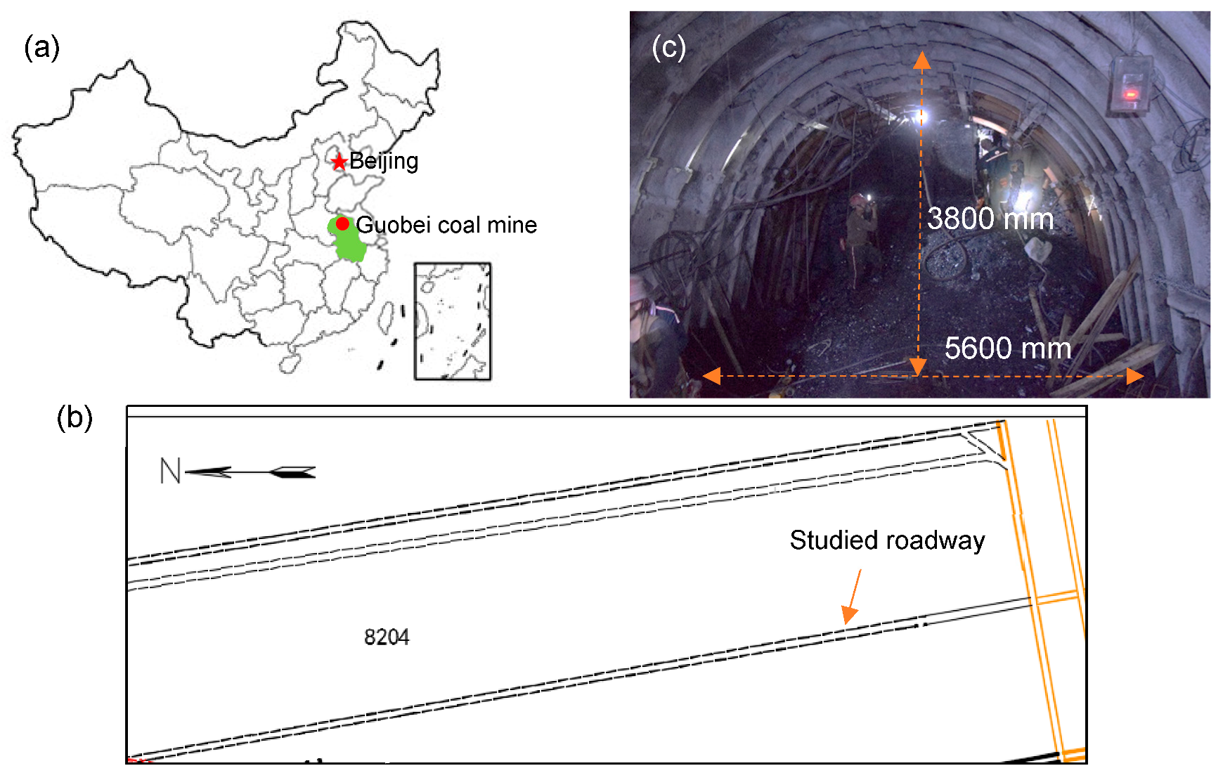
A project was conducted in Guobei coal mine, China (Figure 1a). The studied roadway is shown in Figure 1b. It was a conveyor roadway for transporting coal from the working panel of 8204. In terms of this working panel, the depth was around 700–750 m. The roadway was normally driven along the floor and arranged in the coal layer. Due to the previous complicated tectonic movement, the coal mass with low strength was full of fractures and cracks. When tunneling in such soft coal mass, collapse and spalling of working face normally occurred. The size of the original roadway is shown in Figure 1c. A conventional support strategy (i.e., U-shaped steel sets, rock bolts, and shotcrete) was designed and utilized (Figure 1c). However, large roadway convergence normally occurred at one to two months and most of the support structures failed.
2.2. Rock Mass Properties
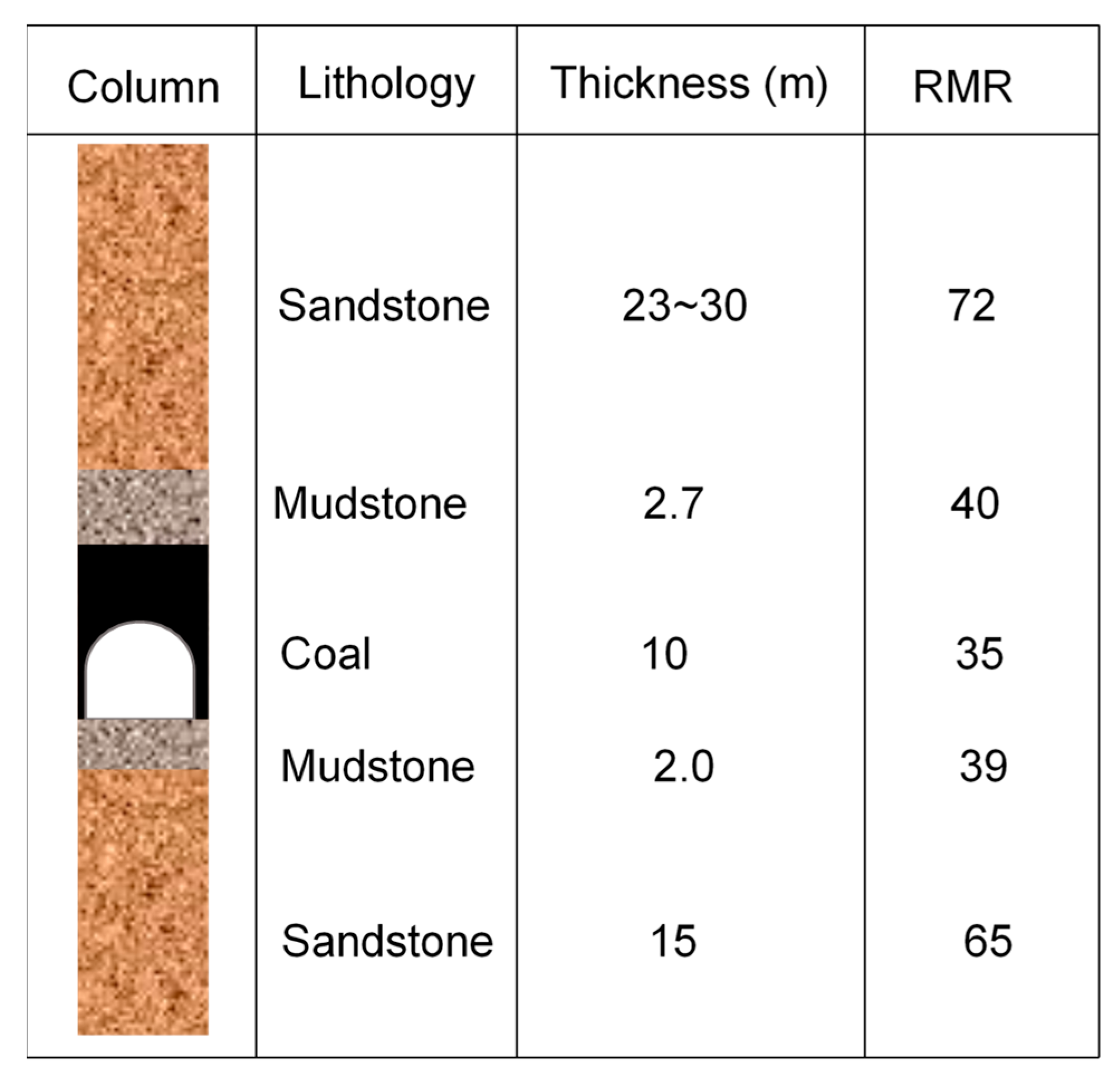
The rock mass properties affected roadway stability obviously. The stratigraphic column of lithology around roadway is shown in Figure 2. To characterize various lithological units, the rock mass rating (RMR) classification system and the geological strength index (GSI) were used. Based on the RMR values obtained from the field observations, the GSI value was then determined by empirical correlation [30]. According to the following typical equations [31,32,33] and intact rock properties such as compressive strength, the rock mass properties are shown in Table 1.
3. In-situ Measurement in the Roadway
3.1. Measurement Station Setting
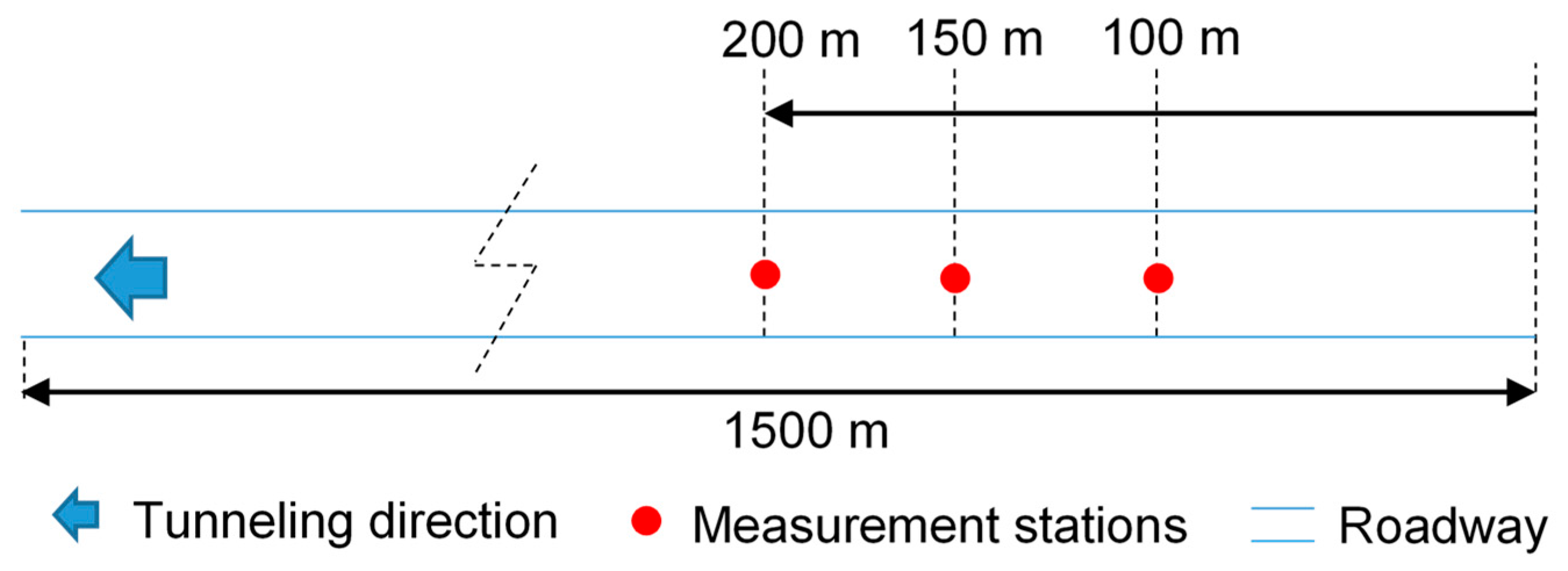
Three measurement stations were constructed and used for measuring the displacement of the roadway after excavation (shown in Figure 3). The monitoring points installed on the roadway profile. The flexible tape was used to measure the roadway cross-section convergences. To avoid the statistical error and scattered monitoring data, the average values collected from the three measurement stations in different monitoring points were used as the final in-situ measurements. In practice, before the roadway reached the large deformation, it had been maintained in advance in order not to affect its use, and therefore the displacement data on-site was accumulative deformation. It should be mentioned that the sidewalls of roadway suffered several re-excavations due to the large displacement, and the obtained monitoring data illustrated fluctuations of displacement to some extent.
3.2. Analysis of In-Situ Roadway Deformation
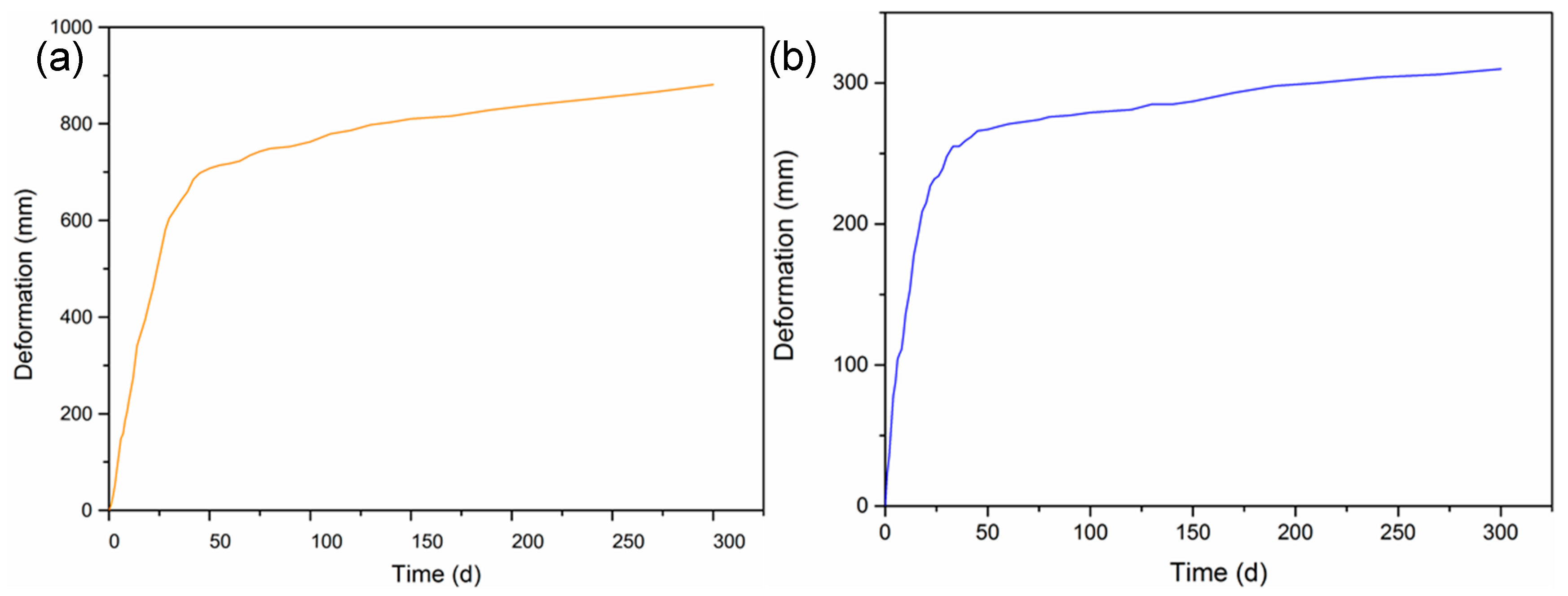
The in-situ measurements of roof-to-floor convergence and sidewall convergence are shown in Figure 4. It is clear that the deformation of the roadway exhibited rheological properties especially on sidewalls. After roadway excavation, the deformation on the roof and sidewalls increased evidently over time. The sidewall convergence was almost three times the roof-to-floor convergence. This is because the immediate floor is the relatively high-strength mudstone and its rheological behavior is not as obvious as the surrounding soft coal mass. The sidewall must be maintained and reinforced several times in its service life, which means that the high-rigidity support system cannot resist the rheological deformation of coal mass in the long-term. The described phenomenon showed that the soft coal mass was easily in rheology and caused roadway failure over time. To reveal the time-dependent behavior and failure mechanism of the roadway, a numerical model was performed.
4. Numerical Model Development and its Validation
4.1. Numerical Model Establishment
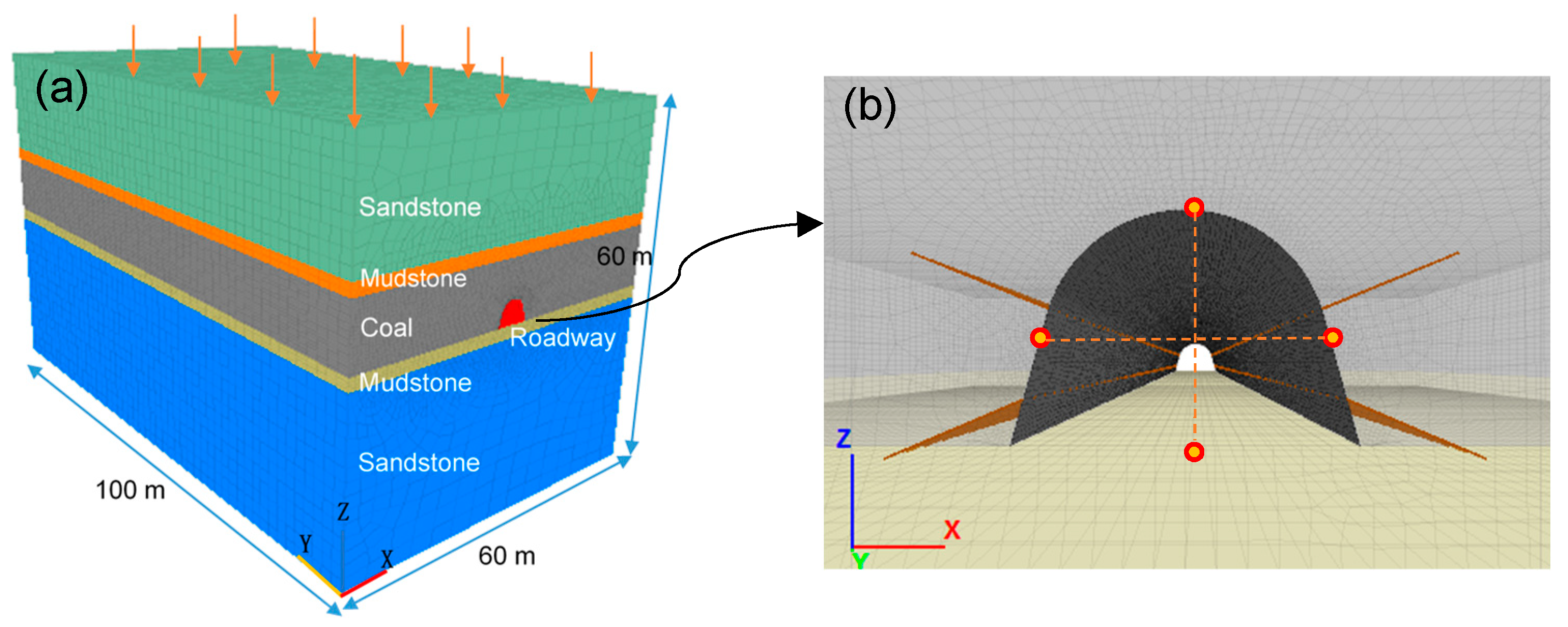
In this study, FLAC 3D was used to construct the model and simulate the time-dependent behavior of soft coal mass. This program is efficient and accurate for simulating rheological property of materials such as rock, coal, and composites, which has been verified by many researches. Specifically, according the field conditions of roadway such as size, lithology of rock mass and the strata thickness, the model in 3D was established (Figure 5a). It is noted that the boundary effect and element size normally have an effect on the accuracy of analysis. Therefore, the established domain is 10 times the roadway size in XZ plane and the length of the roadway was set as 100 m at YZ direction. The elements around roadway were divided by fine mesh, while the elements far away the roadway were set as larger size. The deformation of the model was monitored by setting monitoring points (depicted in Figure 5b). The bottom of the model was fixed and the left and right boundaries were set as roller boundaries. The applied vertical stress and horizontal stress to the model were gained from the literature about this coal mine [29].
4.2. The Properties of Support Materials
As the described above, in the field, the rock bolts, shotcrete, and U-shaped steel sets were applied to control the roadway. In FLAC 3D, the rock bolts and shotcrete were created by cable and shell elements, while the U-shaped steel sets were created by applying the equivalent elastic modulus on shotcrete. Thus, the sum of elastic modulus of shotcrete and U-shaped steel sets can be summarized by the following equation:
where E means the elastic modulus of all support materials, E0 is the modulus of shotcrete, Ag means the cross-sectional area of U steel set, Eg denotes the elastic modulus of steel, and Ac is the cross-sectional area of the shotcrete.
The support materials used in numerical model were given in Table 2.
4.3. Selection of Constitutive Models
Selecting a proper constitutive for rock mass is critical. According to the filed measurements, the rheological behavior of soft coal mass could not ignore. Thus, in this study, the Burger-creep viscoplastic model (CVISC) was used to simulate the time-dependent behavior of coal. The CVISC model has been successfully used in previous study [34]. It should be pointed out that the time-step in CVISC model in FLAC is real time, which is different from that in static analysis modes. Normally, the time-step in static modes is a virtual value representing steady-state condition. In terms of the constitutive models for the rock mass such as mudstone and sandstone, the typical Mohr-Coulomb (M-C) model was chosen, as the rheology in such strata is not obvious. Moreover, in CVISC model, the rheological parameters such as ηM, GM, ηK and GK are critical and they are obtained by referring the back-analysis method [34]. The rheological parameters used in this paper were given in Table 3.
4.4. The Deformation of the Roadway by JG Support
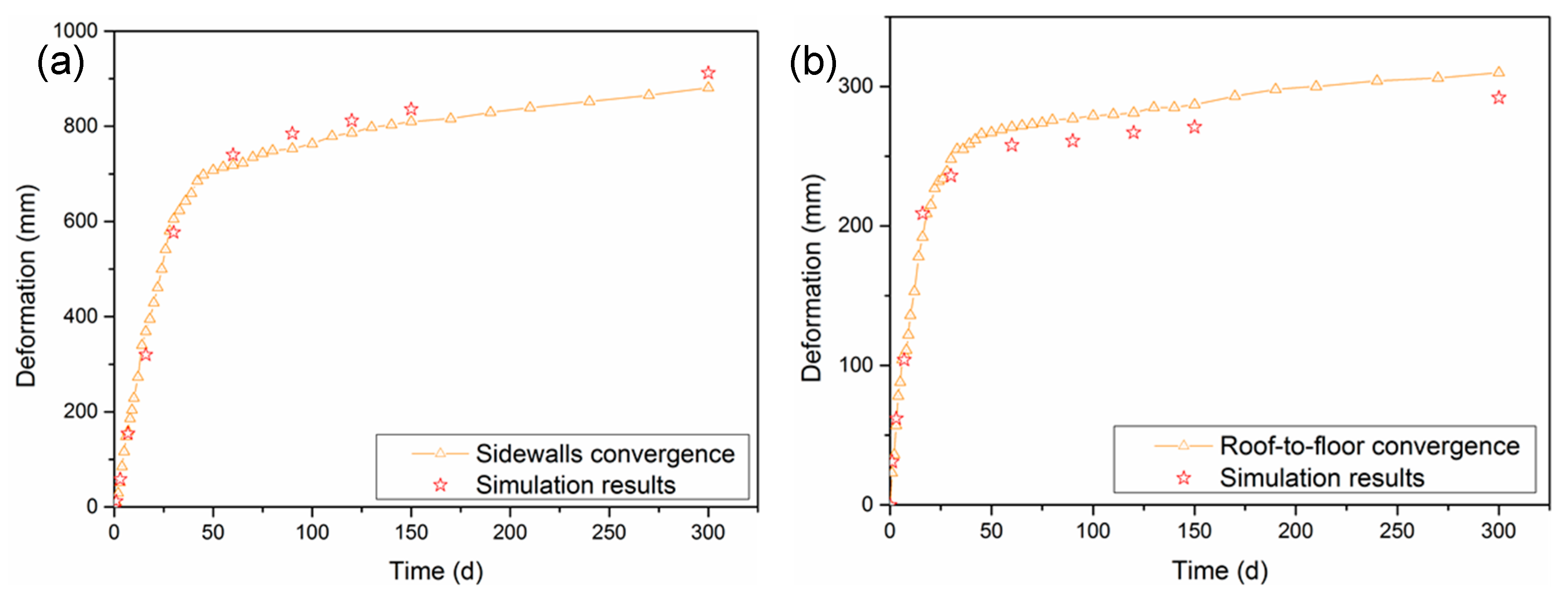
Based on the established model, a 300-day calculating period in the model was set and the simulation results of sidewall convergence and roof-to-floor convergence are illustrated in Figure 6. It can be seen that the simulated deformation (the red stars in Figure 6) of roadway are rather close to the field monitoring results. The calculated tendency is consistent with the filed results, which confirms that the established model with time-dependent behavior are reasonable.
5. The Analysis of Evolutionary Failure of Soft Coal Roadway
As described above, the accuracy of established model was confirmed. Hence, in this section, the stability of roadway was analyzed and discussed based on the validated numerical model. Specifically, the roadway deformation, stress states, and plastic zones around roadway were systematically investigated to reveal the failure mechanism of soft coal roadway with time-dependent behavior. Some monitoring results at various days (i.e., 3 days, 15 days, 30 days, 60 days, 150 days, 300 days) were chosen to compare and analyze.
5.1. The Time Dependent-Behavior of Roadway Deformation
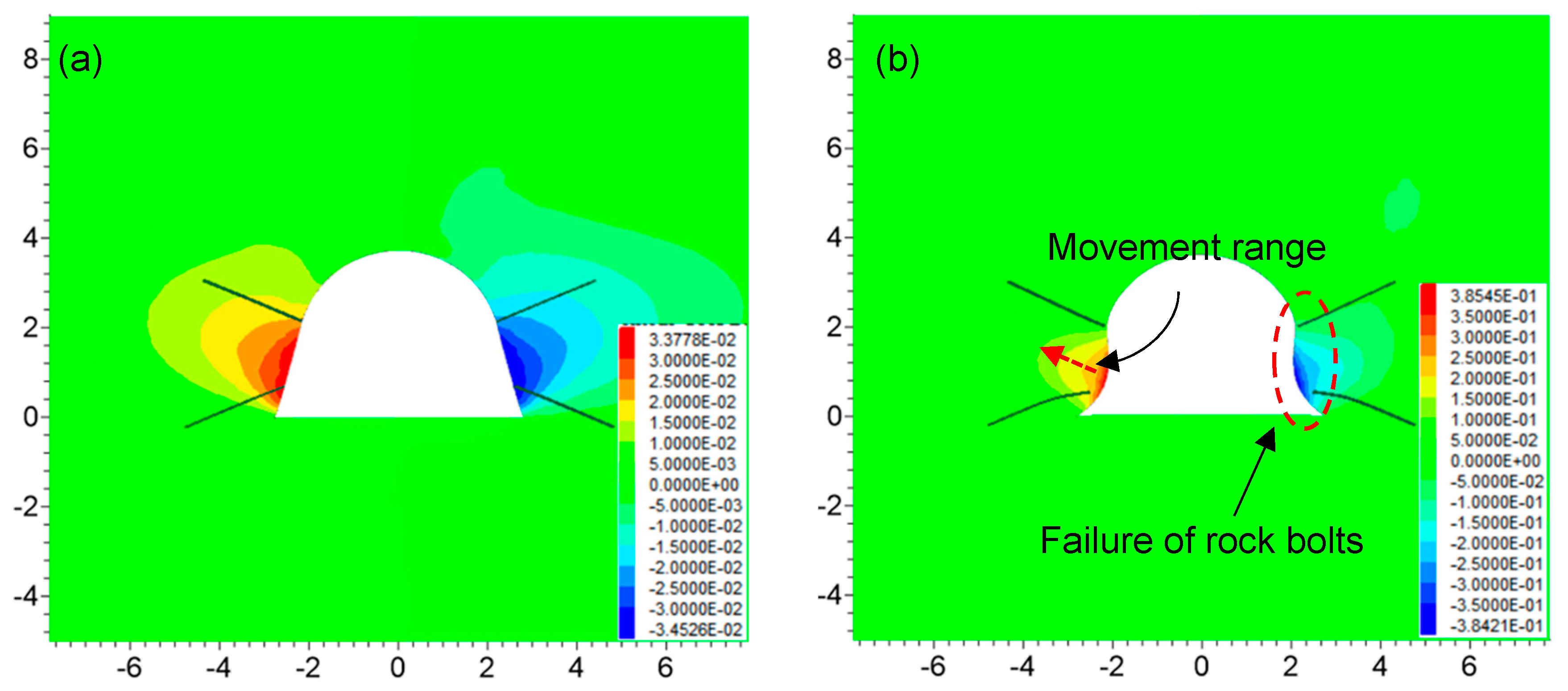
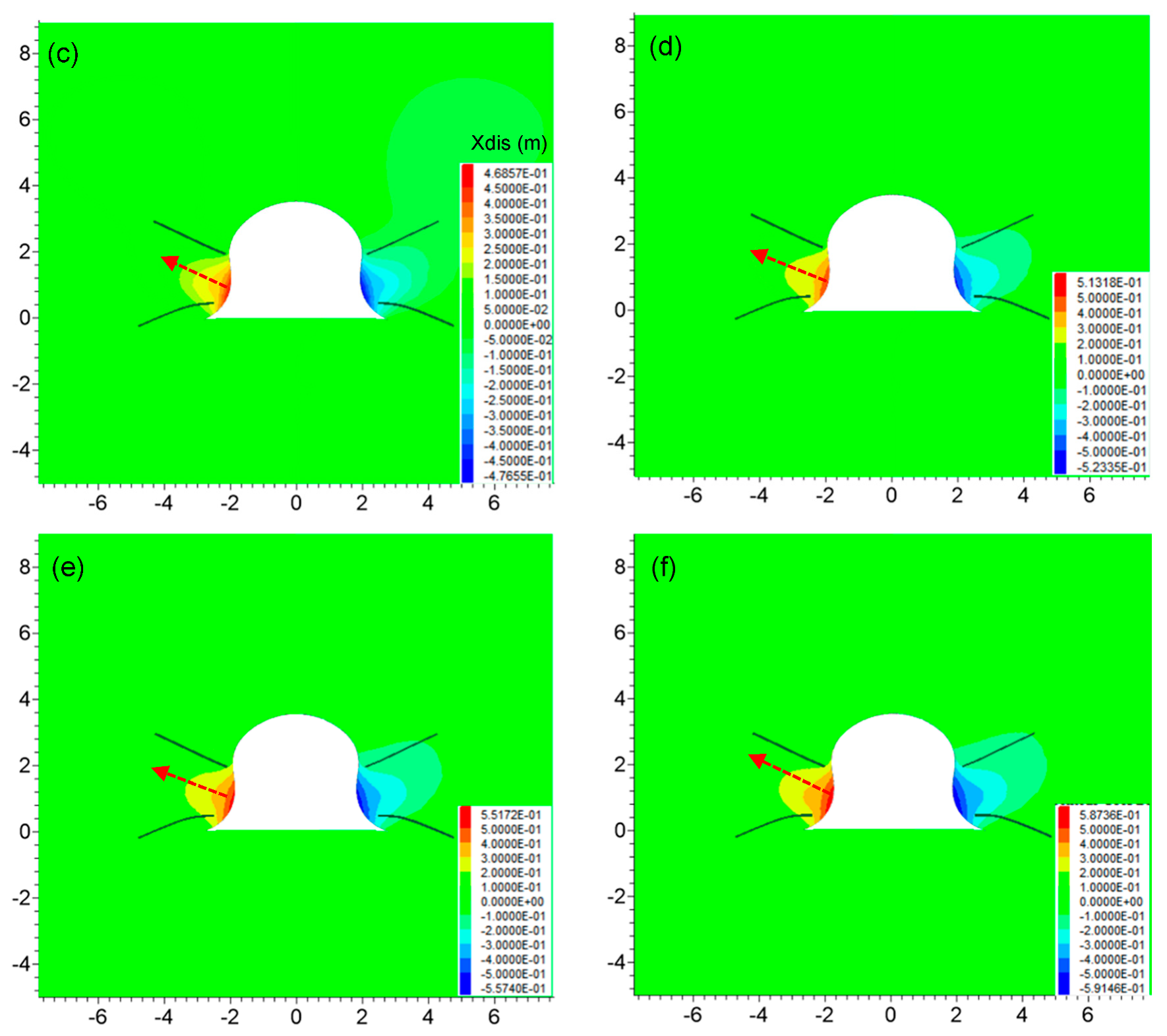
The horizontal roadway displacement with time is depicted in Figure 7. After roadway excavation (Figure 7a), the horizontal deformation was small and it was mainly caused by the instantaneous failure deformation of coal mass at the roadway surface. With the increase of time, the deformation sidewalls increased gradually, which was mainly composed of the rheological deformation and plastic-flow deformation of the coal mass (Figure 7b–f). Moreover, the deformation behavior of the roadway exhibited not only the increases of the displacement on the roadway surface but also the increase of movement range in coal mass (as indicated by the red dashed arrow). It can be clearly seen from Figure 7b that after 15 days, the rock bolts lost the use of reinforcement and completely failed due to the large sidewall extrusion of the roadway (shown by a red dashed circle). Thus, the roadway convergence was more serious over time.
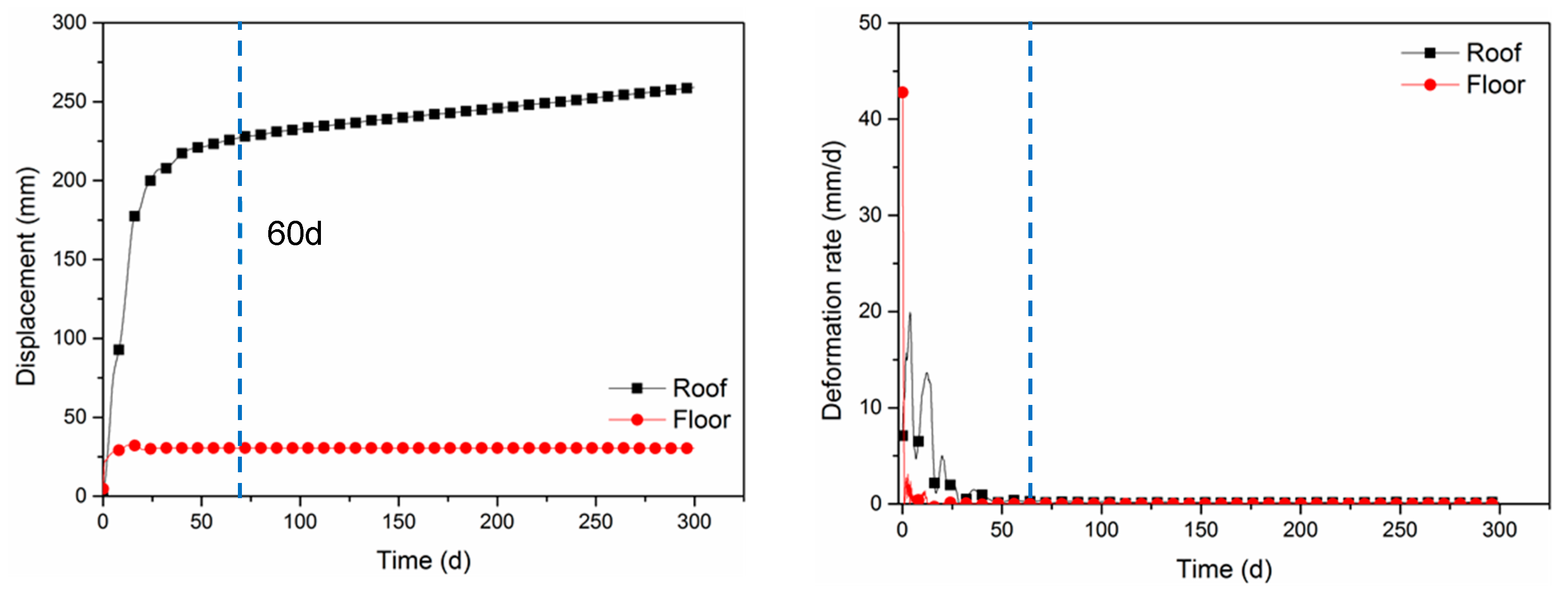
In addition, the displacement and deformation rate of the left and right sidewalls were obtained according to the monitoring results (depicted in Figure 8). As can be seen from Figure 8a, the deformation of the left and right sidewalls reached 457 mm and 463 mm, respectively (Figure 8a). However, the minimum requirement of sidewall deformation is 300 mm according to the engineering experience on-site. The roadway with such a large deformation cannot be used and therefore must be expanded and repaired several times. Furthermore, the maximum deformation rate of the two sidewalls reached 18.5 mm/d, and after about 60 days the deformation rate gradually decreased to a steady value which was larger than zero (Figure 8b). Therefore, it proved that there were two stages of rheology in the horizontal deformation of the roadway (i.e., decelerating rheology stage and uniform rheology stage).
The vertical displacement of the roadway with time is illustrated in Figure 9. Similar to the deformation in sidewalls, the roof deformation increased with time, and the movement range of coal mass around the roof also increased gradually (Figure 9a–f). As for the deformation on the roadway floor, the values were basically unchanging after roadway excavation. This is because the lithology in the floor is mudstone with relatively high strength and its failure can be regarded as plastic damage, while the immediate roadway roof is soft coal mass with serious rheological property and consequently the roof would be in rheology for a long time. Another phenomenon that should be pointed out is that the extrusion part in sidewalls (shown by the red dashed circle in Figure 9b) also demonstrated vertical displacements. The horizontal and vertical displacement in extrusion sidewalls formed a combined displacement with downward and inward movement to the roadway, which can accelerate the deformation of sidewalls. This is extremely adverse to the stability of the roadway and needs to be expanded and eliminated in time.
Further, the deformation and deformation rate of the roof and floor with time are shown in Figure 10. The maximum deformation on the floor was only 30 mm, while that on the roof was 260 mm (Figure 10a). From Figure 10a, the rheological deformation of the roof can be divided into two stages. The roof deformation showed the deceleration rheology in 60 days, while after 60 days that illustrated uniform rheology. According to Figure 10b, the maximum deformation rate of the floor was 42.5 mm/d, while that of the roof was about 20 mm/d. The deformation rate of the floor quickly decreased to zero and kept constant, which meant that there was almost no increase in deformation after roof failure at an early stage. By contrast, the deformation rate of the roof showed a slow reduction and then reached a constant value (greater than zero), indicating the coal mass in rheology would affect roadway stability severely.
5.2. The Evolutionary Stress Distribution Around the Roadway
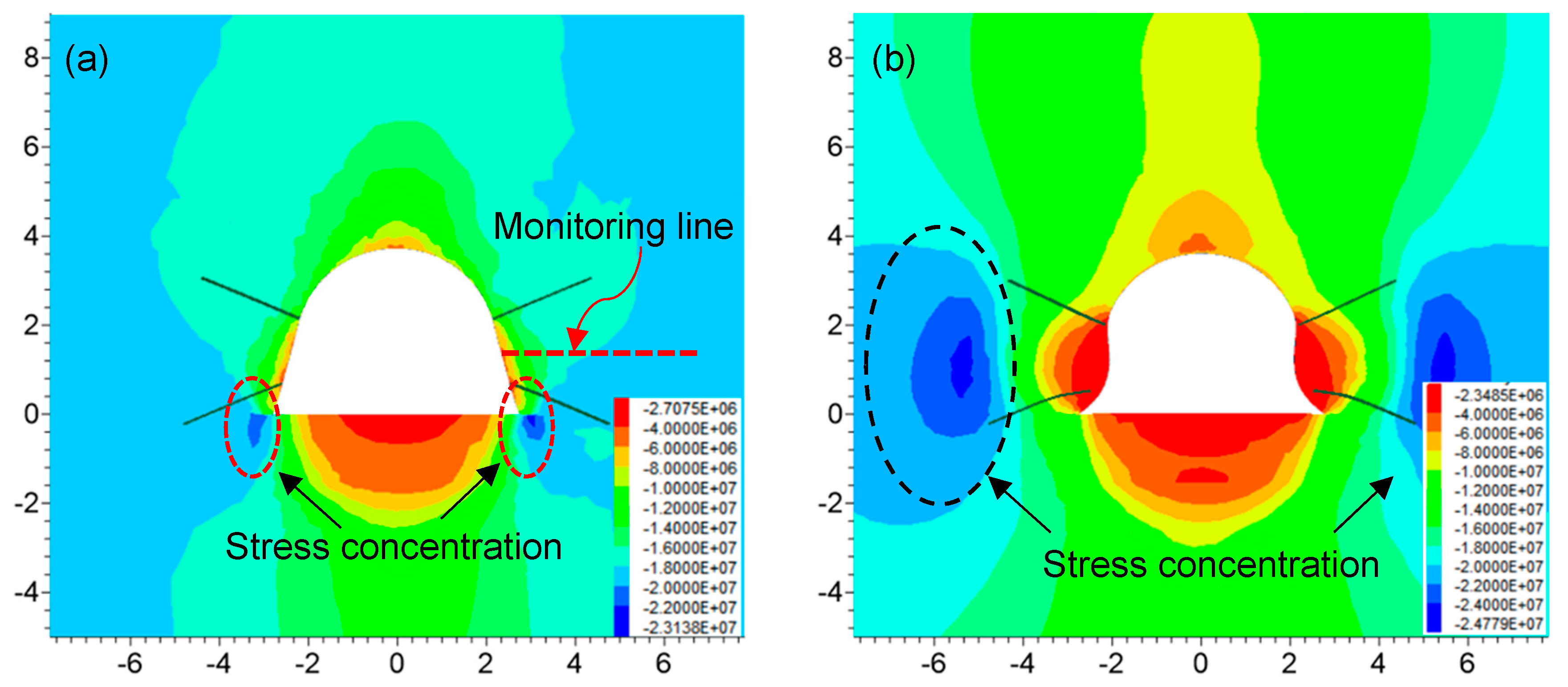
Around the roadway, the development of maximum principal stress with time is depicted in Figure 11. It is clear that there was a large stress relief zone around the roadway after excavation. Compared with the in-situ stress (about 19 MPa), the stress value near the roadway surface was far lower (Figure 11a–f). Due to the absence of support on the roadway floor, the stress relief area of the floor was large and it was almost unchanging with the increase of time. This is mainly because the floor had been completely damaged just after excavation and therefore the stress release of strata was complete. At the same time, it is noted that there were two stress concentration areas near the bottom corners of the roadway (as shown in the red dotted circle in Figure 11a), which was caused by the rigid support system on the roadway for undertaking and transferring the high stresses. However, with the increase of time and sidewall deformation, the size of these areas decreased and even disappeared. Generally, the stress relief zones of the roof and two sidewalls gradually increased (Figure 11a–f). Two stress concentration zones with high-stress values formed (as shown in the black dotted circle in Figure 11b) in the deep sidewalls of the roadway, and their range and size gradually changed with the increase of time (Figure 11c–f).
A monitoring line (depicted in Figure 11a) was arranged to reveal the maximum stress over time (1 day, 3 days, 7 days, 15 days, 30 days, 60 days, 150 days, 300 days). The results are illustrated in Figure 12. With the increase of time, the position of the monitoring points on the roadway surface gradually approached the origin of the horizontal coordinate axis, and the stress decreased significantly (as shown by the red dotted line arrow in Figure 12). That indicated roadway convergence and the failure of coal mass around the roadway surface. The peak stresses not only increased in coal mass but also transferred to the deep sidewalls over time (as shown by the blue dotted arrow in Figure 12). As shown by the black dashed arrow in Figure 12, the stresses in the coal mass in deep sidewalls also increased gradually with time. In this study, the ratio of peak stress to in-situ stress was defined as the factor of stress concentration. The results are summarized in Table 4. The maximum principal stress did not increase obviously within 3 days. The rheology of coal mass had little influence on the stress distribution of the roadway in 7 days. It can be considered that the maximum stress was still in-situ stress. After that, the stresses in coal mass subsequently exhibited time-dependent properties. At 60 days, the distance from the roadway surface to maximum stress in coal mass was relatively stable at 4.0 m and the corresponding stress concentration factor was 1.36. Overall, because of the rheological behavior of soft coal mass, the stress distribution around roadway was unfavorable for roadway stability.
5.3. The Development of Plastic Zone Around Roadway With Time
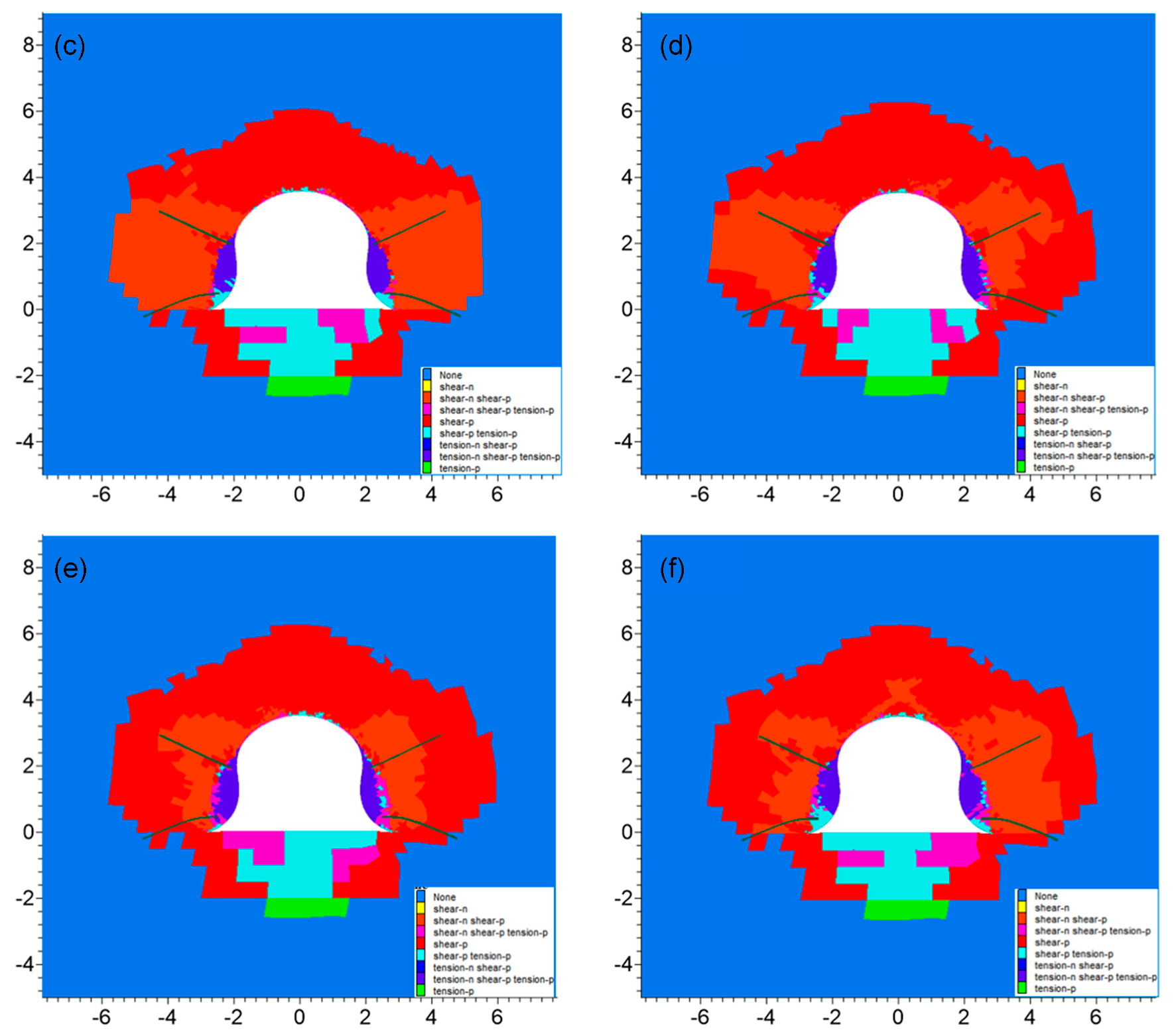
From Figure 13, it can be seen that there were some shear failures in the roof and two sidewalls of the roadway (Figure 13a). At the same time, and the roof also had a small number of tensile failures, while the majority failures of the floor were tensile damage. At 15 days, the extent of the plastic zone in sidewalls had completely exceeded the length of rock bolts, indicating the bolting support system has finally lost its function (Figure 13b). About 60 days later, the plastic zone of the roof and the two sides of the roadway tended to be stable (Figure 13c). With the increase of time, though the change of the plastic zone was not very obvious (Figure 13d–f), some areas around the roadway had a tendency to be in the plastic state, which was mainly affected by the long-term rheological behavior of coal mass. The development of maximum failure depth of the plastic zone is given in Table 5. In general, the characteristic of the maximum depth of plastic zone around roadway was “sidewalls > floor > roof” and the property of the development speed of the plastic zone was “sidewalls > roof > floor”.
6. Discussion and Suggestions
As analyzed above, the deformation behavior and failure mechanism in the soft coal roadway are different from the high-strength rock roadway. According to the literature [16,35], the squeezing failure normally occurred in the roadway with relatively high-strength rock or coal mass due to the dynamic high stresses (e.g., mining-induced stress) and the failure of support systems. The squeezing failure of such a roadway exhibited instantaneity of instability instead of time-dependent properties. As for this study of the soft coal roadway, the time-dependent behavior of the roadway is rather noticeable, which is closely related to evolutionary failure of the coal mass. Specifically, the evolutionary failure of the soft coal roadway includes the stress deterioration behavior and the development of plastic zone with time, which is different from the previous studies only focusing on final status of roadway [19,36].
In addition, based on the field measurement, the deep soft coal roadway illustrated quick and large rheological deformation in its service life (1 to 2 years). In comparison, the time-dependent deformation in a shallow rock tunnel is quite small in 5 to 10 years [37,38,39]. In terms of this, the previous research results in maintaining tunnel stability could not be applied to a soft coal roadway directly. Consequently, it is necessary to present some suggestions to keep the soft coal roadway stable.
In this study, grouting techniques are recommended to control the roadway stability. Improving the strength and integrity of soft coal mass is the basic way to restrain the rheological behavior and therefore to improve the roadway stability. Grouting as a reinforcement method can enhance the physical and mechanical properties of coal mass, which was confirmed by many successful engineering cases [40,41,42,43]. Therefore, the pre-grouting technique (e.g., horizontal jet grouting [44,45]) and delayed grouting are additionally proposed to control the time-dependent deformation of such a soft coal roadway.
Specifically, before roadway excavation, the jet grouting technique can be used to improve the strength of coal mass on the roadway profile and hence avoid the collapse and spalling of tunneling face [46,47,48]. Then the delayed grouting can be further applied to improve the integrity of surrounding coal mass of roadway after the installation of support structures (e.g., concrete steel sets, shotcrete, rock bolts, and cable bolts).
7. Conclusions
The aim of this research is to reveal the time-dependent behavior of deep coal roadway and its evolutionary failure mechanism. By a validated numerical model, the roadway deformation, stress distribution, and development of plastic zone around a soft coal roadway were systematically investigated and discussed. Some suggestions for controlling the rheological roadway were proposed. Specifically, a deep roadway with soft coal mass was selected as the studied area and its two-stage time-dependent deformation was first revealed (i.e., deceleration rheology and uniform rheology). The time-dependent 3D numerical model with the CVISC constitutive model was established considering the real properties of rock mass and support materials. By comparing the calculated results with field deformation of roadway, the model was validated, which confirms the model is reasonable. The deformation properties and failure mechanism of the soft coal roadway were systematically studied by the numerical model. The results showed that horizontal and vertical displacement in roadway exhibited rheological behavior and the conventional support system failed due to the large time-dependent deformation of the roadway. With the increase of time, the stresses around roadway deteriorated gradually and the plastic zone developed, which were negative for roadway stability in the long-term. The investigated failure mechanism of deep soft coal roadway was different from the rheological shallow tunnels and squeezing roadway. Based on the discussion, the grouting techniques including jet grouting and delayed grouting were further proposed for restraining the rheology of coal mass and improve roadway stability.
Author Contributions
Conceptualization, Y.S. and G.L.; methodology, J.X.; investigation, J.Z.; writing—original draft preparation, Y.S.; writing—review and editing, G.L., J.X., J.Z.; supervision, G.L.; funding acquisition, G.L. All authors have read and agreed to the published version of the manuscript.
Funding
This research was supported by the projects of “National Key Research and Development Program (2016YFC0600901)” and “National Natural Science Foundation of China (Grant No.51574224, 51704277)”.
Acknowledgments
The authors are grateful to Huaibei Mining (Group) Co. Ltd. Special thanks to the reviewers’ comments and editor’s work. Special thanks to Zuqi Wang for her encouragement and help.
Conflicts of Interest
The authors declare no conflict of interest.
References
- Wagner, H. Deep mining: A rock engineering challenge. Rock Mech. Rock Eng. 2019, 52, 1417–1446. [Google Scholar] [CrossRef] [Green Version]
- He, M.-C.; Xie, H.-P.; Peng, S.-P.; Jiang, Y.-D. Study on rock mechanics in deep mining engineering. Yanshilixue Yu Gongcheng Xuebao Chin. J. Rock Mech. Eng. 2005, 24, 2803–2813. [Google Scholar]
- Xie, H.; Gao, M.; Zhang, R.; Peng, G.; Wang, W.; Li, A. Study on the mechanical properties and mechanical response of coal mining at 1000 m or deeper. Rock Mech. Rock Eng. 2019, 52, 1475–1490. [Google Scholar] [CrossRef]
- Li, S.C.; Wang, H.T.; Wang, Q.; Jiang, B.; Wang, F.-Q.; Guo, N.-B.; Liu, W.-J.; Ren, Y.-X. Failure mechanism of bolting support and high-strength bolt-grouting technology for deep and soft surrounding rock with high stress. J. Cent. South Univ. 2016, 23, 440–448. [Google Scholar] [CrossRef]
- Xiao, T.; Wang, X.; Zhang, Z. Stability control of surrounding rocks for a coal roadway in a deep tectonic region. Int. J. Min. Sci. Technol. 2014, 24, 171–176. [Google Scholar] [CrossRef]
- Wilson, A.H. The stability of underground workings in the soft rocks of the coal measures. Int. J. Min. Eng. 1983, 1, 91–187. [Google Scholar] [CrossRef]
- Sun, Y.; Li, G.; Zhang, J.; Qian, D. Stability control for the rheological roadway by a novel high-efficiency jet grouting technique in deep underground coal mines. Sustainability 2019, 11, 6494. [Google Scholar] [CrossRef] [Green Version]
- Sun, Y.; Li, G.; Zhang, J. Developing hybrid machine learning models for estimating the unconfined compressive strength of jet grouting composite: A comparative study. Appl. Sci. 2020, 10, 1612. [Google Scholar] [CrossRef]
- Sun, Y.; Li, G.; Zhang, J. Investigation on jet grouting support strategy for controlling time-dependent deformation in the roadway. Energy Sci. Eng. 2020, 8, 1–8. [Google Scholar] [CrossRef] [Green Version]
- Shen, B.; King, A.; Guo, H. Displacement, stress and seismicity in roadway roofs during mining-induced failure. Int. J. Rock Mech. Min. Sci. 2008, 45, 672–688. [Google Scholar] [CrossRef]
- He, M. Physical modeling of an underground roadway excavation in geologically 45 inclined rock using infrared thermography. Eng. Geol. 2011, 121, 165–176. [Google Scholar] [CrossRef]
- Meng, B.; Jing, H.; Chen, K.; Su, H. Failure mechanism and stability control of a large section of very soft roadway surrounding rock shear slip. Int. J. Min. Sci. Technol. 2013, 23, 127–134. [Google Scholar] [CrossRef]
- Coggan, J.; Gao, F.; Stead, D.; Elmo, D. Numerical modelling of the effects of weak immediate roof lithology on coal mine roadway stability. Int. J. Coal Geol. 2012, 90–91, 100–109. [Google Scholar] [CrossRef]
- Pellet, F.; Roosefid, M.; Deleruyelle, F. On the 3D numerical modelling of the time-dependent development of the damage zone around underground galleries during and after excavation. Tunn. Undergr. Space Technol. 2009, 24, 665–674. [Google Scholar] [CrossRef]
- Kanik, M.; Gurocak, Z.; Alemdag, S. A comparison of support systems obtained from the RMR89 and RMR14 by numerical analyses: Macka Tunnel project, NE Turkey. J. Afr. Earth Sci. 2015, 109, 224–238. [Google Scholar] [CrossRef]
- Yalcin, E.; Gurocak, Z.; Ghabchi, R.; Zaman, M. Numerical analysis for a realistic support design: Case study of the Komurhan tunnel in eastern Turkey. Int. J. Geomech. 2015, 16, 5015001. [Google Scholar] [CrossRef]
- Gao, F.; Stead, D.; Kang, H. Numerical simulation of squeezing failure in a coal mine roadway due to mining-induced stresses. Rock Mech. Rock Eng. 2015, 48, 1635–1645. [Google Scholar] [CrossRef]
- Shen, B. Coal mine roadway stability in soft rock: A case study. Rock Mech. Rock Eng. 2014, 47, 2225–2238. [Google Scholar] [CrossRef]
- Mark, C.; Gale, W.; Oyler, D.; Chen, J. Case history of the response of a longwall entry subjected to concentrated horizontal stress. Int. J. Rock Mech. Min. Sci. 2007, 44, 210–221. [Google Scholar] [CrossRef]
- Kulatilake, P.H.S.W.; Wu, Q.; Yu, Z.; Jiang, F. Investigation of stability of a tunnel in a deep coal mine in China. Int. J. Min. Sci. Technol. 2013, 23, 579–589. [Google Scholar] [CrossRef]
- Li, W.; Bai, J.; Peng, S.; Wang, X.; Xu, Y. Numerical modeling for yield pillar design: A case study. Rock Mech. Rock Eng. 2014, 48, 305–318. [Google Scholar] [CrossRef]
- Kang, Y.; Liu, Q.; Xi, H. Numerical analysis of THM coupling of a deeply buried roadway passing through composite strata and dense faults in a coal mine. Bull. Eng. Geol. Environ. 2014, 73, 77–86. [Google Scholar] [CrossRef]
- Basarir, H.; Ferid Oge, I.; Aydin, O. Prediction of the stresses around main and tail gates during top coal caving by 3D numerical analysis. Int. J. Rock Mech. Min. Sci. 2015, 76, 88–97. [Google Scholar] [CrossRef]
- Li, G.; He, M.; Zhang, G.; Tao, Z. Deformation mechanism and excavation process of large span intersection within deep soft rock roadway. Min. Sci. Technol. 2010, 20, 28–34. [Google Scholar] [CrossRef]
- Tang, S.B.; Tang, C.A. Numerical studies on tunnel floor heave in swelling ground under humid conditions. Int. J. Rock Mech. Min. Sci. 2012, 55, 139–150. [Google Scholar] [CrossRef]
- Wang, Q.; Jiang, B.; Pan, R.; Li, S.C.; He, M.C.; Sun, H.-B.; Qin, Q.; Yu, H.C.; Luan, Y.C. Failure mechanism of surrounding rock with high stress and confined concrete support system. Int. J. Rock Mech. Min. Sci. 2018, 102, 89–100. [Google Scholar] [CrossRef]
- Coulter, S.; Martin, C.D. Effect of jet-grouting on surface settlements above the Aeschertunnel, Switzerland. Tunn. Undergr. Space Technol. 2006, 21, 542–553. [Google Scholar] [CrossRef]
- Shabanimashcool, M.; Li, C.C. Numerical modelling of longwall mining and stability analysis of the gates in a coal mine. Int. J. Rock Mech. Min. Sci. 2012, 51, 24–34. [Google Scholar] [CrossRef]
- Bai, Q.S.; Tu, S.H.; Wang, F.T.; Zhang, X.G.; Tu, H.S.; Yuan, Y. Observation and numerical analysis of the scope of fractured zones around gateroads under longwall influence. Rock Mech. Rock Eng. 2014, 47, 1939–1950. [Google Scholar] [CrossRef]
- Basarir, H.; Sun, Y.; Li, G. Gateway stability analysis by global-local modeling approach. Int. J. Rock Mech. Min. Sci. 2019, 113, 31–40. [Google Scholar] [CrossRef]
- Hoek, E.; Brown, E.T. Practical estimates of rock mass strength. Int. J. Rock Mech. Min. Sci. 1997, 34, 1165–1186. [Google Scholar] [CrossRef]
- Hoek, E.; Marinos, P.G.; Marinos, V.P. Characterisation and engineering properties of tectonically undisturbed but lithologically varied sedimentary rock masses. Int. J. Rock Mech. Min. Sci. 2005, 42, 277–285. [Google Scholar] [CrossRef]
- Hoek, E.; Carranza-Torres, C.; Corkum, B. Hoek-Brown failure criterion-2002 edition. Proc. NARMS TAC 2002, 1, 267–273. [Google Scholar]
- Hoek, E.; Diederichs, M.S. Empirical estimation of rock mass modulus. Int. J. Rock Mech. Min. Sci. 2006, 43, 203–215. [Google Scholar] [CrossRef]
- Guan, Z.; Jiang, Y.; Tanabashi, Y. Rheological parameter estimation for the prediction of long-term deformations in conventional tunnelling. Tunn. Undergr. Space Technol. 2009, 24, 250–259. [Google Scholar] [CrossRef] [Green Version]
- Cao, R.-H.; Cao, P.; Lin, H. A kind of control technology for squeezing failure in deep roadways: A case study. Geomat. Nat. Hazards Risk 2017, 8, 1715–1729. [Google Scholar] [CrossRef] [Green Version]
- Islam, M.R.; Shinjo, R. Numerical simulation of stress distributions and displacements around an entry roadway with igneous intrusion and potential sources of seam gas emission of the Barapukuria coal mine, NW Bangladesh. Int. J. Coal Geol. 2009, 78, 249–262. [Google Scholar] [CrossRef]
- Yang, F.; Zhang, C.; Zhou, H.; Liu, N.; Zhang, Y.; Azhar, M.U.; Dai, F. The long-term safety of a deeply buried soft rock tunnel lining under inside-to-outside seepage conditions. Tunn. Undergr. Space Technol. 2017, 67, 132–146. [Google Scholar] [CrossRef]
- Sharifzadeh, M.; Tarifard, A.; Moridi, M.A. Time-dependent behavior of tunnel lining in weak rock mass based on displacement back analysis method. Tunn. Undergr. Space Technol. 2013, 38, 348–356. [Google Scholar] [CrossRef]
- Sainoki, A.; Tabata, S.; Mitri, H.S.; Fukuda, D.; Kodama, J.-I. Time-dependent tunnel deformations in homogeneous and heterogeneous weak rock formations. Comput. Geotech. 2017, 92, 186–200. [Google Scholar] [CrossRef]
- Kang, Y.; Liu, Q.; Xi, H.; Gong, G. Improved compound support system for coal mine tunnels in densely faulted zones: A case study of China’s Huainan coal field. Eng. Geol. 2018, 240, 10–20. [Google Scholar] [CrossRef]
- Kang, Y.; Liu, Q.; Gong, G.; Wang, H. Application of a combined support system to the weak floor reinforcement in deep underground coal mine. Int. J. Rock Mech. Min. Sci. 2014, 71, 143–150. [Google Scholar] [CrossRef]
- Jiao, Y.Y.; Song, L.; Wang, X.Z.; Coffi Adoko, A. Improvement of the U-shaped steel sets for supporting the roadways in loose thick coal seam. Int. J. Rock Mech. Min. Sci. 2013, 60, 19–25. [Google Scholar] [CrossRef]
- Salimian, M.H.; Baghbanan, A.; Hashemolhosseini, H.; Dehghanipoodeh, M.; Norouzi, S. Effect of grouting on shear behavior of rock joint. Int. J. Rock Mech. Min. Sci. 2017, 98, 159–166. [Google Scholar] [CrossRef]
- Sun, Y.; Li, G.; Zhang, J.; Qian, D. Experimental and numerical investigation on a novel support system for controlling roadway deformation in underground coal mines. Energy Sci. Eng. 2019. [Google Scholar] [CrossRef] [Green Version]
- Sun, Y.; Zhang, J.; Li, G.; Wang, Y.; Sun, J.; Jiang, C. Optimized neural network using beetle antennae search for predicting the unconfined compressive strength of jet grouting coalcretes. Int. J. Numer. Anal. Methods Geomech. 2019, 43, 801–813. [Google Scholar] [CrossRef]
- Sun, Y.; Zhang, J.; Li, G.; Ma, G.; Huang, Y.; Sun, J.; Wang, Y.; Nener, B. Determination of young’s modulus of jet grouted coalcretes using an intelligent model. Eng. Geol. 2019, 252, 43–53. [Google Scholar] [CrossRef]
- Sun, Y.; Li, G.; Basarir, H.; Karrech, A.; Azadi, M.R. Laboratory evaluation of shear strength properties for cement-based grouted coal mass. Arab. J. Geosci. 2019, 12, 690. [Google Scholar] [CrossRef]
Figure 1.
The studied area and the conditions of the roadway; (a) the location of Guobei coal mine; (b) the location of studied roadway; (c) the support system used in the roadway.
Figure 1.
The studied area and the conditions of the roadway; (a) the location of Guobei coal mine; (b) the location of studied roadway; (c) the support system used in the roadway.

Figure 2.
Stratigraphic column of rock.

Figure 3.
The locations of measurement stations.

Figure 4.
Roadway convergence. (a) Sidewalls convergence; (b) roof-to-floor convergence.

Figure 5.
3D numerical model and enlarged roadway cross-section. (a) The 3D model; (b) the detailed roadway cross-section.
Figure 5.
3D numerical model and enlarged roadway cross-section. (a) The 3D model; (b) the detailed roadway cross-section.

Figure 6.
Comparison of field measurements and simulated results. (a) Sidewall convergence; (b) roof-to-floor convergence.
Figure 6.
Comparison of field measurements and simulated results. (a) Sidewall convergence; (b) roof-to-floor convergence.

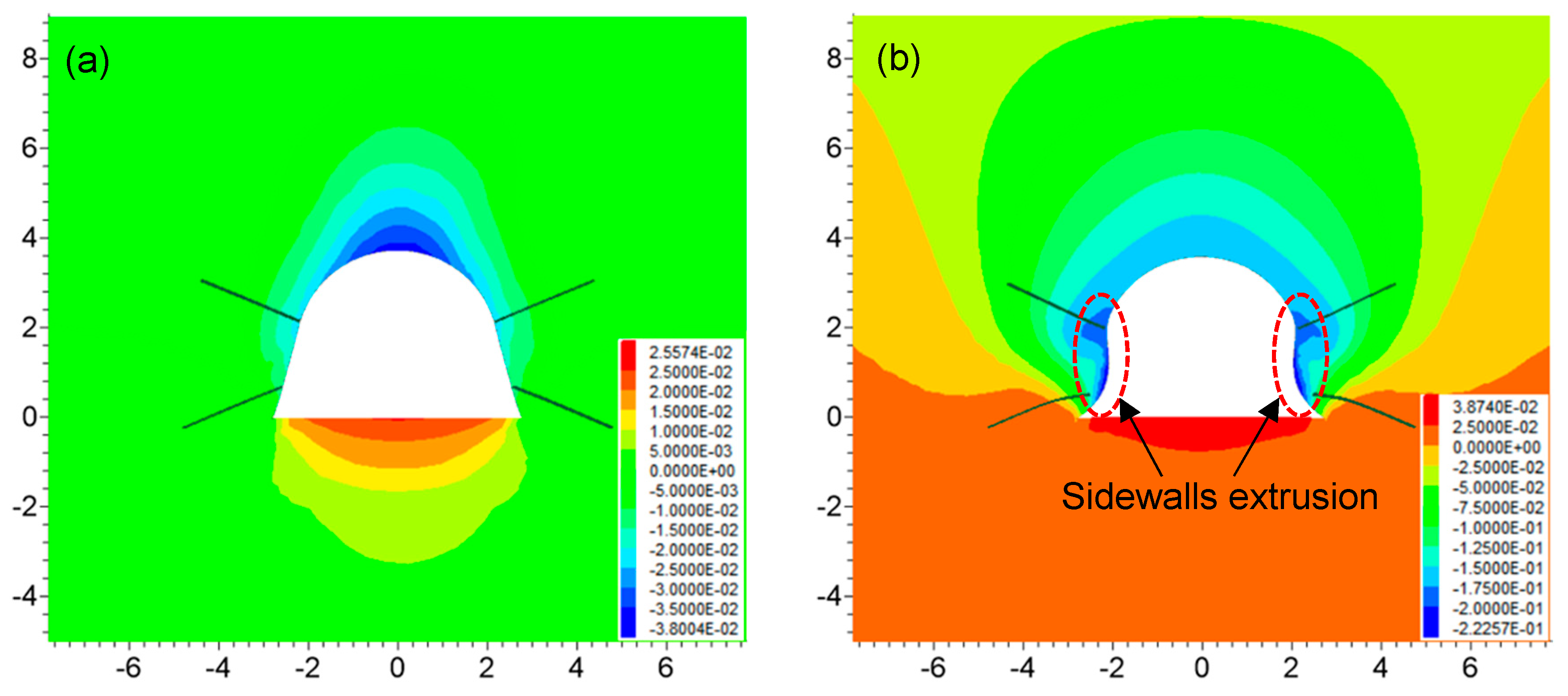
Figure 7.
The horizontal displacement of roadway with time (unit of the axis, m; legend of X displacement, m): (a) 3 days; (b) 15 days; (c) 30 days; (d) 60 days; (e) 150 d; (f) 300 days.
Figure 7.
The horizontal displacement of roadway with time (unit of the axis, m; legend of X displacement, m): (a) 3 days; (b) 15 days; (c) 30 days; (d) 60 days; (e) 150 d; (f) 300 days.


Figure 8.
The displacement and deformation rate of sidewalls. (a) Deformation of sidewalls; (b) deformation rate of sidewalls.
Figure 8.
The displacement and deformation rate of sidewalls. (a) Deformation of sidewalls; (b) deformation rate of sidewalls.

Figure 9.
The horizontal displacement of roadway with time (unit of the axis, m; legend of Z displacement, m): (a) 3 days; (b) 15 days; (c) 30 days; (d) 60 days; (e) 150 d; (f) 300 days.
Figure 9.
The horizontal displacement of roadway with time (unit of the axis, m; legend of Z displacement, m): (a) 3 days; (b) 15 days; (c) 30 days; (d) 60 days; (e) 150 d; (f) 300 days.


Figure 10.
The displacement and deformation rate of roof and floor. (a) Displacement; (b) deformation rate.
Figure 10.
The displacement and deformation rate of roof and floor. (a) Displacement; (b) deformation rate.

Figure 11.
The maximum principal stresses distribution around roadway with time (unit of the axis, m; legend of Maximum principal stress, MPa): (a) 3 days; (b) 15 days; (c) 30 days; (d) 60 days; (e) 150 d; (f) 300 days.
Figure 11.
The maximum principal stresses distribution around roadway with time (unit of the axis, m; legend of Maximum principal stress, MPa): (a) 3 days; (b) 15 days; (c) 30 days; (d) 60 days; (e) 150 d; (f) 300 days.


Figure 12.
The changes of maximum principal stress.

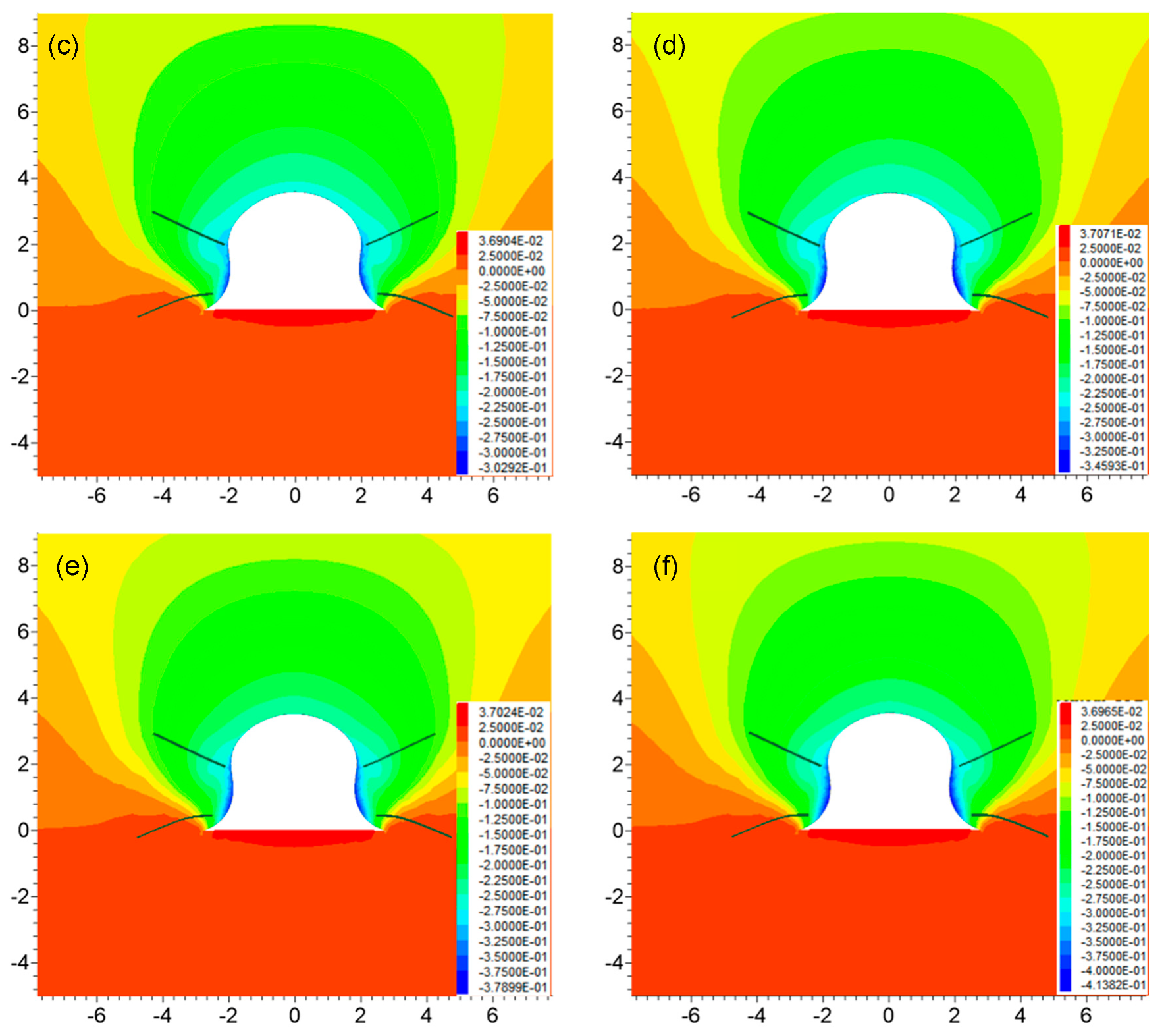
Figure 13.
The evolutionary plastic zone around roadway (unit of the axis, m; legend of plastic zone, status): (a) 3 days; (b) 15 days; (c) 30 days; (d) 60 days; (e) 150 d; (f) 300 days.
Figure 13.
The evolutionary plastic zone around roadway (unit of the axis, m; legend of plastic zone, status): (a) 3 days; (b) 15 days; (c) 30 days; (d) 60 days; (e) 150 d; (f) 300 days.


Table 1.
Rock mass properties.
| Rock Mass | GSI | Density, kg/m3 | Poisson’s Ratio | Cohesion, MPa | Friction Angle, | Tensile Strength, MPa | Deformation Modulus, GPa |
|---|---|---|---|---|---|---|---|
| Sandstone | 67 | 2690 | 0.22 | 3.45 | 42 | 0.79 | 12.5 |
| Mudstone | 35 | 2700 | 0.29 | 1.24 | 27 | 0.3 | 0.4 |
| Coal | 30 | 1420 | 0.39 | 0.98 | 24 | 0.15 | 0.50 |
| Mudstone | 34 | 2710 | 0.25 | 1.21 | 26 | 0.3 | 0.25 |
| Sandstone | 60 | 2680 | 0.21 | 2.85 | 40 | 0.51 | 8.9 |
Table 2.
The support materials used in numerical simulation.
| Parameters, Unit | Rock Bolt | U-shaped Sets | Shotcrete |
|---|---|---|---|
| Elastic modulus, GPa | 200 | 200 | 30 |
| Poisson’s ratio | 0.3 | 0.25 | 0.15 |
| Compressive strength, MPa | 400 | 400 | 40 |
| Tensile strength, MPa | 400 | 400 | 3.8 |
| Diameter/thickness, mm | 22 | 15 | 100 |
| Unit weight, kN/m3 | - | - | 24 |
| Length, mm | 2400 | - | - |
| Pre-tensioning, kN | 80 | - | - |
Table 3.
Back analysis results of rheological parameters of soft coal mass.
| ηM (MPa.h) | GM (MPa) | ηK (MPa.h) | GK (MPa) |
|---|---|---|---|
| 3.38e6 | 1.36e2 | 6.09e8 | 2.21e2 |
Table 4.
The concentration factor of maximum principal stress with time.
| Time (d) | 1 | 3 | 7 | 15 | 30 | 60 | 150 | 300 |
|---|---|---|---|---|---|---|---|---|
| Distance to peak stress (m) | 2.3 | 3.0 | 3.1 | 3.3 | 3.6 | 4.0 | 4.0 | 4.0 |
| Factor of stress concentration | 1 | 1 | 1.16 | 1.27 | 1.33 | 1.36 | 1.36 | 1.34 |
Table 5.
The statistics of the maximum depth of the plastic zone.
| Time (day) | 1 | 3 | 7 | 15 | 30 | 60 | 150 | 300 |
|---|---|---|---|---|---|---|---|---|
| The depth in roof (m) | 0.4 | 1.2 | 1.2 | 1.8 | 2.4 | 2.5 | 2.5 | 2.5 |
| The depth in floor (m) | 2.8 | 2.8 | 2.8 | 2.8 | 2.8 | 2.8 | 2.8 | 2.8 |
| The depth in sidewalls (m) | 0.4 | 1.2 | 2.6 | 3.2 | 3.4 | 3.6 | 3.6 | 3.6 |
© 2020 by the authors. Licensee MDPI, Basel, Switzerland. This article is an open access article distributed under the terms and conditions of the Creative Commons Attribution (CC BY) license (http://creativecommons.org/licenses/by/4.0/).
Share and Cite
MDPI and ACS Style
Sun, Y.; Li, G.; Zhang, J.; Xu, J. Failure Mechanisms of Rheological Coal Roadway. Sustainability 2020, 12, 2885. https://doi.org/10.3390/su12072885
AMA Style
Sun Y, Li G, Zhang J, Xu J. Failure Mechanisms of Rheological Coal Roadway. Sustainability. 2020; 12(7):2885. https://doi.org/10.3390/su12072885
Chicago/Turabian StyleSun, Yuantian, Guichen Li, Junfei Zhang, and Jiahui Xu. 2020. "Failure Mechanisms of Rheological Coal Roadway" Sustainability 12, no. 7: 2885. https://doi.org/10.3390/su12072885
Note that from the first issue of 2016, this journal uses article numbers instead of page numbers. See further details here.