Comprehensive Analysis of Trends and Emerging Technologies in All Types of Fuel Cells Based on a Computational Method


1
SUNCAT Center for Interface Science and Catalysis, Department of Chemical Engineering, Stanford University, 443 Via Ortega, Stanford, CA 94305, USA
2
Department of Technology and Innovation Management, School of Environment and Society, Tokyo Institute of Technology, Tokyo 108–0023, Japan
*
Author to whom correspondence should be addressed.
†
Present address: Department of Socio-Environmental Energy Science, Graduate School of Energy Science, Kyoto University, Yoshida-Honmachi, Sakyo-ku, Kyoto 606-8501, Japan.
Sustainability 2018, 10(2), 458; https://doi.org/10.3390/su10020458
Submission received: 29 December 2017
/
Revised: 2 February 2018
/
Accepted: 5 February 2018
/
Published: 9 February 2018
(This article belongs to the Special Issue Hydrogen Economy: Technology and Social Issue)
Abstract
:Fuel cells have been attracting significant attention recently as highly efficient and eco-friendly energy generators. Here, we have comprehensively reviewed all types of fuel cells using computational analysis based on a citation network that detects emerging technologies objectively and provides interdisciplinary data to compare trends. This comparison shows that the technologies of solid oxide fuel cells (SOFCs) and electrolytes in polymer electrolyte fuel cells (PEFCs) are at the mature stage, whereas those of biofuel cells (BFCs) and catalysts in PEFCs are currently garnering attention. It does not mean, however, that the challenges of SOFCs and PEFC electrolytes have been overcome. SOFCs need to be operated at lower temperatures, approximately 500 °C. Electrolytes in PEFCs still suffer from a severe decrease in proton conductivity at low relative humidity and from their high cost. Catalysts in PEFCs are becoming attractive as means to reduce the platinum catalyst cost. The emerging technologies in PEFC catalysts are mainly heteroatom-doped graphene/carbon nanotubes for metal-free catalysts and supports for iron- or cobalt-based catalysts. BFCs have also received attention for wastewater treatment and as miniaturized energy sources. Of particular interest in BFCs are membrane reactors in microbial fuel cells and membrane-less enzymatic biofuel cells.
1. Introduction
Fuel cells are efficient energy devices that convert chemical energy sources (fuels), typically hydrogen, directly to electricity [1,2]. Fuel reacts with oxygen from the air. When the fuel is hydrogen, water is the resultant product and thus the reaction is non-harmful. The main components are a catalyst and an electrolyte (see Figure 1). A catalyst, which facilitates reactions, is deposited on an electrode, or a catalyst itself is used as an electrode. There are two types of electrodes: anode (extracting electrons) and cathode (receiving electrons). The extracted electrons that separate from the fuel pass through an electronic device and the ions are conducted through an electrolyte to form an electric circuit. The electrolyte also serves to separate the anode and cathode to prevent mixing of the fuel and product (waste). However, the electrolytes do not require separation, such as in the case of some biocatalysts where the catalysts have selectivity to react with specific reactants. The merits of fuel cells include not only high energy efficiency but also that CO2 can be stored at a station that separates hydrogen from fossil fuels. The stored CO2 can be recycled as an energy carrier by hydrogenation based on sustainable energy [3,4]. Otherwise, CO2 can be deposited in storage sites, normally underground geological formations where CO2 emissions to the atmosphere will be prevented [5,6]. These methods can thus reduce the amount of emitted CO2. Although fuel cells are still expensive and lacking in sufficient applications research, there are certain commercial products that have potential to be significant to us. Extensive research is still being performed, totaling over 94,000 academic papers by 2016 and publishing approximately 9000 new papers per year. It is nearly impossible to read all of these papers and subdivided research areas are understood only by a few experts. Comprehensive overview of the entire research area is difficult even by reading review papers, as these papers can be subjective based on an authors’ research interests and thus typically focus on specific restricted topics. It is also difficult to compare different research areas that a researcher cannot analyze alone, and thus some quantitative data should be used for fair comparison. If it were not for comprehensive and objective data, opinions from certain experts could mislead both researchers and government agencies that set funding allocations for specific research topics.
Meanwhile, the bibliometrics method has been developed for examining a research area based on publication data [7,8,9]. For example, based on citation networks, publications can be divided into clusters that focus on similar topics [10]. The clusters include information such as average publication year, publication number and keywords in the abstract [11]. The information can provide insight into research areas that have the potential to be commercialized [12], overlooked but important research areas [13] and more. Bibliometrics is based on objective and comprehensive analysis of a sizable quantity of publication data. These numerical data also afford us the opportunity to successfully compare different research areas.
In this review, fuel cell research is analyzed objectively and comprehensively using bibliometrics. An interdisciplinary investigation of several types of fuel cell technologies was performed, including: solid oxide fuel cell (SOFC), polymer electrolyte fuel cell (PEFC) and biofuel cell (BFC) technologies. This review examines the current status of and emerging technologies in these fuel cell types and provides insight on future trends. The main goals of this review are to offer a fair comparison based on objective data, to provide an overview of all fuel cell technologies and to detect the hottest topics among all fuel cell types. Emerging technologies are introduced, with brief explanations and references to important papers in their respective research areas.
2. Materials and Methods
We collected bibliographic data from academic publications on fuel cell research. The academic papers, including the title, publication year, abstract and references, were retrieved from the Science Citation Index Expanded (SCI-EXPANDED) system, compiled by the Thomson Reuters Institute for Scientific Information (ISI). We used data collected with the query “fuel cell*” for analyzing SOFCs and PEFCs. BFC were investigated using data collected with the query “(“fuel cell*”) AND (enzym* OR microbial OR biological)) OR (“biofuel cell*”).” Data collection was carried out in May 2016.
Our analytical procedure is explained as follows [10]. (1) The data from academic papers were downloaded. (2) We constructed citation networks by treating the papers as nodes and the citations as links. According to a previous study, intercitation—also known as direct citation—is the best demonstrated approach for detecting emerging trends [14]. In the network analysis, only data from the largest graph components were used. (3) We eliminated data not linked to any other papers. (4) After extracting the largest connected component, the network was divided into clusters using the Newman’s algorithm topological clustering method, which extracts tightly knit groups of nodes [15]. Newman’s algorithm uses the following equation:
where Q is the independence of the module, M is the number of clusters, s is the given cluster, l is the number of links in the whole network, ls is the number of links between both nodes within cluster s and ds is the sum of the links of the nodes in cluster s. In Newman’s algorithm, the clusters are divided into subgroups to maximize Q. In Equation (1), the probability of random links is subtracted from the probability that reference links exist within cluster s. This algorithm identifies well-separated clusters in a research area. These procedures can be performed again for subdivided clusters. In Section 3, the main clusters that were classified once were examined as stand-alone trends. In the following sections, the clustering process was repeated on the main clusters for additional purposes. The topic of each cluster was confirmed by referring to keywords in the abstracts.
The publication count for clusters in each year were fitted using the Bass model to easily understand trends in different research areas [16,17]. The dataset used for curve-fitting excludes publications from 2016 since data from only a portion of that year were available and were thus not suitable for analyzing publication counts per year. The data curves without a peak top or with insufficient publication numbers are not suitable for Bass model analysis and thus did not have curves fit.
3. Main Research Areas and a Brief Explanation of Each Cluster
The number of publications collected for this review is approximately 94,000. The papers are divided into four main clusters: (I) SOFCs, (II) PEFC electrolytes, (III) PEFC catalysts and (IV) BFCs. The figures of each fuel cell type are schematically described in Figure 1 with related information. The perspective relationship among main clusters and their summarized information are shown in Figure 2 and Table 1, respectively.
3.1. Brief Explanation of SOFCs
The largest cluster is the SOFC research area (Cluster I, orange region in Figure 2). In SOFCs, a cathode passes electrons to oxygen and forms O2−. O2− percolates through an electrolyte and reacts with fuel at an anode, giving its electrons to the anode [20]. SOFCs operate at a much higher temperature, approximately 800–1000 °C, as O2− conductivity is too low at lower temperatures. The benefits of SOFCs are high energy efficiency and no requirements to use any scarce metals for the catalyst. The high temperature promotes reactions without expensive metals such as platinum. Instead, the high temperature causes oxidation and thermal stress, resulting in restricted material selection. For example, stainless steel cannot be used as the interconnection material due to oxidation at the elevated temperature, thus increasing cost. Moreover, the high operating temperature also imposes slow start-up and shut-down of SOFCs. Hence, SOFCs are primarily suitable for large-scale electricity generation with steady operation, a task which does not require starting and stopping. Existing research mainly focuses on lowering operating temperatures down to around 500 °C, i.e., intermediate-temperature SOFCs (IT-SOFCs) to overcome the above-mentioned limitations [20].
3.2. Brief Explanation of PEFC Electrolytes
The second largest cluster is the research area addressing proton exchange membranes in PEFCs (Cluster II, blue region in Figure 2). In PEFCs, an anode extracts an electron from hydrogen and generates a proton. The proton conducts through the polymer electrolyte membrane and reacts with oxygen at a cathode [21]. The best-known proton conducting electrolyte is Nafion, which is a fluorocarbon polymer composed of perfluorosulfonic acid group in a side chain. Nafion shows high proton conductivity with good chemical and mechanical stability. However, the proton conductivity severely decreases at low humidity because water is essential for the proton conduction mechanism [22,23,24]. Therefore, the operating temperature is under 100 °C in order to disturb water evaporation. The water management can negatively affect energy efficiency and increase costs. In addition, Nafion is relatively expensive, because the synthesis route requires several steps and its disposal is not eco-friendly due to its F content. This cluster focuses on alternative electrolyte polymers that have high proton conductivity even at low humidity with sufficient stability and are synthesized in a few steps without the use of F [25].
3.3. Brief Explanation of PEFC Catalysts
The third largest cluster is about catalysts in PEFCs (Cluster III, yellow region in Figure 2). PEFCs generally employ platinum as a catalyst, which is dispersed on C as Pt/C [26]. The highly acidic conditions provided by electrolyte polymers prevents the use of non-noble metals such nickel because such metals dissolve too easily. The moderate operating temperature (around 100 °C) compared to SOFCs suppresses catalytic activity. Therefore, Pt is used as a catalyst due to its high activity and stability but Pt is very expensive and its stability is not sufficient for long-term operation. Researchers have sought alternative catalysts that are not rare metals but that have high catalytic activity and sufficient stability [27,28]. In parallel, considerable effort has been devoted to reducing the amount of platinum by optimizing dispersion [29,30] or by mixing in other, more affordable elements [31]. As a benefit of moderate operating temperatures, PEFCs can start up and stop quickly. Thus, they are suitable for use as an energy source for portable devices, including automobiles.
3.4. Brief Explanation of Derivatives of PEFCs
Solid-state alkaline fuel cells (SAFCs) employ an anion exchange membrane for the electrolyte membrane that conducts hydroxide ions instead of protons [32]. Alkaline conditions render the oxygen reduction reaction more facile than acidic conditions due to electrokinetics [33]. Moreover, non-platinum-group metals can survive under alkaline conditions. Therefore, non-noble metals can be used as a catalyst, thus reducing cost. The parent of SAFCs is alkaline fuel cells (AFCs), which are generally composed of KOH or NaOH solutions as the electrolyte. The fatal drawback of AFC is the precipitation of carbonate/bicarbonate salts, because CO2 coming from the air can react with mobile cation such as K+ or Na+. The salts accumulate on the electrode and block sequential reactions [34]. SAFCs overcome this drawback because SAFCs do not include any mobile cations to form salts. The major challenge for SAFCs is to develop stable electrolyte membranes with sufficient hydroxide ion conductivity [25]. Anion exchange membranes can be also considered “polymer electrolytes” and several techniques in PEFCs can be used for SAFCs. Hence, SAFC technologies are included in the PEFC membrane cluster.
Direct methanol fuel cells (DMFCs) use methanol for fuel instead of hydrogen [35]. Methanol is much easier to store and transport than hydrogen, although other issues exist, such as methanol electrolyte crossover or CO catalyst poisoning. The properties of catalysts and electrolytes required for DMFCs are very close to those for PEFCs. Therefore, DMFC technologies are included in the PEFC membrane and catalyst cluster.
3.5. Brief Explanation of BFCs
The fourth largest cluster is about BFCs (Cluster IV, red region in Figure 2). BFCs consist primarily of enzymatic biofuel cells (EBFCs) [36] and microbial fuel cells (MFCs) [37], which respectively use isolated redox enzymes and living microorganisms as biocatalysts to generate electricity. The operating temperature is ambient so as not to deactivate the biocatalysts. EBFCs can generate power from sugars such as glucose from blood in the human body. The products are water and CO2, both non-harmful for humans. Therefore, EBFCs can be used as an intravital energy source (e.g., as an energy source for a cardiac pacemaker). On the other hand, MFCs generates electricity from various “dirty” fuels that are considered to be of little value, such as organic waste in sediments from wastewater treatment. High reactivity and high durability of biocatalysts is required for practical BFC applications. Electron transfer between the electrodes and biocatalyst active sites has been a challenge, because the distance between them is difficult to regulate to be close enough to conduct electrons [38]. There are two approaches to improve the loss. One is mediated electron transfer (MET), in which redox molecules or redox polymers shuttle electrons from biocatalytic active sites to the electrode surface. However, MET is not preferable because mediators are generally both harmful for environments and unstable and they sacrifice the maximum voltage obtainable from a fuel because they induce extra energy cascades between the biocatalysts and electrodes. The other approach is direct electron transfer (DET), from electrode to microorganisms or biocatalysts.
We analyzed the publication count per year in each cluster and fitted curves based on the Bass model (Figure 3). Based on the curve fitting, we consider the SOFC and PEFC electrolyte technologies to be in the mature phase. Meanwhile, publication counts in both PEFC catalyst and MFC research are increasing. In the following sections, we analyzed trends for each fuel cell type and we discuss emerging technologies.
4. Trends and Hot Research Topics: SOFCs
4.1. Perspectives on SOFCs
The SOFC clusters were further divided into five sub-clusters, as shown in Table 2. Based on the curve fitting of publication count per year (Figure 4), all research areas are considered to be in a mature phase except for Cluster I-E, “proton conducting oxide”. It is difficult to determine whether the phase of Cluster I-E is mature or increasing. These results suggest that SOFC technologies are sophisticated. The technology in each cluster is explained briefly below.
4.1.1. Cluster I-A: Oxygen Reduction on Cathode
Oxygen reduction reactions occur at cathodes with high activation energy [39]. Since the main trend in SOFCs is to achieve IT-SOFC, active cathodes, even at lower operating temperatures, has been sought. Oxygen gas arrives at the cathode and accepts electrons to be O2−, which conducts through the electrolyte. Therefore, the cathode material needs to hold mixed ionic-electronic conductivity properties, i.e., they should be Mixed Ionic-Electronic Conductors (MIECs). Basically, La1−xSrxMnO3−δ (LSM) was used for the cathode [40].
4.1.2. Cluster I-B: Oxide Ion Conducting Oxide
Yttria-stabilized zirconia (YSZ) is generally used as the electrolyte in SOFCs at high temperatures, around 1000 °C [41]. It has enough stability and sufficient O2− conductivity at these temperatures. However, YSZ is not suitable for IT-SOFCs because its conductivity is low at the ideal range of IT-SOFC operating temperatures. Cluster I-B mainly focused on Gd-doped ceria (GDC) [42] and LaGaO3 [43] in order to obtain high conductivity at lower temperatures. Sc2O3-doped ZrO2 (ScSZ) has also attracted attention for its high conductivity at IT [44].
4.1.3. Cluster I-C: Fuel Oxidation on Anode
Anodes oxidize fuels to H2O (and CO2 when the fuel is a hydrocarbon) through a reaction between fuels and O2−, releasing electrons from O2−. This reaction happens at triple-phase boundaries (TPBs), which are essentially an interface between electrolyte, electrode and gas. Anode materials should have high electronic conductivity and sufficient electrocatalytic activity, plus high chemical and thermal stability. Porous Ni-YSZ cermet is frequently used as an anode because it generally satisfies the above requirements—Ni has enough catalytic activity and electronic conductivity, while YSZ has sufficient ion conductivity and high stability [20]. Cluster I-C research examined the durability of Ni-YSZ from the microstructure viewpoint, primarily determined by the preparation methods employed [45,46,47]. The difference in thermal expansion coefficients between Ni and YSZ has also been a focus, as it can generate tiny cracks that result in polarization resistance.
4.1.4. Cluster I-D: Anode Tolerance
One of the challenges associated with Ni-YSZ is its tolerance for S poisoning and C deposition. Diverse fuels besides hydrogen are used for SOFCs, such as natural gas, alcohol and gasoline. C deposition on Ni-YSZ happens mostly via methane cracking, CO reduction and CO disproportion, which can block the active site of Ni [48]. Cu has been found to be inactive to C deposition, although its low melting point (1083 °C) is considered to be a problem. Several approaches to improve performance against C deposition exist, including mixing Ni and Cu and depositing metals on various electrolytes [49]. S can contaminate fuels, either as an impurity or intentionally to detect leakage. S poisoning happens over Ni and causes fuel cell performance degradation. S-tolerant anodes, such as La-doped SrTiO3, have also been investigated [50].
4.1.5. Cluster I-E: Proton Conducting Oxide
Instead of O2−-conducting electrolytes, proton-conducting oxides have gained interest for electrolytes in IT-SOFCs [51]. Proton-conducting ceramics, in particular perovskite-type oxides, show conductivity when exposed to hydrogen and/or water vapor. These materials are distinguished from the proton-conducting polymers operating under 100 °C that are typically used in PEFCs. As the most famous proton-conducting oxide, BaCeO3 has been intensively examined because of its excellent proton conductivity around 350–600 °C [52]. However, BaCeO3 decomposes when reacting with steam and acidic gases such as CO2 and SO2. Alternative proton-conducting oxides with sufficient stability are sought, for example, BaZrO3 and Ca-doped LnNbO4, even though their conductivity is not sufficiently high for practical use [52,53].
4.2. The Practical SOFC System
We focused on the following three clusters related to practical utilization: three-dimensional numerical simulation of SOFC stacks, micro combined heat and power (micro-CHP) and SOFCs with gas turbines (Table 3). 3D simulation can design actual form of SOFC stacks to optimize their performance (Cluster I-i) [54]. Micro-CHP is a residential-scale energy source for electricity and heat production and can thus be installed in individual houses or factories (Cluster I-ii) [55]. The benefit is that heat exhausted from SOFCs can be used for warming (e.g., a home or water) and transmission losses can be avoided, since the energy is produced at the point of use, resulting in high total energy efficiency. Cluster I-ii includes not only SOFC-based but also PEFC-based, CHP systems. SOFCs with gas turbines can generate electricity using exhausted gas from the SOFC via a gas turbine because of the high operating temperature of SOFCs (Cluster I-iii) [56]. These three clusters focus on optimization but the first one is about the SOFC stack itself and the latter two are about the overall system, integrated with other components. Based on curve fitting on publication count per year (Figure 5), Cluster I-i can be considered mature. The other two clusters are difficult to distinguish as mature or incremental. This indicates that SOFC stack technology is already optimized but combined systems require further investigation.
4.3. Emerging SOFC Technologies
As emerging SOFC technologies, we focused on the cluster whose average publication year is two years younger than that of the main SOFC cluster (Table 4).
Clusters I-1, I-2 and I-3 relate to the cathode materials for IT-SOFCs. Although decreased operating temperatures are desired to address several drawbacks, the low temperature deactivates catalysts. Active cathodes at lower temperatures have been particularly explored since a high oxygen reduction activation energy can severely decrease activity. In Cluster I-1, as promising cathodes for IT-SOFCs, double perovskites, including barium and cobalt described as MBaCo2O5+δ (M = La, Gd, Y, Pr, Nd, Sm, Eu, Tb, Dy, Ho), have been investigated due to their high oxygen vacancy concentration, high electronic conductivity and catalytic activity [57]. MBaCo2O5+δ (M = Gd, Pr, Nd, Sm) has been especially studied with intense interest.
In Cluster I-2, the stability of cubic perovskites BaxSr1−xCo0.8Fe0.2O3−δ (BSCFs) has been examined as a cathode for IT-SOFCs [39]. BSCFs have excellent phase stability above 900 °C. In the intermediate temperature range (500–900 °C), however, BSCFs suffer from slow decomposition of the cubic perovskite into variants with hexagonal stacking that are barriers to oxygen transport. The mechanism of this decomposition has been investigated, for example, in terms of CO2 influence.
Cluster I-3 focuses on the composite of YBaCo3ZnO7 catalysts and GDCs [58]. YBaCo3ZnO7 shows favorable electrochemical performance and an excellent thermal expansion coefficient as a cathode for IT-SOFCs, although it has a tendency to decompose after long-term operation at 600–800 °C. To improve stability, the Y in YBaCo3ZnO7 has been substituted by In or Ca at a non-stoichiometric ratio, otherwise the ratio of Co3Zn is changed with doping Gd or Al instead of Zn [58].
Cluster I-4 is theoretical research about LaMO3 (M = Mn, Fe, Co and Ni) cathodes, which have high activity for O2 reduction [59]. The reaction mechanism has been investigated, not only by ab initio calculations but also via experimental characterizations. The elementary steps in O2 reduction have been analyzed to confirm the rate-determining step, which provides important insights to improve catalytic activity.
Cluster I-5 discusses symmetrical SOFCs, in which the same electrode material is used for both anode and cathode [60]. Symmetrical SOFCs have attracted increasing attention due to their potential for improved thermomechanical compatibility of the electrolyte and the electrodes, their reduced fabrication cost and for their role in further cell maintenance.
Cluster I-6 is the research about diagnostic methods and degradation techniques, such as alternating current impedance measurements [61]. This cluster includes the modeling approach composed of the experimental parameters obtained from the above techniques. These approaches evaluate several degradations quantitatively and determine the critical degradation for the whole system, thus providing guidance to lengthen the system life cycle.
In Cluster I-7, double perovskite Sr2MgMoO6−δ anodes have been investigated to seek tolerance for S poisoning and C deposition [62]. They have mixed ionic-electronic conductivity and a high tolerance for S and C deposition. Several approaches have been performed, such as doping La onto the Sr-site to improve conductivity [20]. Substitution of Mg in Sr2MgMoO6−δ by Co, Ni and Fe provides high activity. However, these are unstable in highly oxidizing or reducing atmospheres [62]. Further research into Sr2MgMoO6−δ is required to determine that degradation mechanism.
Cluster I-8 focuses on yttrium-doped BaZrO3 as a proton-conducting oxide at high temperatures [52]. BaZrO3 has much more chemical stability than BaCeO3 although the proton conductivity of BaZrO3 is not enough high. The cause of the poor conductivity is derived from low conductivity in grain boundary regions coupled with the material’s poor sinterability. This means that if the poor sinterability is overcome, the material could be ideal for IT-SOFCs.
Cluster I-9 investigates Ca-doped LaNbO4 as the alternative proton-conducting oxide [53]. Although the conductivity is still too low for practical use, degradation due to CO2 and water vapor has been mostly circumvented.
All of these clusters have similar average publication years, circa 2012. This value is not recent in comparison with other technologies, such as PEFC catalysts and BFCs. This also suggests that SOFC technologies are sophisticated.
5. Trends and Hot Research Topics: PEFC Electrolytes
5.1. Perspectives on PEFC Electrolytes
The PEFC electrolyte clusters were further divided into five sub-clusters, as shown in Table 5. The curve fitting of publication count shows that only Cluster II-C, “SAFCs” and Cluster II-E, “Phosphoric acid-doped polybenzimidazole (PBI) membrane”, are between mature or incremental phases, while other research areas are in the mature phase (Figure 6). This suggests that PEFC membranes have already been developed and are very close to the application phase, whereas Clusters II-C and II-E still require further investigation. Each cluster is explained briefly below.
5.1.1. Cluster II-A: Organic/Inorganic Composites
Inorganic particles (e.g., zirconium phosphate [63,64,65] or silica [66,67]) are dispersed in organic polymers for improving two properties of electrolytes: methanol crossover and proton conductivity at low humidity [68]. In DMFC applications, one of the challenges is methanol crossover, where methanol permeates the electrolyte polymer and is not used as fuel. Inorganic particles within electrolytes can block methanol permeation, whereas H+ can conduct it. In addition, inorganic particles can absorb water molecules rather than organic polymers around the boiling point of water. Then, in some cases, organic/inorganic composites retain high proton conductivity under low humidity conditions. Otherwise, inorganic particles are considered to help the phase separation of polymer electrolytes and to form well-aggregated hydrophilic phases, thus facilitating H+ conduction [69,70]. Some solid acids, such as CsHSO4 and 12-phosphotungstic acid [71,72,73,74], show high proton conductivity under non-humidified conditions and have been investigated intensely, although they are generally water soluble and not suitable for practical use. Researchers in this cluster tested various combinations of inorganic and organic electrolytes to achieve the ideal properties.
5.1.2. Cluster II-B: Sulfonated Hydrocarbon-Based Polymers
Sulfonated hydrocarbon-based polymers have been investigated to overcome the drawbacks of Nafion: low proton conductivity under low humidity conditions, environmental harm due to F and high cost derived from multiple synthesis steps. Sulfonated hydrocarbon-based polymers do not include F and can generally be synthesized with a couple of steps [75]. Their H+ conductivity is sufficiently high under highly humidified conditions but normally decreases under low humidity conditions, rather than the conductivity of Nafion. Some polymers, such as block copolymers, show comparable H+ conductivity to Nafion under low humidity conditions because block copolymers can form well-separated hydrophilic and hydrophobic phases, which can retain H+ conductivity even under low humidity conditions [21,25].
5.1.3. Cluster II-C: SAFCs
SAFCs have attracted attention because various metals besides expensive platinum-group metals are also available [33]. This cluster includes research about direct alcohol fuel cells using SAFCs. The major issues with SAFCs include anion exchange membranes. The hydroxide ion diffusivity is less than the proton diffusivity in most media and thus a high concentration of the hydroxide ion is required to achieve sufficient conductivity (ion conductivity is proportional to the parameter multiplying ion concentration and ion diffusivity). In order to increase hydroxide ion concentrations, anion exchange membranes typically include quaternary ammonium groups. However, the nucleophilic hydroxide ion causes degradation of the quaternary ammonium group via two possible mechanisms, especially at high temperatures [76]. Attempts to improve stability and conductivity are still being made.
5.1.4. Cluster II-D: Nano-Structure of Nafion
Nafion is the most famous proton-conducting polymer electrolyte because of its high proton conductivity and high chemical stability. Based on experimental characterization and numerical calculations, research in this cluster has determined that the origin of high stability and conductivity is derived from phase separation to hydrophilic and hydrophobic phases [77,78]. This insight is applied to invent new polymer electrolytes, such as hydrocarbon electrolytes and anion exchange membranes.
5.1.5. Cluster II-E: Phosphoric Acid-Doped Polybenzimidazole Membranes
Phosphoric acid-doped PBI membranes have been investigated to improve H+ conductivity at low humidity [79]. Water molecules play an important role as a proton acceptor in proton conduction. PBI is introduced to polymers to be proton acceptors in lieu of water. Phosphoric acid has been doped to the polymer as a proton source, because phosphoric acid intrinsically has high proton conductivity without water molecules (i.e., without humidification). Actually, phosphoric acid-doped PBI membranes have good proton conductivity at high temperatures and low RH, especially when the doping level is high. However, phosphoric acid leaks out during long-term operation and thus conductivity gradually decreases. The old publication average year is because this cluster includes clusters related to phosphoric acid fuel cell (PAFC), which is the second oldest and the most commercialized type although the average year is still around ~2011 even if PAFC clusters are excluded.
5.2. The Practical PEFC System
PEFC electrolytes requires a humidity controller to retain high proton conductivity, which supplies water as steam using exhausted heat, i.e., the electrolyte needs to be managed by the whole system. Therefore, concerns with the overall system and the practical use of PEFCs are close to PEFC electrolytes and tend to be included in the PEFC electrolytes cluster rather than the PEFC catalysts cluster. Here, we analyze trends in the overall PEFC system. In addition, trends in micro-DMFC and AFC systems are included due to their similarity with PEFCs (Table 6).
In Cluster II-i, numerical simulations to optimize PEFCs themselves have been performed [56]. The mass transport of fuel gas and water is influenced by several factors: the micro-structure and thickness of the diffusion and catalyst layers, the mixing ratio of proton-conducting ionomers and catalysts and the produced water depending on the amount of electricity generated, etc.
Bipolar material, which contacts the electrode to supply fuel gas, to remove waste water and to collect electricity, was investigated in Cluster II-ii [80,81]. Bipolar material is important for overall efficiency and needs to be optimized to adjust to other components. Thus, optimizations of hybrid systems including PEFCs have been also demonstrated. This includes research about optimization of PEFC-powered vehicles [82] and power generation from PEFCs/ultracapacitors [83].
In Cluster II-iii, optimization of micro-DMFCs was performed by modeling and experimental tests in terms of mass transport, methanol concentration to minimize crossover and durability, etc. [84]. Micro-DMFCs are suitable as a portable energy source for laptop computers or mobile phones because methanol does not need stored in pressure-durable tanks like hydrogen does for PEFCs. This application for micro-DMFCs is best without pumps and fans for supplying fuel (known as passive DMFCs), in order to minimize size.
In Cluster II-iv, AFC systems were optimized by numerical simulations and experiments, especially in terms of the durability of electrodes such as silver or nickel [85]. The influence of CO2 on electrodes has also been examined for long-term operation [86].
Curve fittings show that these systems are almost mature, except for Cluster II-ii (Figure 7). The small publication count in Cluster II-iv implies that AFC systems have been already optimized completely and thus no longer receive attention. Otherwise, optimization has not been sufficient, which seems derived from the restricted AFC utilization, such as for energy sources in outer space. In addition, Cluster II-iv does not include research about SAFC systems and thus SAFC systems have not been optimized either, whereas PEFC and DMFC products seem to be optimized sufficiently. Only Cluster II-ii “hybrid system of PEFCs” is still on its way to optimization.
5.3. Emerging Research Topics Related to PEFC Electrolytes
As emerging technologies in topics related to PEFC electrolytes, we introduce clusters whose average publication year is two years younger than that of the main cluster about PEFC electrolytes (Table 7). Although Cluster II-1 “Fuel cell vehicles” is not exactly a PEFC electrolyte technology itself, it focuses on practical utilizations requiring the overall system, including electrolytes. As mentioned in Section 5.2, the overall PEFC system tends to be included in PEFC electrolyte clusters and thus Cluster II-1 was classified into PEFC electrolyte technologies. Cluster II-4 examines hybrid systems with other energy sources and PEFC systems, which is also included in the PEFC electrolyte cluster for the same reason. The catalyst layer is generally the same, meaning with an electrode composed of both Pt supported by carbon and Nafion, which is the interface between the gas supply space and the electrolyte membrane. The purpose of the catalyst layer is water management, to maintain enough humidity for high H+ conductivity but to remove extra water produced by the reaction in the PEFC itself so as not to disturb gas diffusion. This means that research regarding the catalyst layer is related to the overall PEFC system. Therefore, Cluster II-5, related to the catalyst layer, is included in the PEFC electrolytes cluster.
In Cluster II-1, PEFC-powered automobiles were presented. PEFCs are the most suitable energy source for automobiles because PEFCs can start up and stop quickly [87]. Energy optimization has also been investigated for hybrid systems of PEFCs using supercapacitors or batteries.
Cluster II-2 investigates anion exchange membranes for SAFCs (the main difference between Cluster II-2 and Cluster II-C is that Cluster II-2 does not include research on direct alcohol fuel cells using SAFC) [33]. The focused membrane is poly(arylene ether sulfone) functionalized with quaternary ammonium. Although the stability is insufficient for practical use, some degradation mechanisms of polymer were investigated to develop more stable polymers. One approach to enhance this property of the electrolyte emerges as a sub-cluster of Cluster II-2: the idea of block copolymers [25]. OH−-conductive block copolymers have also been synthesized; they can yield suitability high conductivity and stability. Other clusters were not evident with clear keywords. This implies that strategies to develop anion exchange membranes are not defined as “a phrase” and do not cite each other, except for block copolymers.
Cluster II-3 focuses on organic/inorganic composites which employ graphene oxides and carbon nanotubes (CNTs) as inorganics dispersed in electrolyte polymers [68]. Graphene oxide has a high surface area, with sufficient thermal stability and flexibility to be functionalized with the desired characteristics. Dispersed CNTs enhance the thermal and mechanical stability of polymers, although CNT has electron conductivity and the loading amount is restricted so as to not connect the CNT network (in cases where the CNT network is connected, the electrolytes cannot separate the two electrodes). CNTs can be also functionalized with various groups—such as protogenic groups—to support proton conductivity [68].
Cluster II-4 analyzed the cost of hybrid systems combining PEFCs and sustainable energy sources. One of the drawbacks of sustainable energy is high time-dependence, requiring other energy sources to supply electricity when sustainable energies are in short supply [88]. PEFCs are suitable for this purpose because they can quick start up and can produce electricity at the required scale with minimal loss of efficiency. This cluster suggests the optimal scale of the hybrid system in terms of the economics reflecting each district, such as for Iran [89].
Cluster II-5 analyzes the 3D microstructure of catalyst layers by tomography, especially using focused ion beam-scanning electron microscopy and nano-scale X-ray computed tomography [90]. These results help to optimize methods to fabricate catalyst layers and the mixing ratio of proton-conducting ionomers and catalysts.
The average publication year of Cluster II-2 is the most recent in Table 7. In other words, SAFC electrolytes are the hottest topic among PEFC electrolytes. The PEFC electrolyte research for cation exchange membrane in Table 7 is the research topic of Cluster II-3: nano-organic/inorganic composites using graphene oxides and CNTs, while others are related to research that integrates with other technologies. Clusters II-2 and II-3 should be considered as emerging technologies in PEFC electrolytes.
6. Trends and Hot Research Topics: PEFC Catalysts
6.1. Perspectives on PEFC Catalysts
The clusters of PEFC catalysts were further divided into three sub-clusters, as shown in Table 8. In Figure 8, the curve fitting of publication count shows that all clusters are not clearly in the mature phase, i.e., the publication counts of all research topics seem to be increasing. Especially, publications about Cluster III-B “oxygen reduction on cathodes” are increasing exponentially. We re-clustered this topic, resulting in two clusters and the change of publication counts for them in shown in Figure 9. It is noteworthy that Cluster III-B-a “N-doped graphene/CNT and non-precious metal (typically Co and Fe)” increases publication count each year at an exponential rate. Each cluster is briefly explained below.
6.1.1. Cluster III-A: Alcohol (Typically Methanol) Oxidation on Anodes
Direct alcohol fuel cells are fascinating because they do not require reforming of fuel and they are portable due to the liquid state of alcohol [91]. Methanol and ethanol are used as fuels and fuel cells driven by methanol (known as DMFCs) have been especially investigated. However, alcohol causes overpotential compared to hydrogen, due to slow kinetics. In addition, platinum is generally used as the catalyst for DMFCs but it suffers from CO (an intermediate in the methanol oxidation) poisoning over the Pt surface. This cluster attempts to improve its activity by loading Pt-based alloys (e.g., PtRu, PtPd and PtNi) [92,93], otherwise substituting support to graphene or CNT [94].
6.1.2. Cluster III-B: Oxygen Reduction on Cathodes
Platinum has been used as a catalyst for its high activity and stability. However, its high cost is a major obstacle for the commercialization of PEFCs. As shown in Table 9, there are two main approaches to reduce the cost.
Cluster III-B−a: N-doped Graphene/CNT and non-precious metals (typically Co and Fe)
Heteroatom-doped-graphene/CNT has catalytic activity for oxygen reduction without any metals [95]. As C is used for catalyst support, C-based material has high stability and electron conductivity for PEFC applications. Typically, N-doped graphene has been the focus because of its high reactivity. Other elements, such as B, P and S, have been tested to change the electronic structure of the catalyst [28]. Fe- and Co-based catalysts supported on N-containing C have been found to possess activity for oxygen reduction [96,97]. This class of catalyst has been increasingly investigated.
Cluster III-B−b: Pt-based alloys
Alloys composed of Pt and affordable metal(s) can maintain activity and stability but reduce the amount of Pt to decrease costs [98]. This cluster includes the core-shell approach, where non-precious metal forms the core and Pt covers its surface [99]. Since the surface is occupied by Pt, it can retain its activity and stability because the core does not come into contact with the acids. This approach can reduce the amount of waste Pt in the core. Moreover, the core material can affect the properties of the shell material [99].
6.1.3. Cluster III-C: Other Fuel Oxidation besides Alcohol on Anodes
Formic acid, hydrazine and sodium borohydride have been examined as fuels to be fed directly into a fuel cell. These fuels have sufficient energy density, comparable to methanol and are easy to keep in a liquid state for portable energy sources, although each has individual challenges for practical applications. For direct formic acid fuel cells, poisoning of the catalyst surface by intermediates of the reactions and crossover are challenges [26]. For direct hydrazine fuel cells, the high toxicity of hydrazine is the main problem, even though a method for storage has been developed to store hydrazine in a solid form [100]. Direct sodium borohydride fuel cells suffer from the same problem as AFCs because they include sodium [101].
6.2. Emerging Research Topics Related to PEFC Catalysts
As emerging technologies in topics related to PEFC catalysts, we introduce clusters whose average publication year is two years younger than that of the main cluster of PEFC electrolytes (Table 10).
Cluster III-1 focuses on Pt-based bimetallic catalysts for oxygen reduction [26,102]. The nanostructure of Pt, such as nanopolyhedra [103] or Pt-Pd nanodendrites gives high activity and high stability during PEFC operation [104]. The reason for this enhanced performance varies depending on each nanostructure and included metal. The Pt(111) surface is generally attributed to its high activity. The nanostructures are mostly considered to modify or facilitate exposing the Pt(111) surface [105].
In Cluster III-2, Pt on graphene was examined as a catalyst for DMFCs [106]. The beneficial properties of graphene for a support of the electrocatalyst are high surface area, high electronic conductivity and high thermal and chemical stability. Pt on graphene with or without modification by heteroatom (including oxygen, i.e., graphene oxide) shows enhanced activity for methanol oxidation [107].
Cluster III-3 focuses on Pd-based catalysts for the electrooxidation of alcohol, especially ethanol, in alkali media [108,109]. Ethanol is also focused on as a promising energy carrier for its liquid state and energy density, along with methanol. Pd is more active than Pt for ethanol oxidation in basic media. Pd is slightly more abundant on earth and cheaper than Pt although occasionally the cost of Pd is higher than that of Pt. Alloy composed of Pd and gold was examined to improve its activity and stability.
Cluster III-4 investigates Fe- or Co-based catalysts on N-doped graphene/CNT. The electronic structure changed by doped-N has influence on a metal catalyst. The synergistic effect of N-doped graphene on the catalyst enhances its activity for oxygen reduction [110,111]. These can be utilized for SAFCs because these catalysts are not suitable for acidic conditions. In some research in this cluster, metal-organic frameworks are also examined as precursors for these catalysts [112,113].
Clusters III-5, III-6 and III-7 are related to heteroatom-doped graphene/CNT as meta-free electrocatalysts for cathodes, even in acidic conditions. In Cluster III-5, extensive research about N-doped graphene/CNT is included [114]. In parallel in Cluster III-6, other heteroatoms, such as B, P and S, are doped into graphene/CNT to control the electronic structure of graphene/CNT [115]. In some cases, dual heteroatoms (N and B/P/S) are doped into graphene/CNT. Cluster III-7 focuses on the facile preparation of N-doped porous C material from N-rich ionic liquids or biomass [116].
The average publication year of Clusters III-4 and III-6 is more recent than 2014.0. Therefore, research in Clusters III-4 and III-6 should garner special attention as emerging technologies in PEFC catalysts.
7. Trends and Hot Research Topics: BFCs
7.1. Perspectives on BFCs
The BFC clusters were further divided into three sub-clusters, as shown in Table 11. The curve fitting of publication count shows that these clusters are clearly not in the mature phase, i.e., the increase rates of publication count are on the rise (Figure 10). In particular, the publication counts of Cluster IV-A “Direct electron transfer in anodes for MFCs” and Cluster IV-C “EBFCs” are increasing at an almost-exponential rate.
To investigate precisely, we divided these clusters in the same way to investigate trends of MFCs and EBFCs in more detail (Table 12 and Figure 11). Cluster IV-A is mainly composed of two sub-clusters. Cluster IV-B was separated into six sub-clusters. Cluster IV-C (EBFCs) is divided into four sub-clusters. The curve fitting of publication count for all these clusters is described in Figure 11. Figure 11a shows that both Cluster IV-A-a “Nanostructured C-supported anodes for MFCs” and IV-A-b “Electron transfer mechanisms in Shewanella and Geobacter” increase exponentially. Especially, IV-A-a has a more rapid rate than IV-A-b. In Figure 11b,c, Cluster IV-B-a “Optimizing MFC performance”, IV-B-c “Non-Pt cathodes for MFCs” and IV-B-d “Cell stack engineering for scale-up” are increasing rapidly, nearly exponentially. The others, IV-B-b “Bioremediation using MFCs”, IV-B-e “Electricity production from sediment and sulfide” and IV-B-f “Electricity production during wastewater treatment”, are in incremental or mature phases. Figure 11d indicates that the publication counts for Cluster IV-C-a “Practical demonstration in vivo” and IV-C-b “Enzymatic bioelectrocatalyst for EBFCs” are increasing. Note that the rate of IV-C-b is nearly exponential. IV-C-c “High current density and long durability of EBFCs” and IV-C-d “EBFCs with mediators or redox polymers” are in the mature phase. Particularly, the publication count of IV-C-d is in a phase of decrease. Each cluster is explained briefly below.
7.1.1. Cluster IV-A: DET in Anodes for MFCs
Cluster IV-A focuses on the facilitation of DET between electrode and biocatalysts in MFCs. One challenge in MFCs is the large ohmic loss caused by the long-distance cell membrane between the electrode and the microorganisms. DET from electrode to microorganisms in MFCs is achieved by employing metal-reducing bacteria that have membrane-bound redox proteins to transfer electrons. The research on DET comprises the following two topics.
Cluster IV-A-a: Nanostructured C-supported anodes for MFCs
Along with other applications in other fuel cell types, nanostructured C materials (graphene, CNT, etc.) have been used for anodes in MFCs [36,117]. They have good electron conductivity and their unique structure can be an effective collector of electrons from microbes that have membrane-bound redox to transfer electrons to the electrode directly.
Cluster IV-A-b: Electron transfer mechanisms in shewanella and geobacter
7.1.2. Cluster IV-B: Overall System and Other Components of MFCs
Cluster IV-B investigates the overall performance of MFCs from the viewpoint of cathodes, cell stack design, separators, fouling, substrates (fuel) and more. Details are below.
Cluster IV-B-a: Optimizing MFC performance
MFC performance has been optimized for practical applications by mathematical modeling and by the use of power management systems [121]. The membrane reactor focus also includes the study of membrane bioreactors (MBRs), explained in more detail in Section 7.2.
Cluster IV-B-b: Bioremediation using MFCs
This cluster does not mainly focus on electricity production but on bioremediation using MFCs [122], primarily denitrification [123] and the decolorization of azo dyes [124]. This cluster also includes studies about algae use as an energy source in MFCs with purpose of generating electricity.
Cluster IV-B-c: Non-Pt cathodes for MFCs
Generally, Pt is used for cathodes in MFCs although it is expensive. In addition, the solution used for BFCs is around neutral pH, not suitable for Pt to exhibit its activity. More active and affordable cathode materials for MFCs are sought in this cluster. Well-studied candidates are metal complexes (such as iron phthalocyanine) [125], manganese (MnO2) [126], activated C with polytetrafluoroethylene (PTFE, as binder) [126] and N-doped nanostructured carbons [127].
Cluster IV-B-d: Cell stack engineering of for scale-up
The MFC cell stack has been examined for scaling-up in Cluster IV-B-d [128]. Anodes should generally be protected from O around the cathode by the ion exchange membrane, Nafion [129]. However, the strong acidity of Nafion is not preferable for microorganisms and thus alternative electrolyte membranes are still being sought. Research about mass transport and fouling in separators is included. The assessment of MFC performance based on electrochemical impedance spectroscopy has also been investigated [130].
Cluster IV-B-e: Electricity production from sediment and sulfide in seawater
Electricity can be generated from sediment [131] or sulfide [132] in seawater using MFCs (sulfide oxidation can generate electricity), which also serves the role of bioremediation. Practical operation in the ocean has also been demonstrated in this cluster.
Cluster IV-B-f: Electricity production during wastewater treatment
The most significant use of MFCs, electricity production during water treatment, was studied in this cluster [37]. Various substrates included in wastewater, such as sludge [133] and livestock feces [134], have been shown to be capable of generating electricity. The average publication year here is the oldest among MFC research.
7.1.3. Cluster IV-C: EBFCs
EBFCs employs only an enzyme for biocatalysts, which is extracted from microorganisms. Therefore, the current density (per volume) of EBFCs is much higher than that of MFCs although the enzymes cannot be regenerated like MFCs. The high current density is suitable as a power source for an actual device. Cluster IV-C was divided into four topics as follows.
Cluster IV-C-a: Practical demonstration in vivo
EBFCs were practically demonstrated in vivo for living rats [135,136], insects [137] and more [138]. The EBFCs tested are small in size and wearable. A functionalized contact lens with an EBFC fueled by tears is also investigated in this cluster, explained in more detail in Section 7.2.
Cluster IV-C-b: Enzymatic bioelectrocatalyst for EBFCs
Several biocatalysts for anodes and cathodes are tested here. In general, anodes use glucose oxidase [139] and the cathode is Pt [140] or a multicopper oxidase such as laccase [141,142], bilirubin oxidase [143], or polyphenol oxidase [144]. A biocatalyst with high stability and reactivity has been sought. Especially when biocatalysts are immobilized on a cathode, the reaction on the cathode is selective, thus an electrolyte membrane is not required to disturb fuel cross-over [145,146]. As a trend, membrane-less EBFCs have received focus to minimize EBFC size and the suitable biocatalysts for membrane-less EBFCs have been examined.
Cluster IV-C-c: High current density and long durability of EBFCs
The bottleneck of EBFCs is to achieve high current density per volume and long durability [147]. DET in EBFCs are effective to reduce ohmic loss, in which electrons directly transfer from enzyme active sites to the electrode and eliminate the extra energy cascade which decreases electron voltage obtained from the EBFC. In addition, operating without mediators can extend the fuel cell lifetime because mediators do not survive for a long time [38]. C-based nanomaterials are employed for electrodes to collect electricity. Membrane-less EBFCs are also promising to minimize size, i.e., to increase current density. These topics have been investigated in this cluster by fabricating EBFCs to optimize cell design.
Cluster IV-C-d: EBFCs with mediators or redox polymers
MET has played an important role in EBFC research for a long time because its performance normally exceeds that of DET. This cluster includes research about various mediators and the immobilization of enzymes in redox-active polymers [148]. However, in order to overcome the bottleneck of EBFCs as mentioned above, MET has been receiving less attention and its publication count per year is decreasing as shown in Figure 11d.
7.2. Emerging Research Topics Related to BFCs
As emerging technologies of topics related to BFCs, we introduce clusters whose average publication year are two years younger than that of the main cluster of BFC technologies (Table 13).
Cluster IV-1 is about MBRs, which filter wastewater by an electrically conductive mesh attached with MFC cathodes [149]. The cathode catalyzes organic wastes on the mesh to generate electricity. Several attempts to integrate MFC-MBRs for wastewater treatment have been demonstrated, effectively treating the water at low cost. Feasibility and performance improvements are still being investigated.
In Cluster IV-2, N-doped nanostructured C is tested as a cathode for MFCs [150]. An ideal cathode catalyst should be scalable, durable and cost-effective. However, the Pt generally used for cathodes is too expensive and thus seeking alternative catalysts has been a hot topic. Among several candidates including non-noble metal and biocatalysts, N-doped C material have attracted much attention. This should be an application of developed catalysts as PEFC cathodes, which might mean more sophisticated catalysts in the future for PEFC cathodes will continue to be applied.
Cluster IV-3 focuses on EBFCs for contact lenses. Miniature-EBFCs can generates electricity from ingredients in human tears [151]. They can be applied for functional contact lenses with direct (invisible for others) displays, yielding biomedical devices for continuous fitness status and/or health care monitoring.
Cluster IV-4 focuses on Flavin adenine dinucleotide (FAD)-dependent glucose dehydrogenases (GDH) as anodes for membrane-less EBFCs [152]. Glucose oxidase is sensitive to oxygen and produces toxic H2O2. Alternatively, FAD-dependent GDH has been examined because it has relatively lower redox potential and is insensitive to oxygen, as compared to glucose oxidase. The combination of nanostructured C for catalyst support has also been investigated.
Cluster IV-5 is the research about MFCs on paper [153]. Paper is simple, low-cost, portable and disposable for analytic/diagnostic devices. MFCs on paper can produce electricity for the devices, suitable for resource-limited and remote regions, one-time point-of-use and point-of-care tests.
These clusters in Table 13 are all more recent than 2014.0, totally different from other types of fuel cells. As such, all of these clusters should be considered as emerging technologies.
8. Discussion
As an overall trend of fuel cell research, technologies regarding SOFCs and PEFC electrolytes are in the mature phase and technologies about PEFC catalysts and BFCs are receiving increased attention. Comparing average publication year of the emerging technologies in the overall types of fuel cells, even frontier research of individual components in SOFC technologies are not recent. This suggests that SOFCs are sophisticated technologies and could be assumed as the closest to application. The reason that PEFC catalysts have attracted attention is that the cost reduction for Pt catalysts has not yet been achieved. Research interests has been bolstered by heteroatom-doped graphene/CNT for metal-free catalysts or supports for Fe- or Co-based catalysts. The removal of Pt from the system can be also achieved by employing SAFCs, a trend in which publication counts are increasing. Therefore, as an overall trend in PEFC research, concerns for cutting the cost of Pt have been revived by the above new technologies. Meanwhile, BFCs have garnered much attention for wastewater treatment (MFCs) and miniaturization (MFCs and EBFCs). Especially, MBR/MFCs and membrane-less EBFCs seem key to fostering interest.
For SOFCs and PEFCs, even overall system research that should be performed after fundamental research of each component seems to be mostly in the mature phase (Figure 5 and Figure 7). To be precise, hybrid systems with other systems such as SOFC/gas turbines and PEFC/ultracapacitors require more investigations, although cell stack designs for SOFCs and PEFCs themselves have already been optimized. The total publication count of PEFC system optimization is much larger than that of SOFCs (Table 3 and Table 6). This means that more effort has been devoted to optimizing PEFCs than SOFCs. This could be because PEFCs have more components, such as water management, than SOFCs. Some clusters in BFCs focused on overall system optimization although the cluster size (publication count) is not as large as that of SOFCs or PEFCs. We could not detect a cluster for SAFC overall system research. The absence of this research may be because no representative electrolyte exists in the research regarding anion exchange membranes such as Nafion in cation exchange membranes, which have the potential to determine operating conditions, i.e., the entire design. However, a systematic design can provide guidance on the ideal properties of SAFC electrolytes and thus should be performed.
Although fundamental research on SOFC and PEFC electrolytes receives less attention currently, this does not mean that their inherent challenges have been solved. SOFCs still require a decrease in operating temperatures to approximately 500 °C so that relatively cheap stainless steel can be used as the interconnection material and so that quick start-up and stop become possible. Nafion is still primarily used for electrolytes in PEFCs and thus a severe decrease in proton conductivity at low RH and its high cost remain as challenges. Breakthroughs are necessary to inspire these research fields.
We focused on the interaction between emerging technologies listed in Table 7, Table 10 and Table 12 regarding PEFC electrolytes, PEFC catalysts and BFCs, respectively, because the recently developed technologies in each of these areas may not be applied to the other research areas. SOFCs have not been a research focus because the materials used are too different because of large differences in the necessary operating conditions. When comparing cation and anion exchange membranes, a cluster about organic/inorganic composites for SAFC electrolytes was not identified. Recently developed inorganics, especially and functionalized graphene/CNT, could be good candidates for enhancing stability and OH− conductivity in SAFCs. In BFCs, although we detected a cluster that focuses on “N-doped nanostructured carbons as cathodes in MFCs”, the clusters about “Fe- or Co-based on N-doped graphene/CNT” or “other heteroatom-doped graphene/CNT” were not found. Moreover, these approached were not detected in EBFCs. These approaches are likely of use for BFCs.
9. Conclusions
An analysis based on a citation network was performed for categories of fuel cells to detect hot areas of current research. The interdisciplinary comparison among all fuel cell types shows that the trends in SOFCs and PEFC electrolytes are likely in the mature phase, while PEFC catalysts and BFCs have both received recent attention. Even the practical systems for SOFCs and PEFCs have been sophisticated, which means these two types of fuel cells are each very close to commercialization. However, the operating temperature of SOFCs still needs to be decreased to enable the use of relatively cheap stainless steel as the interconnection material and to make quick start-up and stopping possible. As for PEFC electrolytes, Nafion is normally used but it suffers from a severe decrease in proton conductivity at low RH and a high cost. Breakthroughs are necessary to inspire these research fields. Meanwhile, recent research on PEFC catalysts has focused on ways to reduce the cost of the Pt catalyst. Two promising emerging technologies are heteroatom-doped graphene/CNT for metal-free catalysts or supports for Fe- or Co-based catalysts. In BFC research, wastewater treatment using MFCs and miniature MFCs and EBFCs are the focus of recent investigation. In particular, MBR/MFCs and membrane-less EBFCs are two exciting emerging technologies.
Acknowledgments
Part of this research was financially supported by the following project: Comprehensive scenario analysis for prospects and bottleneck of hydrogen energy in future energy system (FY2016-FY2017) in the program of Advancement of Hydrogen Technologies and Utilization Project, New Energy and Industrial Technology Development Organization (NEDO).
Conflicts of Interest
The authors declare no conflict of interest. The founding sponsors had no role in the design of the study; in the collection, analyses, or interpretation of data; in the writing of the manuscript and in the decision to publish the results.
References
- Steele, B.C.H.; Heinzel, A. Materials for fuel-cell technologies. Nature 2001, 414, 345–352. [Google Scholar] [CrossRef] [PubMed]
- Bullen, R.A.; Arnot, T.C.; Lakeman, J.B.; Walsh, F.C. Biofuel cells and their development. Biosens. Bioelectron. 2006, 21, 2015–2045. [Google Scholar] [CrossRef] [PubMed]
- Wang, W.; Wang, S.P.; Ma, X.B.; Gong, J.L. Recent advances in catalytic hydrogenation of carbon dioxide. Chem. Soc. Rev. 2011, 40, 3703–3727. [Google Scholar] [CrossRef] [PubMed]
- Jia, J.; Qian, C.X.; Dong, Y.C.; Li, Y.F.; Wang, H.; Ghoussoub, M.; Butler, K.T.; Walsh, A.; Ozin, G.A. Heterogeneous catalytic hydrogenation of CO2 by metal oxides: Defect engineering—Perfecting imperfection. Chem. Soc. Rev. 2017, 46, 4631–4644. [Google Scholar] [CrossRef] [PubMed]
- Jacobson, M.Z. Review of solutions to global warming, air pollution, and energy security. Energy Environ. Sci. 2009, 2, 148–173. [Google Scholar] [CrossRef]
- Boot-Handford, M.E.; Abanades, J.C.; Anthony, E.J.; Blunt, M.J.; Brandani, S.; Mac Dowell, N.; Fernandez, J.R.; Ferrari, M.C.; Gross, R.; Hallett, J.P.; et al. Carbon capture and storage update. Energy Environ. Sci. 2014, 7, 130–189. [Google Scholar] [CrossRef]
- Rodriguez, A.; Laio, A. Clustering by fast search and find of density peaks. Science 2014, 344, 1492–1496. [Google Scholar] [CrossRef] [PubMed]
- Pritchar, A. Statistical bibliography or bibliometrics. J. Doc. 1969, 25, 348–349. [Google Scholar]
- Ogawa, T.; Kajikawa, Y. Generating novel research ideas using computational intelligence: A case study involving fuel cells and ammonia synthesis. Technol. Forecast. Soc. Chang. 2017, 120, 41–47. [Google Scholar] [CrossRef]
- Kajikawa, Y.; Ohno, J.; Takeda, Y.; Matsushima, K.; Komiyama, H. Creating an academic landscape of sustainability science: An analysis of the citation network. Sustain. Sci. 2007, 2, 221–231. [Google Scholar] [CrossRef]
- Ogawa, T.; Iyoki, K.; Fukushima, T.; Kajikawa, Y. Landscape of Research Areas for Zeolites and Metal-Organic Frameworks Using Computational Classification Based on Citation Networks. Materials 2017, 10, 1428. [Google Scholar] [CrossRef] [PubMed]
- Ogawa, T.; Kajikawa, Y. Assessing the industrial opportunity of academic research with patent relatedness: A case study on polymer electrolyte fuel cells. Technol. Forecast. Soc. Chang. 2015, 90, 469–475. [Google Scholar] [CrossRef]
- Nakamura, H.; Ii, S.; Chida, H.; Friedl, K.; Suzuki, S.; Mori, J.; Kajikawa, Y. Shedding light on a neglected area: A new approach to knowledge creation. Sustain. Sci. 2014, 9, 193–204. [Google Scholar] [CrossRef]
- Shibata, N.; Kajikawa, Y.; Takeda, Y.; Matsushima, K. Comparative study on methods of detecting research fronts using different types of citation. J. Am. Soc. Inf. Sci. Technol. 2009, 60, 571–580. [Google Scholar] [CrossRef]
- Newman, M. Fast algorithm for detecting community structure in networks. Phys. Rev. E 2004, 69. [Google Scholar] [CrossRef] [PubMed]
- Bass, F.M. A new product growth for model consumer durables. Manag. Sci. 1969, 15, 215–227. [Google Scholar] [CrossRef]
- Bass, F.M. Comments on “a new product growth for model consumer durables the bass model”. Manag. Sci. 2004, 50, 1833–1840. [Google Scholar] [CrossRef]
- Adai, A.T.; Date, S.V.; Wieland, S.; Marcotte, E.M. Lgl: Creating a map of protein function with an algorithm for visualizing very large biological networks. J. Mol. Biol. 2004, 340, 179–190. [Google Scholar] [CrossRef] [PubMed]
- Fraiwan, A.; Choi, S. Bacteria-powered battery on paper. Phys. Chem. Chem. Phys. 2014, 16, 26288–26293. [Google Scholar] [CrossRef] [PubMed]
- Mahato, N.; Banerjee, A.; Gupta, A.; Omar, S.; Balani, K. Progress in material selection for solid oxide fuel cell technology: A review. Prog. Mater. Sci. 2015, 72, 141–337. [Google Scholar] [CrossRef]
- He, G.; Li, Z.; Zhao, J.; Wang, S.; Wu, H.; Guiver, M.D.; Jiang, Z. Nanostructured ion-exchange membranes for fuel cells: Recent advances and perspectives. Adv. Mater. 2015, 27, 5280–5295. [Google Scholar] [CrossRef] [PubMed]
- Ogawa, T.; Aonuma, T.; Tamaki, T.; Ohashi, H.; Ushiyama, H.; Yamashita, K.; Yamaguchi, T. The proton conduction mechanism in a material consisting of packed acids. Chem. Sci. 2014, 5, 4878–4887. [Google Scholar] [CrossRef]
- Kreuer, K.D.; Paddison, S.J.; Spohr, E.; Schuster, M. Transport in proton conductors for fuel-cell applications: Simulations, elementary reactions, and phenomenology. Chem. Rev. 2004, 104, 4637–4678. [Google Scholar] [CrossRef] [PubMed] [Green Version]
- Ogawa, T.; Kamiguchi, K.; Tamaki, T.; Imai, H.; Yamaguchi, T. Differentiating grotthuss proton conduction mechanisms by nuclear magnetic resonance spectroscopic analysis of frozen samples. Anal. Chem. 2014, 86, 9362–9366. [Google Scholar] [CrossRef] [PubMed]
- Shin, D.W.; Guiver, M.D.; Lee, Y.M. Hydrocarbon-based polymer electrolyte membranes: Importance of morphology on ion transport and membrane stability. Chem. Rev. 2017, 117, 4759–4805. [Google Scholar] [CrossRef] [PubMed]
- Gasteiger, H.A.; Kocha, S.S.; Sompalli, B.; Wagner, F.T. Activity benchmarks and requirements for Pt, Pt-alloy, and non-Pt oxygen reduction catalysts for PEMFCs. Appl. Catal. B Environ. 2005, 56, 9–35. [Google Scholar] [CrossRef]
- Chen, Z.W.; Higgins, D.; Yu, A.P.; Zhang, L.; Zhang, J.J. A review on non-precious metal electrocatalysts for PEM fuel cells. Energy Environ. Sci. 2011, 4, 3167–3192. [Google Scholar] [CrossRef]
- Zheng, Y.; Jiao, Y.; Jaroniec, M.; Jin, Y.; Qiao, S.Z. Nanostructured metal-free electrochemical catalysts for highly efficient oxygen reduction. Small 2012, 8, 3550–3566. [Google Scholar] [CrossRef] [PubMed]
- Thavasi, V.; Singh, G.; Ramakrishna, S. Electrospun nanofibers in energy and environmental applications. Energy Environ. Sci. 2008, 1, 205–221. [Google Scholar] [CrossRef]
- Coutanceau, C.; Brimaud, S.; Lamy, C.; Leger, J.M.; Dubau, L.; Rousseau, S.; Vigier, F. Review of different methods for developing nanoelectrocatalysts for the oxidation of organic compounds. Electrochim. Acta 2008, 53, 6865–6880. [Google Scholar] [CrossRef]
- Morozan, A.; Jousselme, B.; Palacin, S. Low-platinum and platinum-free catalysts for the oxygen reduction reaction at fuel cell cathodes. Energy Environ. Sci. 2011, 4, 1238–1254. [Google Scholar] [CrossRef]
- Merle, G.; Wessling, M.; Nijmeijer, K. Anion exchange membranes for alkaline fuel cells: A review. J. Membr. Sci. 2011, 377, 1–35. [Google Scholar] [CrossRef]
- Varcoe, J.R.; Atanassov, P.; Dekel, D.R.; Herring, A.M.; Hickner, M.A.; Kohl, P.A.; Kucernak, A.R.; Mustain, W.E.; Nijmeijer, K.; Scott, K.; et al. Anion-exchange membranes in electrochemical energy systems. Energy Environ. Sci. 2014, 7, 3135–3191. [Google Scholar] [CrossRef] [Green Version]
- McLean, G.F.; Niet, T.; Prince-Richard, S.; Djilali, N. An assessment of alkaline fuel cell technology. Int. J. Hydrogen Energy 2002, 27, 507–526. [Google Scholar] [CrossRef]
- Liu, H.S.; Song, C.J.; Zhang, L.; Zhang, J.J.; Wang, H.J.; Wilkinson, D.P. A review of anode catalysis in the direct methanol fuel cell. J. Power Sources 2006, 155, 95–110. [Google Scholar] [CrossRef]
- Rasmussen, M.; Abdellaoui, S.; Minteer, S.D. Enzymatic biofuel cells: 30 years of critical advancements. Biosens. Bioelectron. 2016, 76, 91–102. [Google Scholar] [CrossRef] [PubMed]
- Pant, D.; Van Bogaert, G.; Diels, L.; Vanbroekhoven, K. A review of the substrates used in microbial fuel cells (MFCs) for sustainable energy production. Bioresour. Technol. 2010, 101, 1533–1543. [Google Scholar] [CrossRef] [PubMed]
- Zhao, C.E.; Gai, P.P.; Song, R.B.; Chen, Y.; Zhang, J.R.; Zhu, J.J. Nanostructured material-based biofuel cells: Recent advances and future prospects. Chem. Soc. Rev. 2017, 46, 1545–1564. [Google Scholar] [CrossRef] [PubMed]
- Shao, Z.; Haile, S.M. A high-performance cathode for the next generation of solid-oxide fuel cells. Nature 2004, 431, 170–173. [Google Scholar] [CrossRef] [PubMed]
- Rormark, L.; Wiik, K.; Stolen, S.; Grande, T. Oxygen stoichiometry and structural properties of La1−xAxMnO3±δ (A = Ca or Sr and 0 ≤ x ≤ 1). J. Mater. Chem. 2002, 12, 1058–1067. [Google Scholar] [CrossRef]
- Goodenough, J.B.; Manthiram, A.; Paranthaman, M.; Zhen, Y.S. Oxide ion electrolytes. Mater. Sci. Eng. B 1992, 12, 357–364. [Google Scholar] [CrossRef]
- Zha, S.; Xia, C.; Meng, G. Effect of Gd (Sm) doping on properties of ceria electrolyte for solid oxide fuel cells. J. Power Sources 2003, 115, 44–48. [Google Scholar] [CrossRef]
- Kharton, V.V.; Marques, F.M.B.; Atkinson, A. Transport properties of solid oxide electrolyte ceramics: A brief review. Solid State Ion. 2004, 174, 135–149. [Google Scholar] [CrossRef]
- Haering, C.; Roosen, A.; Schichl, H.; Schnoller, M. Degradation of the electrical conductivity in stabilised zirconia system part ii: Scandia-stabilised zirconia. Solid State Ion. 2005, 176, 261–268. [Google Scholar] [CrossRef]
- Mizusaki, J.; Tagawa, H.; Saito, T.; Kamitani, K.; Yamamura, T.; Hirano, K.; Ehara, S.; Takagi, T.; Hikita, T.; Ippommatsu, M.; et al. Preparation of nickel pattern electrodes on YSZ and their electrochemical properties in H2-H2O atmospheres. J. Electrochem. Soc. 1994, 141, 2129–2134. [Google Scholar] [CrossRef]
- Iwai, H.; Shikazono, N.; Matsui, T.; Teshima, H.; Kishimoto, M.; Kishida, R.; Hayashi, D.; Matsuzaki, K.; Kanno, D.; Saito, M.; et al. Quantification of SOFC anode microstructure based on dual beam FIB-SEM technique. J. Power Sources 2010, 195, 955–961. [Google Scholar] [CrossRef]
- Sarantaridis, D.; Atkinson, A. Redox cycling of Ni-based solid oxide fuel cell anodes: A review. Fuel Cells 2007, 7, 246–258. [Google Scholar] [CrossRef]
- McIntosh, S.; Gorte, R.J. Direct hydrocarbon solid oxide fuel cells. Chem. Rev. 2004, 104, 4845–4865. [Google Scholar] [CrossRef] [PubMed]
- Ge, X.-M.; Chan, S.-H.; Liu, Q.-L.; Sun, Q. Solid oxide fuel cell anode materials for direct hydrocarbon utilization. Adv. Energy Mater. 2012, 2, 1156–1181. [Google Scholar] [CrossRef]
- Zhou, X.; Yan, N.; Chuang, K.T.; Luo, J. Progress in La-doped SrTiO3 (LST)-based anode materials for solid oxide fuel cells. RSC Adv. 2014, 4, 118–131. [Google Scholar] [CrossRef]
- Kreuer, K.D. Proton-conducting oxides. Annu. Rev. Mater. Res. 2003, 33, 333–359. [Google Scholar] [CrossRef]
- Fabbri, E.; Pergolesi, D.; Traversa, E. Materials challenges toward proton-conducting oxide fuel cells: A critical review. Chem. Soc. Rev. 2010, 39, 4355–4369. [Google Scholar] [CrossRef] [PubMed]
- Norby, T.; Magrasó, A. On the development of proton ceramic fuel cells based on Ca-doped LaNbO4 as electrolyte. J. Power Sources 2015, 282, 28–33. [Google Scholar] [CrossRef]
- Ferguson, J.R.; Fiard, J.M.; Herbin, R. Three-dimensional numerical simulation for various geometries of solid oxide fuel cells. J. Power Sources 1996, 58, 109–122. [Google Scholar] [CrossRef]
- Hawkes, A.D.; Leach, M.A. Cost-effective operating strategy for residential micro-combined heat and power. Energy 2007, 32, 711–723. [Google Scholar] [CrossRef]
- Costamagna, P.; Magistri, L.; Massardo, A.F. Design and part-load performance of a hybrid system based on a solid oxide fuel cell reactor and a micro gas turbine. J. Power Sources 2001, 96, 352–368. [Google Scholar] [CrossRef]
- Pelosato, R.; Cordaro, G.; Stucchi, D.; Cristiani, C.; Dotelli, G. Cobalt based layered perovskites as cathode material for intermediate temperature solid oxide fuel cells: A brief review. J. Power Sources 2015, 298, 46–67. [Google Scholar] [CrossRef]
- West, M.; Manthiram, A. Improved phase stability and electrochemical performance of (Y,In,Ca)BaCo3ZnO7+δ cathodes for intermediate temperature solid oxide fuel cells. Int. J. Hydrogen Energy 2014, 39, 19722–19730. [Google Scholar] [CrossRef]
- Kuklja, M.M.; Kotomin, E.A.; Merkle, R.; Mastrikov, Y.A.; Maier, J. Combined theoretical and experimental analysis of processes determining cathode performance in solid oxide fuel cells. Phys. Chem. Chem. Phys. 2013, 15, 5443–5471. [Google Scholar] [CrossRef] [PubMed]
- Ruiz-Morales, J.C.; Marrero-López, D.; Canales-Vázquez, J.; Irvine, J.T.S. Symmetric and reversible solid oxide fuel cells. RSC Adv. 2011, 1, 1403. [Google Scholar] [CrossRef]
- Barelli, L.; Barluzzi, E.; Bidini, G. Diagnosis methodology and technique for solid oxide fuel cells: A review. Int. J. Hydrogen Energy 2013, 38, 5060–5074. [Google Scholar] [CrossRef]
- Xie, Z.; Zhao, H.; Du, Z.; Chen, T.; Chen, N.; Liu, X.; Skinner, S.J. Effects of co doping on the electrochemical performance of double perovskite oxide Sr2MgMoO6−δ as an anode material for solid oxide fuel cells. J. Phys. Chem. C 2012, 116, 9734–9743. [Google Scholar] [CrossRef]
- Ogawa, T.; Ushiyama, H.; Yamashita, K.; Lee, J.M.; Yamaguchi, T. Theoretical studies of the mechanism of proton transfer at the surface of zirconium phosphate. Chem. Lett. 2010, 39, 736–737. [Google Scholar] [CrossRef]
- Ogawa, T.; Ushiyama, H.; Lee, J.M.; Yamaguchi, T.; Yamashita, K. Theoretical studies on proton transfer among a high density of acid groups: Surface of zirconium phosphate with adsorbed water molecules. J. Phys. Chem. C 2011, 115, 5599–5606. [Google Scholar] [CrossRef]
- Alberti, G.; Casciola, M. Composite membranes for medium-temperature pem fuel cells. Annu. Rev. Mater. Res. 2003, 33, 129–154. [Google Scholar] [CrossRef]
- Antonucci, P.L.; Aricò, A.S.; Cretì, P.; Ramunni, E.; Antonucci, V. Investigation of a direct methanol fuel cell based on a composite Nafion®-silica electrolyte for high temperature operation. Solid State Ion. 1999, 125, 431–437. [Google Scholar] [CrossRef]
- Miyake, N.; Wainright, J.S.; Savinell, R.F. Evaluation of a sol-gel derived Nafion/silica hybrid membrane for polymer electrolyte membrane fuel cell applications: Ii. Methanol uptake and methanol permeability. J. Electrochem. Soc. 2001, 148, A905–A909. [Google Scholar] [CrossRef]
- Bakangura, E.; Wu, L.; Ge, L.; Yang, Z.; Xu, T. Mixed matrix proton exchange membranes for fuel cells: State of the art and perspectives. Prog. Polym. Sci. 2016, 57, 103–152. [Google Scholar] [CrossRef]
- Di Noto, V.; Piga, M.; Giffin, G.A.; Vezzu, K.; Zawodzinski, T.A. Interplay between mechanical, electrical, and thermal relaxations in nanocomposite proton conducting membranes based on Nafion and a [(ZrO2)·(Ta2O5)0.119] core-shell nanofiller. J. Am. Chem. Soc. 2012, 134, 19099–19107. [Google Scholar] [CrossRef] [PubMed]
- Ogawa, T.; Tamaki, T.; Yamaguchi, T. Proton conductivity of organic–inorganic electrolyte for polymer electrolyte fuel cell. Chem. Lett. 2017, 46, 204–206. [Google Scholar] [CrossRef]
- Haile, S.M.; Boysen, D.A.; Chisholm, C.R.I.; Merle, R.B. Solid acids as fuel cell electrolytes. Nature 2001, 410, 910–913. [Google Scholar] [CrossRef] [PubMed]
- Takaya Ogawa, H.O.; Takanori, T.; Takeo, Y. Non-humidified proton conduction between a lewis acid–base pair. Phys. Chem. Chem. Phys. 2013, 15, 13814–13817. [Google Scholar] [CrossRef] [PubMed]
- Cui, Z.; Xing, W.; Liu, C.; Liao, J.; Zhang, H. Chitosan/heteropolyacid composite membranes for direct methanol fuel cell. J. Power Sources 2009, 188, 24–29. [Google Scholar] [CrossRef]
- Yamada, M.; Honma, I. Heteropolyacid-encapsulated self-assembled materials for anhydrous proton-conducting electrolytes. J. Phys. Chem. B 2006, 110, 20486–20490. [Google Scholar] [CrossRef] [PubMed]
- Hickner, M.A.; Ghassemi, H.; Kim, Y.S.; Einsla, B.R.; McGrath, J.E. Alternative polymer systems for proton exchange membranes (PEMs). Chem. Rev. 2004, 104, 4587–4611. [Google Scholar] [CrossRef] [PubMed]
- Fujimoto, C.; Kim, D.S.; Hibbs, M.; Wrobleski, D.; Kim, Y.S. Backbone stability of quaternized polyaromatics for alkaline membrane fuel cells. J. Membr. Sci. 2012, 423, 438–449. [Google Scholar] [CrossRef]
- Schmidt-Rohr, K.; Chen, Q. Parallel cylindrical water nanochannels in Nafion fuel-cell membranes. Nat. Mater. 2008, 7, 75–83. [Google Scholar] [CrossRef] [PubMed]
- Jang, S.S.; Molinero, V.; Cagin, T.; Goddard, W.A. Nanophase-segregation and transport in Nafion 117 from molecular dynamics simulations: Effect of monomeric sequence. J. Phys. Chem. B 2004, 108, 3149–3157. [Google Scholar] [CrossRef]
- Zhang, J.L.; Tang, Y.H.; Song, C.J.; Zhang, J.J. Polybenzimidazole-membrane-based PEM fuel cell in the temperature range of 120–200 degrees C. J. Power Sources 2007, 172, 163–171. [Google Scholar] [CrossRef]
- Wang, H.; Sweikart, M.A.; Turner, J.A. Stainless steel as bipolar plate material for polymer electrolyte membrane fuel cells. J. Power Sources 2003, 115, 243–251. [Google Scholar] [CrossRef]
- Tawfik, H.; Hung, Y.; Mahajan, D. Metal bipolar plates for pem fuel cell—A review. J. Power Sources 2007, 163, 755–767. [Google Scholar] [CrossRef]
- Chan, C.C. The state of the art of electric, hybrid, and fuel cell vehicles. Proc. IEEE 2007, 95, 704–718. [Google Scholar] [CrossRef]
- Uzunoglu, M.; Onar, O.C.; Alam, M.S. Modeling, control and simulation of a PV/FC/UC based hybrid power generation system for stand-alone applications. Renew. Energy 2009, 34, 509–520. [Google Scholar] [CrossRef]
- Zhao, T.S.; Chen, R.; Yang, W.W.; Xu, C. Small direct methanol fuel cells with passive supply of reactants. J. Power Sources 2009, 191, 185–202. [Google Scholar] [CrossRef]
- Gülzow, E. Alkaline fuel cells: A critical view. J. Power Sources 1996, 61, 99–104. [Google Scholar] [CrossRef]
- Cifrain, M.; Kordesch, K.V. Advances, aging mechanism and lifetime in AFCs with circulating electrolytes. J. Power Sources 2004, 127, 234–242. [Google Scholar] [CrossRef]
- Khaligh, A.; Li, Z. Battery, ultracapacitor, fuel cell, and hybrid energy storage systems for electric, hybrid electric, fuel cell, and plug-in hybrid electric vehicles: State of the art. IEEE Trans. Veh. Technol. 2010, 59, 2806–2814. [Google Scholar] [CrossRef]
- Lagorse, J.; Simões, M.G.; Miraoui, A.; Costerg, P. Energy cost analysis of a solar-hydrogen hybrid energy system for stand-alone applications. Int. J. Hydrogen Energy 2008, 33, 2871–2879. [Google Scholar] [CrossRef]
- Hakimi, S.M.; Moghaddas-Tafreshi, S.M. Optimal sizing of a stand-alone hybrid power system via particle swarm optimization for Kahnouj area in South-East of Iran. Renew. Energy 2009, 34, 1855–1862. [Google Scholar] [CrossRef]
- Wargo, E.A.; Kotaka, T.; Tabuchi, Y.; Kumbur, E.C. Comparison of focused ion beam versus nano-scale X-ray computed tomography for resolving 3-D microstructures of porous fuel cell materials. J. Power Sources 2013, 241, 608–618. [Google Scholar] [CrossRef]
- Lamy, C.; Lima, A.; LeRhun, V.; Delime, F.; Coutanceau, C.; Léger, J.-M. Recent advances in the development of direct alcohol fuel cells (DAFC). J. Power Sources 2002, 105, 283–296. [Google Scholar] [CrossRef]
- Zhou, W.J.; Song, S.Q.; Li, W.Z.; Sun, G.Q.; Xin, Q.; Kontou, S.; Poulianitis, K.; Tsiakaras, P. Pt-based anode catalysts for direct ethanol fuel cells. Solid State Ion. 2004, 175, 797–803. [Google Scholar] [CrossRef]
- Shen, S.Y.; Zhao, T.S.; Xu, J.B.; Li, Y.S. Synthesis of PdNi catalysts for the oxidation of ethanol in alkaline direct ethanol fuel cells. J. Power Sources 2010, 195, 1001–1006. [Google Scholar] [CrossRef]
- Li, W.Z.; Liang, C.H.; Zhou, W.J.; Qiu, J.S.; Zhou, Z.H.; Sun, G.Q.; Xin, Q. Preparation and characterization of multiwalled carbon nanotube-supported platinum for cathode catalysts of direct methanol fuel cells. J. Phys. Chem. B 2003, 107, 6292–6299. [Google Scholar] [CrossRef]
- Gong, K.P.; Du, F.; Xia, Z.H.; Durstock, M.; Dai, L.M. Nitrogen-doped carbon nanotube arrays with high electrocatalytic activity for oxygen reduction. Science 2009, 323, 760–764. [Google Scholar] [CrossRef] [PubMed]
- Liang, Y.; Li, Y.; Wang, H.; Zhou, J.; Wang, J.; Regier, T.; Dai, H. Co3O4 nanocrystals on graphene as a synergistic catalyst for oxygen reduction reaction. Nat. Mater. 2011, 10, 780–786. [Google Scholar] [CrossRef] [PubMed]
- Bezerra, C.W.B.; Zhang, L.; Lee, K.; Liu, H.; Marques, A.L.B.; Marques, E.P.; Wang, H.; Zhang, J. A review of Fe–N/C and Co–N/C catalysts for the oxygen reduction reaction. Electrochim. Acta 2008, 53, 4937–4951. [Google Scholar] [CrossRef]
- Shao, M.H.; Chang, Q.W.; Dodelet, J.P.; Chenitz, R. Recent advances in electrocatalysts for oxygen reduction reaction. Chem. Rev. 2016, 116, 3594–3657. [Google Scholar] [CrossRef] [PubMed]
- Yu, X.; Pickup, P.G. Recent advances in direct formic acid fuel cells (DFAFC). J. Power Sources 2008, 182, 124–132. [Google Scholar] [CrossRef]
- Serov, A.; Kwak, C. Direct hydrazine fuel cells: A review. Appl. Catal. B Environ. 2010, 98, 1–9. [Google Scholar] [CrossRef]
- Santos, D.M.F.; Sequeira, C.A.C. Sodium borohydride as a fuel for the future. Renew. Sustain. Energy Rev. 2011, 15, 3980–4001. [Google Scholar] [CrossRef]
- Greeley, J.; Stephens, I.E.L.; Bondarenko, A.S.; Johansson, T.P.; Hansen, H.A.; Jaramillo, T.F.; Rossmeisl, J.; Chorkendorff, I.; Norskov, J.K. Alloys of platinum and early transition metals as oxygen reduction electrocatalysts. Nat. Chem. 2009, 1, 552–556. [Google Scholar] [CrossRef] [PubMed]
- Zhang, J.; Yang, H.Z.; Fang, J.Y.; Zou, S.Z. Synthesis and oxygen reduction activity of shape-controlled Pt3Ni nanopolyhedra. Nano Lett. 2010, 10, 638–644. [Google Scholar] [CrossRef] [PubMed]
- Lim, B.; Jiang, M.J.; Camargo, P.H.C.; Cho, E.C.; Tao, J.; Lu, X.M.; Zhu, Y.M.; Xia, Y.N. Pd-Pt bimetallic nanodendrites with high activity for oxygen reduction. Science 2009, 324, 1302–1305. [Google Scholar] [CrossRef] [PubMed]
- Stamenkovic, V.R.; Fowler, B.; Mun, B.S.; Wang, G.; Ross, P.N.; Lucas, C.A.; Marković, N.M. Improved oxygen reduction activity on Pt3Ni(111) via increased surface site availability. Science 2007, 315, 493–497. [Google Scholar] [CrossRef] [PubMed]
- Li, Y.M.; Tang, L.H.; Li, J.H. Preparation and electrochemical performance for methanol oxidation of Pt/graphene nanocomposites. Electrochem. Commun. 2009, 11, 846–849. [Google Scholar] [CrossRef]
- Liu, M.; Zhang, R.; Chen, W. Graphene-supported nanoelectrocatalysts for fuel cells: Synthesis, properties, and applications. Chem. Rev. 2014, 114, 5117–5160. [Google Scholar] [CrossRef] [PubMed]
- Wang, L.L.; Li, Q.X.; Zhan, T.Y.; Xu, Q.J. A review of Pd-based electrocatalyst for the ethanol oxidation reaction in alkaline medium. In Energy Development, Pts 1–4; Xu, Q., Li, Y., Yang, X., Eds.; Trans Tech Publications Ltd: Durnten-Zurich, Switzerland, 2014; Volume 860–863. [Google Scholar]
- Liang, Z.X.; Zhao, T.S.; Xu, J.B.; Zhu, L.D. Mechanism study of the ethanol oxidation reaction on palladium in alkaline media. Electrochim. Acta 2009, 54, 2203–2208. [Google Scholar] [CrossRef]
- Jaouen, F.; Proietti, E.; Lefèvre, M.; Chenitz, R.; Dodelet, J.-P.; Wu, G.; Chung, H.T.; Johnston, C.M.; Zelenay, P. Recent advances in non-precious metal catalysis for oxygen-reduction reaction in polymer electrolyte fuelcells. Energy Environ. Sci. 2011, 4, 114–130. [Google Scholar] [CrossRef]
- Liang, H.W.; Wei, W.; Wu, Z.S.; Feng, X.; Mullen, K. Mesoporous metal-nitrogen-doped carbon electrocatalysts for highly efficient oxygen reduction reaction. J. Am. Chem. Soc. 2013, 135, 16002–16005. [Google Scholar] [CrossRef] [PubMed]
- Ma, S.; Goenaga, G.A.; Call, A.V.; Liu, D.J. Cobalt imidazolate framework as precursor for oxygen reduction reaction electrocatalysts. Chemistry 2011, 17, 2063–2067. [Google Scholar] [CrossRef] [PubMed]
- Zhao, D.; Shui, J.-L.; Chen, C.; Chen, X.; Reprogle, B.M.; Wang, D.; Liu, D.-J. Iron imidazolate framework as precursor for electrocatalysts in polymer electrolyte membrane fuel cells. Chem. Sci. 2012, 3, 3200–3205. [Google Scholar] [CrossRef]
- Qu, L.; Liu, Y.; Baek, J.-B.; Dai, L. Nitrogen-doped graphene as efficient metal-free electrocatalyst for oxygen reduction in fuel cells. ACS Nano 2010, 4, 1321–1326. [Google Scholar] [CrossRef] [PubMed]
- Yang, Z.; Yao, Z.; Li, G.F.; Fang, G.Y.; Nie, H.G.; Liu, Z.; Zhou, X.M.; Chen, X.; Huang, S.M. Sulfur-doped graphene as an efficient metal-free cathode catalyst for oxygen reduction. ACS Nano 2012, 6, 205–211. [Google Scholar] [CrossRef] [PubMed]
- Zhang, S.; Dokko, K.; Watanabe, M. Carbon materialization of ionic liquids: From solvents to materials. Mater. Horiz. 2015, 2, 168–197. [Google Scholar] [CrossRef]
- Qiao, Y.; Li, C.M.; Bao, S.-J.; Bao, Q.-L. Carbon nanotube/polyaniline composite as anode material for microbial fuel cells. J. Power Sources 2007, 170, 79–84. [Google Scholar] [CrossRef]
- Fredrickson, J.K.; Romine, M.F.; Beliaev, A.S.; Auchtung, J.M.; Driscoll, M.E.; Gardner, T.S.; Nealson, K.H.; Osterman, A.L.; Pinchuk, G.; Reed, J.L.; et al. Towards environmental systems biology of Shewanella. Nat. Rev. Microbiol. 2008, 6, 592–603. [Google Scholar] [CrossRef] [PubMed]
- Bond, D.R.; Strycharz-Glaven, S.M.; Tender, L.M.; Torres, C.I. On electron transport through Geobacter biofilms. ChemSusChem 2012, 5, 1099–1105. [Google Scholar] [CrossRef] [PubMed]
- Marsili, E.; Sun, J.; Bond, D.R. Voltammetry and growth physiology of geobacter sulfurreducens biofilms as a function of growth stage and imposed electrode potential. Electroanalysis 2010, 22, 865–874. [Google Scholar] [CrossRef]
- Wang, H.; Park, J.-D.; Ren, Z.J. Practical energy harvesting for microbial fuel cells: A review. Environ. Sci. Technol. 2015, 49, 3267–3277. [Google Scholar] [CrossRef] [PubMed]
- Kelly, P.T.; He, Z. Nutrients removal and recovery in bioelectrochemical systems: A review. Bioresour. Technol. 2014, 153, 351–360. [Google Scholar] [CrossRef] [PubMed]
- Sun, H.; Xu, S.; Zhuang, G.; Zhuang, X. Performance and recent improvement in microbial fuel cells for simultaneous carbon and nitrogen removal: A review. J. Environ. Sci. 2016, 39, 242–248. [Google Scholar] [CrossRef] [PubMed]
- Solanki, K.; Subramanian, S.; Basu, S. Microbial fuel cells for azo dye treatment with electricity generation: A review. Bioresour. Technol. 2013, 131, 564–571. [Google Scholar] [CrossRef] [PubMed]
- Zhao, F.; Harnisch, F.; Schröder, U.; Scholz, F.; Bogdanoff, P.; Herrmann, I. Application of pyrolysed iron(II) phthalocyanine and CoTMPP based oxygen reduction catalysts as cathode materials in microbial fuel cells. Electrochem. Commun. 2005, 7, 1405–1410. [Google Scholar] [CrossRef]
- Zhang, L.; Liu, C.; Zhuang, L.; Li, W.; Zhou, S.; Zhang, J. Manganese dioxide as an alternative cathodic catalyst to platinum in microbial fuel cells. Biosens. Bioelectron. 2009, 24, 2825–2829. [Google Scholar] [CrossRef] [PubMed]
- Feng, L.Y.; Chen, Y.G.; Chen, L. Easy-to-operate and low-temperature synthesis of gram-scale nitrogen-doped graphene and its application as cathode catalyst in microbial fuel cells. ACS Nano 2011, 5, 9611–9618. [Google Scholar] [CrossRef] [PubMed]
- Aelterman, P.; Rabaey, K.; Pham, H.T.; Boon, N.; Verstraete, W. Continuous electricity generation at high voltages and currents using stacked microbial fuel cells. Environ. Sci. Technol. 2006, 40, 3388–3394. [Google Scholar] [CrossRef] [PubMed]
- Chae, K.J.; Choi, M.; Ajayi, F.F.; Park, W.; Chang, I.S.; Kim, I.S. Mass transport through a proton exchange membrane (Nafion) in microbial fuel cells. Energy Fuels 2008, 22, 169–176. [Google Scholar] [CrossRef]
- He, Z.; Wagner, N.; Minteer, S.D.; Angenent, L.T. An upflow microbial fuel cell with an interior cathode: Assessment of the internal resistance by impedance spectroscopy. Environ. Sci. Technol. 2006, 40, 5212–5217. [Google Scholar] [CrossRef] [PubMed]
- Reimers, C.E.; Tender, L.M.; Fertig, S.; Wang, W. Harvesting energy from the marine sediment-water interface. Environ. Sci. Technol. 2001, 35, 192–195. [Google Scholar] [CrossRef] [PubMed]
- Rabaey, K.; Van de Sompel, K.; Maignien, L.; Boon, N.; Aelterman, P.; Clauwaert, P.; De Schamphelaire, L.; Pham, H.T.; Vermeulen, J.; Verhaege, M.; et al. Microbial fuel cells for sulfide removal. Environ. Sci. Technol. 2006, 40, 5218–5224. [Google Scholar] [CrossRef] [PubMed]
- Jiang, J.; Zhao, Q.; Zhang, J.; Zhang, G.; Lee, D.-J. Electricity generation from bio-treatment of sewage sludge with microbial fuel cell. Bioresour. Technol. 2009, 100, 5808–5812. [Google Scholar] [CrossRef] [PubMed]
- Lee, Y.; Nirmalakhandan, N. Electricity production in membrane-less microbial fuel cell fed with livestock organic solid waste. Bioresour. Technol. 2011, 102, 5831–5835. [Google Scholar] [CrossRef] [PubMed]
- Cinquin, P.; Gondran, C.; Giroud, F.; Mazabrard, S.; Pellissier, A.; Boucher, F.; Alcaraz, J.-P.; Gorgy, K.; Lenouvel, F.; Mathé, S.; et al. A glucose biofuel cell implanted in rats. PLoS ONE 2010, 5, e10476. [Google Scholar] [CrossRef] [PubMed]
- Castorena-Gonzalez, J.A.; Foote, C.; MacVittie, K.; Halámek, J.; Halámková, L.; Martinez-Lemus, L.A.; Katz, E. Biofuel cell operating in vivo in rat. Electroanalysis 2013, 25, 1579–1584. [Google Scholar] [CrossRef]
- Rasmussen, M.; Ritzmann, R.E.; Lee, I.; Pollack, A.J.; Scherson, D. An implantable biofuel cell for a live insect. J. Am. Chem. Soc. 2012, 134, 1458–1460. [Google Scholar] [CrossRef] [PubMed]
- Halámková, L.; Halámek, J.; Bocharova, V.; Szczupak, A.; Alfonta, L.; Katz, E. Implanted biofuel cell operating in a living snail. J. Am. Chem. Soc. 2012, 134, 5040–5043. [Google Scholar] [CrossRef] [PubMed]
- Mano, N.; Mao, F.; Heller, A. Characteristics of a miniature compartment-less glucose−O2 biofuel cell and its operation in a living plant. J. Am. Chem. Soc. 2003, 125, 6588–6594. [Google Scholar] [CrossRef] [PubMed]
- Zhao, Y.; Fan, L.; Gao, D.; Ren, J.; Hong, B. High-power non-enzymatic glucose biofuel cells based on three-dimensional platinum nanoclusters immobilized on multiwalled carbon nanotubes. Electrochim. Acta 2014, 145, 159–169. [Google Scholar] [CrossRef]
- Barton, S.C.; Gallaway, J.; Atanassov, P. Enzymatic biofuel cells for implantable and microscale devices. Chem. Rev. 2004, 104, 4867–4886. [Google Scholar] [CrossRef] [PubMed]
- Blanford, C.F.; Heath, R.S.; Armstrong, F.A. A stable electrode for high-potential, electrocatalytic O2 reduction based on rational attachment of a blue copper oxidase to a graphite surface. Chem. Commun. 2007, 1710–1712. [Google Scholar] [CrossRef] [PubMed]
- Mano, N.; Edembe, L. Bilirubin oxidases in bioelectrochemistry: Features and recent findings. Biosens. Bioelectron. 2013, 50, 478–485. [Google Scholar] [CrossRef] [PubMed]
- Giroud, F.; Gondran, C.; Gorgy, K.; Vivier, V.; Cosnier, S. An enzymatic biofuel cell based on electrically wired polyphenol oxidase and glucose oxidase operating under physiological conditions. Electrochim. Acta 2012, 85, 278–282. [Google Scholar] [CrossRef] [Green Version]
- Heller, A. Miniature biofuel cells. Phys. Chem. Chem. Phys. 2004, 6, 209–216. [Google Scholar] [CrossRef]
- Liu, C.; Alwarappan, S.; Chen, Z.; Kong, X.; Li, C.-Z. Membraneless enzymatic biofuel cells based on graphene nanosheets. Biosens. Bioelectron. 2010, 25, 1829–1833. [Google Scholar] [CrossRef] [PubMed]
- Kim, J.; Jia, H.; Wang, P. Challenges in biocatalysis for enzyme-based biofuel cells. Biotechnol. Adv. 2006, 24, 296–308. [Google Scholar] [CrossRef] [PubMed]
- Willner, I.; Yan, Y.M.; Willner, B.; Tel-Vered, R. Integrated enzyme-based biofuel cells-a review. Fuel Cells 2009, 9, 7–24. [Google Scholar] [CrossRef]
- Wang, Y.K.; Sheng, G.P.; Li, W.W.; Huang, Y.X.; Yu, Y.Y.; Zeng, R.J.; Yu, H.Q. Development of a novel bioelectrochemical membrane reactor for wastewater treatment. Environ. Sci. Technol. 2011, 45, 9256–9261. [Google Scholar] [CrossRef] [PubMed]
- Yuan, H.; Hou, Y.; Abu-Reesh, I.M.; Chen, J.; He, Z. Oxygen reduction reaction catalysts used in microbial fuel cells for energy-efficient wastewater treatment: A review. Mater. Horiz. 2016, 3, 382–401. [Google Scholar] [CrossRef]
- Falk, M.; Andoralov, V.; Blum, Z.; Sotres, J.; Suyatin, D.B.; Ruzgas, T.; Arnebrant, T.; Shleev, S. Biofuel cell as a power source for electronic contact lenses. Biosens. Bioelectron. 2012, 37, 38–45. [Google Scholar] [CrossRef] [PubMed]
- Milton, R.D.; Giroud, F.; Thumser, A.E.; Minteer, S.D.; Slade, R.C.T. Hydrogen peroxide produced by glucose oxidase affects the performance of laccase cathodes in glucose/oxygen fuel cells: FAD-dependent glucose dehydrogenase as a replacement. Phys. Chem. Chem. Phys. 2013, 15, 19371–19379. [Google Scholar] [CrossRef] [PubMed]
- Wilberforce, T.; Alaswad, A.; Palumbo, A.; Dassisti, M.; Olabi, A.G. Advances in stationary and portable fuel cell applications. Int. J. Hydrogen Energy 2016, 41, 16509–16522. [Google Scholar] [CrossRef]
Figure 1.
Schematic images of fuel cells: (a) SOFC, (b) PEFC and (c) BFC.

Figure 2.
Perspective relationship among each cluster as described by the reported method [18] using data collected from the query “fuel cell*”. Each paper is described as a dot and the line between two dots represents that either dot cites the other. Dot proximity is such that dots that cite or are cited by others are closer, according to the previously reported algorithm [18], which results in the separated clusters shown. The orange, blue, yellow and red regions correspond to the SOFC, PEFC electrolytes, PEFC catalysts and BFC research areas, respectively.

Figure 3.
Publication count per year for the main research clusters, with curve fittings for SOFC and PEFC electrolyte technologies.
Figure 3.
Publication count per year for the main research clusters, with curve fittings for SOFC and PEFC electrolyte technologies.

Figure 4.
Publication count per year in SOFC technology clusters, with curve fittings.

Figure 5.
Curve fitting based on publication year of clusters about the overall SOFC system.

Figure 6.
Curve fittings based on publication year of clusters about PEFC electrolytes.

Figure 7.
Curve fittings based on publication year of clusters about PEFC systems overall.

Figure 8.
Curve fittings based on publication year of clusters about PEFC catalysts.

Figure 9.
Curve fittings based on publication year of clusters about PEFC cathodes.

Figure 10.
Curve fittings based on publication year of BFC clusters.

Figure 11.
Curve fittings based on publication year of more subdivided BFC clusters: (a) Cluster IV-A, (b,c) Cluster IV-B, and (d) Cluster IV-C.
Figure 11.
Curve fittings based on publication year of more subdivided BFC clusters: (a) Cluster IV-A, (b,c) Cluster IV-B, and (d) Cluster IV-C.


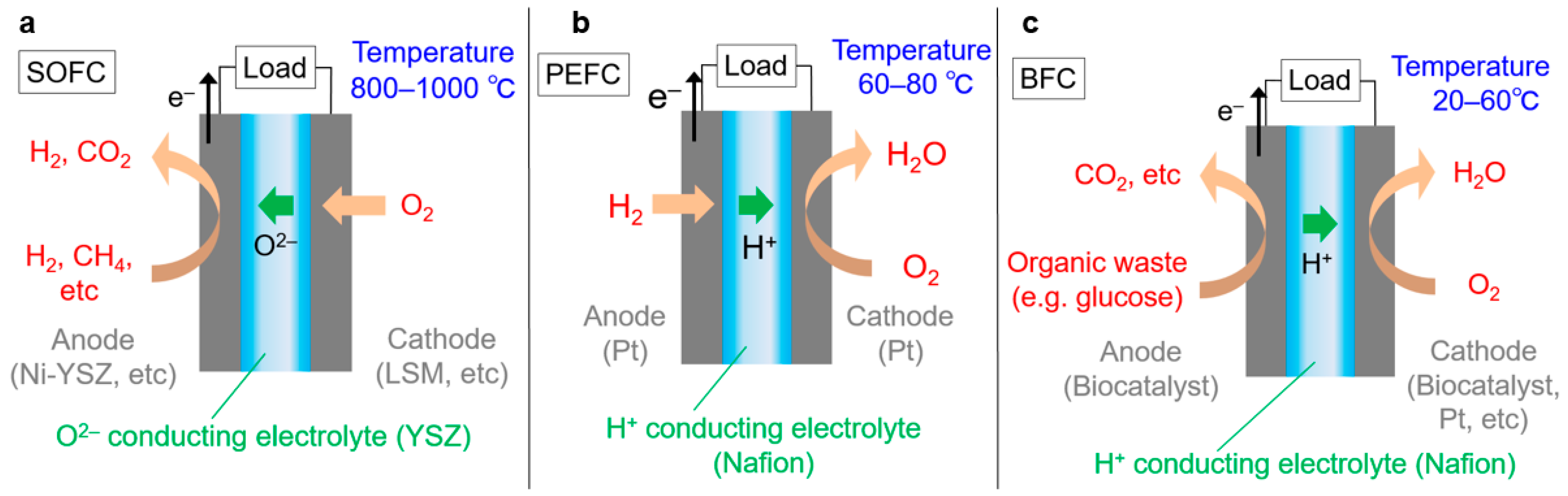
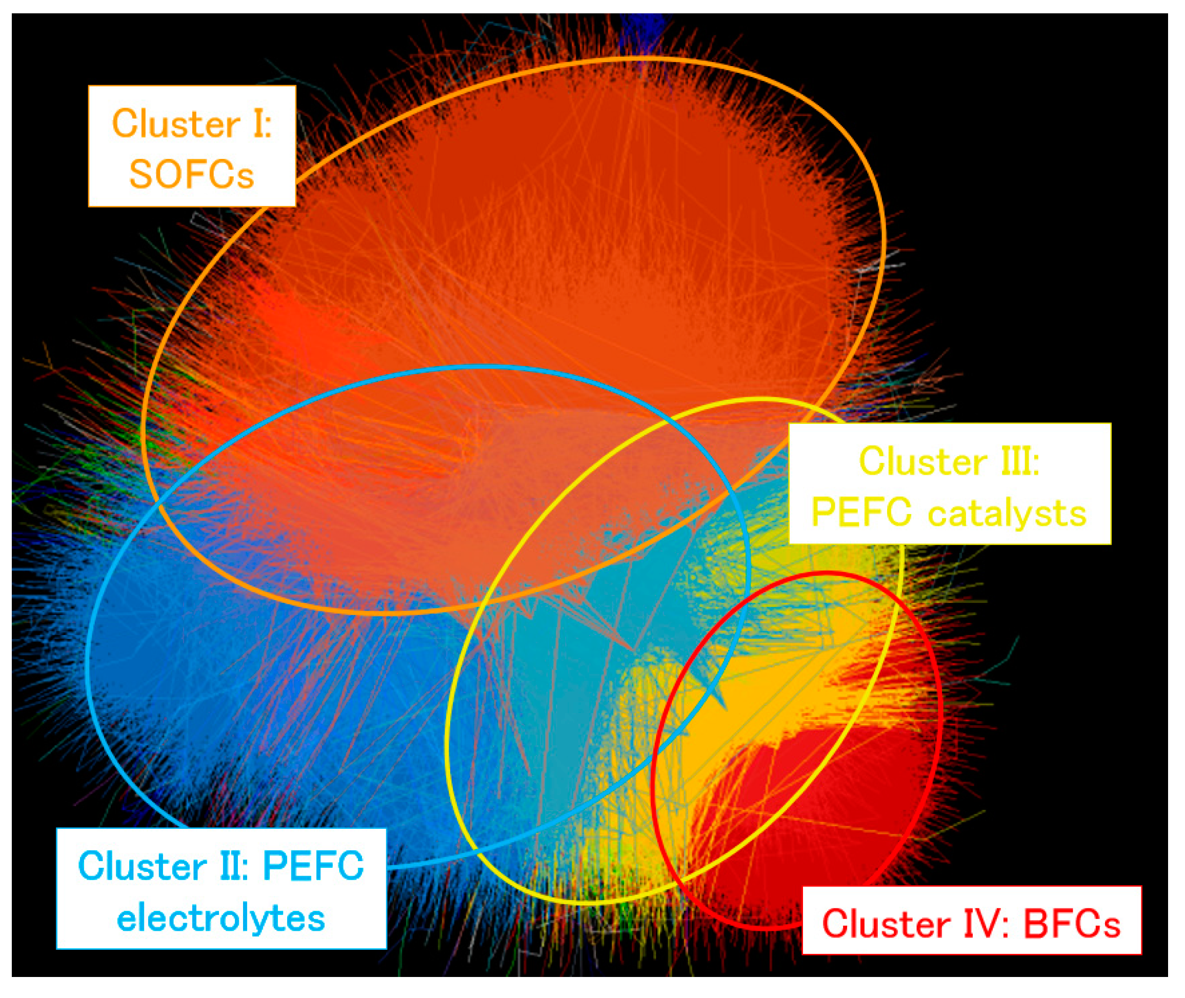
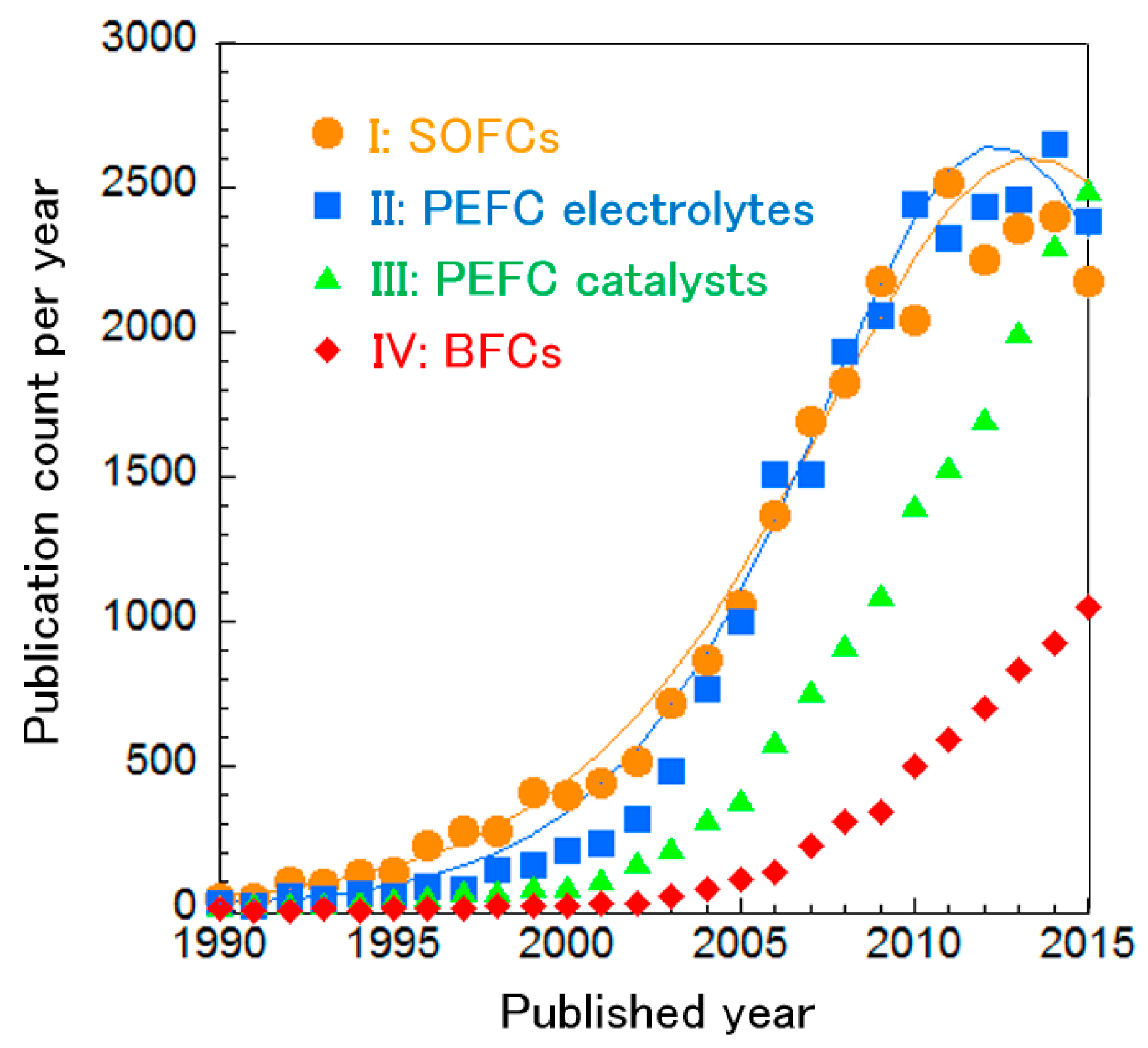
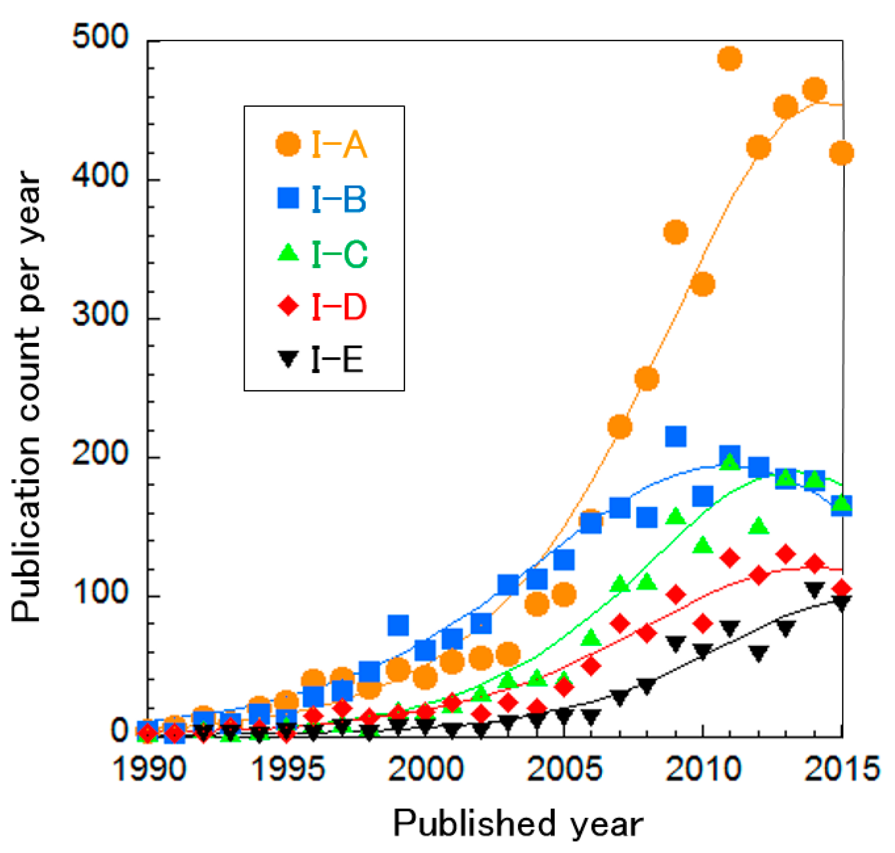
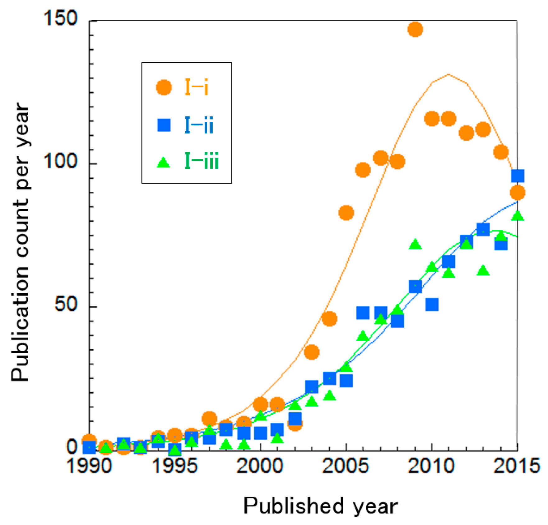
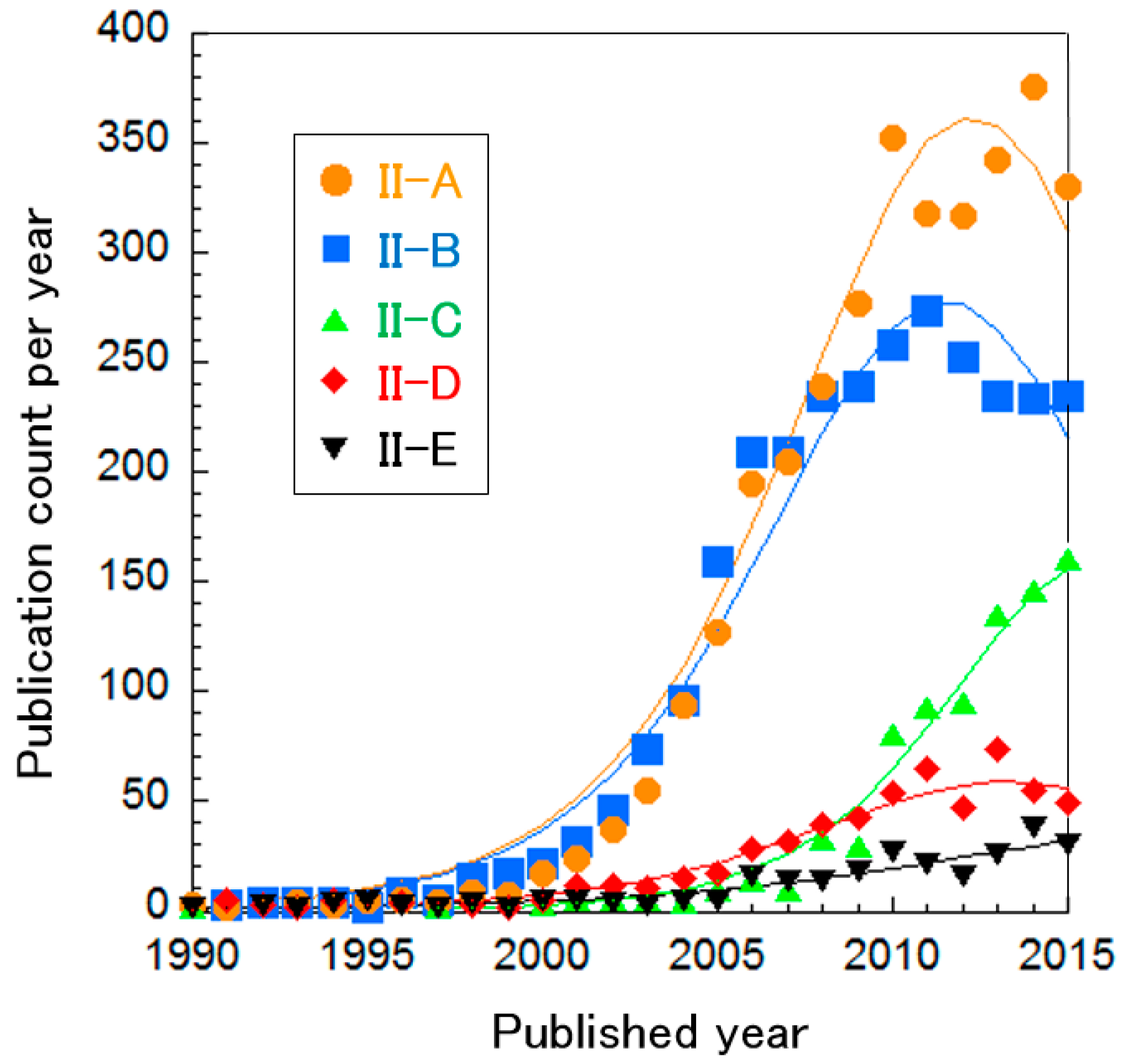
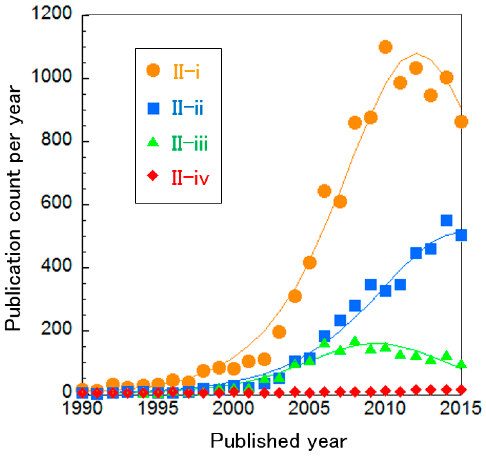
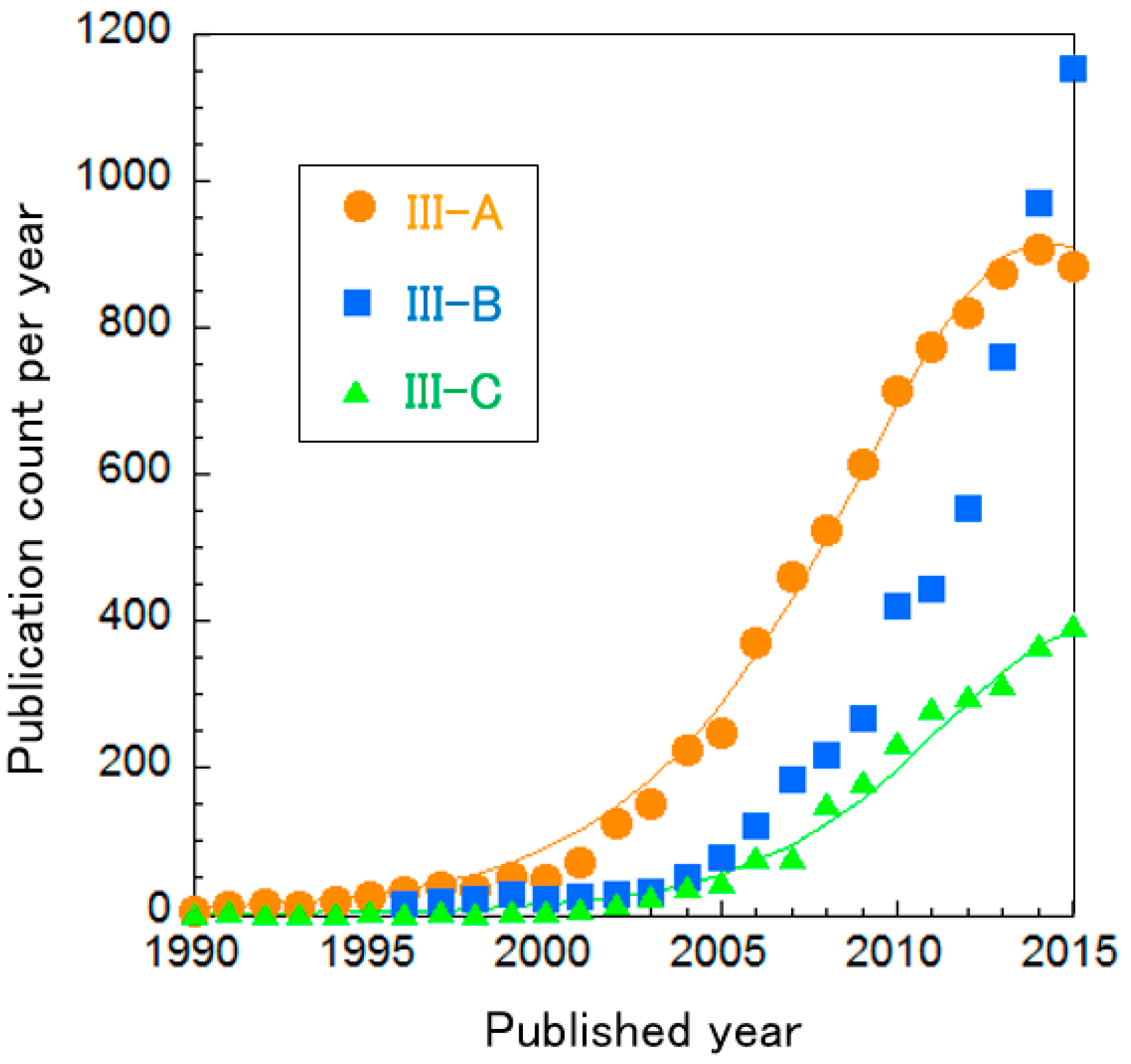
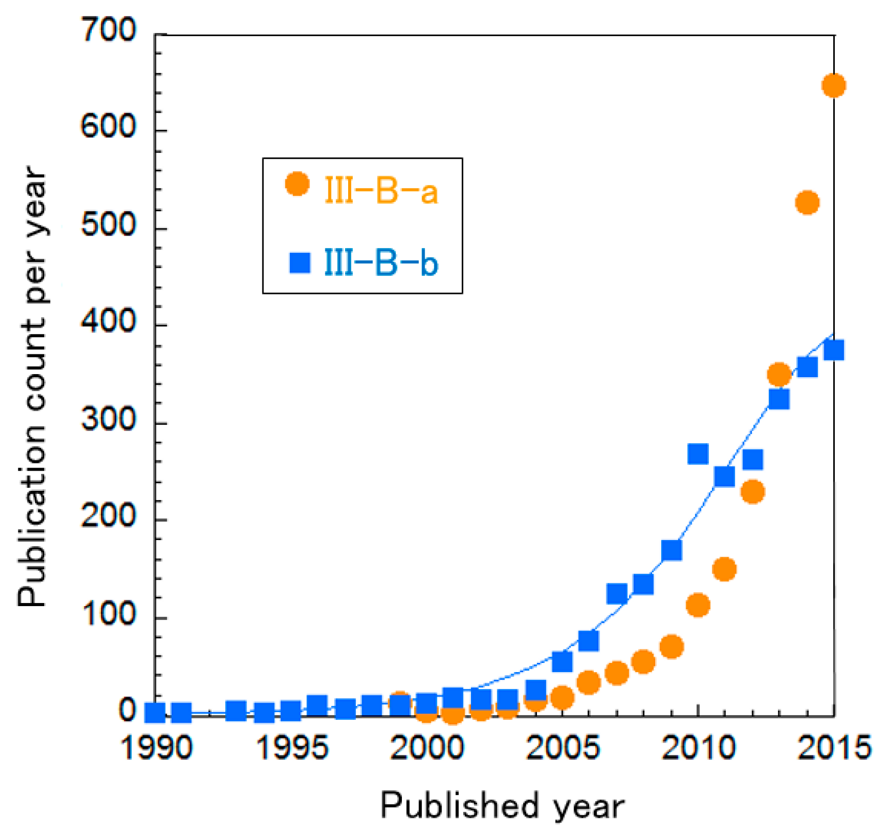
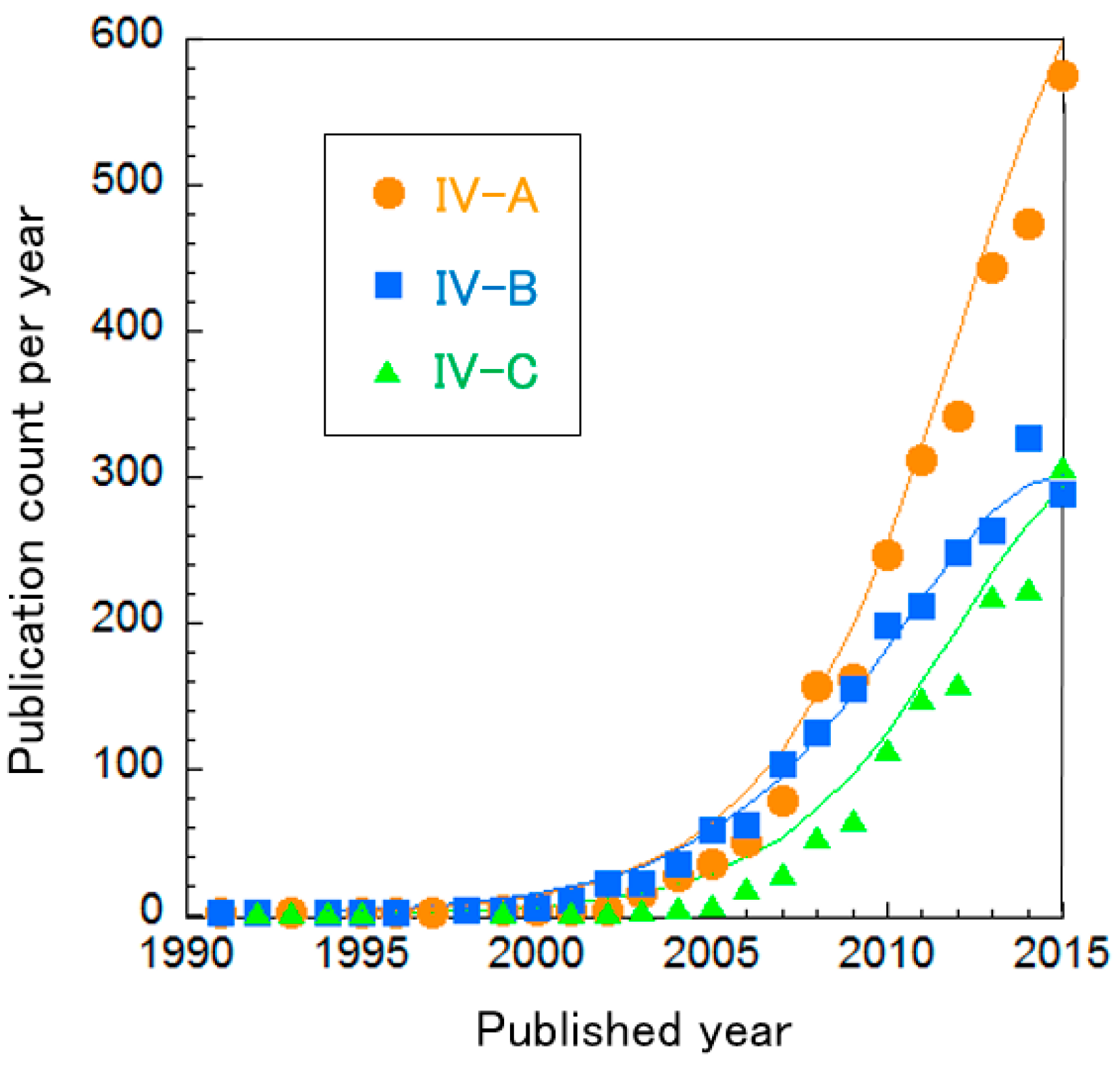
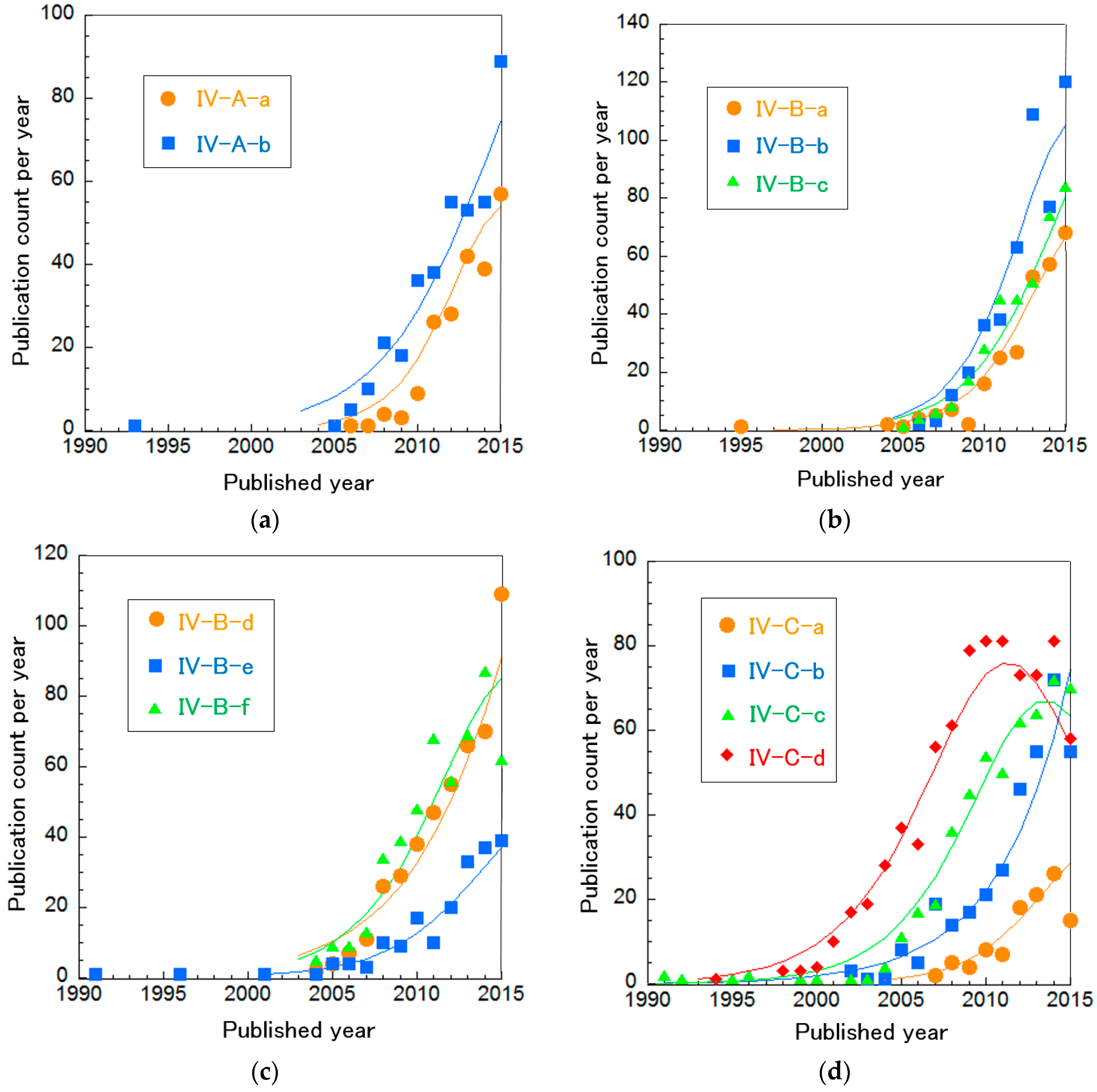
Table 1.
Detailed information of each fuel cell type.
| SOFCs | PEFCs | BFCs | ||
|---|---|---|---|---|
| PEFC Electrolytes | PEFC Catalysts | |||
| Publication count | 28,233 | 27,019 | 18,418 | 7507 |
| Average publication year | 2009.0 | 2009.9 | 2010.8 | 2012.4 |
| Operation conditions | 800–1000 °C | 60–80 °C | MFC: 20–60 °C EBFC: 20–40 °C | |
| Conducting ion | O2− (or H+) | H+ (or OH−) | H+ | |
| Energy efficiency [19] | 55–65% (85% with cogeneration) | 40–60% | MFC: 15–65% EBFC: 30% | |
| Advantages | No requirement of precious metal for catalysts, small number of components (low cost), high energy efficiency, high exergy of waste heat | Quick start and stop, moderate operation condition, small size | Broad fuel selection, moderate operation temperature (around human body temperature), no requirement of precious metals for catalysts, small size | |
| Disadvantages | Slow start and stop, high cost for interconnection materials | High cost of platinum for catalysts, low ion conductivity of electrolytes at low humidity condition, requirement of highly purified hydrogen gas | Low durability, low current density | |
| Application | Distributed energy generator | Portable power source (automobile, laptop, etc.) | Purification of wastewater with power production, intravital energy source (a cardiac pacemaker, etc.) | |
Table 2.
Main clusters in SOFC technologies.
| Cluster | Research Topic | Publication Count | Average Publication Year |
|---|---|---|---|
| I-A | Oxygen reduction on cathode | 4541 | 2010.1 |
| I-B | Oxide ion conducting oxide | 2705 | 2007.9 |
| I-C | Anode tolerance | 1842 | 2010.1 |
| I-D | Fuel Oxidation on anode | 1270 | 2009.6 |
| I-E | Proton conducting oxide | 744 | 2011.2 |
Table 3.
Topics about the overall SOFC system.
| Cluster | Research Topic | Publication Count | Average Publication Year |
|---|---|---|---|
| I-i | Three-dimensional numerical simulation of SOFC stacks | 1423 | 2009.2 |
| I-ii | Micro combined heat and power | 817 | 2010.1 |
| I-iii | SOFCs with gas turbines | 784 | 2009.8 |
Table 4.
Emerging SOFC technologies.
| Cluster | Research Topic | Publication Count | Average Publication Year |
|---|---|---|---|
| I-1 | MBaCo2O5+δ (M = Gd, Pr, Nd, Sm) for IT-SOFC cathodes | 442 | 2012.1 |
| I-2 | BaxSr1−xCo0.8Fe0.2O3−δ (BSCF) for IT-SOFC cathodes | 405 | 2012.7 |
| I-3 | YBaCo3ZnO7 catalyst and GDC for IT-SOFC cathodes | 37 | 2012.4 |
| I-4 | Theoretical research on LaMO3 (M = Mn, Fe, Co and Ni) cathodes | 235 | 2013.0 |
| I-5 | Symmetrical SOFCs | 204 | 2012.6 |
| I-6 | Diagnostic methodology and degradation techniques | 47 | 2012.4 |
| I-7 | Sr2MgMoO6−δ anode tolerance from S poisoning | 118 | 2012.2 |
| I-8 | Yttrium-doped BaZrO3 | 209 | 2012.0 |
| I-9 | Calcium-doped LaNbO4 | 88 | 2011.7 |
Table 5.
Main clusters of PEFC membrane research.
| Cluster | Research Topic | Publication Count | Average Publication Year |
|---|---|---|---|
| II-A | Organic/inorganic composites | 4851 | 2009.2 |
| II-B | Sulfonated hydrocarbon polymers | 3547 | 2010.4 |
| II-C | SAFCs | 950 | 2012.6 |
| II-D | Nano-structure of Nafion | 597 | 2009.8 |
| II-E | Phosphoric acid-doped PBI membranes | 282 | 2009.5 |
Table 6.
The overall PEFC system.
| Cluster | Research Topic | Publication Count | Average Publication Year |
|---|---|---|---|
| II-i | Modeling mass transport in PEFCs | 11,084 | 2009.7 |
| II-ii | Bipolar plates/optimization of components in PEFCs | 4357 | 2010.7 |
| II-iii | Micro-DMFCs | 1794 | 2008.5 |
| II-iv | AFCs | 171 | 2005.9 |
Table 7.
Emerging PEFC electrolyte technologies and research related to PEFC applications.
| Cluster | Research Topic | Publication Count | Average Publication Year |
|---|---|---|---|
| II-1 | Fuel cell vehicles | 768 | 2011.9 |
| II-2 | Anion exchange membrane for SAFCs | 488 | 2013.7 |
| II-3 | Nano-organic/inorganic composite using graphene oxides and CNTs | 254 | 2012.9 |
| II-4 | Cost analysis of hybrid system combining sustainable energy and PEFCs | 52 | 2013.5 |
| II-5 | Tomography of catalyst layers | 42 | 2013 |
Table 8.
Main clusters of PEFC catalysts.
| Cluster | Research Topic | Publication Count | Average Publication Year |
|---|---|---|---|
| III-A | Alcohol (typically methanol) oxidation on anodes | 8668 | 2010.0 |
| III-B | Oxygen reduction on cathodes | 6365 | 2012.1 |
| III-C | Other fuel oxidation besides alcohol on anodes | 2795 | 2011.2 |
Table 9.
Research topics regarding PEFC cathodes.
| Cluster | Research Topic | Publication Count | Average Publication Year |
|---|---|---|---|
| III-B-a | N-doped graphene/CNT and non-precious metals (typically Co and Fe) | 2859 | 2013.0 |
| III-B-b | Pt-based alloys | 2823 | 2011.4 |
Table 10.
Emerging PEFC catalyst technologies.
| Cluster | Research Topic | Publication Count | Average Publication Year |
|---|---|---|---|
| III-1 | Nanostructure of Pt-based bimetallic catalysts | 1112 | 2013.1 |
| III-2 | Pt on graphene for methanol oxidation | 581 | 2013.2 |
| III-3 | Pd-based catalyst for electrooxidation of alcohol in alkali media | 371 | 2013.0 |
| III-4 | Fe- or Co-based catalysts on N-doped graphene/CNT | 592 | 2014.6 |
| III-5 | N-Doped graphene/CNT for cathodes | 379 | 2012.8 |
| III-6 | Other heteroatom-doped graphene/CNT for cathodes | 372 | 2014.2 |
| III-7 | Preparation of N-doped C from ionic liquids or biomass | 149 | 2013.8 |
Table 11.
Main BFC clusters.
| Cluster | Research Topic | Publication Count | Average Publication Year |
|---|---|---|---|
| IV-A | DET in anodes for MFCs | 1656 | 2012.8 |
| IV-B | Overall system and each component of MFCs | 3554 | 2012.6 |
| IV-C | EBFCs | 2459 | 2011.3 |
Table 12.
Research topics related to BFCs.
| Cluster | Research Topic | Publication Count | Average Publication Year |
|---|---|---|---|
| IV-A-a | Nanostructured C-supported anodes for MFCs | 275 | 2013.7 |
| IV-A-b | Electron transfer mechanisms in Shewanella and Geobacter | 448 | 2012.8 |
| IV-B-a | Optimizing MFC performance | 353 | 2013.5 |
| IV-B-b | Bioremediation using MFCs | 596 | 2013.4 |
| IV-B-c | Non-Pt cathodes for MFCs | 471 | 2013.4 |
| IV-B-d | Cell stack engineering for scale-up | 572 | 2012.9 |
| IV-B-e | Electricity production from sediment and sulfide in seawater | 227 | 2012.6 |
| IV-B-f | Electricity production during wastewater treatment | 591 | 2012.3 |
| IV-C-a | Practical demonstration in vivo | 250 | 2013.7 |
| IV-C-b | Enzymatic bioelectrocatalyst for EBFCs | 413 | 2012.6 |
| IV-C-c | High current density and long durability of EBFCs | 585 | 2011.7 |
| IV-C-d | EBFCs with mediators or redox polymers | 842 | 2009.7 |
Table 13.
Emerging BFC technologies.
| Cluster | Research Topic | Publication Number | Average Publication Year |
|---|---|---|---|
| IV-1 | MBRs integrated with MFCs for wastewater treatment | 73 | 2014.2 |
| IV-2 | N-doped nanostructured carbons as cathode in MFCs | 62 | 2014.6 |
| IV-3 | EBFCs for contact lenses | 59 | 2014.7 |
| IV-4 | FAD-dependent GDHs for EBFCs | 43 | 2014.3 |
| IV-5 | Paper-based MFCs | 38 | 2014.2 |
© 2018 by the authors. Licensee MDPI, Basel, Switzerland. This article is an open access article distributed under the terms and conditions of the Creative Commons Attribution (CC BY) license (http://creativecommons.org/licenses/by/4.0/).
Share and Cite
MDPI and ACS Style
Ogawa, T.; Takeuchi, M.; Kajikawa, Y. Comprehensive Analysis of Trends and Emerging Technologies in All Types of Fuel Cells Based on a Computational Method. Sustainability 2018, 10, 458. https://doi.org/10.3390/su10020458
AMA Style
Ogawa T, Takeuchi M, Kajikawa Y. Comprehensive Analysis of Trends and Emerging Technologies in All Types of Fuel Cells Based on a Computational Method. Sustainability. 2018; 10(2):458. https://doi.org/10.3390/su10020458
Chicago/Turabian StyleOgawa, Takaya, Mizutomo Takeuchi, and Yuya Kajikawa. 2018. "Comprehensive Analysis of Trends and Emerging Technologies in All Types of Fuel Cells Based on a Computational Method" Sustainability 10, no. 2: 458. https://doi.org/10.3390/su10020458
Note that from the first issue of 2016, this journal uses article numbers instead of page numbers. See further details here.