
Simultaneous Measurement of Microdisplacement and Temperature Based on Balloon-Shaped Structure
by
 , ,
, ,
Yaxun Zhang
1,2,3,
Yuxin Liu
1,2,3,
Zhiliang Huang
1,2,3,
Pingbang Huang
1,2,3,
Xiaoyun Tang
1,2,3,4,*,
Zhihai Liu
2,3,
Yu Zhang
2,3 and
Libo Yuan
2,5 1
Qingdao Innovation and Development Center, Harbin Engineering University, Qingdao 266500, China
2
Key Lab of In-Fiber Integrated Optics, Ministry Education of China, Harbin Engineering University, Harbin 150001, China
3
Key Laboratory of Photonic Materials and Device Physics for Oceanic Applications, Ministry of Industry and Information Technology of China, Harbin Engineering University, Harbin 150001, China
4
College of Shipbuilding Engineering, Harbin Engineering University, Harbin 150001, China
5
College of Photonic and Electronic Engineering, Guilin University of Electronic Technology, Guilin 541004, China
*
Author to whom correspondence should be addressed.
Sensors 2023, 23(20), 8521; https://doi.org/10.3390/s23208521
Submission received: 27 August 2023
/
Revised: 19 September 2023
/
Accepted: 21 September 2023
/
Published: 17 October 2023
(This article belongs to the Special Issue Recent Advances in Micro- and Nanofiber-Optic Sensors)
Abstract
:An optical fiber sensor for the simultaneous measurement of microdisplacement and temperature based on balloon-shaped single-mode fibers cascaded with a fiber Bragg grating with two core-offset joints is proposed. The interference between the core mode and cladding mode is caused by the stimulation of the cladding mode by the core-offset joints’ structure. The cladding of the core has a distinct refractive index, which causes optical path differences and interference. The balloon-shaped structure realizes mode selection by bending. As the displacement increases, the radius of the balloon-shaped interferometer changes, resulting in a change in the interference fringes of the interferometer, while the Bragg wavelength of the fiber grating remains unchanged. Temperature changes will cause the interference fringes of the interferometer and the Bragg wavelength of the fiber grating to shift. The proposed optical fiber sensor allows for the simultaneous measurement of microdisplacement and temperature. The results of the experiment indicate that the sensitivity of the interferometer to microdisplacement is 0.306 nm/µm in the sensing range of 0 to 200 μm and that the temperature sensitivity is 0.165 nm/°C, respectively. The proposed curvature sensor has the advantages of a compact structure, extensive spectrum of dynamic measurement, high sensitivity, and simple preparation, and has a wide range of potential applications in the fields of structural safety monitoring, aviation industry, and resource exploration.
1. Introduction
Microdisplacement sensors have a high level of measurement precision, such as conventional interferometers, eddy current sensors, and optical fiber sensors, amongst others [1,2]. However, interferometers [3] are difficult to implement due to their size and complexity. Eddy current sensors [4] are susceptible to electromagnetic interference and possess a low degree of precision. Compared with the conventional microdisplacement sensor, the optical fiber sensor has the advantages of a high integration and good anti-interference performance. Fiber-based microdisplacement sensors typically use grating structures, including fiber Bragg gratings (FBG) [5,6,7], long-period fiber gratings (LPFG) [8], and tilted gratings [9]. In addition, there are optical-fiber microdisplacement sensors based on different interference principles, including multimode interference (MMI) [10], Mach–Zehnder interference (MZI) [11], Fabry–Perot interference (FPI) [12,13,14], etc. In comparison to grating microdisplacement sensors, optical fiber sensors based on the interference principle offer a greater measurement precision and wider measurement range.
In order to increase the sensitivity of optical fiber sensors, various configurations of optical fiber sensors with offset core structures have been proposed [15,16]. The structure is spliced by the offset axis of the fiber core and the cladding, causing interference between the cladding mode and the core mode. By utilizing a single-mode fiber with an offset core, Wen et al. [17] measured the refractive index with a high sensitivity. However, the mechanical properties of the sensor are insufficient due to the large offset of the offset core. Qiu et al. [18] manufactured refractive index (RI) sensors by clamping the hollow fiber (HCF) section between the tail fiber introduced into the single-mode fiber (SMF) and the reflected SMF section to enhance the device’s mechanical properties. Similar structures were used by Huang et al. [19] to simultaneously measure strain and temperature. The structure of the sensor is compact, and the length of the device can be further reduced. Zhang [20] improved the Mach–Zehnder interference, accomplished torsion sensing, and decreased the cross sensitivity between torsion and temperature by employing the offset core construction. Gu et al. [21] addressed the core shift sensor for biomolecule detection based on SMF and multimode fiber. The findings demonstrate the significant potential of the core offset structure in the creation of optical fiber sensors for biological detection. The optical fiber’s bending structure can also increase the sensitivity of the optical fiber sensor [22]. This method is extensively used to measure physical parameters, such as the refractive index [23,24,25], magnetic field [26], curvature [27], temperature [28], and salinity [29]. Combining the dislocation and bending structure of an optical fiber was previously difficult to achieve in the previous way. To achieve mode selection, we bring bending into dislocation. The decoupling method of the dual-parameter measurement of the optical fiber sensor can be decoupled by the machine-learning method in addition to the sensitivity transfer matrix [30]. The difference between the two is that the transfer matrix method theoretically obtains an accurate solution, while machine learning requires a lot of learning [31,32,33].
In this article, we present a fiber sensor for the simultaneous measurement of microdisplacement and temperature, which is composed of core-offset-joints (COJs)-based balloon-shaped SMF and FBG with two. The COJs are realized by splicing three single-mode fibers with a minor lateral offset. Due to this design offset, the interference will occur between the core mode and the cladding mode. A balloon-shaped structure is used to select the interference mode and form the Mach–Zehnder interference. The FBG cascaded with spherical SMF with COJs can sense temperature changes. The spectral pattern of the device will change when the displacement and/or temperature of the ambient material vary. The theoretical analysis is consistent with the experimental results. The results indicated that this novel sensor has the advantage of a simple configuration, low cost, easy operation, high sensitivity and stability.
2. Theory and Sensing Principle
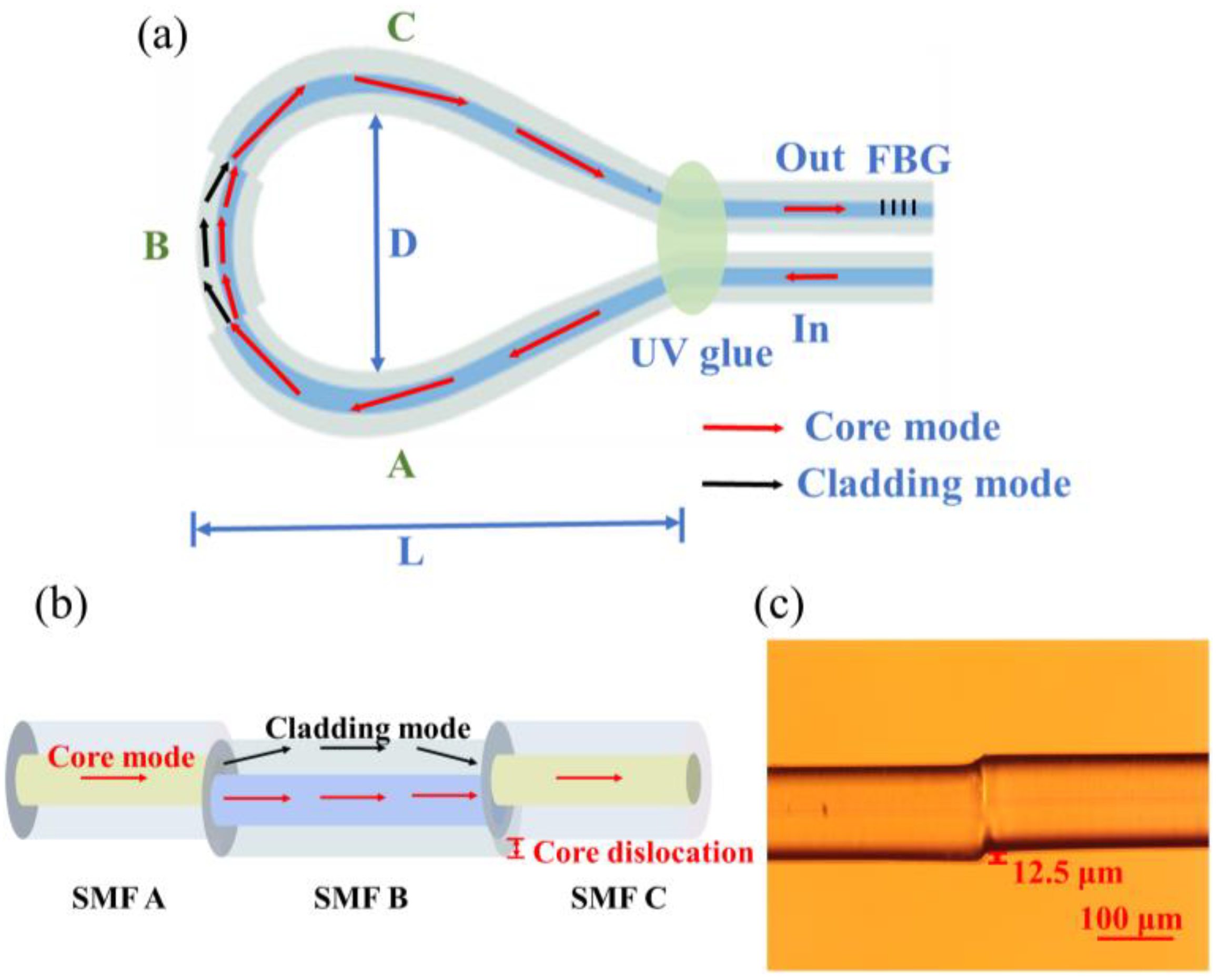
Figure 1a shows a schematic diagram of the balloon-shaped core-offset bending SMF fiber structure. The values D and L represent the bending diameter and breadth of the structure, respectively. The SMF structure with a core offset is centered on top of the balloon structure.
As seen in Figure 1a, we realize partial cladding mode excitation by cascading bending. Due to the COJ structure in Figure 1b, the light is separated into two pathways: one enters the core of the SMF B, and the other is sent into the cladding as a cladding mode. After propagating for a distance in the SMF B, the light in the cladding enters the multimode SMF C and can be coupled back to the core. Two fiber core-offset structures generate MZI interference owing to the phase mismatch between the cladding mode and the core mode. The transfer function of MZI is expressed as:
where I is the intensity of the interference signal. I1 and I2 are the intensities of the core and cladding modes. Δn is the effective refractive index difference between the core mode n1 and the cladding mode n2. d is the interferometer arm length, whereas λ is the operational wavelength. Therefore, the reduction in transmission spectrum wavelength λk may be stated as:
The interval between consecutive peaks is approximately λ2/Δnd. Multimode interference makes up the majority of fiber MZI. In this structure, the cladding of the SMF can be regarded as a multimode waveguide. Due to the core-offset splicing approach, a beam from a portion of the core spreads to the cladding, generating an MZI with more than one mode. Since each mode responds differently to changes in the environment, this multimode interference affects the sensing performance. In order to control the generated cladding mode, we achieve mode selection by bending part of the core-offset connection. The bent offset core structure will cause n to alter, which will cause k to vary as well. We use spectral drift to calculate the microdisplacement. The RI distribution in the COJ-based balloon-shaped SMF structure can be expressed as [22]:
where x is the normal axis of the bending fiber, n0 is the RI of the straight fiber section, and reff is the equivalent bending radius, which may be computed by [24]:
where r is the actual bending radius of the fiber, and ν is the ratio of Poisson. P11 and P12 are the photoelastic tension of each component. The bending causes the refractive index to shift. In general, RI decreases to the outside of the bending.
The characteristic of FBG is that the RI of the optical fiber core can be periodically modulated. The temperature response of FBG is mainly affected by the thermal dependence of RI [33]. Therefore, FBG can resonate with the Bragg wavelength λFBG, which is determined by the effective RI of the fiber core neff and the grating period Λ. The λFBG can be expressed as [7]:
Based on the foregoing theoretical study, (2) demonstrates that, in principle, the longer the SMF B, the better. However, in the experiment, the mechanical strength of the sensor will be diminished due to the excessive length of the SMF B. After calculation and experimental verification, the 25-mm-length sensor can demonstrate a satisfactory performance. The core/cladding diameter and RI of SMF are 8.2/125 μm and 1.4446/1.4447, respectively. The amount of core dislocation z is 12.5 μm.
3. Experimental Results
3.1. Experimental Setup
To fabricate the balloon-shaped core-offset bending SMF fiber structure shown in Figure 1, two core-offset structures were fabricated on SMF (Corning SMF-28, New York, NY, USA) using a commercial fiber fusion splicer (Fujikura-88S, Tokyo, Japan). The direction between the two COJ-based structures are irrelevant, which simplifies the production process. The two COJ-based structures have an offset of around 12.5 μm. Figure 1c depicts the microscopic view of a single offset core structure. The bending radius R of the fabricated sample is 12.83 mm to obtain the best interference deflection extinction ratio, and the corresponding width of the balloon-shaped section L is 65.92 mm. FBG is connected in series with the fiber structure.
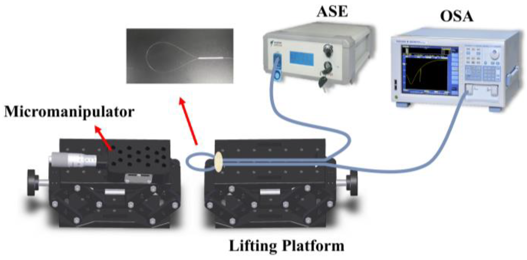
The displacement measurement experimental setup is depicted in Figure 2. The height of the lifting platform is adjustable, and ultraviolet (UV) glue is used to adhere the sample to the platform. The micromanipulator (MPC-385, Sutter, Atlanta, GA, USA) is utilized to manually modify the translation stage’s position. The accuracy of the displacement adjustment is 1 µm, which adjusted the axial displacement and applied it to the balloon-shaped section precisely. In order to describe the device, a broadband light source (ASE, Hoyatek, Shenzhen, China) is emitted into it, and an optical spectrum analyzer (OSA, AQ6370D, Yokogawa, Tokyo, Japan) with a maximum spectral resolution of 0.02 nm is utilized to monitor the transmission spectrum.
3.2. Results and Discussion
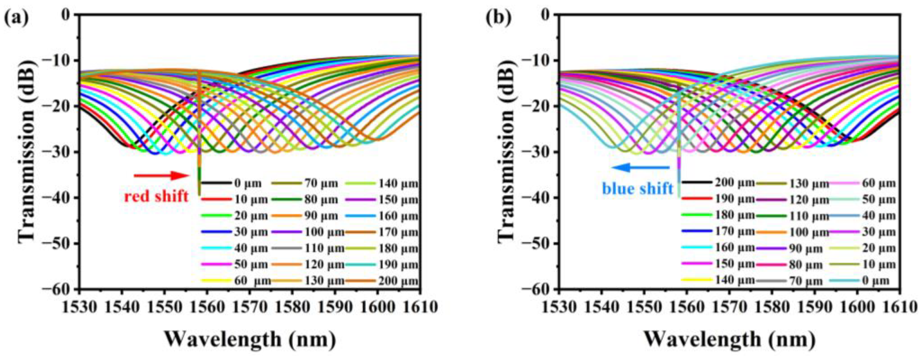
As depicted in Figure 3a, there is a desired interference dip angle between 1530 and 1610 nm. There are two reasonably significant extinction ratio dips in the recorded spectrum for the later measurement: the resonance wavelength induced by FBG at 1558.16 nm (dip B) and the resonance wavelength of MZI at 1540.14 nm (dip A).
The transmission spectrum of the fiber structure varies when the displacement is between 0–200 μm and the step size is 10 μm. In order to evaluate the repeatability of the sample sensor, the displacement is decreased from 200 μm to 0 μm and the measurement process is performed in reverse. The results are displayed in Figure 3b. As depicted in Figure 3a, when the displacement increases, the inclination angle at 1540.14 nm is red-shifted, while the inclination extinction ratio remains nearly unchanged. As depicted in Figure 3b, the spectral evolution is reversed when the displacement direction changes. Due to the peculiarity of the Bragg grating resonance wavelength, when the displacement varies, the wavelength of dip B remains unchanged at 1558.14 nm. The variation in the dip A wavelength is due to the form change of the balloon-shaped cross section produced by displacement, which ultimately results in the variation of the effective bending length reff and the variation of optical coupling between the SMF core and cladding. During the experiment, the inclination extinction ratio will fluctuate slightly due to shifts in temperature, humidity, etc.
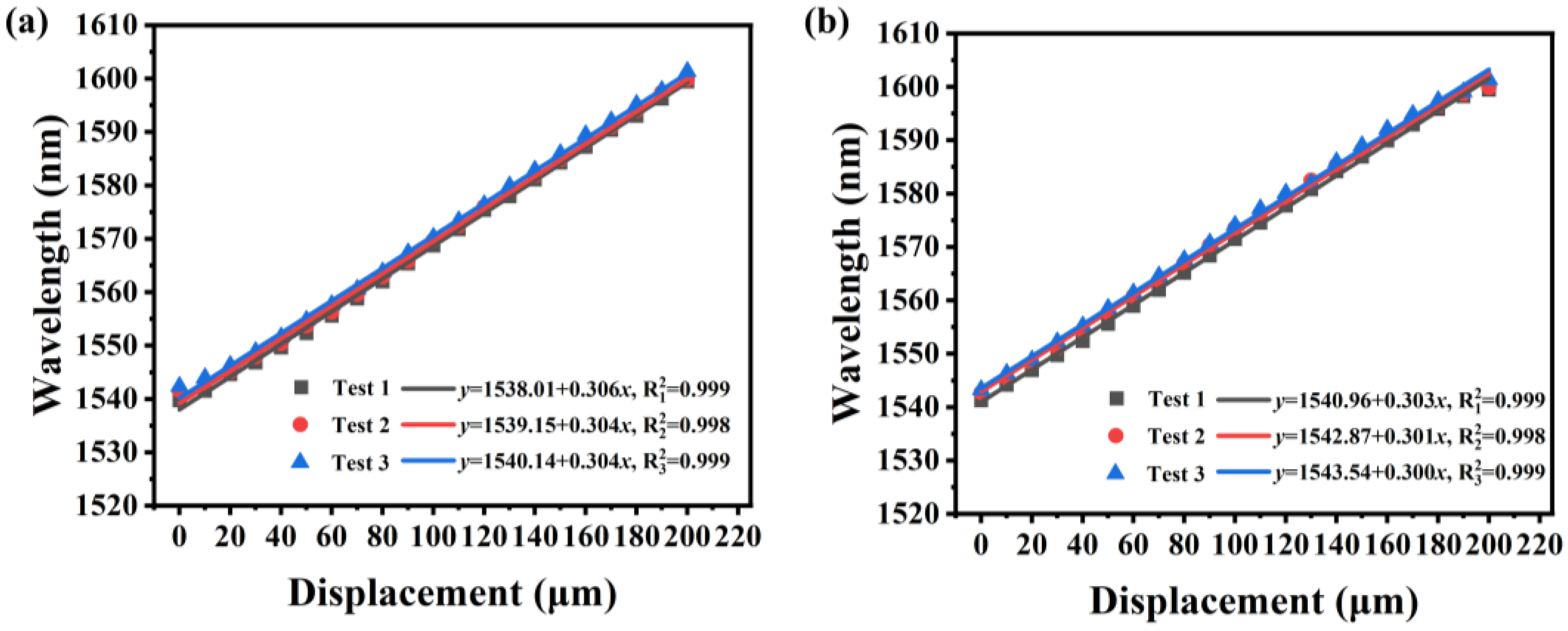
The wavelength shift and intensity change of dip A with increasing and decreasing displacement are linearly fitted in Figure 4a,b, respectively. The wavelength-displacement sensitivity of dip A to the displacement-increasing process may be computed from Figure 4a as reaching 0.306 nm/μm, and the linear regression coefficient (R2) achieves 0.999. The sensitivity of dip A to the displacement-reduction procedure can approach 0.303 nm/μm, and R2 is 0.999, as can be seen in Figure 4b. This sample also demonstrates that there is almost no hysteresis in the sensor and that the displacement measurement has good repeatability: the outcomes of three separate experiments are virtually identical.
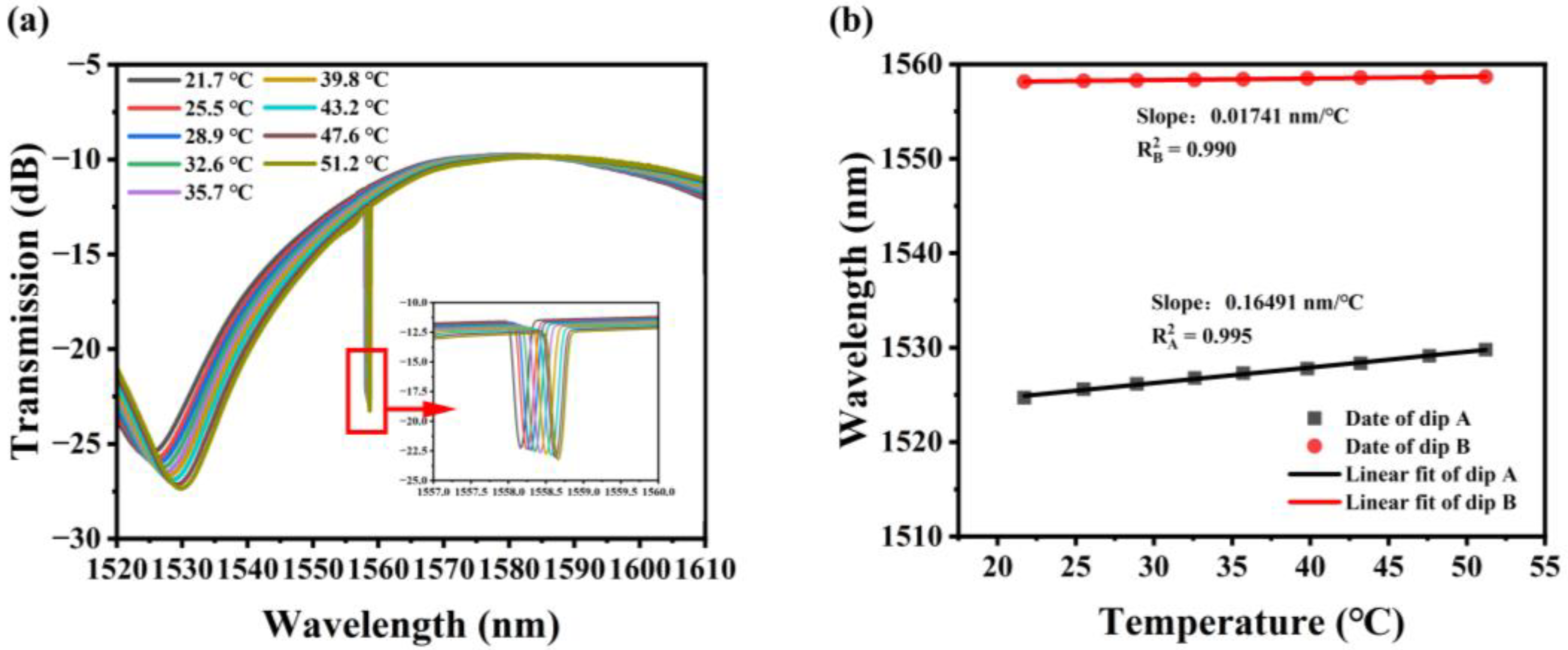
In addition to measuring displacement, the temperature dependence of the pro-posed fiber structure was investigated by placing the sensor sample on a heating plat-form. The temperature measurement range is 21.7–51.2 °C due to the limited operating temperature range of the UV glue. The transmission spectrum of the sensor changes when the temperature changes, as shown in Figure 5a. Redshift happens as dips A and B both drift to longer wavelengths as the temperature rises. Figure 5b depicts the displayed and fitted measured data. According to the findings of the linear fitting, dip A generated by MZI has a temperature sensitivity of 0.165 nm/°C, and dip B induced by FBG has a temperature sensitivity of 0.017 nm/°C, with R2 values of 0.995 and 0.990, respectively. It is worth noting that dip A in this structure has a temperature sensitivity that is 9.47 times greater than dip B, indicating that the MZI interference caused by the curved offset core structure is temperature-sensitive.
The wavelength shift of the dip A transmission spectrum is composed of temperature change and displacement change. Based on the experimental findings described above, the displacement and temperature changes of the sensor can be described by the following matrix:
The wavelength changes of the offset-core bent MZI and FBG are represented by ∆λdipA and ∆λdipB, respectively. The displacement sensitivity and temperature sensitivity of MZI are denoted by and . The temperature sensitivity of FBG is . The changes in temperature and displacement are denoted by Δx and ΔT. The variation of temperature and displacement can be expressed using the below matrix:
Additionally, considering that the OSA utilized in the experiment has a resolution of 0.02 nm, the sensor system’s displacement measurement resolution is 1 μm, and the temperature measurement precision is 0.1 °C, all of which are acceptable for usage in actual applications.
The proposed sensor is compared to displacement and temperature sensors with various optical setups that have been previously described. The sensors using wavelength demodulation have a high sensitivity and large measuring range, as shown in Table 1. According to Table 1, our sensor has a higher sensitivity than those from earlier research. The sensitivity of our sensor is much higher than that of the same type of temperature and displacement dual-parameter measurement sensor with a balloon shape. Our work’s displacement sensitivity is 182.14 times higher than its displacement sensitivity and 5.77 times higher than its sensitivity to temperature [22]. In addition, the sensor benefits from an easy construction, high reproducibility, and excellent stability. The optical fiber sensor has great application potential in the field of optical fiber sensing, since it can simultaneously monitor displacement and temperature.
4. Conclusions
In this article, we propose and investigate a COJ-based balloon-shaped structure cascaded with an FBG-based simultaneous microdisplacement-and-temperature-measurement optical fiber sensor. The interference between the core mode and cladding mode is caused by the stimulation of the cladding mode by the core-offset joints’ structure. The balloon-shaped structure realizes mode selection by bending. Temperature changes will cause the interference fringes of the interferometer and the Bragg wavelength of the fiber grating to shift. The results indicate that the displacement sensitivity of the sensor is 0.306 nm/μm and that its measuring range is 0–200 μm. The temperature sensitivity in the range of 21.7–51.2 °C is 0.165 nm/°C. The suggested sensor further benefits from easy manufacturing, high reliability, low cost, and good repeatability.
Author Contributions
Conceptualization, Y.L. and Z.H.; methodology, Y.L. and Z.H.; validation, Y.Z. (Yaxun Zhang), P.H. and X.T.; resources, Y.Z. (Yaxun Zhang); writing—original draft preparation, Y.L.; writing—review and editing, X.T.; supervision, Y.Z. (Yu Zhang); funding acquisition, Y.Z. (Yu Zhang), X.T., Y.Z. (Yaxun Zhang), Z.L. and L.Y. All authors have read and agreed to the published version of the manuscript.
Funding
This research is supported by the National Natural Science Foundation of China (62205086, 62175046, 61975039); China Postdoctoral Science Foundation (2022M720940); Heilongjiang Provincial Natural Science Foundation of China (YQ2020F011); Postdoctoral Foundation of Heilongjiang Province of China (LBH-Z21128); Postdoctoral Innovation Project of Shandong Province (SDCX-ZG-202203017); Postdoctoral Applied Research Project of Qingdao; 111 Project (B13015) and Fundamental Research Funds of Harbin Engineering University.
Institutional Review Board Statement
Not applicable.
Informed Consent Statement
Not applicable.
Data Availability Statement
Not applicable.
Conflicts of Interest
The authors declare no conflict of interest.
References
- Wei, Y.; Shi, C.; Liu, C.; Liu, C.; Jiang, T.; Wang, R.; Hu, L.; Zhang, Y. Fiber SPR Two-Dimensional Micro Displacement Sensor Based on the Coaxial Double Waveguide with a Conical Structure. Opt. Express 2022, 30, 24909–24923. [Google Scholar] [CrossRef] [PubMed]
- Luo, H.; Yu, J.; Wang, J.; Ma, C.; Han, X.; Su, X. High-Precision Micro-Displacement Sensing Based on an Optical Filter and Optoelectronic Oscillators. Opt. Express 2023, 31, 19278–19292. [Google Scholar] [CrossRef] [PubMed]
- Guo, D.; Shi, L.; Yu, Y.; Xia, W.; Wang, M. Micro-Displacement Reconstruction Using a Laser Self-Mixing Grating Interferometer with Multiple-Diffraction. Opt. Express 2017, 25, 31394–31406. [Google Scholar] [CrossRef] [PubMed]
- Mizukami, K.; Hioki, S.; Takahashi, Y.; Ogi, K. Experimental and Numerical Analysis of Eddy Current Sensor Signal Induced by Out-of-Plane Fiber Waviness in Carbon Fiber Composites. Compos. Part A Appl. Sci. Manuf. 2022, 163, 107173. [Google Scholar] [CrossRef]
- Xiao, X.; Xu, B.; Xu, X.; Du, B.; Chen, Z.; Fu, C.; Liao, C.; He, J.; Wang, Y. Femtosecond Laser Auto-Positioning Direct Writing of a Multicore Fiber Bragg Grating Array for Shape Sensing. Opt. Lett. 2022, 47, 758–761. [Google Scholar] [CrossRef]
- Kisała, P.; Harasim, D.; Mroczka, J. Temperature-Insensitive Simultaneous Rotation and Displacement (Bending) Sensor Based on Tilted Fiber Bragg Grating. Opt. Express 2016, 24, 29922–29929. [Google Scholar] [CrossRef]
- Hill, K.O.; Meltz, G. Fiber Bragg Grating Technology Fundamentals and Overview. J. Light. Technol. 1997, 15, 1263–1276. [Google Scholar] [CrossRef]
- Qi, L.; Zhao, C.-L.; Wang, Y.; Kang, J.; Zhang, Z.; Jin, S. Compact Micro-Displacement Sensor with High Sensitivity Based on a Long-Period Fiber Grating with an Air-Cavity. Opt. Express 2013, 21, 3193–3200. [Google Scholar] [CrossRef]
- Guo, T.; Liu, F.; Guan, B.-O.; Albert, J. [INVITED] Tilted Fiber Grating Mechanical and Biochemical Sensors. Opt. Laser Technol. 2016, 78, 19–33. [Google Scholar] [CrossRef]
- Wang, P.; Zhang, S.; Wang, R.; Farrell, G.; Zhang, M.; Geng, T.; Lewis, E.; Tian, K. Temperature-Insensitive Refractometer Based on an RI-Modulated Singlemode-Multimode-Singlemode Fibre Structure. Opt. Express 2019, 27, 13754–13764. [Google Scholar] [CrossRef]
- Shen, C.; Wang, Y.; Chu, J.; Lu, Y.; Li, Y.; Dong, X. Optical Fiber Axial Micro-Displacement Sensor Based on Mach-Zehnder Interferometer. Opt. Express 2014, 22, 31984–31992. [Google Scholar] [CrossRef] [PubMed]
- Ding, X.; Chen, N.; Jin, T.; Zhang, X.; Zhang, R. Temperature-Compensated Balloon-like Fiber Magnetic Field Sensor with F-P Structure Based on PDMS. Opt. Laser Technol. 2023, 162, 109302. [Google Scholar] [CrossRef]
- Liu, Y.; Liu, X.; Zhang, T.; Zhang, W. Integrated FPI-FBG Composite All-Fiber Sensor for Simultaneous Measurement of Liquid Refractive Index and Temperature. Opt. Lasers Eng. 2018, 111, 167–171. [Google Scholar] [CrossRef]
- Zhang, C.; Fu, S.; Tang, M.; Liu, D. Parallel Fabry-Perot Interferometers Fabricated on Multicore-Fiber for Temperature and Strain Discriminative Sensing. Opt. Express 2020, 28, 3190. [Google Scholar] [CrossRef] [PubMed]
- Zhang, W.; Wu, M.; Jing, L.; Tong, Z.; Li, P.; Dong, M.; Tian, X.; Yan, G. Research on In-Line MZI Optical Fiber Salinity Sensor Based on Few-Mode Fiber with Core-Offset Structure. Measurement 2022, 202, 111857. [Google Scholar] [CrossRef]
- Cai, L.; Zhao, Y.; Li, X. A Fiber Ring Cavity Laser Sensor for Refractive Index and Temperature Measurement with Core-Offset Modal Interferometer as Tunable Filter. Sens. Actuators B Chem. 2017, 242, 673–678. [Google Scholar] [CrossRef]
- Wen, X.; Lin, G.; Jia, X.; Li, M.; Li, M.-Y.; Lu, H.; Wang, J. Modal Interference Discrepancy and Its Application to a Modified Fiber Mach-Zehnder Vernier Interferometer. Opt. Express 2022, 30, 42875–42891. [Google Scholar] [CrossRef]
- Qiu, H.; Tian, J.; Yao, Y. Ultrasensitive Refractive Index Fiber Sensor Based on High-Order Harmonic Vernier Effect and a Cascaded FPI. Opt. Express 2023, 31, 13053–13064. [Google Scholar] [CrossRef]
- Huang, B.; Sheng, X.; Cao, J.; Lou, S. A Compact Sensor Integrated in a Single Hollow Core Bragg Fiber for Simultaneous Measurement of Temperature and Strain. IEEE Sens. J. 2023, 23, 10478–10488. [Google Scholar] [CrossRef]
- Zhang, Q.; Chen, Y.; Wang, Y.; Ling, Q.; Gu, Z.; Chen, D.; Jiang, X. Temperature Insensitive Torsion Sensor Based on Ring-Core Fiber Orthogonal Core-Offset Structure. Measurement 2023, 215, 112868. [Google Scholar] [CrossRef]
- Gu, C.; Liu, X.; Lang, X.; Zhang, W.; Singh, R.; Li, G.; Xie, Y.; Zhang, B.; Kumar, S. Development of a Core-Offset-Based SMS Fiber Structure for Detection of Various Biomolecules. Appl. Opt. 2023, 62, 1992–1998. [Google Scholar] [CrossRef]
- Santos, J.P.; Bierlich, J.; Kobelke, J.; Ferreira, M.S. Simultaneous Measurement of Displacement and Temperature Using a Balloon-like Hybrid Fiber Sensor. Opt. Lett. 2022, 47, 3708–3711. [Google Scholar] [CrossRef] [PubMed]
- Danny, C.G.; Danny Raj, M.; Sai, V.V.R. Investigating the Refractive Index Sensitivity of U-Bent Fiber Optic Sensors Using Ray Optics. J. Light. Technol. 2020, 38, 1580–1588. [Google Scholar] [CrossRef]
- Liu, X.; Zhao, Y.; Lv, R.-Q.; Wang, Q. Enhancement of RI Sensitivity Through Bending a Tapered-SMF-Based Balloon-Like Interferometer. J. Light. Technol. 2016, 34, 3293–3329. [Google Scholar] [CrossRef]
- Zhang, X.; Peng, W. Bent-Fiber Intermodal Interference Based Dual-Channel Fiber Optic Refractometer. Opt. Express 2015, 23, 7602–7610. [Google Scholar] [CrossRef] [PubMed]
- Li, Y.; Pu, S.; Hao, Z.; Yan, S.; Zhang, Y.; Lahoubi, M. Vector Magnetic Field Sensor Based on U-Bent Single-Mode Fiber and Magnetic Fluid. Opt. Express 2021, 29, 5236–5246. [Google Scholar] [CrossRef]
- Chen, P.; Shu, X.; Sugden, K. Compact Assembly-Free Vector Bend Sensor Based on All-in-Fiber-Core Mach–Zehnder Interferometer. Opt. Lett. 2018, 43, 531–534. [Google Scholar] [CrossRef]
- Ye, C.C.; James, S.W.; Tatam, R.P. Simultaneous Temperature and Bend Sensing with Long-Period Fiber Gratings. Opt. Lett. 2000, 25, 1007–1009. [Google Scholar] [CrossRef] [PubMed]
- Yang, M.; Zhu, Y.; An, R. Underwater Fiber-Optic Salinity and Pressure Sensor Based on Surface Plasmon Resonance and Multimode Interference. Appl. Opt. 2021, 60, 9352–9357. [Google Scholar] [CrossRef]
- Wu, Y.; Duan, B.; Song, J.; Tian, H.; Chen, J.; Yang, D.; Huang, S. Simultaneous Temperature and Pressure Sensing Based on a Single Optical Resonator. Opt. Express 2023, 31, 18851. [Google Scholar] [CrossRef]
- Dey, K.; Vangety, N.; Roy, S. Simultaneous strain-temperature analysis by machine learning assisted FBG sensor. In Proceedings of the 2022 Conference on Lasers and Electro-Optics, San Jose, CA, USA, 15–20 May 2022; pp. 1–2. [Google Scholar]
- Duan, B.; Zou, H.; Chen, J.-H.; Ma, C.H.; Zhao, X.; Zheng, X.; Wang, C.; Liu, L.; Yang, D. High-Precision Whispering Gallery Microsensors with Ergodic Spectra Empowered by Machine Learning. Photon. Res. 2022, 10, 2343. [Google Scholar] [CrossRef]
- Yan, R.; Sang, G.; Yin, B.; Wu, S.; Wang, M.; Hou, B.; Gao, M.; Chen, R.; Yu, H. Temperature Self-Calibrated PH Sensor Based on GO/PVA-Coated MZI Cascading FBG. Opt. Express 2021, 29, 13530–13541. [Google Scholar] [CrossRef] [PubMed]
- Tian, K.; Farrell, G.; Yang, W.; Wang, X.; Lewis, E.; Wang, P. Simultaneous Measurement of Displacement and Temperature Based on a Balloon-Shaped Bent SMF Structure Incorporating an LPG. J. Light. Technol. 2018, 36, 4960–4966. [Google Scholar] [CrossRef]
- Wu, Y.; Meng, F.; Li, H.; Yan, G.; Zhu, L. Simultaneous Measurement of Micro-Displacement and Temperature Based on Balloon-like Interferometer and Fiber Bragg Grating. Optik 2019, 183, 875–880. [Google Scholar] [CrossRef]
- Wu, B.; Bao, H.; Zhou, Y.; Liu, Y.; Zheng, J. Temperature Dependence of a Refractive Index Sensor Based on a Bent Core-Offset in-Line Fiber Mach-Zehnder Interferometer. Opt. Fiber Technol. 2021, 67, 102748. [Google Scholar] [CrossRef]
- Tao, S.; Dong, X.; Lai, B. Temperature-Insensitive Fiber Bragg Grating Displacement Sensor Based on a Thin-Wall Ring. Opt. Commun. 2016, 372, 44–48. [Google Scholar] [CrossRef]
- Wu, Q.; Hatta, A.M.; Wang, P.; Semenova, Y.; Farrell, G. Use of a Bent Single SMS Fiber Structure for Simultaneous Measurement of Displacement and Temperature Sensing. IEEE Photonics Technol. Lett. 2011, 23, 130–132. [Google Scholar] [CrossRef]
Figure 1.
(a) Schematic diagram of the COJ-based balloon-shaped single-mode fiber structure, formed by three single-mode fibers (A, B, and C); (b) cross offset structure; (c) microscope image of a single-mode fiber COJ along the fiber axial direction.
Figure 1.
(a) Schematic diagram of the COJ-based balloon-shaped single-mode fiber structure, formed by three single-mode fibers (A, B, and C); (b) cross offset structure; (c) microscope image of a single-mode fiber COJ along the fiber axial direction.

Figure 2.
Schematic diagram of the experimental setup for displacement measurement using the proposed sensor.
Figure 2.
Schematic diagram of the experimental setup for displacement measurement using the proposed sensor.

Figure 3.
The development of dip A as displacement varies: (a) displacement increases (0–200 μm); (b) displacement decreases (0–200 μm).
Figure 3.
The development of dip A as displacement varies: (a) displacement increases (0–200 μm); (b) displacement decreases (0–200 μm).

Figure 4.
The results of the sample measurement repeatability test show that the spectral wavelength shift is a function of displacement, including (a) displacement increase and (b) displacement decrease.
Figure 4.
The results of the sample measurement repeatability test show that the spectral wavelength shift is a function of displacement, including (a) displacement increase and (b) displacement decrease.

Figure 5.
When the temperature changes, the sensor (a) changes in terms of the transmission spectrum; (b) linear fitting of the center wavelength drift of dip A and dip B.
Figure 5.
When the temperature changes, the sensor (a) changes in terms of the transmission spectrum; (b) linear fitting of the center wavelength drift of dip A and dip B.


Table 1.
Comparison of the performance of several sensors for temperature and displacement measurement.
Table 1.
Comparison of the performance of several sensors for temperature and displacement measurement.
| Measurement Configuration | Temperature Sensitivity | Displacement Sensitivity | Refs. |
|---|---|---|---|
| Bent fiber with LPG | 0.0429 nm/°C Range: 20–45 °C | −0.306 nm/μm Range: 0–80 μm | [34] |
| Bent fiber with FBG | 0.105 nm/°C Range: 20–70 °C | 0.18 nm/μm Range: 0–70 μm | [35] |
| Bent core-offset MZI | 0.11745 nm/°C Range: 25–60 °C | - | [36] |
| FBG | - | 0.567 pm/μm Range: 0.5–3.5 mm | [37] |
| MZI | 0.0286 nm/°C Range: 15–35 °C | 1.68 nm/mm Range: 0–5 mm | [22] |
| MMI | 0.0116 nm/°C Range: 20–50 °C | 0.00589 nm/μm Range: 0–600 μm | [38] |
| Bent core-offset MZI with FBG (This work) | 0.165 nm/°C Range: 21.7–51.2 °C | 0.306 nm/μm Range: 0–200 μm | - |
Disclaimer/Publisher’s Note: The statements, opinions and data contained in all publications are solely those of the individual author(s) and contributor(s) and not of MDPI and/or the editor(s). MDPI and/or the editor(s) disclaim responsibility for any injury to people or property resulting from any ideas, methods, instructions or products referred to in the content. |
© 2023 by the authors. Licensee MDPI, Basel, Switzerland. This article is an open access article distributed under the terms and conditions of the Creative Commons Attribution (CC BY) license (https://creativecommons.org/licenses/by/4.0/).
Share and Cite
MDPI and ACS Style
Zhang, Y.; Liu, Y.; Huang, Z.; Huang, P.; Tang, X.; Liu, Z.; Zhang, Y.; Yuan, L. Simultaneous Measurement of Microdisplacement and Temperature Based on Balloon-Shaped Structure. Sensors 2023, 23, 8521. https://doi.org/10.3390/s23208521
AMA Style
Zhang Y, Liu Y, Huang Z, Huang P, Tang X, Liu Z, Zhang Y, Yuan L. Simultaneous Measurement of Microdisplacement and Temperature Based on Balloon-Shaped Structure. Sensors. 2023; 23(20):8521. https://doi.org/10.3390/s23208521
Chicago/Turabian StyleZhang, Yaxun, Yuxin Liu, Zhiliang Huang, Pingbang Huang, Xiaoyun Tang, Zhihai Liu, Yu Zhang, and Libo Yuan. 2023. "Simultaneous Measurement of Microdisplacement and Temperature Based on Balloon-Shaped Structure" Sensors 23, no. 20: 8521. https://doi.org/10.3390/s23208521
Note that from the first issue of 2016, this journal uses article numbers instead of page numbers. See further details here.