Performance Analysis of Cooperative NOMA Networks with Imperfect CSI over Nakagami-m Fading Channels

1
School of Electronic and Information Engineering, Beihang University, Beijing 100191, China
2
School of Information and Communication Engineering, Beijing Information Science and Technology University, Beijing 100101, China
*
Authors to whom correspondence should be addressed.
Sensors 2020, 20(2), 424; https://doi.org/10.3390/s20020424
Submission received: 23 December 2019
/
Revised: 7 January 2020
/
Accepted: 9 January 2020
/
Published: 11 January 2020
(This article belongs to the Special Issue Communications and Computing in Sensor Network)
Abstract
:In this paper, we investigate a downlink cooperative non-orthogonal multiple access (NOMA) network with decode-and-forward relaying, where two scenarios of user relaying with direct link and user relaying without direct link are discussed in detail. More particularly, the performance of cooperative NOMA system under the assumption of imperfect channel state information (ipCSI) is studied over Nakagami-m fading channels. To evaluate the outage performance of the above discussed two scenarios, the closed-form expressions of outage probability for a pair of users are derived carefully. The diversity orders of users are achieved in the high signal-to-noise region. An error floor appears in the outage probability owing to the existence of channel estimation errors under ipCSI conditions. Simulation results verify the validity of our analysis and show that: (1) NOMA is superior to conventional orthogonal multiple access; (2) The best user relaying location for cooperative NOMA networks should be near to the base station; and (3) The outage performance of distant user with direct link significantly outperforms distant user without direct link by comparing the two scenarios.
1. Introduction
In order to improve spectral efficiency and meet the needs of users for massive connectivity, non-orthogonal multiple access (NOMA) has attracted great attention from many researchers [1,2]. NOMA is widely regarded as a promising multiple access technique for the fifth-generation mobile communication networks [3]. The key idea of NOMA is that multiple users can be served by sharing the same physical resource over different power levels [4]. More specifically, multiple users’ signals are transmitted by employing the superposition coding scheme at the transmitter and these users’ signals are decoded by applying successive interference cancellation at the receiver [5]. To ensure user fairness, more transmit power is allocated to users with worse channel conditions, where NOMA is capable of providing services for multiple users.
Cooperative NOMA is a promising technology in the future wireless network, which has improved the spectral efficiency and enhanced the reliability of wireless network. The current research on cooperative NOMA is divided into two aspects. One aspect is that the nearby NOMA user with better channel conditions is viewed as user relaying to forward the information to the distant NOMA users [6,7,8,9,10]. In Reference [6], the authors initially have proposed cooperative NOMA scheme in which the nearby users with better channel conditions are regard as decode-and-forward (DF) relaying to improve the system reliability. From the perspective of energy efficiency, cooperative NOMA with simultaneous wireless information and power transfer (SWIPT) has been studied in Reference [7], in which the nearby NOMA user plays the role of an energy harvesting DF relaying to assist distant NOMA user. The performance of integrating cooperative NOMA with full-duplex (FD) device-to-device (D2D) communication has been researched in Reference [8], in which the NOMA-strong user is employed to assist the NOMA-weak user by FD D2D communications. Considering a two-user NOMA network, the best-near best-far user selection scheme has been developed to study the outage performance of NOMA-based cooperative relaying systems in Reference [9], where the best cell-center user is selected to act as an energy harvesting relay to help a selected cell-edge user. The performance of cell-edge users in multiple-input single-output NOMA systems has been researched in Reference [10] by using transmit antenna selection and SWIPT-based cooperative transmission, in which the cell-center user is considered as a hybrid time-switching/power-splitting energy harvesting relay. The other aspect is that the relay is introduced in the NOMA system, where the relay is an amplify-and-forward (AF) relay, DF relay, or an opportunistic relay [11,12,13]. The outage performance of cooperative NOMA networks with SWIPT has been investigated in Reference [11], where the DF relay is introduced to serve as an energy harvesting relay to deliver information to users. The two-stage DF and AF relay selection schemes for cooperative NOMA have been proposed in Reference [12], and two optimal relay selection schemes for downlink cooperative NOMA system have been proposed in Reference [13], in which one relay is chosen from multiple relays to communicate with the users.
The existing works on cooperative NOMA are analyzed under two conditions. The first condition is perfect channel state information (pCSI) [14,15]. Outage probability of a fixed gain NOMA based AF relaying system has been investigated under pCSI conditions over Nakagami-m fading channels in Reference [14]. The performance of a NOMA-based cooperative relaying system has been investigated under pCSI conditions over Rician fading channels in Reference [15], and the exact expression of average achievable rate has been derived. The second condition is imperfect channel state information (ipCSI) [16,17]. The authors of Reference [16] considered the ipCSI for a downlink relaying aided NOMA network, where the outage probability of the users has been evaluated in detail. The SWIPT in a multiple-input multiple-output AF relaying system has been investigated under ipCSI conditions in Reference [17], where the relay is an energy harvesting relay and harvests the signal energy transmitted from the source.
The Nakagami-m fading channel includes multiple types of channels, and both the Gaussian channel and the Rayleigh fading channel are its special cases. The authors of Reference [18] have studied the performance of a NOMA based AF relaying network, in which NOMA is shown to outperform orthogonal multiple access (OMA) in terms of outage probability and ergodic sum rate and provides better spectral efficiency and user fairness over Nakagami-m fading channels. Two NOMA transmission schemes based on different types of relaying in a cooperative NOMA system have been proposed in Reference [19], in which the NOMA-DF scheme can achieve better performance than the NOMA-AF scheme in terms of outage probability and ergodic sum rate over Nakagami-m fading channels. The authors in Reference [20] have proposed a NOMA-based transmission scheme in cooperative spectrum-sharing networks, where the NOMA-based scheme is superior to the OMA-based scheme in terms of outage probability and system throughput and provides better spectrum utilization over Nakagami-m fading channels. The outage performance of NOMA with fixed power allocation in a downlink NOMA system has been investigated in Reference [21], where NOMA can provide higher individual rates than OMA for the users with larger channel gain over Nakagami-m fading channels.
Most of the existing works about cooperative NOMA have been investigated under pCSI conditions over Rayleigh fading channels, but it is difficult to realize in practical wireless systems due to the existence of channel estimation errors. In addition, Nakagami-m fading channel is used in many types of fading environments and it have better empirical data comparing with Rayleigh fading channel. The outage performance of cooperative NOMA with user relaying under Rayleigh fading has been studied in Reference [22], but the influence of channel estimation errors on system performance over Nakagami-m fading channels has not been taken into account. Motivated by these reasons, we develop this research work.
In this paper, we consider a downlink cooperative NOMA network with ipCSI over Nakagami-m fading channels. Two cooperative NOMA transmission scenarios are discussed: (1) The first scenario is that the base station (BS) sends information to distant user through with the aid of nearby user, which is taken as DF relaying; (2) The second scenario is that the BS can not only send information to distant user through nearby user, but also send information directly to distant user. The primary contributions of this paper are summarized as follows:
- We propose a downlink cooperative NOMA network with ipCSI to investigate the effect of the channel estimation errors on system performance in practical wireless communication systems. We analyze the outage performance of NOMA users in two representative cooperative NOMA scenarios in terms of outage probability and diversity order over Nakagami-m fading channels.
- We derive the closed-form expressions of outage probability for a pair of NOMA users in the two scenarios of both user relaying without direct link and user relaying with direct link. To better understand the outage behavior of the network, we derive the approximate expressions of outage probability for the pair of NOMA users at high SNR, where we attain the diversity orders of users.
- The simulation results confirm the accuracy of our analysis results and the superiority of NOMA over OMA. We observe that there is the error floor for outage probability at high SNR as a result of channel estimation errors under ipCSI conditions. The outage behaviors of distant user with direct link outperforms distant user without direct link. Additionally, we further observe that the best user relaying location for cooperative NOMA networks should be close to the BS.
To understand NOMA networks investigated in this paper, we compare NOMA with conventional OMA in terms of the aim, solution, pros and cons in Table 1.
The rest of the paper is organized as follows. Section 2 describes the system model. In Section 3, the exact and approximate expressions of outage probability for a pair of NOMA users are derived in two scenarios, and the corresponding diversity orders are analyzed. Numerical results are presented in Section 4 for verifying the accuracy of our analysis. Section 5 concludes the paper.
For the sake of clarity, the main notations and their descriptions are summarized in Table 2.
2. System Model
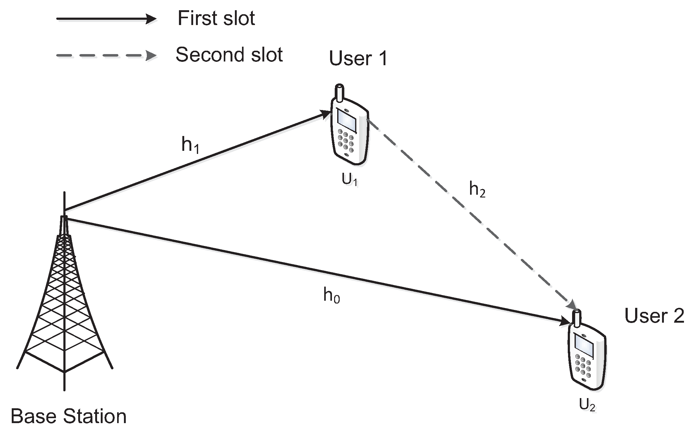
Consider a downlink cooperative NOMA network, which includes the BS, nearby user , and distant user in a cell, as shown in Figure 1. The BS communicates with by utilizing as DF relay. The BS, , and are single-antenna devices and operate in half-duplex mode. Assuming that all wireless links suffer from Nakagami-m fading and additive white Gaussian noise (AWGN) with zero mean and variance . Because there are channel estimation errors in wireless networks with ipCSI, the channel coefficient is denoted by with fading parameter and link average power and is modeled as , , where denotes the estimated channel coefficient and represents the channel estimation error which is subject to Gaussian distribution. , , and denote the channel coefficient of , , and links, respectively, and , , and denote the corresponding estimated channel coefficients. is assumed to be the distance between two nodes, and we have , where represents the path loss exponent. When and are statistically independent, we have estimated link average power . Assuming that represents the relative channel estimation error, we can obtain and .
The BS communicates with distant user through direct link and relaying link in a cell. DF protocol is used for the relaying link where nearby user acts as user relaying. Two consecutive slots are involved in the whole communication process. In the first slot, the BS transmits superposed signal to relaying user and distant user according to the principle of NOMA, where is the normalized transmission power at the BS, and are the normalized unit power signals of and , respectively, and and are the corresponding power allocation coefficients. Assuming that and . The received signals at and are given by
and
respectively, where and are AWGN at and respectively.
According to NOMA scheme, the nearby user with better channel conditions is allocated less transmit power to achieve fairness between users. Based on the assumption of power allocation coefficients, the signal of is decoded firstly by exploiting successive interference cancellation from the received superposed signal at , where with more transmit power has less the inter-user interference. The received signal to interference and noise ratio (SINR) for to decode signal of can be expressed as
where is the transmit signal to noise ratio (SNR). Since imperfect successive interference cancellation (ipSIC) is performed, signal is not completely canceled out from the received superposed signal of after decoding it, there is residual interference (RI). The received SINR for to decode its own signal is given by
where represents the impact level of RI. only needs to treat signal of as noise to decode its own signal. The received SINR for to decode its own signal is given by
In the second slot, relaying user forwards signal decoded from the original superposed signal to . The received signal at for relaying link is written as
where is the normalized transmission power at . For simplicity, we set . The received SINR for to decode signal for relaying link is given by
Hence receives signals from two different links of direct link in the first slot and relaying link in the second slot. The total received signal at is expressed as
The received SINR after selection combining (SC) at is given by
3. Outage Performance Evaluation
In this section, the outage behaviors of downlink cooperative NOMA networks with ipCSI over Nakagami-m fading channels are analyzed in the following two scenarios.
3.1. User Relaying without Direct Link
In this subsection, the first scenario is investigated in terms of outage probability and diversity order, where the BS communicates with via relaying link and serves as user relaying to decode and forward the information to .
3.1.1. Exact Outage Probability
The estimated channel coefficient is subject to Nakagami-m distribution, thus the estimated channel gain is subject to Gamma distribution with the fading parameter and the estimated link average power , , and its PDF and CDF can be expressed as
where and denote the Gamma function and the incomplete Gamma function ([23], eq.(8.310.1), eq.(8.350.1)), respectively. When takes an integer value greater than or equal to one, we have and ([23], eq.(8.339.1), eq.(8.352.6)). The physical meaning of Equations (10) and (11) are PDF and CDF that the channels suffer from Nakagami-m fading, respectively. Assuming that fading parameter is an integer value greater than or equal to one, we can rewrite and as
In the first scenario, the complementary events of outage occur at when can successfully decode the signal and its own signal . Based on this explanation, the outage probability of can be expressed as
where and represent the target SNRs at to decode and , respectively. and denote the corresponding target rates.
The exact expression for the outage probability of is presented in the following theorem.
Theorem 1.
The closed-form expression for the outage probability ofcan be derived as
where,,,, and. Note that (15) is obtained under the conditions of and . The physical meaning of Equation (15) is the probability that the outage occurs for relaying user over Nakagami-m fading channels in wireless communication networks, in other words, the probability that fails to decode the signal of distant user and/or its own signal .
Proof.
In the first scenario, the outage events of occur if one of the following two events is satisfied. The first event is that fails to decode the signal . The second event is that fails to decode its own signal when can successfully decode the signal . Based on the above events, the outage probability of can be expressed as
The exact expression for the outage probability of in the first scenario is presented in the following theorem.
Theorem 2.
The closed-form expression for the outage probability ofin the first scenario can be derived as
where,, and. The physical meaning of Equation (18) is the probability that the outage occurs for distant user over Nakagami-m fading channels in the first scenario, in other words, the probability that relaying user fails to decode the signal of or fails to decode its own signal when can successfully decode the signal .
3.1.2. Diversity Analysis
In the first scenario, in order to better understand the outage behavior of the network, the expressions of the approximate outage probability for a pair of NOMA users are derived at high SNR, from which the diversity order achieved by the network can be attained. The diversity order is defined as
The physical meaning of Equation (20) is the number of branches that the signal is independently fading in the transmission process, which is shown as the slope of outage probability curve at high SNR.
We rewrite the outage probability expressions of and as follows:
At high SNR region (), it produces
where , , and . Applying the above approximations, we get
where and . Substituting (27)–(30) into (21) and (22), the approximate outage probabilities of and at high SNR are obtained as follows
Substituting (31) and (32) into (20), the diversity orders and achieved by and are zeros in the first scenario.
From the above analysis, we can observe that , , , and maintain constant with the increase of and when . Hence an error floor appears in the outage probability owing to the existence of channel estimation errors under ipCSI conditions even though the transmit SNR is extremely high. It is worth noting that the error floor results in the diversity order to be zero at high SNR. Hence the error floors for and are and , respectively, which are independent of and .
3.2. User Relaying with Direct Link
In this subsection, we investigate another representative scenario, where the BS communicates with by way of relaying link and direct link. As a result, receives the signals from two different paths and the reliability of the signal received by has been improved. Since the direct link has no effect on , we only investigate the outage performance of .
3.2.1. Exact Outage Probability
In the second scenario, the outage events of occur when one of the following two events happens. The first event is that can successfully decode the signal , but the received SINR of after SC cannot meet its target SNR. The second event is that both and fail to decode the signal . Based on the above events, the outage probability of can be expressed as
The exact expression for the outage probability of in the second scenario is presented in the following theorem.
Theorem 3.
The closed-form expression for the outage probability ofin the second scenario can be derived as
where,,,,,,,,,,,,,,,, and.is the exponential integral function ([23], eq.(8.211.1)). The physical meaning of Equation (34) is the probability that the outage occurs for distant user over Nakagami-m fading channels in the second scenario, in other words, the probability that relaying user can successfully decode the signal of , but the received SINR of after SC cannot meet its target SNR or both and fail to decode the signal .
Proof.
See Appendix A. □
3.2.2. Diversity Analysis
In the second scenario, the approximate outage probability of is derived at high SNR, and the diversity order achieved by is analyzed.
We define the three probabilities based on (33) by , , and , respectively, and rewrite them as follows
When , it yields
and
respectively, where . Using the above approximations, we have
and
respectively, where .
Substituting (12), (39), and (40) into (35), using ([23], eq.(3.351.1)) and the Binomial theorem, the approximation of can be given by
where , , , and .
Using , applying the Binomial theorem and power series, the integration on the right side of (42) can be written as
where .
Using and ([23], eq. (3.351.4)), the integration on the right side of (43) can be calculated as
where , , and .
We substitute (24), (28), (39), and (41) into (36) and (37), the approximations of and can be calculated as
where .
Equations (45)–(47) are substituted into (33), the approximate outage probability of at high SNR is obtained as follows
where . Substituting (48) into (20), the diversity order achieved by is zero in the second scenario.
Similar to the first scenario, , , and remain unchanged as and increase when . Thus there is the error floor for outage probability as a result of channel estimation errors under ipCSI conditions even if is very large, from which the diversity order achieved by is zero at high SNR. Hence the error floor for is , which is independent of and .
4. Numerical Results
In this section, numerical results are presented to evaluate the outage performance of cooperative NOMA networks with ipCSI in terms of outage probability over Nakagami-m fading channels. We use MATLAB programming software for simulation by setting reasonable parameters. The exact expressions for the outage probability are verified by utilizing Monte Carlo simulations. In addition, OMA is regarded as the benchmark to compare with NOMA. Considering that the BS, , and are located in a straight line. Without loss of generality, assuming that the distance between the BS and is normalized to unity, i.e., , and we can obtain , where and are the normalized distance between the BS and , and between and , respectively. In the following simulations, we set the simulation parameters in Table 3.
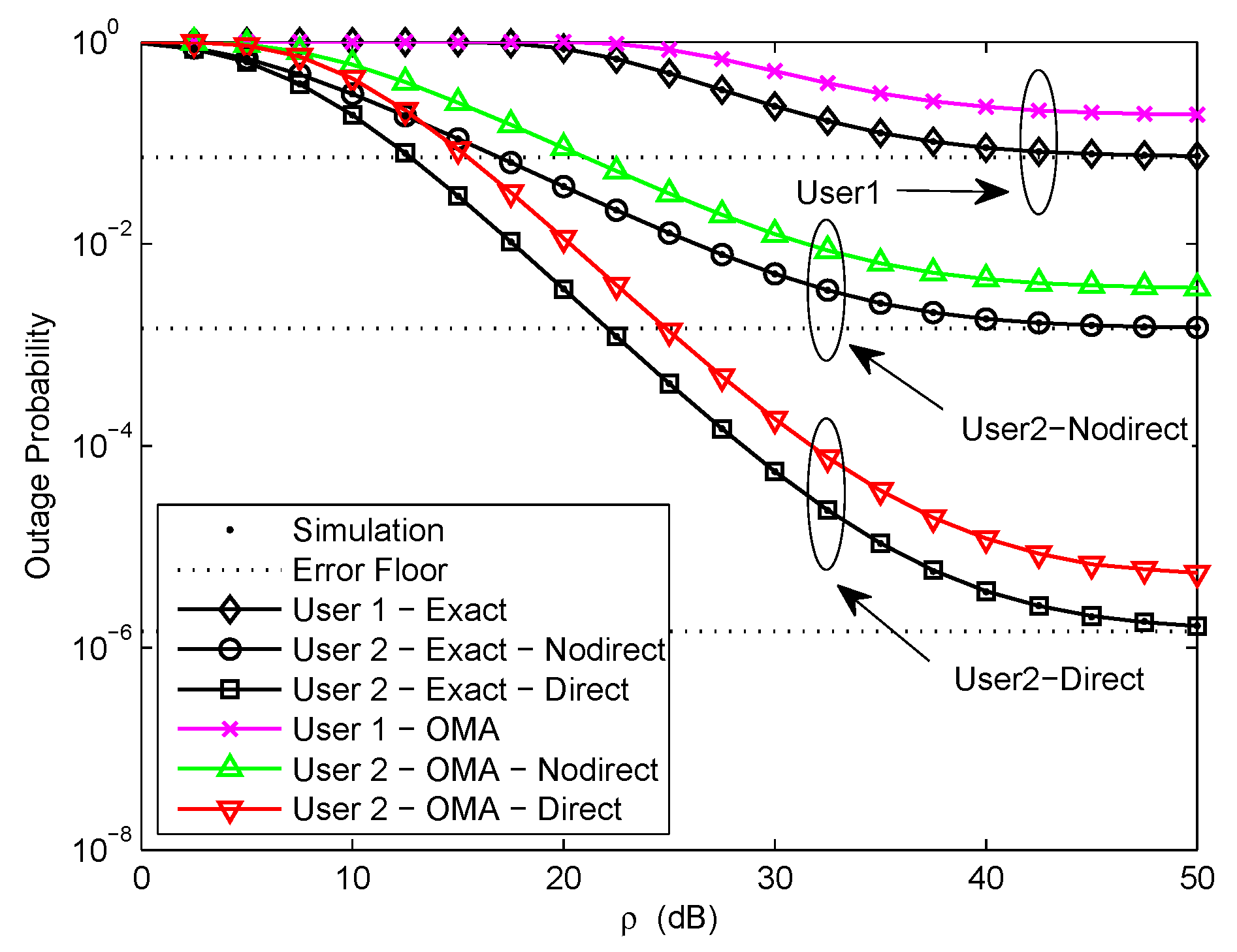
Figure 2 plots the outage probability of a pair of users for the two scenarios versus the transmit SNR. We assume , , and . The target rate is set to be , bit per channel use (BPCU) for and , respectively. The exact outage probability curves of a pair of users for the two scenarios are plotted according to (15), (18), and (34), respectively. We can easily observe that the exact outage probability curves and the Monte Carlo simulation results match well. It can be seen that the outage performance of NOMA outperforms OMA. It is the fact that the superposition coding scheme is performed at the transmitter in NOMA networks, multiple users can be served by sharing the same physical resource. To ensure user fairness, the target rate of OMA user is larger than that of NOMA user. The approximate outage probability curves of a pair of users for the two scenarios are plotted according to (31), (32), and (48), respectively. It is observed that the outage probability decreases as the transmit SNR increases at low SNR and reaches a fixed value at high SNR. The error floor exists at high SNR owing to the channel estimation errors, which leads zero diversity order. Another important observation is that the outage probability of with direct link in the second scenario is much better than that of without direct link in the first scenario and the error floor gap is about 3 orders of magnitude. Because only receives the signal from relaying link in the first scenario, but receives the signals from relaying link and direct link in the second scenario, thus the reliability of the signal received by in the second scenario has been improved.
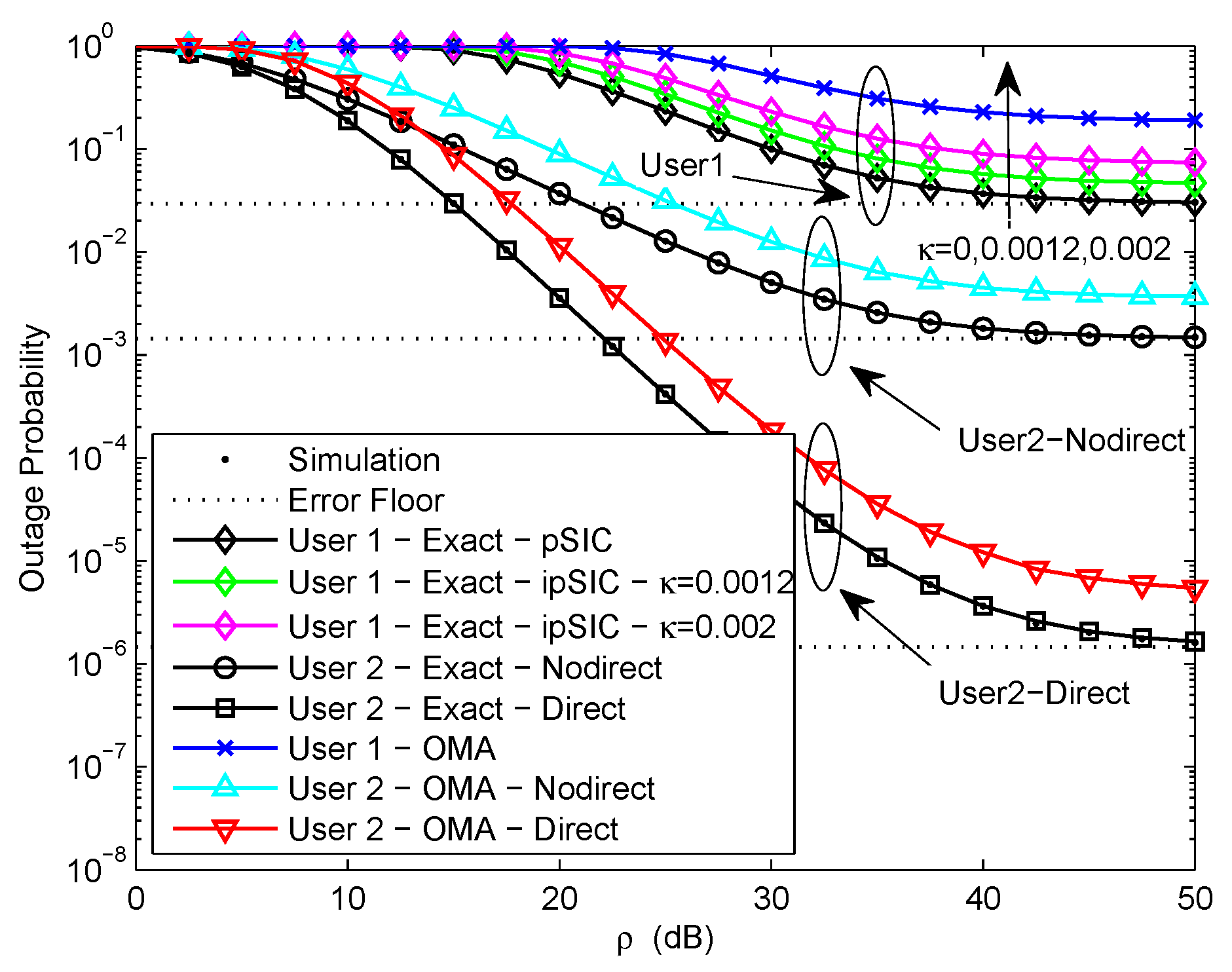
Figure 3 plots the outage probability of a pair of users for the two scenarios versus the transmit SNR with different levels of RI from 0 to 0.002. We assume , , , and . Obviously, the exact outage probability curves match perfectly with the Monte Carlo simulation results. We observe that NOMA is capable of achieving better outage performance than OMA. This is caused by the superposition coding scheme. Considering the impact of RI caused by ipSIC at user , the outage probability of with different levels of RI is plotted based on (15). It can be observed that the RI-based exact outage probability curves of reduce with the increase of the transmit SNR in low SNR region and an error floor appears in high SNR region. This is due to the existence of channel estimation errors, resulting in zero diversity order. More importantly, it is shown that the effect of RI on the outage performance of is very obvious. The outage performance of reduce significantly increasing the levels of RI from 0 to 0.002. This is because the larger the levels of RI, the greater the interference of , hence the outage performance of becomes worse. Therefore, it is extremely important to consider the effect of RI in practical ipSIC systems.
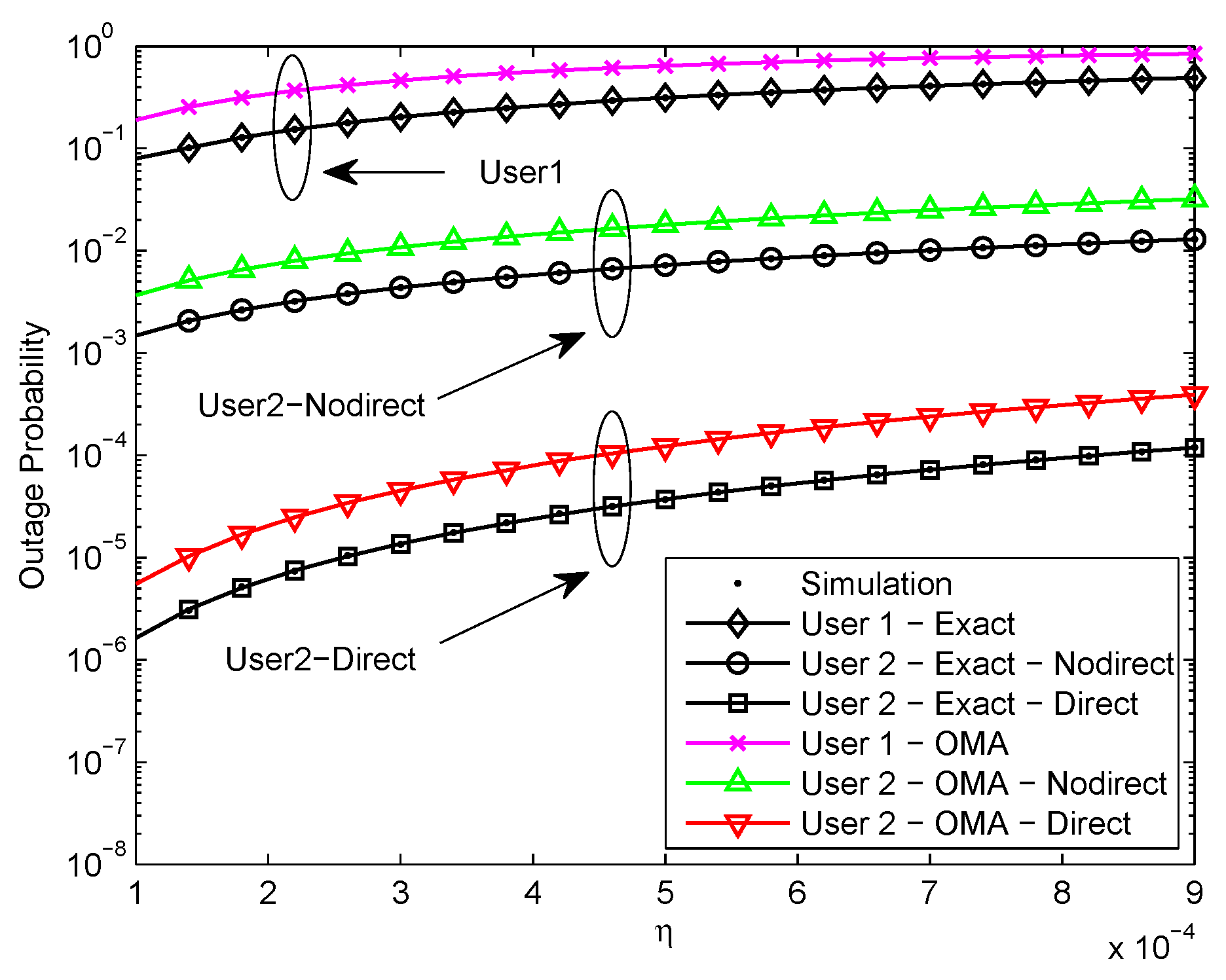
Figure 4 plots the outage probability of a pair of users for the two scenarios versus the relative channel estimation error. We assume , , , dB, and . We can see that the exact outage probability curves and the Monte Carlo simulation results are in excellent agreement. One can observe that the outage performance of NOMA is superior to OMA. It is due to the superposition coding scheme. Moreover, it is observed that the outage probability increases as the relative channel estimation error increases due to the impact of error floor. In addition, it is worth noting that the outage performance of with direct link in the second scenario exceeds without direct link in the first scenario and the outage performance gap is about 3 orders of magnitude.It is that only receives the signal from relaying link in the first scenario, but receives the signals from two different paths in the second scenario, thus the performance of in the second scenario is much better.
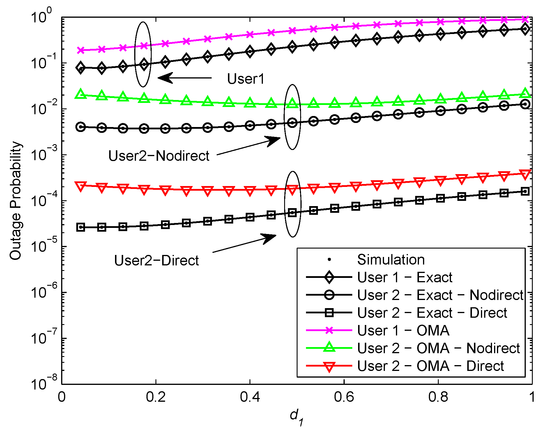
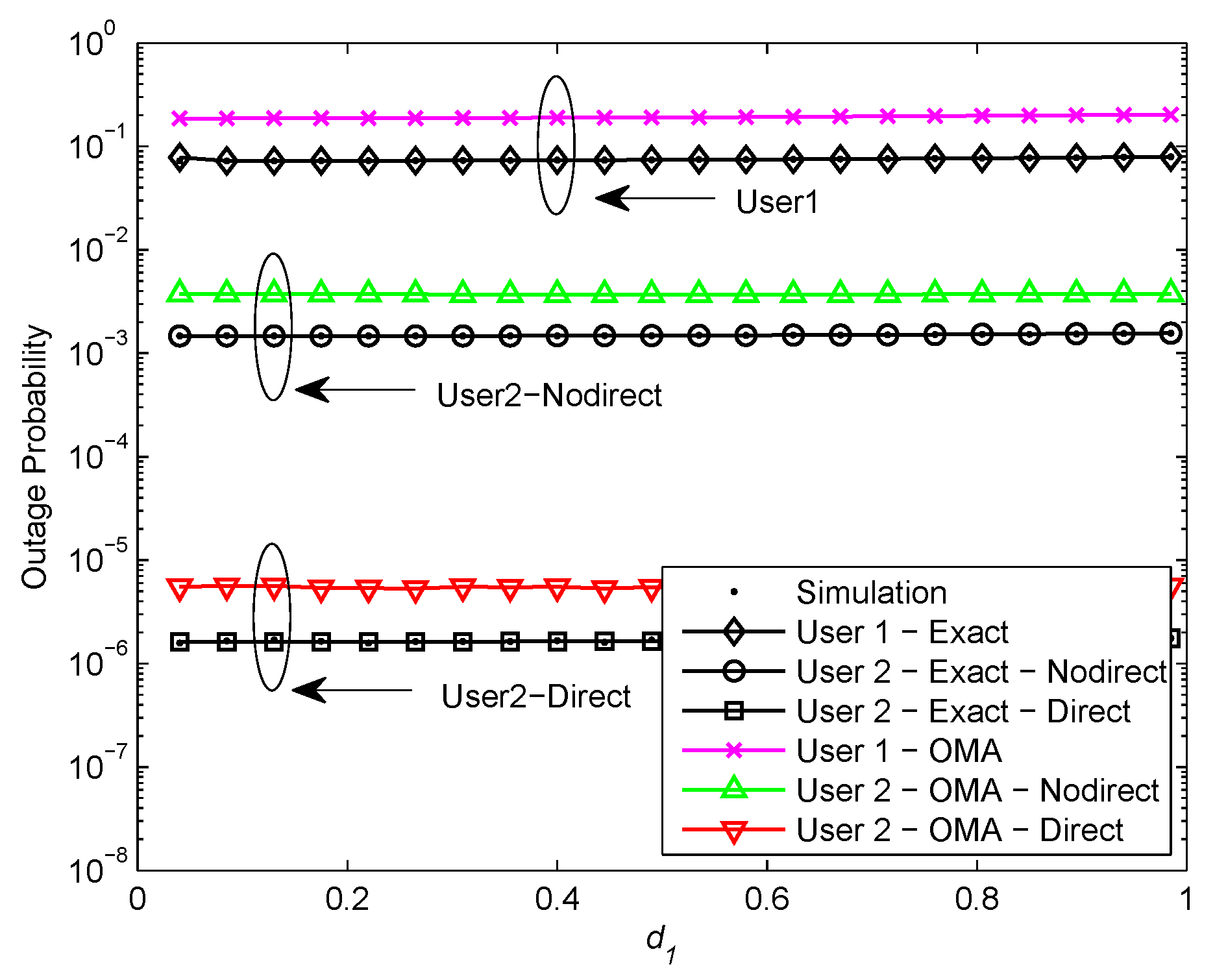
Figure 5 and Figure 6 plot the outage probability of a pair of users for the two scenarios versus the normalized distance between BS and for and dB, respectively. We assume , , , and . In Figure 5, it is shown that the exact outage probability curves match precisely with the Monte Carlo simulation results. We observe that the optimal location for user relaying is closer to the BS than . The reason is that with better channel condition is allocated less transmit power, the optimal location for should be nearer to the BS in order to achieve high received SNR at . Furthermore, it can be observed that the outage performance of NOMA exceeds OMA. That is owing to the superposition coding scheme. It is worth pointing out that the outage performance declines as gets close to and the outage performance gap between NOMA and OMA is no longer apparent. It is the fact that with better channel condition is allocated less transmit power, the received SNR at reduces as gets close to . Therefore, the user relaying location for cooperative NOMA networks should be near to the BS. Additionally, it is observed that the outage performance of with direct link in the second scenario outperforms without direct link in the first scenario and the outage performance gap is about 2 orders of magnitude. Since in the second scenario has more paths to receive signals than in the first scenario. In Figure 6, it can be seen that the outage probability maintains constant as the user relaying location increases. This phenomenon can be explained that the outage probability achieves the error floor at high SNR which is independent of and .
5. Conclusions
This paper has investigated the downlink cooperative NOMA network with ipCSI over Nakagami-m fading channels. The outage performance of two cooperative relaying scenarios is analyzed in detail. We derive the closed-form expressions for the exact outage probability to characterize the outage behavior of the network. Then the expressions for the approximate outage probability at high SNR are derived, from which the diversity order achieved by the network is zero due to the effect of channel estimation errors. Simulation results demonstrate that NOMA is superior to OMA in terms of outage probability. It can be seen that an error floor appears in the outage probability at high SNR. Furthermore, the optimal user relaying location for cooperative NOMA networks should be close to the BS. The outage performance of the distant user can be greatly improved by using the direct link between the BS and distant user. Our future work will relax the assumption of half-duplex mode, impact of loop interference on system performance will be investigated under ipCSI in full-duplex mode.
Author Contributions
Conceptualization, X.G., X.Y. and F.L.; Methodology, X.G., X.Y. and F.L.; Software, X.G. and X.Y.; Writing—Original Draft Preparation, X.G. and X.Y.; Writing—Review & Editing, X.G., X.Y. and F.L. All authors have read and agreed to the published version of the manuscript.
Funding
This work was supported by the National Natural Science Foundation of China under Grant Nos. 91538202, 91638301 and 91738301. The work of X.Y. was supported in part by the Science and Technology Project of Beijing Municipal Education Commission under grants (KM202011232003), in part by the Key Research and Cultivation Project at Beijing Information Science and Technology University under grants (5211910924), in part by the Supplementary and Supportive Project for Teachers at Beijing Information Science and Technology University under grants (5111911147).
Conflicts of Interest
The authors declare no conflict of interest.
Appendix A
Proof of Theorem 3.
According to (33), the outage probability of in the second scenario is expressed as
Using ([23], eq.(3.351.1)) and the Binomial theorem, can be given by
where and . Furthermore, using , can be calculated as
where . Applying the Binomial theorem and power series, can be written as
Using and [23, eq.(3.351.4)], is calculated as
where , , and .
References
- Li, Q.C.; Niu, H.; Papathanassiou, A.T.; Wu, G. 5G network capacity: Key elements and technologies. IEEE Veh. Technol. Mag. 2014, 9, 71–78. [Google Scholar] [CrossRef]
- Ding, Z.; Lei, X.; Karagiannidis, G.K.; Schober, R.; Yuan, J.; Bhargava, V.K. A survey on non-orthogonal multiple access for 5G networks: Research challenges and future trends. IEEE J. Sel. Areas Commun. 2017, 35, 2181–2195. [Google Scholar] [CrossRef] [Green Version]
- Liu, Y.; Qin, Z.; Elkashlan, M.; Ding, Z.; Nallanathan, A.; Hanzo, L. Non-orthogonal multiple access for 5G and beyond. Proc. IEEE 2017, 105, 2347–2381. [Google Scholar] [CrossRef] [Green Version]
- Ding, Z.; Liu, Y.; Choi, J.; Sun, Q.; Elkashlan, M.; Chih-Lin, I.; Poor, H.V. Application of non-orthogonal multiple access in LTE and 5G networks. IEEE Commun. Mag. 2017, 55, 185–191. [Google Scholar] [CrossRef] [Green Version]
- Cover, T.M.; Thomas, J.A. Elements of Information Theory, 6th ed.; Wiley: New York, NY, USA, 1991. [Google Scholar]
- Ding, Z.; Peng, M.; Poor, H.V. Cooperative non-orthogonal multiple access in 5G systems. IEEE Commun. Lett. 2015, 19, 1462–1465. [Google Scholar] [CrossRef] [Green Version]
- Liu, Y.; Ding, Z.; Elkashlan, M.; Poor, H.V. Cooperative non-orthogonal multiple access with simultaneous wireless information and power transfer. IEEE J. Sel. Areas Commun. 2016, 34, 938–953. [Google Scholar] [CrossRef] [Green Version]
- Zhang, Z.; Ma, Z.; Xiao, M.; Ding, Z.; Fan, P. Full-duplex device-to-device-aided cooperative nonorthogonal multiple access. IEEE Trans. Veh. Technol. 2017, 66, 4467–4471. [Google Scholar]
- Do, N.T.; Da Costa, D.B.; Duong, T.Q.; An, B. A BNBF user selection scheme for NOMA-based cooperative relaying systems with SWIPT. IEEE Commun. Lett. 2017, 21, 664–667. [Google Scholar] [CrossRef] [Green Version]
- Do, T.N.; da Costa, D.B.; Duong, T.Q.; An, B. Improving the performance of cell-edge users in MISO-NOMA systems using TAS and SWIPT-based cooperative transmissions. IEEE Trans. Green Commun. Netw. 2018, 2, 49–62. [Google Scholar] [CrossRef]
- Yang, Z.; Ding, Z.; Fan, P.; Al-Dhahir, N. The impact of power allocation on cooperative non-orthogonal multiple access networks with SWIPT. IEEE Trans. Wirel. Commun. 2017, 16, 4332–4343. [Google Scholar] [CrossRef] [Green Version]
- Yang, Z.; Ding, Z.; Wu, Y.; Fan, P. Novel relay selection strategies for cooperative NOMA. IEEE Trans. Veh. Technol. 2017, 66, 10114–10123. [Google Scholar] [CrossRef]
- Xu, P.; Yang, Z.; Ding, Z.; Zhang, Z. Optimal relay selection schemes for cooperative NOMA. IEEE Trans. Veh. Technol. 2018, 67, 7851–7855. [Google Scholar] [CrossRef]
- Yue, X.; Liu, Y.; Kang, S.; Nallanathan, A. Performance analysis of NOMA with fixed gain relaying over Nakagami-m fading channels. IEEE Access 2017, 5, 5445–5454. [Google Scholar] [CrossRef] [Green Version]
- Jiao, R.; Dai, L.; Zhang, J.; MacKenzie, R.; Hao, M. On the performance of NOMA-based cooperative relaying systems over Rician fading channels. IEEE Trans. Veh. Technol. 2017, 66, 11409–11413. [Google Scholar] [CrossRef] [Green Version]
- Men, J.; Ge, J.; Zhang, C. Performance analysis for downlink relaying aided non-orthogonal multiple access networks with imperfect CSI over Nakagami-m fading. IEEE Access 2017, 5, 998–1004. [Google Scholar] [CrossRef]
- Benkhelifa, F.; Alouini, M. Precoding design of MIMO amplify-and-forward communication system with an energy harvesting relay and possibly imperfect CSI. IEEE Access 2017, 5, 578–594. [Google Scholar] [CrossRef] [Green Version]
- Men, J.; Ge, J.; Zhang, C. Performance analysis of nonorthogonal multiple access for relaying networks over Nakagami-m fading channels. IEEE Trans. Veh. Technol. 2017, 66, 1200–1208. [Google Scholar] [CrossRef]
- Wan, D.; Wen, M.; Ji, F.; Liu, Y.; Huang, Y. Cooperative NOMA systems with partial channel state information over Nakagami-m fading channels. IEEE Trans. Commun. 2018, 66, 947–958. [Google Scholar] [CrossRef]
- Lv, L.; Ni, Q.; Ding, Z.; Chen, J. Application of non-orthogonal multiple access in cooperative spectrum-sharing networks over Nakagami-m fading channels. IEEE Trans. Veh. Technol. 2017, 66, 5506–5511. [Google Scholar] [CrossRef] [Green Version]
- Hou, T.; Sun, X.; Song, Z. Outage performance for non-orthogonal multiple access with fixed power allocation over Nakagami-m fading channels. IEEE Commun. Lett. 2018, 22, 744–747. [Google Scholar] [CrossRef]
- Yue, X.; Liu, Y.; Kang, S.; Nallanathan, A.; Ding, Z. Exploiting full/half-duplex user relaying in NOMA systems. IEEE Trans. Commun. 2018, 66, 560–575. [Google Scholar] [CrossRef] [Green Version]
- Gradshteyn, I.S.; Ryzhik, I.M. Table of Integrals, Series and Products, 6th ed.; Academic Press: New York, NY, USA, 2000. [Google Scholar]
Figure 1.
Downlink cooperative NOMA networks.

Figure 2.
Outage probability versus transmit signal–noise–ratio (SNR).

Figure 3.
Outage probability versus transmit SNR with different levels of RI.

Figure 4.
Outage probability versus relative channel estimation error.

Figure 5.
Outage probability versus normalized distance between BS and ( = 30 dB).

Figure 6.
Outage probability versus normalized distance between BS and ( = 50 dB).


Table 1.
The comparison of non-orthogonal multiple access (NOMA) and conventional orthogonal multiple access (OMA).
Table 1.
The comparison of non-orthogonal multiple access (NOMA) and conventional orthogonal multiple access (OMA).
| Multiple Access Scheme | NOMA | Conventional OMA |
|---|---|---|
| Aim | Higher spectral efficiency, massive connectivity and user fairness. | Good system throughput, low cost of receiver. |
| Solution | Superposition coding scheme at the transmitter, successive interference cancellation at the receiver and more transmit power is allocated to users with worse channel conditions. | Multiple users are allocated with radio resources which are orthogonal in time, frequency, or code domain. |
| Pros | Multiple users can be served by sharing the same physical resource. The number of supported users or devices is not strictly limited by the amount of available resources and their scheduling granularity. | No interference exists among multiple users. Low complexity of receiver. |
| Cons | Interference exists among multiple users. High complexity of receiver. | A single radio resource can only be allocated to a user. The maximum number of supported users is limited by the total amount and the scheduling granularity of orthogonal resources. |
Table 2.
The main notations used in this paper.
| Notation | Description |
|---|---|
| Probability | |
| Probability density function (PDF) of random variable X | |
| Cumulative distribution function (CDF) of random variable X | |
| Expectation operator | |
| Circularly symmetric complex Gaussian distribution with mean zero and variance | |
| Fading parameter of channel k | |
| Distance between two nodes of channel k | |
| Path loss exponent | |
| Relative channel estimation error of channel k | |
| Transmit signal to noise ratio (SNR) | |
| Impact level of residual interference (RI) | |
| Target rate of user | |
| Target rate of user | |
| Target SNR of user | |
| Target SNR of user |
Table 3.
The simulation parameters.
| Description | NOMA | OMA |
|---|---|---|
| Power allocation coefficient | , | |
| Path loss exponent | ||
| Fading parameter | ||
| Relative channel estimation error | ||
| Distance between two nodes | , , | |
| Impact level of RI | ||
| Transmit SNR | ||
| Target rate | , | , |
© 2020 by the authors. Licensee MDPI, Basel, Switzerland. This article is an open access article distributed under the terms and conditions of the Creative Commons Attribution (CC BY) license (http://creativecommons.org/licenses/by/4.0/).
Share and Cite
MDPI and ACS Style
Gong, X.; Yue, X.; Liu, F. Performance Analysis of Cooperative NOMA Networks with Imperfect CSI over Nakagami-m Fading Channels. Sensors 2020, 20, 424. https://doi.org/10.3390/s20020424
AMA Style
Gong X, Yue X, Liu F. Performance Analysis of Cooperative NOMA Networks with Imperfect CSI over Nakagami-m Fading Channels. Sensors. 2020; 20(2):424. https://doi.org/10.3390/s20020424
Chicago/Turabian StyleGong, Xianli, Xinwei Yue, and Feng Liu. 2020. "Performance Analysis of Cooperative NOMA Networks with Imperfect CSI over Nakagami-m Fading Channels" Sensors 20, no. 2: 424. https://doi.org/10.3390/s20020424
Note that from the first issue of 2016, this journal uses article numbers instead of page numbers. See further details here.