Temperature Effects on Electromechanical Response of Deposited Piezoelectric Sensors Used in Structural Health Monitoring of Aerospace Structures


Abstract
:1. Introduction
2. Materials and Methods
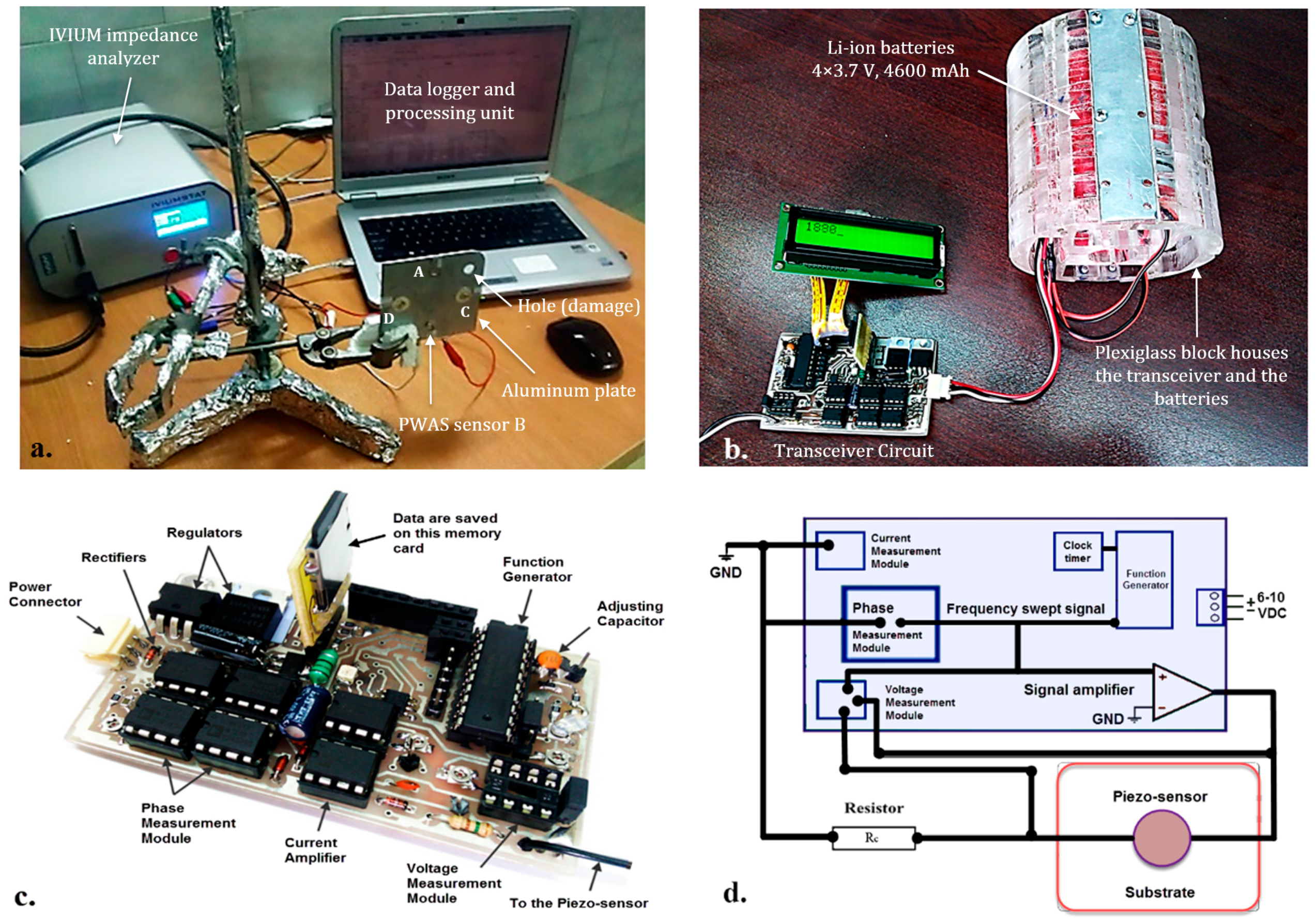
3. Experimental Setup
4. Results and Discussions
4.1. Health Monitoring of Aluminum Plate
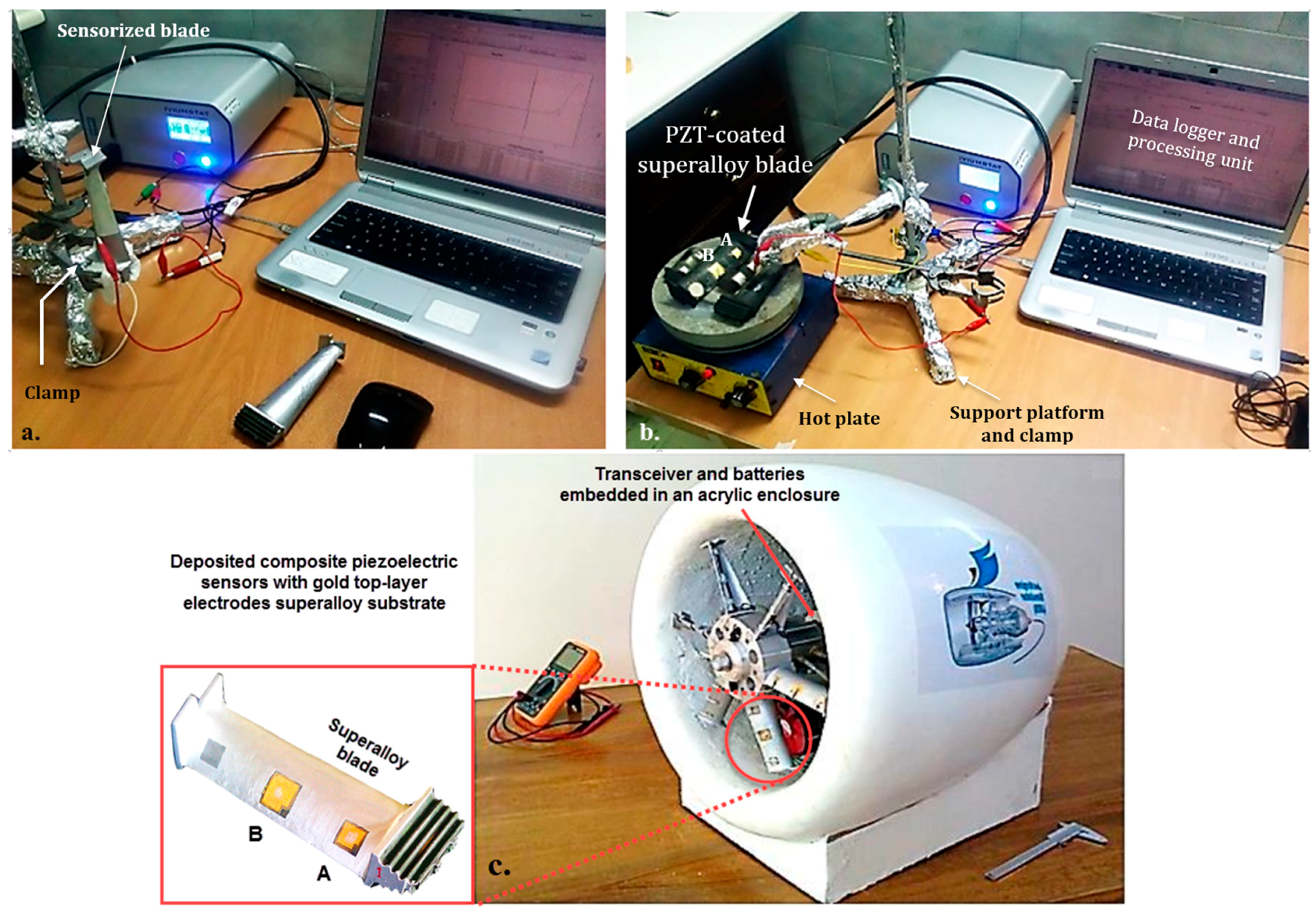
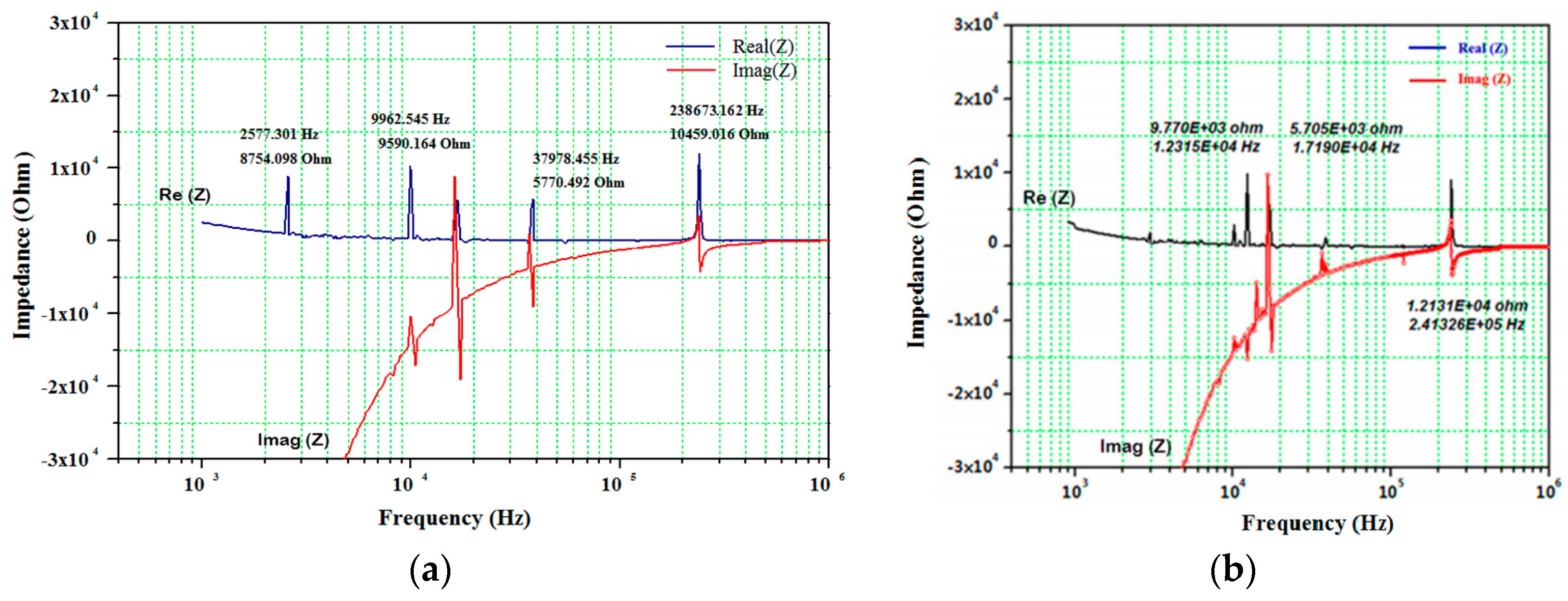
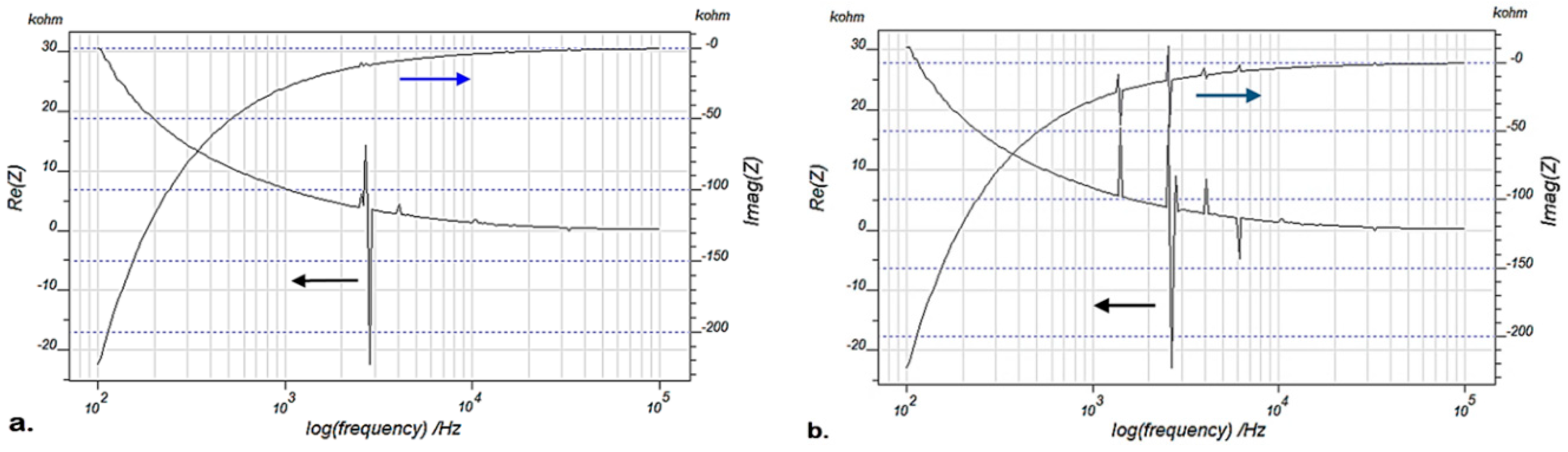
4.2. Health Monitoring of Superalloy Blades
5. Conclusions
Author Contributions
Funding
Conflicts of Interest
References
- Abbas, M.; Shafiee, M. Structural Health Monitoring (SHM) and Determination of Surface Defects in Large Metallic Structures using Ultrasonic Guided Waves. Sensors 2018, 18, 3958. [Google Scholar] [CrossRef] [PubMed]
- Kudela, P.; Radzienski, M.; Ostachowicz, W.; Yang, Z. Structural Health Monitoring system based on a concept of Lamb wave focusing by the piezoelectric array. Mech. Syst. Signal Process. 2018, 108, 21–32. [Google Scholar] [CrossRef]
- Na, W.; Baek, J. A Review of the Piezoelectric Electromechanical Impedance Based Structural Health Monitoring Technique for Engineering Structures. Sensors 2018, 18, 1307. [Google Scholar] [CrossRef] [PubMed]
- Budoya, D.E.; Baptista, F.G. A Comparative Study of Impedance Measurement Techniques for Structural Health Monitoring Applications. IEEE Trans. Instrum. Meas. 2018, 67, 912–924. [Google Scholar] [CrossRef]
- Maruo, I.I.C.; Giachero, G.D.F.; Steffen Júnior, V.; Finzi Neto, R.M. Electromechanical Impedance-Based Structural Health Monitoring Instrumentation System Applied to Aircraft Structures and Employing a Multiplexed Sensor Array. J. Aerosp. Technol. Manag. 2015, 7, 294–306. [Google Scholar] [CrossRef]
- Park, S.; Yun, C.B.; Inman, D.J. Structural health monitoring using electro-mechanical impedance sensors. Fatigue Fract. Eng. Mater. Struct. 2008, 31, 714–724. [Google Scholar] [CrossRef]
- Giurgiutiu, V. Structural Health Monitoring: With Piezoelectric Wafer Active Sensors; Elsevier: Amsterdam, The Netherlands, 2007. [Google Scholar]
- Li, W.; Liu, T.; Zou, D.; Wang, J.; Yi, T.H. PZT based smart corrosion coupon using electromechanical impedance. Mech. Syst. Signal Process. 2019, 129, 455–469. [Google Scholar] [CrossRef]
- Yuanye, B.; Zhang, H. Development and Test of High-Temperature Piezoelectric Wafer Active Sensors for Structural Health Monitoring. Master’s Thesis, University of North Texas, Denton, TX, USA, 2014. [Google Scholar]
- Dhutti, A.; Tumin, S.A.; Gan, T.H.; Kanfoud, J.; Balachandran, W. Comparative study on the performance of high temperature piezoelectric materials for structural health monitoring using ultrasonic guided waves. In Proceedings of the 7th Asia-Pacific Workshop on Structural Health Monitoring, Hong Kong, China, 12–15 November 2018; pp. 12–15. [Google Scholar]
- Giurgiutiu, V.; Xu, B.; Liu, W. Development and Testing of High-temperature Piezoelectric Wafer Active Sensors for Extreme Environments. Struct. Health Monit. 2010, 9, 513–525. [Google Scholar] [CrossRef]
- Kamas, T.; Poddar, B.; Lin, B.; Yu, L.L. Assessment of Temperature Effect in Structural Health Monitoring with Piezoelectric Wafer Active Sensors. Smart Struct. Syst. 2015, 16, 835–851. [Google Scholar] [CrossRef]
- Lissenden, C.J.; Tittmann, B.R. Temperature Resistant Spray-on Piezoelectric Transducers for Materials Characterization with Ultrasonic-Guided Waves. Adv. Sens. Instrum. Newsl. 2015, 3, 1–4. [Google Scholar]
- McNab, A.; Kirk, K.J.; Cochran, A. Ultrasonic transducers for high temperature applications. IEEE Proc. Sci. Meas. Technol. 1998, 145, 229–236. [Google Scholar] [CrossRef]
- Hooker, M.W. Properties of PZT-Based Piezoelectric Ceramics Between −150 and 250 C. Technical Report NASA/CR-1998-208708; Langley Research Center: Hampton, VI, USA, September 1998. [Google Scholar]
- Park, G.; Cudney, H.H.; Inman, D.J. Impedance-based health monitoring technique for massive structures. In Smart Structures and Materials 1999: Sensory Phenomena and Measurement Instrumentation for Smart Structures and Materials; SPIE: Bellingham, WA, USA, 1999; Volume 3670, pp. 461–470. [Google Scholar]
- Konstantinidis, G.; Wilcox, P.D.; Drinkwater, B.W. An Investigation into the Temperature Stability of a Guided Wave Structural Health Monitoring System Using Permanently Attached Sensors. IEEE Sens. J. 2007, 7, 905–912. [Google Scholar] [CrossRef]
- Kažys, R.J.; Voleišis, A.; Voleišienė, B. High temperature ultrasonic transducers. Ultragarsas 2008, 63, 7–17. [Google Scholar]
- Akiyama, M.; Kamohara, T.; Kano, K.; Teshigahara, A.; Takeuchi, A.; Kawahara, Y. Enhancement of Piezoelectric Response in Scandium Aluminum Nitride Alloy Thin Films Prepared by Dual Reactive Cosputtering. Adv. Mater. 2009, 21, 593–596. [Google Scholar] [CrossRef] [PubMed]
- Krsmanovic, D. High Temperature Ultrasonic Gas Flow Sensor Based On Lead Free Piezoelectric Material. Ph.D. Thesis, University of Cambridge, Cambridge, UK, 2011. [Google Scholar]
- Baptista, F.G.; Budoya, D.E.; de Almeida, V.A.D.; Ulson, J.A.C. An Experimental Study on the Effect of Temperature on Piezoelectric Sensors for Impedance-Based Structural Health Monitoring. Sensors 2014, 14, 1208–1227. [Google Scholar] [CrossRef] [PubMed]
- Koo, K.; Park, S.; Lee, J.; Yun, C. Automated impedance-based structural health monitoring incorporating effective frequency shift for compensating temperature effects. J. Intell. Mater. Syst. Struct. 2009, 20, 367–377. [Google Scholar] [CrossRef]
- Yun, C.; Cho, S.; Park, H.; Min, J.; Park, J. Smart wireless sensing and assessment for civil infrastructure. Struct. Infrastruct. Eng. 2014, 10, 534–550. [Google Scholar] [CrossRef]
- Balmès, E.; Guskov, M.; Rebillat, M.; Mechbal, N. Effects of temperature on the impedance of piezoelectric actuators used for SHM. In Proceedings of the 14th Symposium on Vibration, Shock and Noise (VISHNO), Aix en Provence, France, 17–19 June 2014; pp. 1–6. [Google Scholar]
- Li, Y.H.; Jong, K.S.; Salowitz, N.; Chang, F.K. Development of High-Performance BS-PT Based Piezoelectric Transducers for High-Temperature Applications. In Proceedings of the EWSHM-7th European Workshop on Structural Health Monitoring, Nantes, France, 8–11 July 2014. [Google Scholar]
- Malarich, N. Spray-on Comb Transducers for Health Monitoring of High Temperature Structures. Baccalaureate Thesis, Schreyer Honors College, The Pennsylvania State University, University Park, PA, USA, 2015. [Google Scholar]
- Eason, T.J.; Bond, L.J.; Lozev, M.G. Ultrasonic Sol-Gel Arrays for Monitoring High Temperature Corrosion. In Proceedings of the 19th World Conference on Non-Destructive Testing, Munich, Germany, 13–17 June 2016. [Google Scholar]
- Zhang, C.; Zhang, H. Performance enhanced piezoelectricbased crack detection system for high temperature I-beam SHM. In Nondestructive Characterization and Monitoring of Advanced Materials, Aerospace, and Civil Infrastructure; SPIE: Bellingham, WA, USA, 2017; p. 101691Y. [Google Scholar]
- Prowant, M.S.; Dib, G.; Qiao, H.; Good, M.S.; Larche, M.R.; Sexton, S.S.; Ramuhalli, P. Preliminary design of high temperature ultrasonic transducers for liquid sodium environments. In AIP Conference Proceedings; AIP Publishing: Melville, NY, USA, 2018; Volume 1949, p. 100006. [Google Scholar]
- Hoshyarmanesh, H.; Nehzat, N.; Salehi, M.; Ghodsi, M. X-ray diffraction measurement of residual stress in sol-gel grown lead zirconate titanate thick films on nickel-based super alloy substrate. J. Mech. Sci. Technol. 2015, 29, 715–721. [Google Scholar] [CrossRef]
- Hoshyarmanesh, H.; Nehzat, N.; Salehi, M.; Ghodsi, M.; Lee, H.S.; Park, H.H. Thickness and thermal processing contribution on piezoelectric characteristics of Pb(Zr-Ti)O3 thick films deposited on curved IN738 using sol–gel technique, Proceedings of the Institution of Mechanical Engineers, Part L. J. Mater. Des. Appl. 2015, 229, 511–521. [Google Scholar]
- Hoshyarmanesh, H.; Ghodsi, M.; Park, H.H. Electrical properties of UV-irradiated thick film piezo-sensors on superalloy IN718 using photochemical metal organic deposition. Thin Solid Films 2016, 616, 673–679. [Google Scholar] [CrossRef]
- Hoshyarmanesh, H.; Abbasi, A.; Moein, P.; Ghodsi, M.; Zareinia, K. Design and implementation of an accurate, portable, and time-efficient impedance-based transceiver for structural health monitoring. IEEE ASME Trans. Mechatron. 2017, 22, 2809–2814. [Google Scholar] [CrossRef]
- Hoshyarmanesh, H.; Ebrahimi, N.; Jafari, A.; Hoshyarmanesh, P.; Kim, M.J.; Park, H.H. PZT/PZT and PZT/BiT Composite Piezo-Sensors in Aerospace SHM Applications: Photochemical Metal Organic + Infiltration Deposition and Characterization. Sensors 2019, 19, 13. [Google Scholar] [CrossRef] [PubMed]
- Yoo, J. High Dielectric and Piezoelectric Properties of Low-Temperature Sintering PNN-PMN-PZT Ceramics for Low-Loss Piezoelectric Actuator Application. Trans. Electr. Electron. Mater. 2018, 19, 249–253. [Google Scholar] [CrossRef]
- Hoshyarmanesh, H.; Maddahi, Y. Poling Process of Composite Piezoelectric Sensors for Structural Health Monitoring: A Pilot Comparative Study. IEEE Sens. Lett. 2018, 2, 1–4. [Google Scholar] [CrossRef]
- Hoshyarmanesh, H.; Abbasi, A.H. Structural health monitoring of rotary aerospace structures based on electromechanical impedance of integrated piezoelectric transducers. J. Intell. Mater. Syst. Struct. 2018, 29, 1799–1817. [Google Scholar] [CrossRef]
- Allianz, V.A.G. Handbook of Loss Prevention; Springer: New York, NY, USA, 1978. [Google Scholar]
- Dundas, R.E. A statistical study of gas turbine losses and analysis of causes and optimum methods of prevention. In Proceedings of the ASME International Gas Turbine and Aeroengine Congress, The Hague, The Netherlands, 13–16 June 1994; Volume 4, pp. 13–16. [Google Scholar]
- Jung, J. Turbine Operational Problems. Nuclear Training Course 234: Turbine and Auxiliaries (Module 14 Ref. 23004); CANTEACH: Hamilton, ON, Canada, 1994. [Google Scholar]
- Witos, M.; Wachlaczenko, M. Expert System to Support Operational Safety of the TS-11 Iskra Aircraft and Overhauls of the SO−3 Engines. In Proceedings of the 7th International Symposium on NDT in Aerospace, Bremen, Germany, 16–18 November 2015; pp. 16–18. [Google Scholar]
- Logan, E., Jr. Handbook of Turbomachinery; CRC Press: Boca Raton, FL, USA, 1995. [Google Scholar]
- Shaniavski, A.A. Tolerance Fatigue Cracking of Aircraft Components. Synergetics in Engineering Application; Scientific & Technical Literature Publishing House: Ufa, Russia, 2003. [Google Scholar]
- Rolls Royce, P. The Jet Engine, 5th ed.; John Wiley & Sons: West Sussex, UK, 2015. [Google Scholar]
- Giurgiutiu, V. Structural Health Monitoring with Piezoelectric Wafer Active Sensors, 2nd ed.; Academic Press: Cambridge, MA, USA, 2014. [Google Scholar]
- Giurgiutiu, V. Structural Health Monitoring of Aerospace Composites; Academic Press: Cambridge, MA, USA, 2015. [Google Scholar]
- Khan, A.S.; Balzer, J.E.; Wilgeroth, J.M.; Proud, W.G. Temperature effects on the mechanical behaviour of PZT 95/5. J. Phys. Conf. Ser. 2014, 500, 112038. [Google Scholar] [CrossRef]
- Fukuhara, M.; Sanpei, A. Elastic moduli and internal frictions of Inconel 718 and Ti-6AI-4V as a function of temperature. J. Mater. Sci. Lett. 1993, 12, 1122–1124. [Google Scholar] [CrossRef]


| Monitoring Condition | L1 (PZT/BiT) 10 × 10 mm | L3 ((PZT/PZT) 10 × 10 mm | |||||||||||
|---|---|---|---|---|---|---|---|---|---|---|---|---|---|
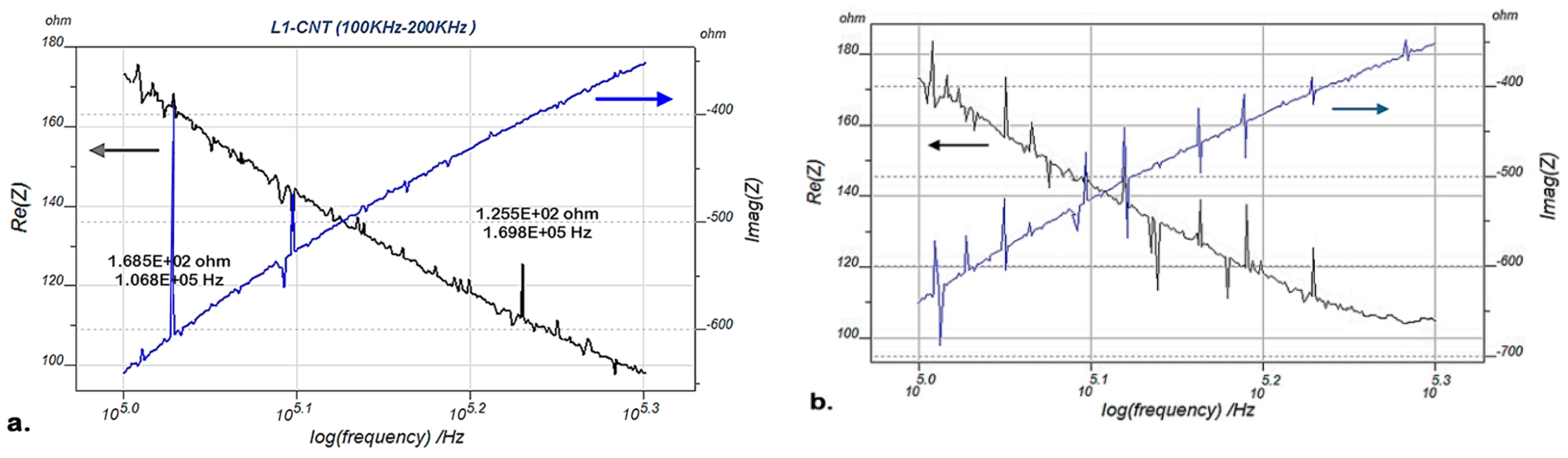
| Pristine AT* | Frequency (kHz ±5%) | 2.8 | 106.8 | 123.6 | 144.2 | 169.8 | --- | 11.2 | 122.9 | 176.6 | 188.1 | 237.0 | --- |
| Pristine HT* | 2.8 | 105.5 | --- | 140.7 | --- | --- | 10.2 | 120.2 | --- | 184.3 | --- | --- | |
| Damaged AT | 2.6 | 102.1 | 112.5 | 132.3 | 155.8 | 171.7 | 6.0 | 116.7 | 167.3 | 179.5 | 225.8 | 537.5 | |
| Damaged HT | 2.6 | 99.7 | --- | 127.3 | --- | --- | 4.8 | 109.5 | 137.5 | 141.8 | 173.3 | --- | |
| Pristine AT | EMI (Ω ±2%) | 14800 | 168.5 | 145.1 | 131.3 | 125.5 | --- | 3450 | 241 | 420.0 | 114.5 | 55.9 | --- |
| Pristine HT | 12880 | 134.4 | --- | 106.9 | --- | --- | 3105 | 207 | --- | 92.7 | --- | --- | |
| Damaged AT | 17400 | 184.8 | 173.9 | 148.4 | 138.2 | 124.3 | 4100 | 331 | 484.2 | 235.9 | 98.4 | 158.3 | |
| Damaged HT | 16320 | 161.4 | --- | 122.1 | --- | --- | 4018 | 314 | 445.1 | 214.2 | 88.1 | --- | |
| Monitoring Condition | L4 (PZT/BiT) 10 × 10 mm | L2 (PZT/PZT) 10 × 10 mm | |||||||||||
|---|---|---|---|---|---|---|---|---|---|---|---|---|---|
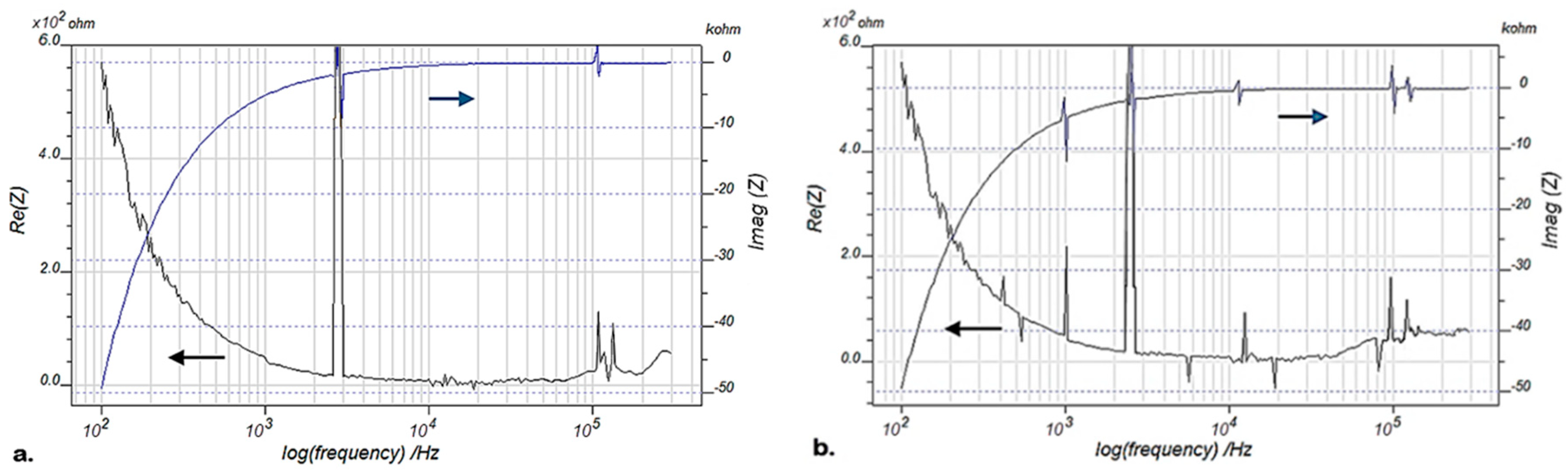
| Pristine AT* | Frequency (kHz ±5%) | 3.0 | 98.5 | 116.4 | 158.4 | 191.8 | 2.9 | 4.0 | 13.9 | --- | --- | --- | --- |
| Pristine HT* | 2.9 | 97.8 | --- | 159.0 | --- | 2.7 | 3.5 | 13.0 | --- | --- | --- | --- | |
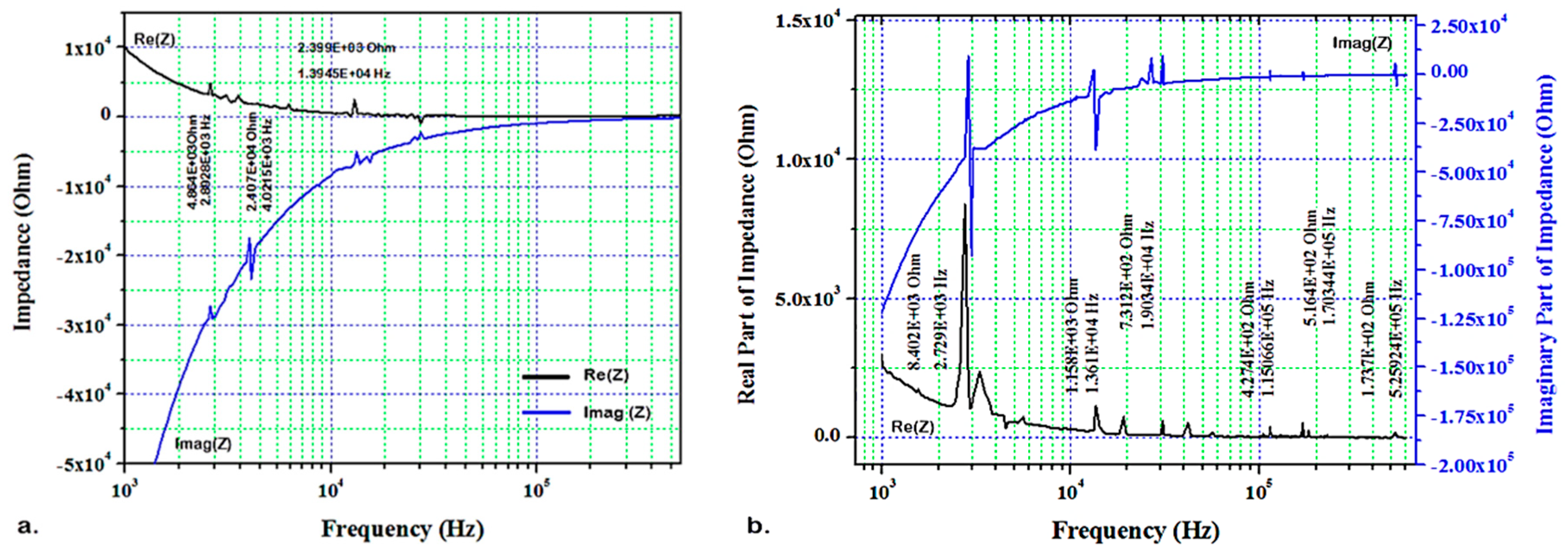
| Damaged AT | 2.6 | 96.0 | 116.0 | 156.1 | 178.2 | 2.7 | 3.3 | 13.6 | 19.0 | 115.0 | 170.3 | 525.9 | |
| Damaged HT | 2.6 | 94.8 | --- | 139.9 | --- | 2.6 | 3.3 | 11.1 | --- | 106.0 | 170.4 | --- | |
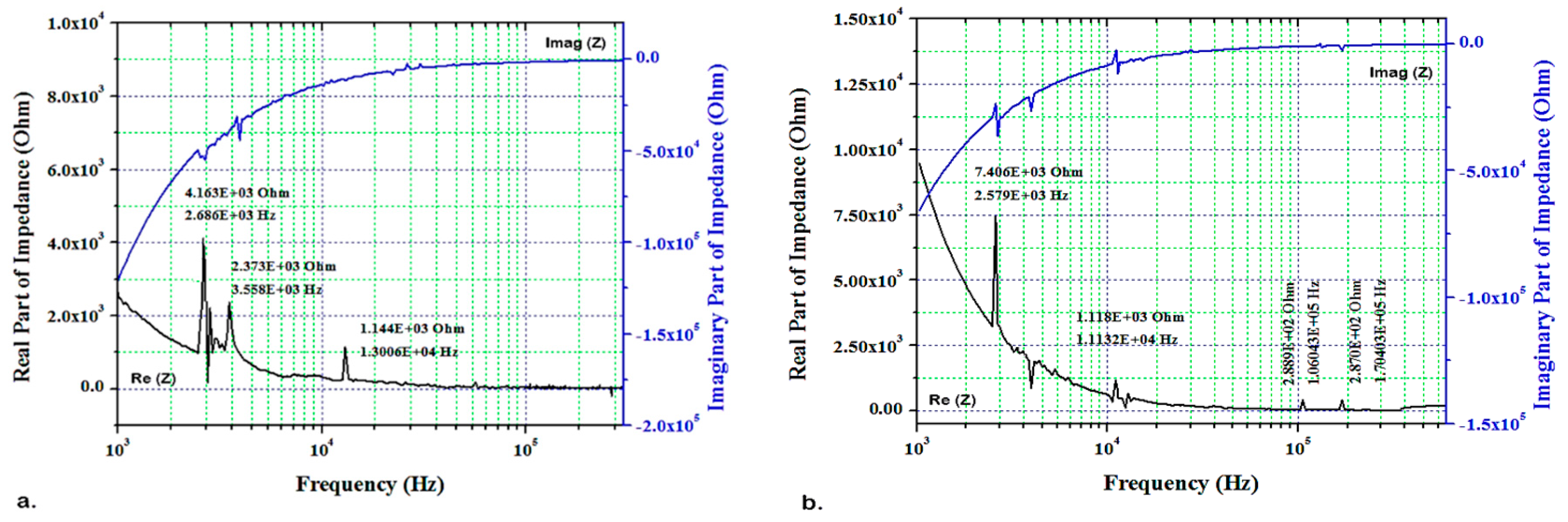
| Pristine AT | EMI (Ω ±2%) | 12723 | 180.4 | 147.5 | 129.6 | 119.6 | 4864.4 | 2407.6 | 2399.0 | --- | --- | --- | --- |
| Pristine HT | 11580 | 151.7 | --- | 111.5 | --- | 4163.1 | 2373.5 | 1144.8 | --- | --- | --- | --- | |
| Damaged AT | 13486 | 204.1 | 188.0 | 152.5 | 108.0 | 8402.3 | 2491.5 | 1158.1 | 731.2 | 427.4 | 516.4 | 173.7 | |
| Damaged HT | 13024 | 190.5 | --- | 131.2 | --- | 7406.8 | 2483.2 | 1118.0 | --- | 288.9 | 287.0 | --- | |
| Impedance Analyzer | Blade L1 | Blade L3 | |||||||
|---|---|---|---|---|---|---|---|---|---|
| Pristine | Damaged | Pristine | Damaged | ||||||
| ΔF | @ F | ΔF | @ F | ΔF | @ F | ΔF | @ F | ||
| IVIUM | 0.0 | 2.8 | 0.0 | 2.6 | −1.0 | 11.2 | −1.2 | 6.0 | |
| −2.3 | 106.8 | −3.4 | 102.1 | −2.7 | 122.9 | −7.2 | 116.7 | ||
| −3.5 | 144.2 | −5.0 | 132.3 | −3.8 | 188.1 | −29.8 | 167.3 | ||
| −37.7 | 179.5 | ||||||||
| –52.5 | 225.8 | ||||||||
| Blade L4 | Blade L2 | ||||||||
| Transceiver | −0.1 | 3.0 | 0.0 | 2.6 | −0.2 | 2.9 | −0.1 | 2.7 | |
| −0.7 | 98.5 | −1.2 | 96.0 | −0.5 | 4.0 | 0.0 | 3.3 | ||
| +0.6 | 158.4 | −16.2 | 156.1 | −0.9 | 13.9 | −2.5 | 13.6 | ||
| −9.0 | 115.0 | ||||||||
| +0.1 | 170.3 | ||||||||
© 2019 by the authors. Licensee MDPI, Basel, Switzerland. This article is an open access article distributed under the terms and conditions of the Creative Commons Attribution (CC BY) license (http://creativecommons.org/licenses/by/4.0/).
Share and Cite
Hoshyarmanesh, H.; Ghodsi, M.; Kim, M.; Cho, H.H.; Park, H.-H. Temperature Effects on Electromechanical Response of Deposited Piezoelectric Sensors Used in Structural Health Monitoring of Aerospace Structures. Sensors 2019, 19, 2805. https://doi.org/10.3390/s19122805
Hoshyarmanesh H, Ghodsi M, Kim M, Cho HH, Park H-H. Temperature Effects on Electromechanical Response of Deposited Piezoelectric Sensors Used in Structural Health Monitoring of Aerospace Structures. Sensors. 2019; 19(12):2805. https://doi.org/10.3390/s19122805
Chicago/Turabian StyleHoshyarmanesh, Hamidreza, Mojtaba Ghodsi, Minjae Kim, Hyung Hee Cho, and Hyung-Ho Park. 2019. "Temperature Effects on Electromechanical Response of Deposited Piezoelectric Sensors Used in Structural Health Monitoring of Aerospace Structures" Sensors 19, no. 12: 2805. https://doi.org/10.3390/s19122805