Non-Uniform Concentric Rings Design for Ultra-Wideband Arrays


1
CICESE Research Center, Electronics and Telecommunications Department, Carretera Ensenada-Tijuana No. 3918, Zona Playitas, Ensenada, Baja California 22860, Mexico
2
Unidad Académica Multidisciplinaria Reynosa-Rodhe, Universidad Autónoma de Tamaulipas (UAT) Carretera Reynosa-San Fernando, Reynosa, Tamaulipas 88779, Mexico
*
Author to whom correspondence should be addressed.
Sensors 2019, 19(10), 2262; https://doi.org/10.3390/s19102262
Submission received: 27 March 2019
/
Revised: 6 May 2019
/
Accepted: 14 May 2019
/
Published: 16 May 2019
(This article belongs to the Section Sensor Networks)
Abstract
:This paper presents the design of aperiodic concentric ring arrays for ultra-wide bandwidths (UW-ACRA). This design of ultra-wideband arrays considers the synthesis of concentric rings in two cases: 1) non-uniform spacing between rings with non-uniform spacing between antenna elements of the same ring (UW-ACRAelements); and 2) non-uniform spacing between rings assuming that spacing between antenna elements of the same ring to be equal (UW-ACRArings). This is in order to eliminate the occurrence of grating lobes and generating array structures with useful ultra-wideband properties. The synthesis process is carried out by the well-known method of differential evolution (DE). Wireless sensor networks can take advantage of these properties to achieve less data traffic, efficient delivery of information and better energy efficiency.
1. Introduction
There is a great interest for designing antenna arrays in wireless sensor networks [1]. This is because wireless sensor networks can take advantage of the properties of antenna arrays that facilitate less data traffic, efficient delivery of information and better energy efficiency [1]. Non-uniform or aperiodic [2,3] antenna arrays provide several advantages with respect to traditional periodic arrays. They present low side lobe level (SLL) (no grating lobes) over arbitrarily large bandwidths [4], require significantly fewer elements to generate a desired beam shaped [4], and have the ability to achieve a low SLL without requiring any amplitude tapering [5]. Approaches to achieve low relative SLL with periodic arrays often require significant amplitude tapering and are therefore rather inefficient.
The work of Werner et al. highlights in the previous work of wideband aperiodic antenna arrays [2,3,6,7,8]. Werner et al. have analyzed different geometries and array configurations with different optimization techniques, such as polyfractal arrays [3,6], antenna arrays based on power series representations [7], planar antenna arrays based on aperiodic tilings [8], planar array layouts exploiting rotational symmetry [2] and aperiodic antenna arrays with an evolutionary strategy [4], among others. These previous papers have illustrated that the design of planar aperiodic antenna arrays can yield very useful ultra-wideband properties.
Although there are several works on the cutting edge of aperiodic circular [9], concentric rings [10,11], or planar arrays [2,3,4], a performance evaluation dealing with non-uniform concentric rings arrays is lacking for ultra-wide bandwidths. Therefore, the aim of this paper is to illustrate the design of non-uniform antenna arrays using the geometry of concentric rings for ultra-wideband performance. As the inter-element spacing increases beyond the limit of a wavelength at the operating frequency, the radiation performance deteriorates due to the arising of grating lobes [12]. However, when each radiating element is arranged within a concentric circular lattice, the appearance of grating lobes can be mitigated and controlled. By exploiting this intrinsic property of the concentric ring array layout, an optimization procedure can be employed to synthesize several planar arrays with controlled SLL over a wide frequency range. The frequency range is specified using the fractional bandwidth (FBW) defined previously in the literature [13]. The array bandwidth is determined by the minimum element spacing. Element spacing is typically constrained to 0.5λ at the lowest operating frequency of the array to avoid overlapping elements and undesirably large mutual coupling [2,3,4]. For arrays able to operate effectively with no grating lobes and low side lobes at a minimum element spacing of bλ (where b ≥ 0.5), the resulting frequency bandwidth is then 2b:1 [2,3,4].
This design of ultra-wideband arrays considers the synthesis of concentric rings in two cases: (1) aperiodic array with non-uniform spacing between rings and between antenna elements of the same ring (UW-ACRAelements case); and (2) aperiodic array with non-uniform spacing between rings assuming that spacing between antenna elements of the same ring to be equal (UW-ACRArings case).
The innovative contribution of this paper is the application of an evolutionary optimization algorithm to design non-uniform concentric rings arrays with desirable radiation characteristics for wideband performance. This wideband performance is determined by the effect of varying the minimum element spacing for different configurations of aperiodic concentric ring arrays.
The synthesis aims to eliminate the occurrence of grating lobes and generating array structures with useful ultra-wideband properties. The synthesis process is carried out by the method of differential evolution (DE) [14].
2. Problem Statement
2.1. Array Factor Model
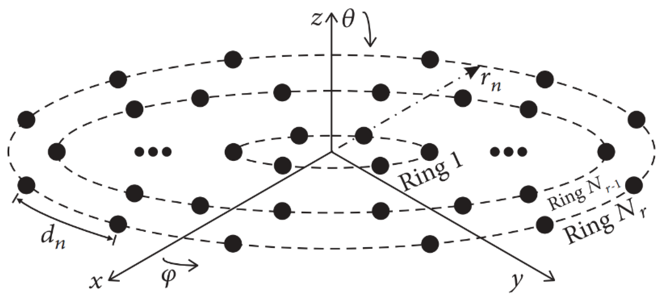
Among the possible planar array configurations, the concentric ring array exhibits the interesting properties of a nearly invariant pattern for a full azimuthal coverage and main beam symmetry [12]. The array factor for this geometry can be determined using the array factor expression for a planar antenna array. The concentric ring array consists of Nr rings and Ne antenna elements in each ring on the x-y plane, as shown in Figure 1. The array factor of this geometry can be determined using the next expression [15]:
where u = sinθcosϕ, v = sinθsinϕ, k = 2π/λ is the phase constant with λ representing the operating wavelength, θ is the angle of a plane wave in the elevation plane and ϕ is the angle of a plane wave in the azimuth plane. In this case, the position of each antenna element is defined by (xnm = rncosφnm, ynm = rnsinφnm), where rn represents the radial distance of each ring from the common center of the array until the nth ring. The antenna element distribution for the case of (UW-ACRArings) is given in each circular ring by φnm = 2π(m − 1)/Ne. This design case of concentric ring array does not consider a central element in the origin.
The array factor as a function of the non-uniform inter-element spacing in each ring and the different radius of each ring, that is, the UW-ACRAelements case [11,16,17,18], can be determined using the next expression:
where d = [d1,1, d1,2, …, d1,N1; d2,1, d2,2,…, d2,N2; …; dNr,1, dNr,2,…, dNr,Ne] dnm represents the arc longitude from element m to element m + 1 on the nth ring of the array. The radii of the antenna array are grouped in r = [r1, r2, …, rn, …, rNr]. Equation (2) is a function of the product of the radius and the phase constant, i.e., krn = 2πrn/λ. This gives the perimeter of each ring (in terms of λ) which can be calculated as the sum of all arc longitudes or separations between antenna elements, so, krn = 2πrn/λ =. The notation in dm (λ) denotes that the separations between antenna elements are in terms of wavelength.
The frequency range is specified by using the fractional bandwidth (FBW) defined as [13]:
where fM, fU and fL are respectively the center, the upper and the lower frequency. According to (3), arrays are considered wideband when 0.2 < FBW < 0.5 and ultrawideband when FBW > 0.5 [13].
This design problem of an ultra-wideband antenna array consists of minimizing the peak sidelobe level (PSLL) of the array factor AF(θ,ϕ,d,r) [2]:
while enforcing a minimum element spacing (dmin), i.e., with respect to a minimum element spacing generated (dgenerated) by the concentric ring structure
which determines the bandwidth of the concentric ring array. Element spacing is typically constrained to 0.5λ at the lowest operating frequency of the array to avoid overlapping elements and undesirably large mutual coupling [2]. For arrays able to operate effectively with no grating lobes and low side lobes at a minimum element spacing of bλ (where b ≥ 0.5), the resulting frequency bandwidth is then 2b:1 [2]. Therefore, the design problem can be set as the minimization of the next objective function (OF):
2.2. Optimization Procedure
The optimization procedure is carried out by Differential Evolution due to its effectiveness solving antenna array designs [19,20,21,22,23]. The flowchart for the DE optimization procedure is shown in Figure 2 [24]. The initial population is randomly generated. Each member (or potential solution) of the population is represented by for . Then, for each generated vector a mutation vector (vi,G+1) is calculated in according to [14]:
The indexes are different among them ( and also different from index i. PopSize is the size of the population. F is a real parameter , which controls the amplification on the differential variation .
Once the stage of mutation is finished, the mutation vector undergoes for crossover operation. The trial vector is performed in according to [13]:
In (8), , is a random number , is the crossover ratio, is randomly chosen index (D is the dimension of the problem) which ensures that gets at least one parameter from .
Each solution vector is codified by the values of spacing between rings and the values of spacing between the elements on the nth ring. The fitness evaluation for the array factor of each solution vector must follow the considerations given for Equation (6).
To decide whether the trial vector should be selected for the next generation or not, is compared to the target vector by greedy criterion. If the trial vector has got smaller fitness value than , then is set to ; otherwise, the old value of is retained. This procedure is repeated over and over until the algorithm reaches the maximum number of generations G. Detailed information of the DE optimization procedure can be found in [14].
3. Simulation Results
The method of DE was implemented in Matlab following the methodology described in [12]. Four array configurations are considered for both design cases: 1) NT = 90 antenna elements distributed in Nr = 5 rings, 2) NT = 126 with Nr = 6, 3) NT = 168 with Nr = 7 and 4) NT = 216 with Nr = 8, for N1 = 6, N2 = 12, N3 = 18, N4 = 24, N5 = 30, N6 = 36, N7 = 42 and N8 = 48. The ultra-wideband characteristics of these aperiodic concentric ring antenna arrays have been analyzed, focusing on PSLL performance at minimum element spacing ranging from 0.5λ to 10λ. This minimum spacing range corresponds to operating frequencies of f0 to 20f0, with f0 designated as the lowest operating frequency of the array.
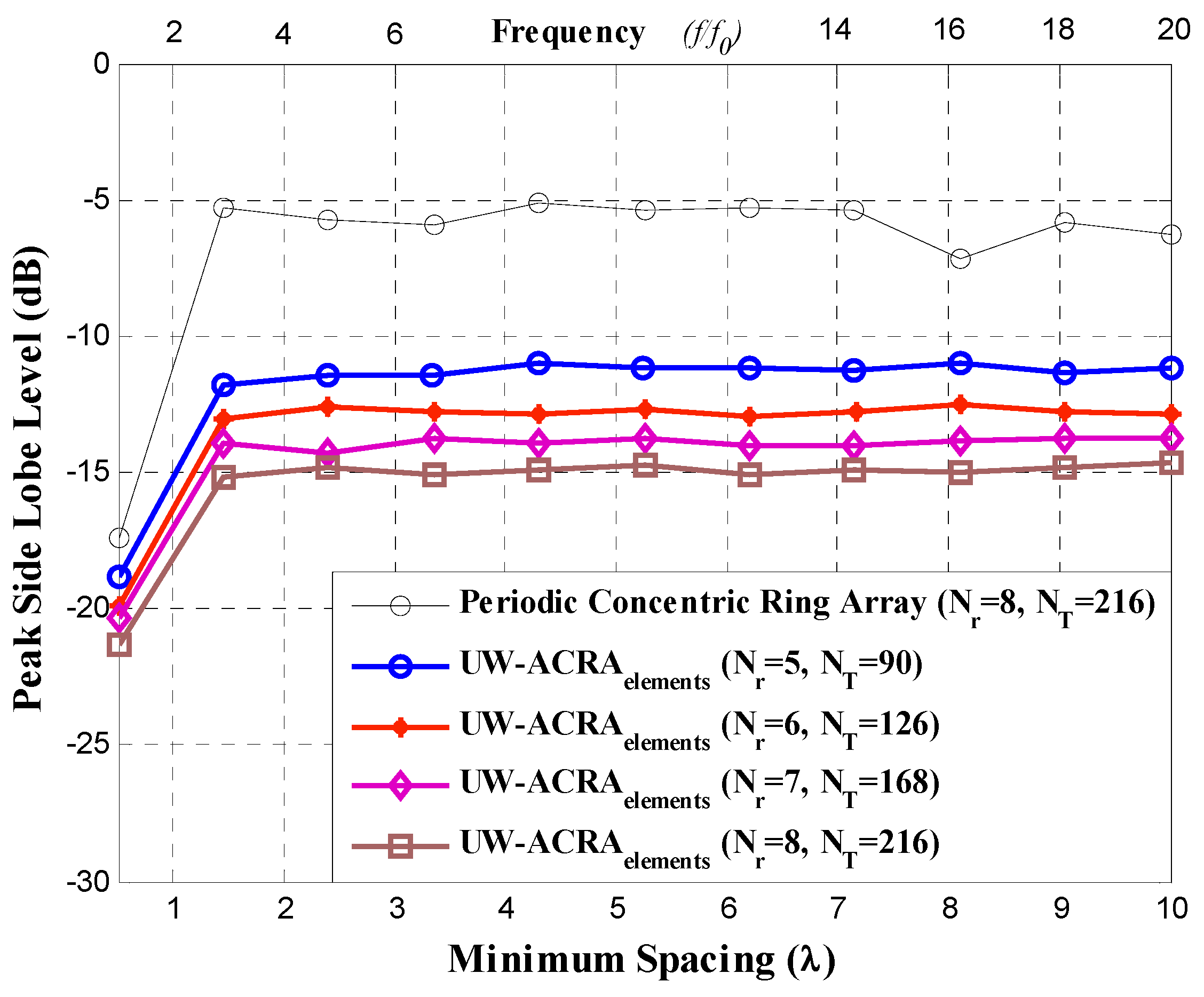
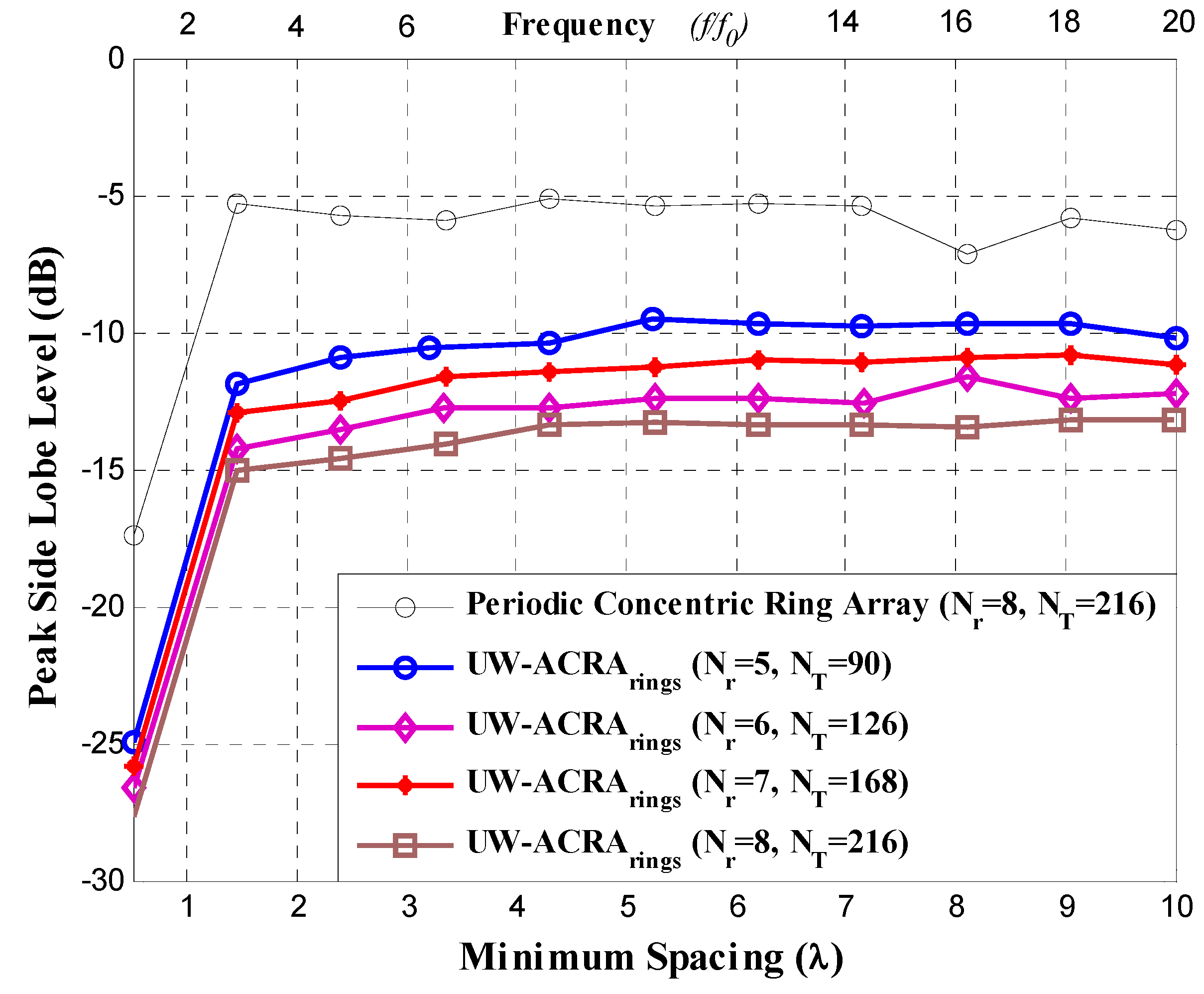
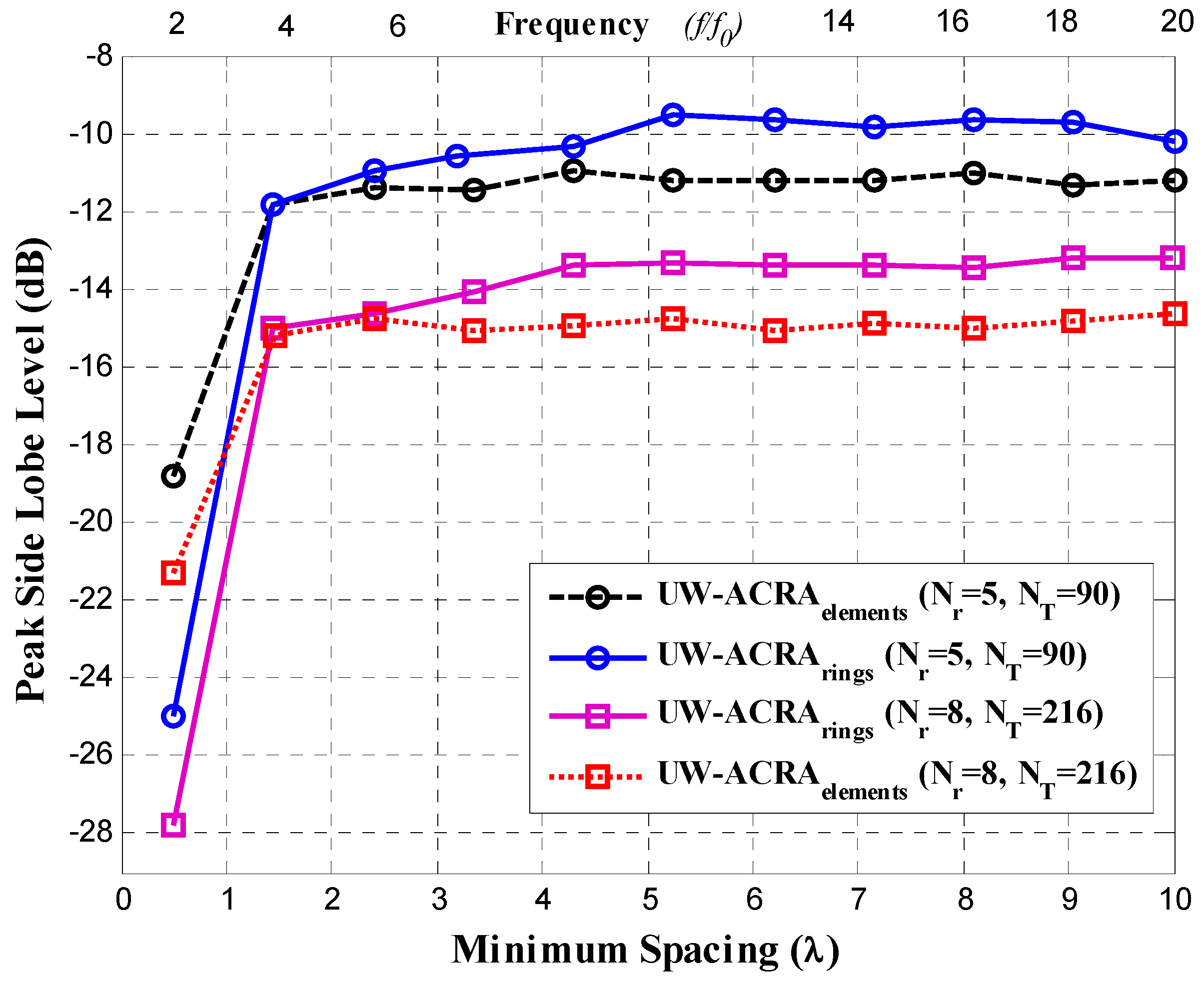
Figure 3 and Figure 4 illustrate the PSLL performance of the non-uniform concentric ring arrays optimized by DE for the case of UW-ACRAelements and UW-ACRArings, respectively. The optimization of both geometries provides low values of PSLL for the element spacing corresponding to frequencies of f0 to 20f0. The behavior of the periodic concentric ring array is determined using NT = 216 antenna elements with Nr = 8 rings. Both aperiodic geometries present a better PSLL performance with respect to the periodic case. The lowest values of PSLL (in each design case) are found for dmin = 0.5λ with lower values for UW-ACRArings (ranging from −24.95 dB to −27.82 dB) with respect to UW-ACRAelements (from −18.84 dB to −21.30 dB). If the minimum spacing is increased (operating frequencies greater than 3f0) the PSLL performance deteriorates for periodic case, and the case of UW-ACRAelements presents better PSLL values with respect to UW-ACRArings, as shown in Figure 5. The minimum and maximum values of PSLL found by the case of UW-ACRAelements and UW-ACRArings are PSLLmax = −10.96 dB, PSLLmin = −15.92, and PSLLmax = −9.55 dB and PSLLmin = −15.01, respectively, for the element spacing corresponding to operating frequencies greater than 3f0. Furthermore, the case of UW-ACRAelements covers totally the UW-ACRArings for frequency values greater than 5f0 reaching the maximum difference in dmin = 5.25λ for NT = 90 and Nr = 5 and 6.2λ for NT = 216 and Nr = 8. The resolution of minimum spacing in the performance evaluation of Figure 3, Figure 4 and Figure 5 is approximately one wavelength. The response in the performance of the concentric ring array could be improved by increasing the resolution of the minimum spacing in the optimization procedure. This would require more intensive simulations and computational cost. However, the response illustrated in these Figures provide enough information to make a fair comparison among the design cases.
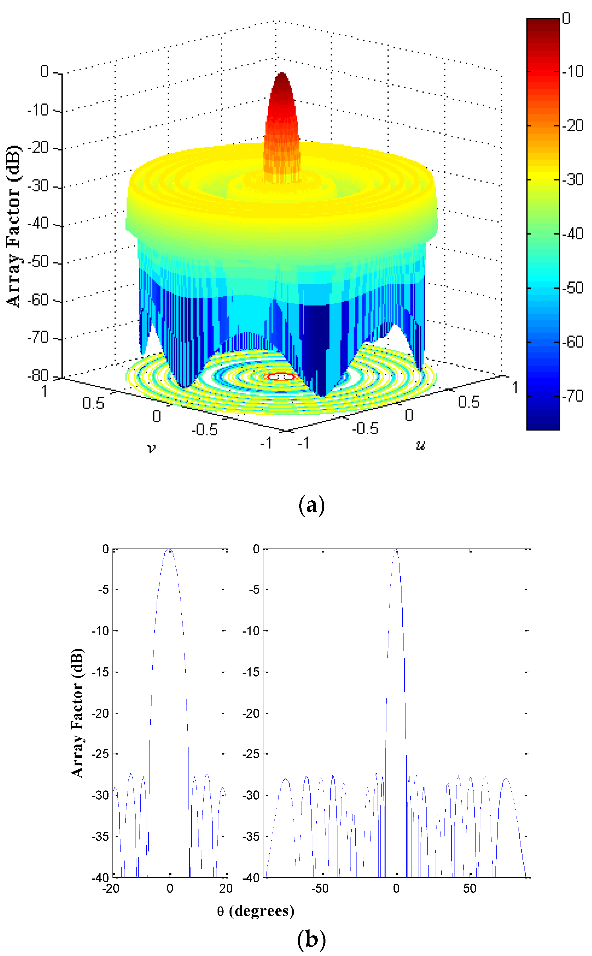
The geometry of the non-uniform concentric rings array for the design case UW-ACRArings of NT = 216 with Nr = 8 rings at a frequency f = f0 (minimum element spacing of 0.5λ) is shown in Figure 6. The array factor and a cut of the array factor at ϕ = 0° for this antenna array configuration is demonstrated in Figure 7.
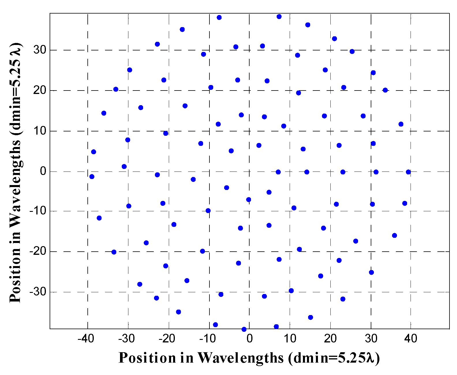
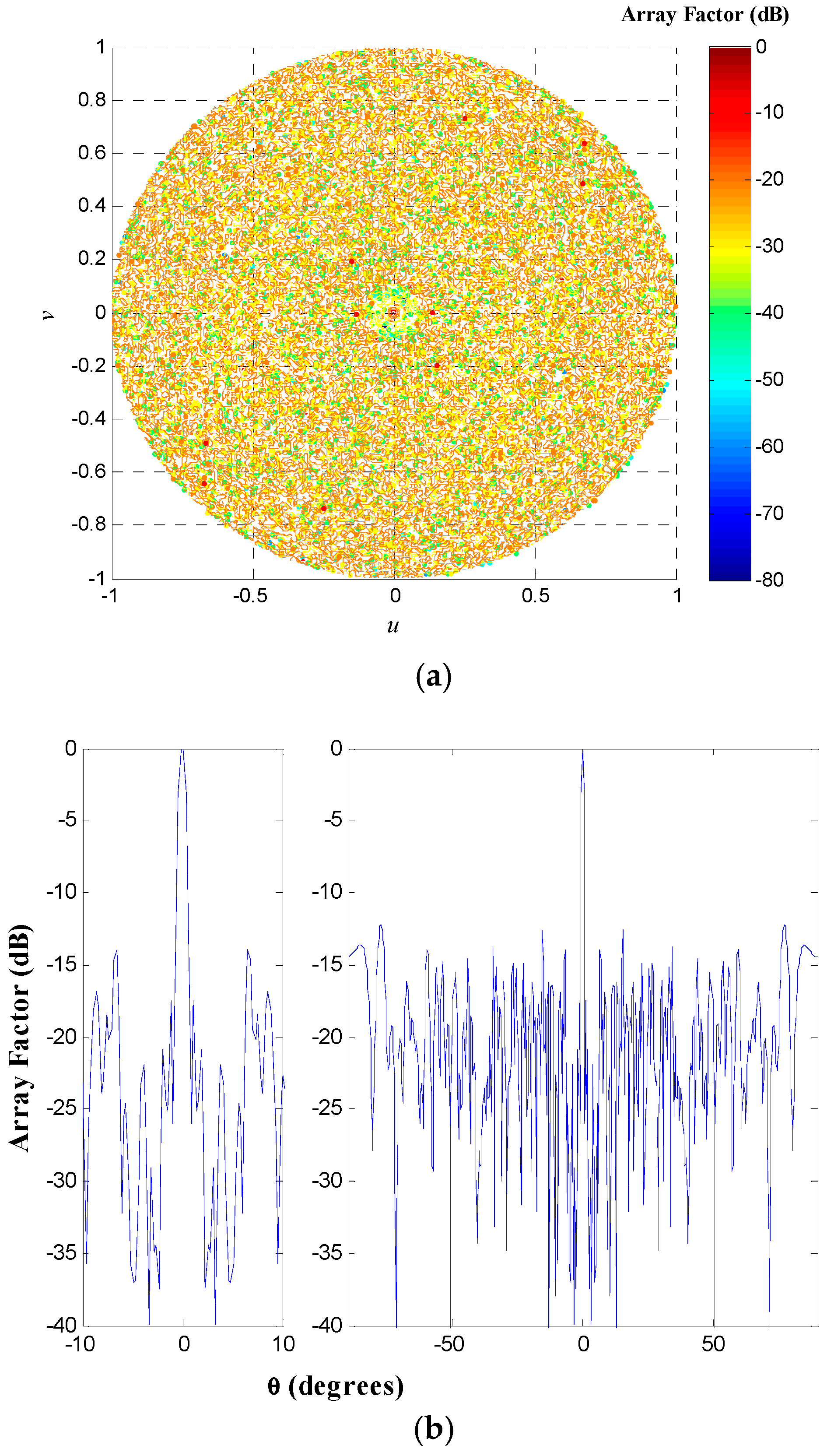
Furthermore, the antenna array configuration of the design case UW-ACRAelements of NT = 90 antenna elements with Nr = 5 rings at a frequency f = 10.5f0 (corresponding to a minimum element spacing of 5.25λ) is shown in Figure 8. The array factor and a cut of the array factor at ϕ = 0° for this antenna array configuration is demonstrated in Figure 9.
Table 1 illustrates a performance summary of the design cases UW-ACRAelements and UW-ACRArings, and a comparative analysis in PSLL performance at a frequency f = f0 (dmin = 0.5λ) and f = 20f0 (dmin = 10λ) with respect to previous works in the literature. As shown in Table 1, the design case UW-ACRArings outperforms all design cases when a dmin = 0.5λ is set in the array configuration. For high bandwidth ratios the design cases UW-ACRArings and UW-ACRAelements yield a good design trade-off between the number of elements and the PSLL performance. In this case, UW-ACRAelements presents the best compromise between the number of antenna elements and PSLL performance for a dmin = 10λ.
This paper only considers two design objectives: SLL and minimum element spacing (bandwidth). This is because the non-uniform arrays may offer a wider range of frequencies but suffer from a limited ability to predictably control the worst case of peak SLL. More design objectives could be considered in the cost function. In that case multi-objective optimization algorithms could be more efficient to search for a Pareto approximation among all the objectives, but that could be the subject of another research manuscript. Furthermore, the results obtained could be integrated with the results of this paper.
4. Conclusions
The simulation results demonstrated that for the antenna array configurations of aperiodic concentric rings, the method of DE found the element spacing to provide low PSLL over an extended bandwidth for the element spacing corresponding to frequencies of f0 to 20f0. Both aperiodic geometries present a better PSLL performance with respect to the periodic case. The lowest values of PSLL (in each design case) are found for dmin = 0.5λ with lower values for UW-ACRArings with respect to UW-ACRAelements.
For high bandwidth ratios, the design cases UW-ACRArings and UW-ACRAelements yield a good design trade-off between the number of elements and the PSLL performance. However, the design case UW-ACRAelements presents the best compromise between the number of antenna elements and PSLL performance for frequency values greater than 5f0.
Future studies could investigate the application of multi-objective optimization algorithms to search for a Pareto approximation among all the design objectives. Furthermore, the application of these multi-objective optimization techniques could be extended to other antenna array geometries.
Author Contributions
Conceptualization, M.A.P.; methodology, M.A.P. and A.R.; software, A.R. and D.H.C.; validation, M.A.P., A.R. and D.H.C.; investigation, M.A.P. and A.R.; writing—original draft preparation, M.A.P.; writing—review and editing, A.R. and D.H.C.; project administration, M.A.P. and D.H.C.
Funding
This paper has been supported by the Mexican Council for Science and Technology (CONACyT), under Grant no. 2016-01-1680.
Conflicts of Interest
The authors declare no conflict of interest.
References
- Huang, R.; Manoli, Y. Phased array and adaptive antenna transceivers in wireless sensor networks. In Proceedings of the Euromicro Symposium on Digital System Design, Rennes, France, 31 August–3 September 2004; pp. 587–592. [Google Scholar]
- Gregory, D.M.; Werner, D.H. Exploiting rotational symmetry for the design of ultra-wideband planar phased array layouts. IEEE Trans. Antennas Propag. 2013, 61, 176–184. [Google Scholar] [CrossRef]
- Petko, J.S.; Werner, D.H. The evolution of optimal linear polyfractal arrays using genetic algorithms. IEEE Trans. Antennas Propag. 2005, 53, 3604–3615. [Google Scholar] [CrossRef]
- Gorman, J.P.; Werner, D.H. Design of ultra-wideband, aperiodic antenna arrays with the CMA evolutionary strategy. IEEE Trans. Antennas Propag. 2014, 62, 1663–1672. [Google Scholar] [CrossRef]
- Agrawal, V.; Lo, Y. Mutual coupling in phased arrays of randomly spaced antenas. IEEE Trans. Antennas Propag. 1972, 20, 288–295. [Google Scholar] [CrossRef]
- Petko, J.S.; Werner, D.H. The pareto optimization of ultrawideband polyfractal arrays. IEEE Trans. Antennas Propag. 2008, 56, 97–107. [Google Scholar] [CrossRef]
- Gregory, M.D.; Werner, D.H. Ultrawideband aperiodic antenna arrays based on optimized raised power series representations. IEEE Trans. Antennas Propag. 2010, 58, 756–764. [Google Scholar] [CrossRef]
- Spence, T.G.; Werner, D.H. Design of broadband planar arrays based on the optimization of aperiodic tilings. IEEE Trans. Antenna. Propag. 2008, 56, 76–86. [Google Scholar] [CrossRef]
- Panduro, A.M.; Méndez, A.; Dominiguey-Cruz, R.; Romero, G. Design of non-uniform circular antenna arrays for side lobe reduction using the method of genetic algorithms. Int. J. Electron. Commun. AEUE 2006, 60, 713–717. [Google Scholar] [CrossRef]
- Stearns, C.O.; Stewart, A.C. An investigation of concentric ring antennas with low sidelobes. IEEE Trans. Antennas Propag. 1965, 18, 856–863. [Google Scholar] [CrossRef]
- Haupt, R.L. Optimized element spacing for low sidelobe concentric ring arrays. IEEE Transact. Antennas Propag. 2008, 56, 266–268. [Google Scholar] [CrossRef]
- Bianchi, D.; Genovesi, S.; A Monorchio, A. Constrained pareto optimization of wide band and steerable concentric ring arrays. IEEE Transact. Antennas Propag. 2012, 60, 3195–3204. [Google Scholar] [CrossRef]
- Bevelacqua, P.J.; Balanis, C. Geometry and weight optimization for minimizing sidelobes in wideband planar arrays. IEEE Transact. Antennas Propag. 2009, 57, 1285–1289. [Google Scholar] [CrossRef]
- Price, K.V.; Storn, R.M.; Lampinen, J.A. Differential Evolution: A Practical Approach to Global; Springer: Berlin, Germany, 2004. [Google Scholar]
- Balanis, C.A. Antenna Theory: Analysis and Design; John Wiley & Sons: Hoboken, NJ, USA, 2016. [Google Scholar]
- Zhang, L.; Yong-Chao, J.; Chen, B. Optimization of concentric ring array geometry for 3D beam scanning. Int. J. Antennas Propag. 2012, 2012, 625437. [Google Scholar] [CrossRef]
- Bencivenni, C.; Ivashina, M.; Maaskant, R. Reconfigurable aperiodic array synthesis by compressive sensing. In Proceedings of the 10th European Conference on Antennas and Propagation (EUCAP), Davos, Switzerland, 10–15 April 2016; pp. 1–3. [Google Scholar]
- Salas-Sanchez, A.A.; Fondevila-Gomez, J.; Rodriguez-Gonzalez, J.A.; Ares-Pena, F.J. Parametric synthesis of well-scanning isophoric pencil beams. IEEE Trans. Antennas Propag. 2017, 65, 1422–1427. [Google Scholar] [CrossRef]
- Subhashini, K.R.; Baranwal, A.; Kumar, A.P.; Reddy, M.S. Co sequent shaped Pattern Synthesis in Spherical Antenna Array with Excitation Optimization using Clever Algorithms. In Proceedings of the 2014 Annual IEEE India Conference (INDICON), Pune, India, 11–13 December 2014. [Google Scholar]
- Kumar, A.T.; Praven, K.R.; Subhasini, K.R. Non Uniform Element Angular Spacing of a Hemi Spherical Antenna Array for Vector Optimization Employing Natural Computing Techniques. In Proceedings of the 2013 Annual IEEE India Conference (INDICON), Pune, India, 13–15 December 2013. [Google Scholar]
- Rocha-Alicano, C.; Covarrubias-Rosales, D.; Brizuela-Rodriguez, C.; Panduro-Mendoza, M. Differential Evolution Algorithm Applied to Sidelobe Level Reduction on a Planar Array. AEU Int. J. Electromagn. Commun. 2007, 61, 286–290. [Google Scholar] [CrossRef]
- Elizarraras, O.; Mendez, A.; Reyna, A.; Panduro, M.A. Design of Spherical Antenna Arrays for a 3D Scannable Pattern using Differential Evolution. In Proceedings of the 2016 Loughborough Antennas and Propagation Conference (LAPC), Leicestershire, UK, 14–15 November 2016. [Google Scholar]
- Elizarraras, O.; Panduro, M.A.; Mendez, A.; Reyna, A.; Covarubias, D.H. Design of Circular Antennas Arrays of Circular Subarrays Exploting Rotational Symmetry. J. Electromagn. Waves Appl. 2017, 31, 1277–1288. [Google Scholar] [CrossRef]
- Medina, Z.; Reyna, A.; Panduro, M.A.; Elizarraras, O. Dual-Band Performance Evaluation of Time-Modulated Circular Geometry Array With Microstrip-Fed Slot Antennas. IEEE Access 2019, 7, 28625–28634. [Google Scholar] [CrossRef]
Figure 1.
Non-uniform concentric ring array.

Figure 2.
Flowchart of the differential evolution (DE) optimization applied [24].
Figure 2.
Flowchart of the differential evolution (DE) optimization applied [24].

Figure 3.
Peak sidelobe level (PSLL) performance of the aperiodic concentric rings array (UW-ACRAelements).
Figure 3.
Peak sidelobe level (PSLL) performance of the aperiodic concentric rings array (UW-ACRAelements).

Figure 4.
PSLL performance of the aperiodic concentric rings array (UW-ACRArings).

Figure 5.
Comparison of the PSLL performance between the case of UW-ACRAelements and the case UW-ACRArings.
Figure 5.
Comparison of the PSLL performance between the case of UW-ACRAelements and the case UW-ACRArings.

Figure 6.
Antenna array configuration of the design case UW-ACRArings of NT = 216 antenna elements with Nr = 8 rings at a frequency f = f0, corresponding to a minimum element spacing of 0.5λ.
Figure 6.
Antenna array configuration of the design case UW-ACRArings of NT = 216 antenna elements with Nr = 8 rings at a frequency f = f0, corresponding to a minimum element spacing of 0.5λ.

Figure 7.
(a) Array factor and (b) cut of the array factor at ϕ = 0° for the antenna array configuration illustrated in Figure 6.
Figure 7.
(a) Array factor and (b) cut of the array factor at ϕ = 0° for the antenna array configuration illustrated in Figure 6.

Figure 8.
Antenna array configuration of the design case of UW-ACRAelements of NT = 90 antenna elements with Nr = 5 rings at a frequency f = 10.5f0, corresponding to a minimum element spacing of 5.25λ.
Figure 8.
Antenna array configuration of the design case of UW-ACRAelements of NT = 90 antenna elements with Nr = 5 rings at a frequency f = 10.5f0, corresponding to a minimum element spacing of 5.25λ.

Figure 9.
(a) Array factor and (b) cut of the array factor at ϕ = 0° for the antenna array configuration illustrated in Figure 8.
Figure 9.
(a) Array factor and (b) cut of the array factor at ϕ = 0° for the antenna array configuration illustrated in Figure 8.


Table 1.
Performance summary of the design cases UW-ACRAelements and UW-ACRArings and a comparison with respect to previous works.
Table 1.
Performance summary of the design cases UW-ACRAelements and UW-ACRArings and a comparison with respect to previous works.
| Array Configuration | Number of Elements | PSLL (dB) dmin = 0.5λ | PSLL (dB) dmin = 10λ |
|---|---|---|---|
| Planar array (rotational symmetry) [2] | 220 | −16.91 | −12.05 |
| Planar array (rotational symmetry) [2] | 600 | −19.2 | −16.50 |
| Aperiodic tiling–Penrose optimized [8] | 551 | −16.49 | −6.50 |
| Aperiodic tiling–Danzer optimized [8] | 811 | −16.01 | −10.73 |
| UW-ACRArings | 90 | −24.95 | −10.21 |
| UW-ACRArings | 126 | −25.87 | −11.16 |
| UW-ACRArings | 168 | −26.59 | −12.24 |
| UW-ACRArings | 216 | −27.82 | −13.22 |
| UW-ACRAelements | 90 | −18.84 | −11.20 |
| UW-ACRAelements | 126 | −19.91 | −12.83 |
| UW-ACRAelements | 168 | −20.35 | −13.76 |
| UW-ACRAelements | 216 | −21.30 | −14.66 |
| Periodic Concentric Ring | 216 | −17.37 | −6.30 |
© 2019 by the authors. Licensee MDPI, Basel, Switzerland. This article is an open access article distributed under the terms and conditions of the Creative Commons Attribution (CC BY) license (http://creativecommons.org/licenses/by/4.0/).
Share and Cite
MDPI and ACS Style
Panduro, M.A.; Reyna, A.; Covarrubias, D.H. Non-Uniform Concentric Rings Design for Ultra-Wideband Arrays. Sensors 2019, 19, 2262. https://doi.org/10.3390/s19102262
AMA Style
Panduro MA, Reyna A, Covarrubias DH. Non-Uniform Concentric Rings Design for Ultra-Wideband Arrays. Sensors. 2019; 19(10):2262. https://doi.org/10.3390/s19102262
Chicago/Turabian StylePanduro, Marco A., Alberto Reyna, and David H. Covarrubias. 2019. "Non-Uniform Concentric Rings Design for Ultra-Wideband Arrays" Sensors 19, no. 10: 2262. https://doi.org/10.3390/s19102262
Note that from the first issue of 2016, this journal uses article numbers instead of page numbers. See further details here.