Sensor Fault Detection and System Reconfiguration for DC-DC Boost Converter

School of Automation Engineering, Northeast Electric Power University, Jilin 132012, China
*
Author to whom correspondence should be addressed.
Sensors 2018, 18(5), 1375; https://doi.org/10.3390/s18051375
Submission received: 27 March 2018
/
Revised: 20 April 2018
/
Accepted: 24 April 2018
/
Published: 28 April 2018
(This article belongs to the Special Issue Sensors for Fault Detection)
Abstract
:This paper presents a effective sensor fault detection and system reconfiguration approach for DC-DC Boost converter. We consider to design a Luenberger observer to solve the problem of the sensor fault detection of the DC-DC Boost converter. We establish mathematical model according to the state of the switch . Luenberger observer is designed to produce residual errors and analyse faults. We detect three types of sensor faults online and compare residuals with thresholds. The system is able to maintain stability by taking system reconfiguration approach. The effectiveness of this approach is demonstrated by simulations.
1. Introduction
In recent decades, sensor fault detection in power electronics has aroused increasing attention. Power electronics products, such as switching power supply, frequency converter and UPS power supply, have been widely used in all aspects of social life and national economy such as aerospace, automobile system, vehicle system, ship system, medical equipment and so on [1,2]. The safe operation of power electronic products is of great significance to the safety, efficiency and quality of the entire system.
According to the power conversion type of the power treatment device, The switching converters have the following four basic forms:AC-DC converters, AC-AC converters, DC-AC converters, DC-DC converters. Thereinto, DC-DC converters have widely applied to many fields, including multiple input source applications [3], offshore wind power [4] and so on. To achieve an ultrahigh step-up ratio while maintaining a high conversion efficiency, a novel DC-DC converter topology is proposed in [5]. The design and control of DC-DC converters is an important branch of electronic technology. There are three common fault in DC-DC converters: open -circuit fault, gain deviation fault and noise abnormity fault. In this case, some solutions about fault detection and fault tolerant control methods have been proposed [6,7,8,9]. In [10], the model-based estimator approach is used to design a fault diagnosis method for switching power converters . In [11], based on analytical redundancy relations, the paper design the sensor fault detection and isolation method. It is the role of transforming the direct current of input into the direct current of output which has different characteristics. Thereinto, the DC-DC boost converter is widely used into daily life. This is a direct-current converter with an output voltage higher than the input voltage. In recent years, some papers propose different methods to research and analysis this boost converter [12,13,14,15,16,17,18]. In [19], the paper proposed a open circuit switch fault detection method which is very fast and effective with the fault tolerant converter topology.
In the field of automatic control, sensors are the main devices for information acquisition. When a sensor faults occurs, it will have a serious impact on the follow-up monitoring and controlling. Therefore, the researching of sensor fault detection is particularly important. Under these circumstances, some papers proposed different sensor fault detection methods [20,21,22,23]. In addition, there are some reconfiguration schemes for fault tolerant control [24,25,26,27] . Common sensor faults mainly include three kinds of faults: open-circuit fault, gain deviation fault and noise abnormity fault. Real-time detection of DC-DC converter fault by online and the appropriate fault-tolerant control approaches can improve the fault-tolerant ability of the system .
Many kinds of observer-based fault detection methods have been proposed which generate residuals to detect system fault information [28,29,30,31]. More recently, different kinds of observers have been used for fault detection, including Luenberger observers, adaptive observers, sliding mode observers and so on. To observe the states and estimate the component parameters , the paper designs a model-observer-based scheme for Buck converters [32]. The Luenberger observers are able to estimate current and voltage accurately. In [33], the paper design a Luenberger observer for the sensor fault detection and fault tolerant control.
This paper propose a sensor fault detection and system reconfiguration method for the DC-DC Boost converter. Firstly, the boost converter is described as a switched model, which can precisely capture the characteristics between different working modes of the converter. Secondly, a fault detection observer is designed based on the faulted mode to construct residual signal. The residual value is larger than the threshold when the sensor fault happens, an alarm is generated. Thirdly, we design a switching control law for the Boost converter under healthy condition. Then we put to use a system reconfiguration method to improve the fault-tolerant ability of the system. Finally, we apply the method proposed above to three kinds of sensor faults in the current sensor and the voltage sensor.
The structure of the paper is organized as follows. The mathematical model of the Boost converter is established in Section 2. The Luenberger observer is designed in Section 3. The switching control law for healthy condition is presented in Section 4. In Section 5, we present fault detection and system reconfiguration scheme design. In Section 6, The efficiency of this approach is demonstrated by simulation examples. Finally, we arrive at the conclusion of this paper in Section 7.
2. System Model
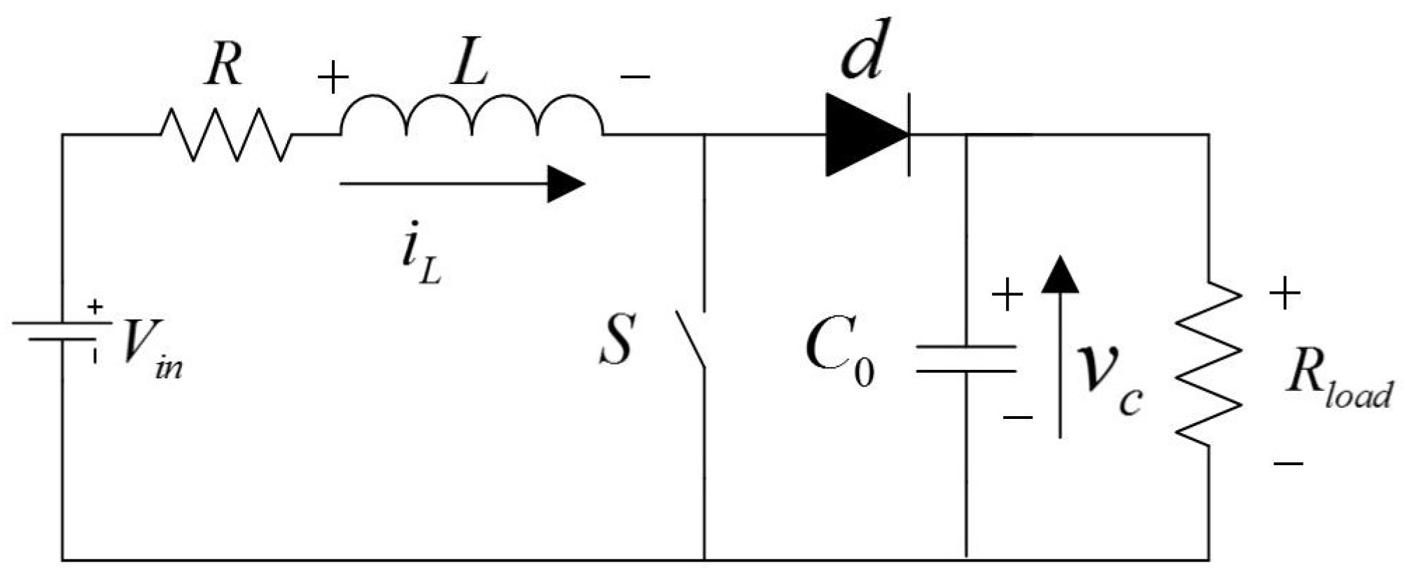
The DC-DC Boost converter circuit is shown in Figure 1. The circuit is able to get a higher voltage through the switch S . This process contains two operating modes. The switch is open (S = 0) when the system is in mode 1. The switch is closed (S = 1) in mode 2 . The two operating modes can be described as follows :
Then we can get the mathematical model of the circuit:
In the above equation, is the state vector, is the output vector, is the input vector, appears the switching signal generated by converter control. , B and C are the collection of state space models. Where , , B and C are set as:
Remark 1.
In this paper, two state vector is used to build the system model and analyse the mathematical model. Because we hope to get a stable output voltage for DC-DC boost converter. The voltage of capacitor is equal to output voltage. Therefore, we focus on the state vector .
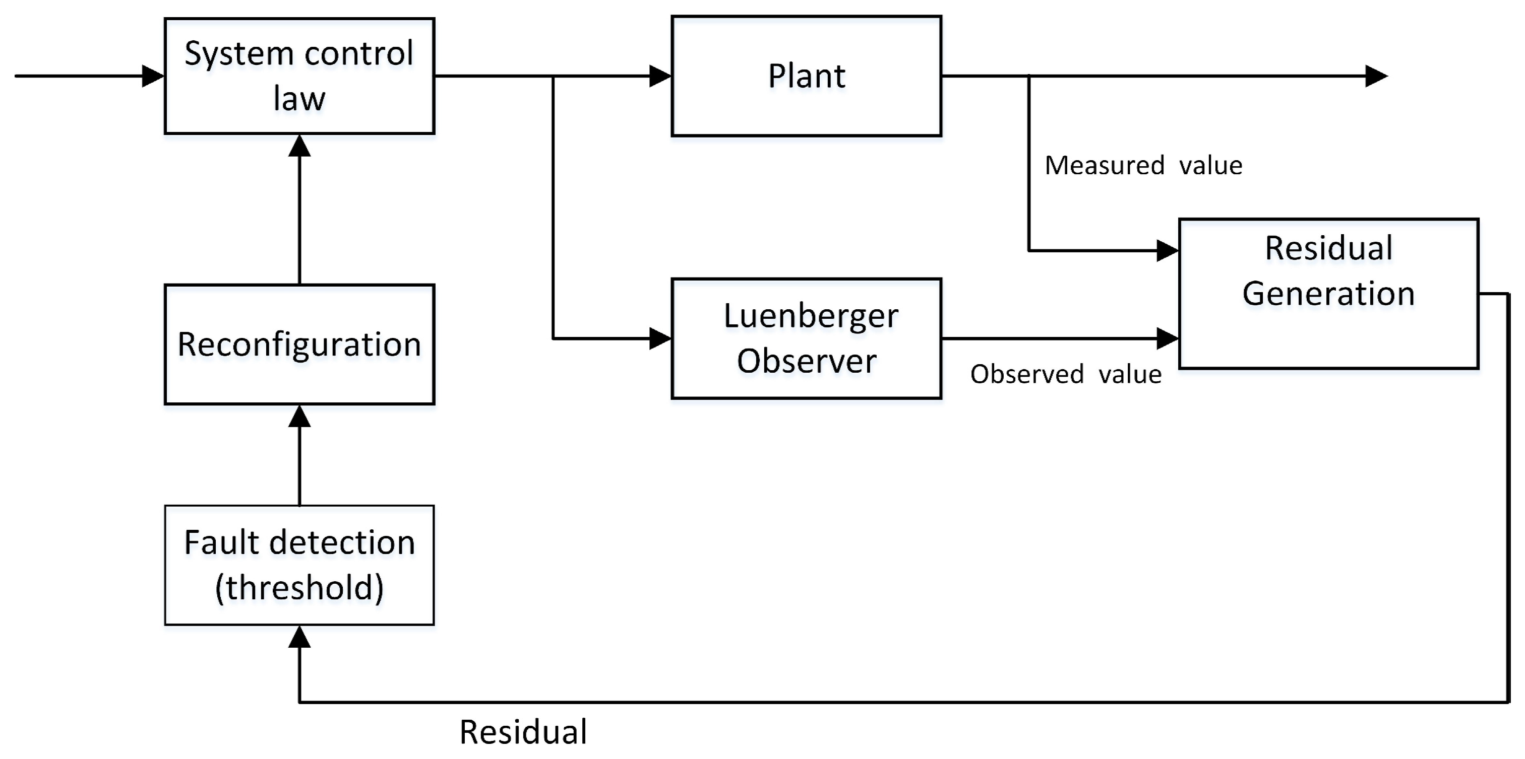
In the next sections, we need to realize the sensor fault detection and the system reconfiguration. We design a Luenberger observer to produce a residual signal and compare it with a predefined threshold. When the sensor fault happens, the residual value is larger than the threshold and an alarm is generated. Thus, the value of Luenberger observer is applied to system switching law instead of measured value. In addition, the output value y is replaced by the desired value . Consequently, The system is able to maintain stability by taking system reconfiguration approach and we can obtain a stable output voltage. The block scheme of the fault detection and system reconfiguration is shown in Figure 2.
3. Luenberger Observer Design
Since sensor faults appear in the system, the output value will have some changes. So we can describe the fault model of system as:
where with appropriate dimensions and is the sensor fault signal which caused by the undesirable sensor faults in the electric circuit. In order to realize fault detection, the following Luenberger observer for the switched system is constructed:
where is the observer state, is the observer output, H is the observer gain matrix and is the observer residual vector .
Denoting , the augmented state vector , . The augmented system of (2) and (3) can be written as
where
The frameworks of fault detection observer design: the Luenberger state-observer is designed such that the augmented system (4) is asymptotically stable when and under zero-initial condition, For detection objective, the effects from the faults to the residual error signal are minimized. The fault detection observer satisfies the following index :
In the following theorem, we obtain the necessary condition that system (4) satisfies the upper requirement. The observer gain H can be achieved at the same time.
Theorem 1.
Proof of Theorem 1.
Firstly, consider the stability for the system (4), we rewrite the system as when , and choose the common Lyapunov functions: Then it has
We consider the following performance index . For any nonzero and the under zero-initial condition, we have
It notes that
where
Thus, if , it follows form (8) that ,which implies that converges to zero as . The switched system (4) under arbitrary switching is asymptotically stable. Moreover, it also implies . Then, it has the robust performance (6).
It notes that can be rewritten as
Remark 2.
Theorem 1 has formulated the inequality conditions for the stability and the performance (6). As long as the parameters satisfy the inequalities, the system is asymptotically stable and satisfies the robust performance index (6). Moreover, it is noted that condition (7) is all convex. Hence, the problem of observer design can be directly translated into solve (7). The observer gain can be derived by .
4. System Control Law
4.1. Design of Control Law
In [34], the paper design a switching control law for the Boost converter under healthy condition. In this paper, we use this switching law to guarantee the stability of the system. In this process, we will use a Lyapunov function, see [35]. Denote , then we consider the system
where . Moreover, and are desired current and voltage. We choose the control Lyapunov function
. Since represents two modes of operation, there exist two derivatives (x) {S = 0} and (x) {S = 1}. The switching law of system (1) is designed as follows:
- (1)
- If , the system is in mode 1, in which the switch is open (S = 0).
- (2)
- If , the system is in mode 2, in which the switch is closed (S = 1).
Remark 3.
For guaranteeing the switching system (11) is asymptotically stable, we consider . For Lyapunov function , the derivative of is a negative number. So the smaller the derivative, the greater the attenuation rate of . This condition is used to derive the upper switching law. Therefore, we choose the switching law as follows:
By taking this switching control law, the switching system (11) can be stable as soon as possible and we can obtain a stable output voltage. We will prove the feasibility of this switching law in the following theorem.
Theorem 2.
Proof of Theorem 2.
For guaranteeing the stability of the system (11), we consider . There exist two derivatives (x) {S = 0} and (x) {S = 1}.
- (1)
- For S = 0, we have . Substituting the parameters , using gives
- (2)
- For S = 1, we have . Substituting the parameters , using again gives
This gives the expressions
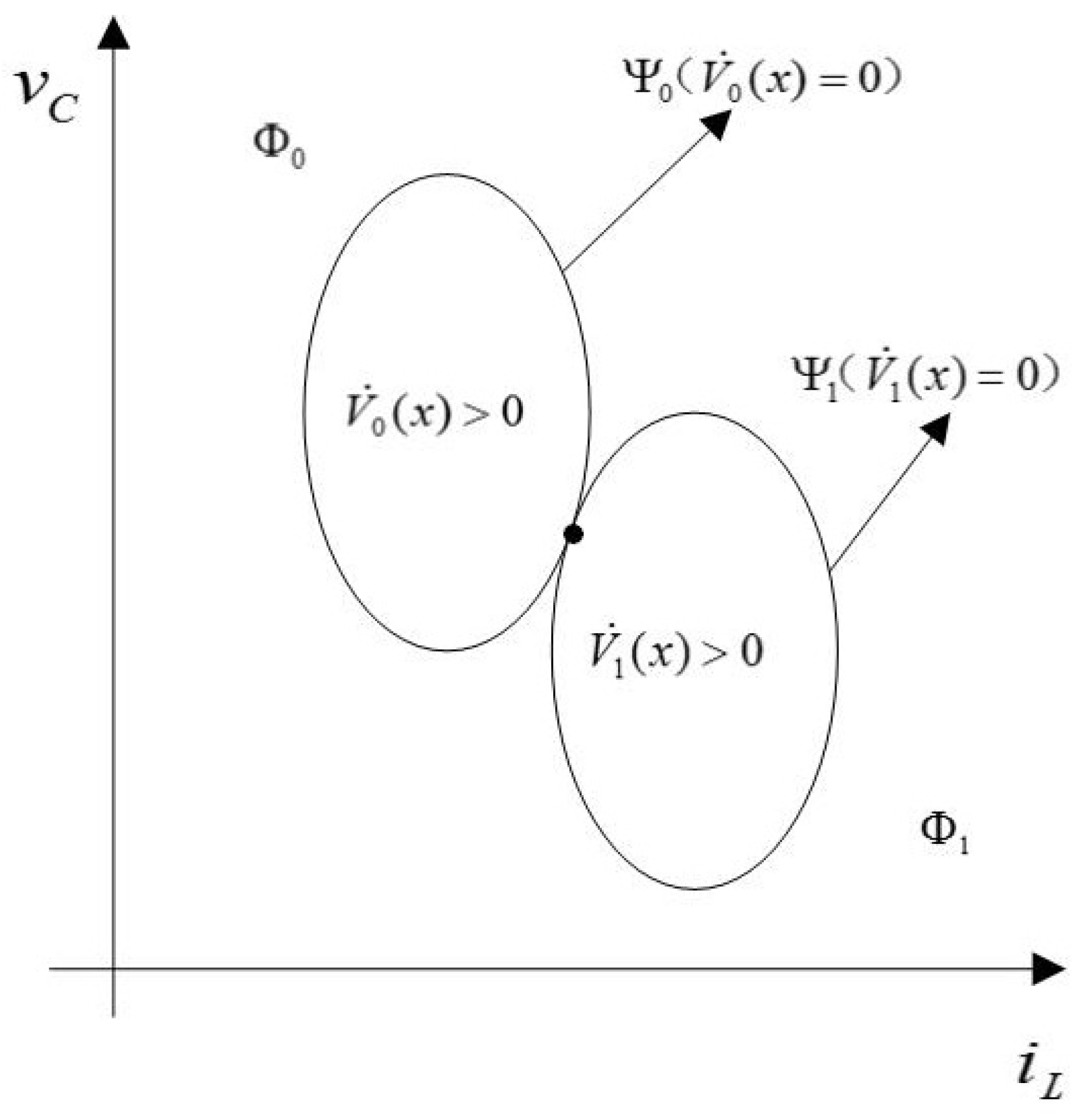
We also define :=. Obviously, and are both ellipses. Compare to , we can get the graph as in Figure 3. The graph indicates that is the external area of the ellipse . is the external area of the ellipse . For guaranteeing system (11) is asymptotically stable, for each , there exist such that . As a result, the two ellipses must have a unique crossover point at most, which leads to
we have
Moreover, we can obtain is the unique crossover point of two ellipses which is the equilibrium point of system (11). The proof of the theorem is complete. ☐
Remark 4.
actually is the intersection point of two ellipses. It is also a equilibrium point of the switching law. In order to ensure that the equilibrium point is unique, the intersection point of two ellipses is only one. Then we can get and from the process of solving Equation (19).
4.2. Separation Principle
In order to realize system reconfiguration, state value x and output value y are replaced by and . Therefore, we will discuss the feasibility of this system reconfiguration approach. Let Since it has
Calculating the poles of augmented system (21), then there
After the system reconfigured, it has
There exist and , it has
Denoting and calculating the poles
Separation principle is applied in this process. From Equations (22) and (23) , we can see that the poles of and are the same. It indicates that and are independent of each other. Thus, the designs of the Luenberger observer and the switching control law can be independent. Hence the system reconfiguration approach is feasible.
5. Fault Detection And System Reconfiguration Scheme Design
5.1. Residual Generation and Threshold Calculation
We calculate the threshold of sensor faults in this section. In this paper, we take into account observerd errors and measurement noise when calculating the threshold. We use residual evaluation function to calculate the threshold. This can minimize misdiagnosis. This paper focuses on three kinds of sensor faults in current sensor and voltage sensor, including open-circuit fault, gain deviation fault, and noise abnormity fault. In this paper, the designed Luenberger state-observer is used to detect three kinds of sensor faults.
In sensor fault detection, the measured value and observed value can produce residuals. The residual error for current of inductor and voltage of resistor are determined to be
Define the residual . In healthy mode, the residual error maintain at pretty low value.The residual increases instantly when sensor faults happen. We need to choose a threshold to guarantee the precision of fault detection and avoid misdiagnosis. This paper adopts residual evaluation function when calculating the threshold. The threshold can be chosen as
where 0 is the initial evaluation time instant and M is the evaluation time step. Once the evaluation function has been selected, we are able to determine the threshold. The threshold is selected such that . Thus, the threshold in this paper is determined as
Based on this, the occurrence of faults can be detected by comparing and according to the following logic rule:
5.2. Control System Reconfiguration
Fault detection and system reconfiguration can improve the fault-tolerant ability of system operation. By means of system reconfiguration, system can operate safely and maintain stability when sensor faults happen.
System reconfiguration contains two parts in this paper. The Luenberger state-observer operates normally when sensor fault happens. Hence, the value of Luenberger observer is applied to system switching law instead of measured value. In addition, the output value y is replaced by the desired value at the same time. Thus, fault tolerant control is realized by taking this system reconfiguration approach. This fault detection and system reconfiguration method is applied to three kinds of sensor faults in the current sensor and the voltage sensor.
6. Simulation Results
The efficiency of this approach is demonstrated by simulations in this section. The Boost converter model is built under MATLAB/Simulink. The simulations are performed using V, F, H, To better meet the performance index (6) and make get the minimum value. We give . By solving the LMI (7), and the FD observer gain matrix is shown as:
In this paper, we choose the threshold as . The three kinds of sensor faults in current sensor and voltage sensor are simulated when the system is in stable operation.
- (1)
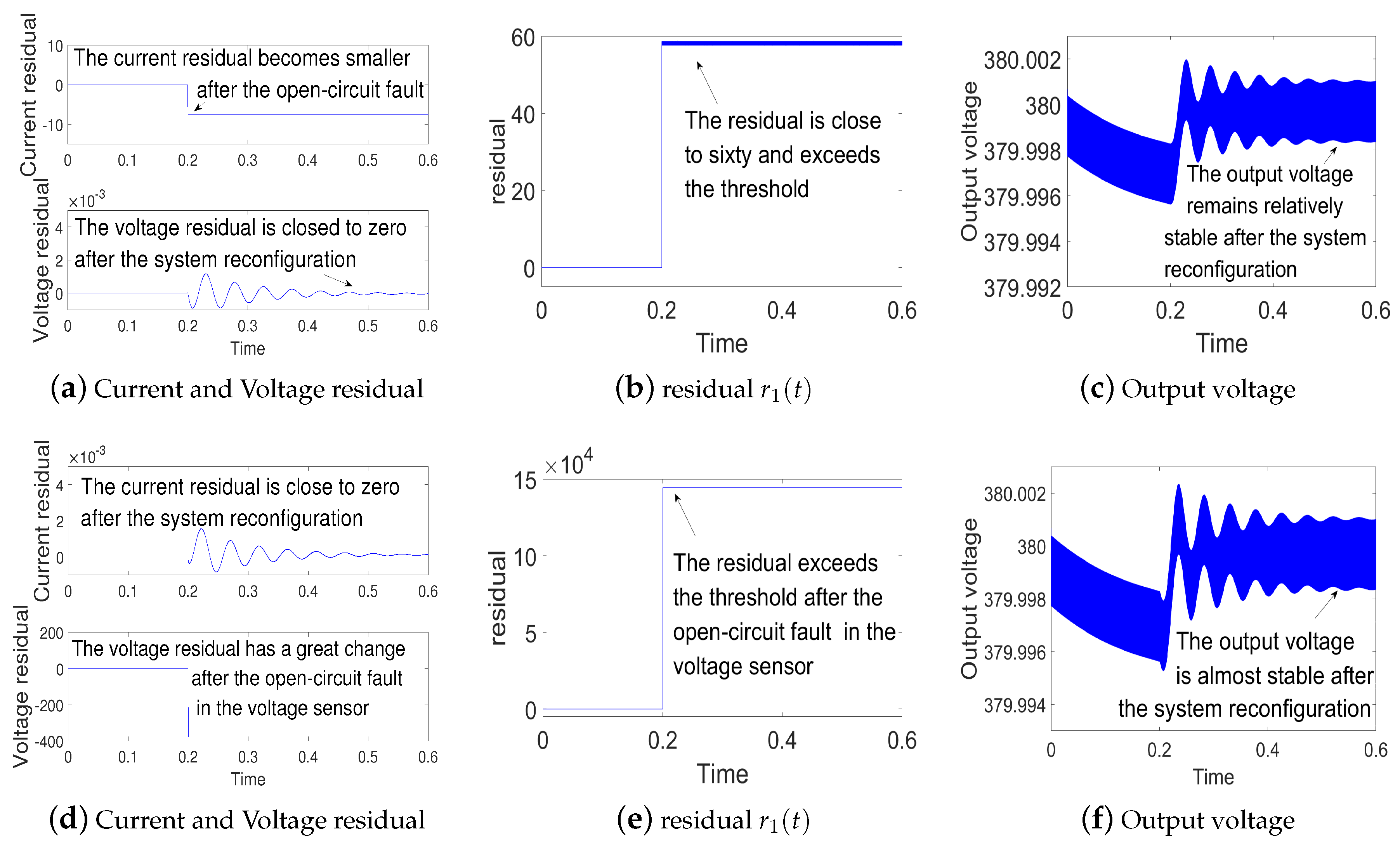
- Simulations for open-circuit fault in current sensor and voltage sensor: The simulation results for the open-circuit fault are shown in Figure 4. The state-observer still works properly when open-circuit fault occurs. Since the open-circuit fault occurs at s, the residual error is larger than the threshold. Hence the measured values are replaced by the observed values to realize system reconfiguration. According to Figure 4c,f, the output voltage remains relatively stable after the open-circuit fault. This indicates fault tolerant control is realized.
- (2)
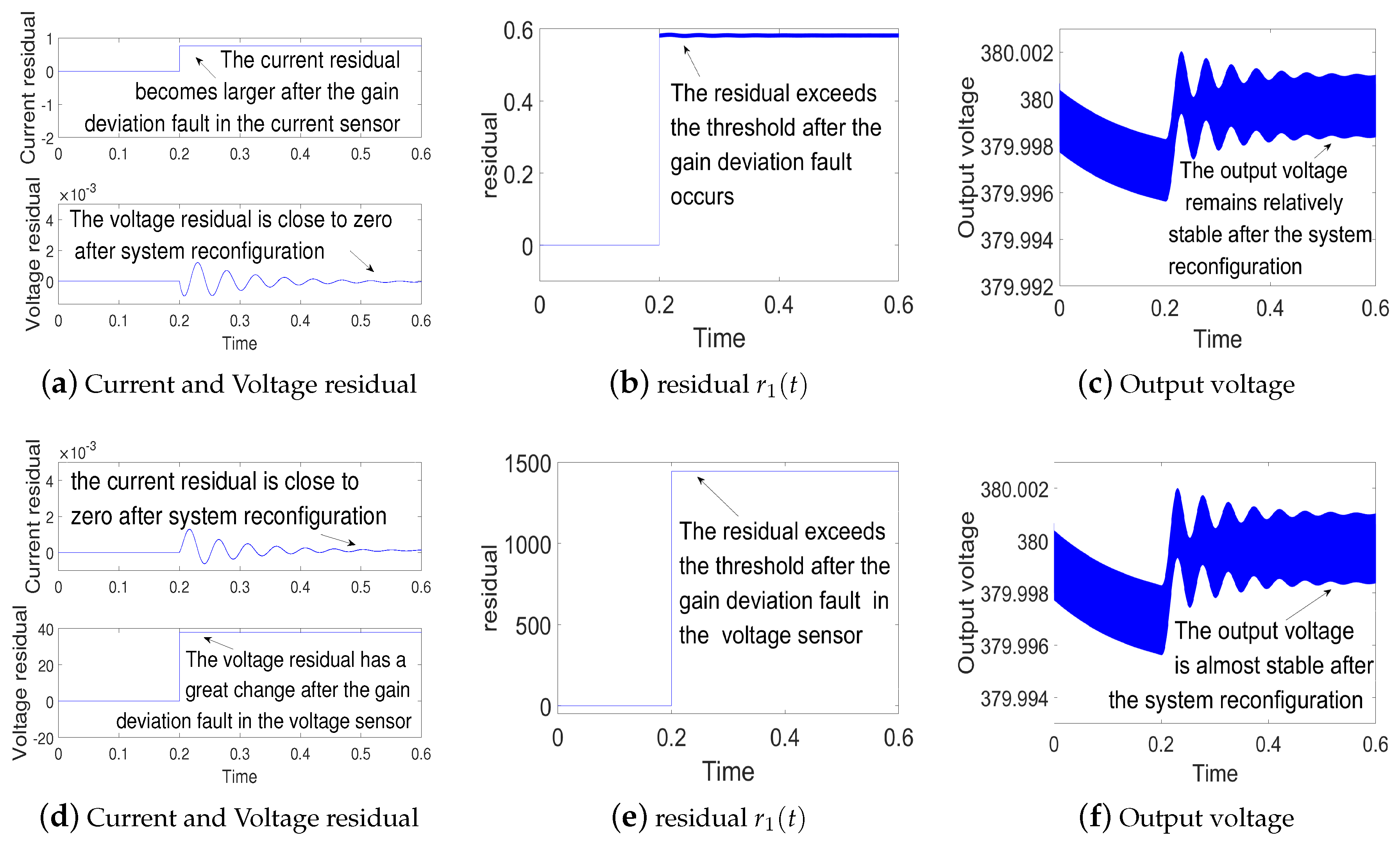
- Simulations for gain deviation fault in current sensor and voltage sensor: the gain deviation fault occurs separately in current sensor and voltage sensor at s. The simulation results are shown in Figure 5. As shown in Figure 5b,e, the residual error increases and oversteps the threshold, which indicates the current sensor fault and voltage sensor fault. Then the system is reconfigured. Finally, we can get a relatively stable output voltage.
- (3)
- Simulations for noise abnormity fault in current sensor and voltage sensor:a group of random noise is added separately on the measured values of the current and the voltage at s. The simulation results are shown in Figure 6. As Figure 6b,e suggests, the residual error keeps to zero before s. Then the residual error increases and overtakes the threshold, which indicates noise abnormity fault in current sensor and voltage sensor. By the fault tolerant control, we can get a relatively stable output voltage.
Remark 5.
The above simulation results validate the effectiveness of the proposed metnod in the Boost converter. Besides, we applied this method to converters, including Buck converters and Buck-Boost converters. In addition, the validity of the presented approach is demonstrated by simulation examples.
7. Conclusions
This fault detection and system reconfiguration method is applied to three kinds of sensor faults in the current sensor and the voltage sensor. The simulation results are shown to test and verify the effectiveness of the approach. The system is able to maintain stability by taking system reconfiguration approach. We can get a relatively stable output voltage after occurrences of sensor faults. We will build a experimental platform to verify the proposed fault detection and system reconfiguration method in the follow-up work.
Author Contributions
J.L., Z.Z. and B.L. designed the overall algorithms and the simulations. J.L., Z.Z. and B.L. performed the simulations and wrote the manuscript.
Funding
This work was supported by the National Natural Science Foundation of China (61503071, 61703091), Natural Science Foundation of Jilin Province (20180520211JH) and Science Research of Education Department of Jilin Province (201693, JJKH20170106KJ).
Acknowledgments
We are grateful to the anonymous reviewers.
Conflicts of Interest
The authors declare no conflict of interest.
Abbreviations
The following abbreviations are used in this manuscript:
| AC | Alternating current |
| DC | Direct current |
References
- Cao, J.; Emadi, A. A new battery/ultracapacitor hybrid energy storage system for electric, hybrid, and plug-in hybrid electric vehicles. IEEE Trans. Power. Electron. 2012, 27, 122–132. [Google Scholar]
- Wai, R.J.; Jhung, S.J.; Liaw, J.J.; Chang, Y.R. Intelligent optimal energy management system for hybrid power sources including fuel cell and battery. IEEE Trans. Power. Electron. 2013, 28, 3231–3244. [Google Scholar] [CrossRef]
- Li, W.; Xu, C.; Luo, H.; Hu, Y.; He, X.; Xia, C. Decoupling-Controlled Triport Composited DC-DC Converter for Multiple Energy Interface. IEEE Trans. Power Electron. 2015, 62, 4504–4513. [Google Scholar] [CrossRef]
- Hu, Y.; Zeng, R.; Cao, W.; Zhang, J.; Finney, S.J. Design of a Modular, High Step-Up Ratio DC-DC Converter for HVDC Applications Integrating Offshore Wind Power. IEEE Trans. Power Electron. 2016, 63, 2190–2202. [Google Scholar] [CrossRef]
- Hu, Y.; Wu, J.; Cao, W.; Xiao, W.; Li, P.; Finney, S.J.; Li, Y. Ultrahigh Step-Up DC-DC Converter for Distributed Generation by Three Degrees of Freedom (3DoF) Approach. IEEE Trans. Power Electron. 2016, 31, 4930–4941. [Google Scholar]
- Ribeiro, E.; Cardoso, A.J.M.; Boccaletti, C. Open-Circuit Fault Diagnosis in Interleaved DC-DC Converters. IEEE Trans. Power. Electron. 2014, 29, 3091–3102. [Google Scholar] [CrossRef]
- Saifia, D.; Chadli, M.; Labiod, S.; Karimi, H.R. H-Infinity Fuzzy Control of DC-DC Converters with Input Constraint. Math. Probl. Eng. 2012, 2012, 973082. [Google Scholar] [CrossRef]
- Ding, X.; Poon, J.; Čelanović, I. Fault Detection and Isolation Filters for Three-Phase AC-DC Power Electronics Systems. IEEE Trans. Circuit. Syst. I Regul. Pap. 2013, 60, 1038–1051. [Google Scholar] [CrossRef]
- Chibani, A.; Chadli, M.; Shi, P.; Braiek, N.B. Fuzzy Fault Detection Filter Design for T-S Fuzzy Systems in Finite Frequency Domain. IEEE Trans. Power. Electron. 2017, 25, 1051–1061. [Google Scholar] [CrossRef]
- Poon, J.; Konstantakopoulos, I.C.; Spanos, C.; Sanders, S.R. Real-Time Model-Based Fault Diagnosis for Switching Power Converters. In Proceedings of the Applied Power Electronics Conference and Exposition (APEC), Charlotte, NC, USA, 15–19 March 2015; pp. 358–364. [Google Scholar]
- Papadopoulos, P.M.; Hadjidemetriou, L.; Kyriakides, E. Robust Fault Detection, Isolation and Accommodation of Current Sensors in Grid Side Converters. IEEE Trans. Ind. Appl. 2017, 53, 2852–2861. [Google Scholar] [CrossRef]
- Vasca, F.; Iannelli, L. Advances in Industrial Control. In Dynamics and Control of Switched Electronic Systems; Springer: New York, NY, USA, 2012. [Google Scholar]
- Escobar, G.; Van Der Schaft, A.J.; Ortega, R. A hamiltonian viewpoint in the modeling of switching power converters. Automatica 1999, 35, 445–452. [Google Scholar] [CrossRef]
- Buisson, J.; Richard, P.; Cormerais, H.K. On the stabilisation of switching electrical power converters. In Hybrid Systems: Computation and Control; Springer: Berlin/Heidelberg, Germany, 2005. [Google Scholar]
- Camlibel, M.; Heemels, W.; Van Der Schaft, A.; Schumacher, J. Switched networks and complementarity. IEEE Trans. Circuits Syst. I Fundam. Theory Appl. 2003, 20, 1036–1046. [Google Scholar] [CrossRef]
- Heemels, W.; Camlibel, M.; Van Der Schaft, A.; Schumacher, J. On the dynamic analysis of piecewise linear networks. IEEE Trans. Circuits Syst. I Fundam. Theory Appl. 2002, 20, 315–327. [Google Scholar] [CrossRef]
- Frasca, R.; Camlibel, M.; Goknar, I.; Iannelli, L.; Vasca, F. Linear passive networks with ideal switches: Consistent initial conditions and state discontinuities. IEEE Trans. Circuits Syst. I Reg. Pap. 2010, 20, 3138–3151. [Google Scholar] [CrossRef] [Green Version]
- Vasca, F.; Iannelli, L.; Camlibel, M.; Frasca, R. A new perspective for modeling power electronics converters: Complementarity framework. IEEE Trans. Power Electron. 2009, 20, 3138–3151. [Google Scholar] [CrossRef]
- Jamshidpour, E.; Shahbazi, M.; Saadate, S.; Gholipour, E. FPGA Based Fault Detection and Fault Tolerance Operation in DC-DC Converters. In Proceedings of the International Symposium on Power Electronics, Electrical Drives, Automation and Motion (SPEEDAM), Ischia, Italy, 18–20 June 2014; pp. 37–42. [Google Scholar]
- Du, M.; Mhaskar, P. Isolation and handling of sensor faults in nonlinear systems. Automatica 2014, 50, 1066–1074. [Google Scholar] [CrossRef]
- Zhao, K.; Peng, L.; Zhang, C. Sliding Mode Observer-Based Current Sensor Fault Reconstruction and Unknown Load Disturbance Estimation for PMSM Driven System. Sensors 2017, 17, 2833. [Google Scholar] [CrossRef] [PubMed]
- Chang, X.; Huang, J.; Lu, F. Robust In-Flight Sensor Fault Diagnostics for Aircraft Engine Based on Sliding Mode Observers. Sensors 2017, 17, 835. [Google Scholar] [CrossRef] [PubMed]
- Xu, J.; Wang, J.; Li, S. A Method to Simultaneously Detect the Current Sensor Fault and Estimate the State of Energy for Batteries in Electric Vehicles. Sensors 2016, 16, 1328. [Google Scholar] [CrossRef] [PubMed]
- Han, J.; Zhang, H.; Wang, Y.; Zhang, K. Fault Estimation and Fault-Tolerant Control for Switched Fuzzy Stochastic Systems. IEEE Trans. Fuzzy Syst. 2018. [Google Scholar] [CrossRef]
- Aouaouda, S.; Chadli, M.; Boukhnifer, M. Robust fault tolerant tracking controller design for vehicle dynamics: A descriptor approach. Mechatronics 2015, 30, 316–326. [Google Scholar] [CrossRef]
- Jing, H.; Hu, C.; Yan, F. Robust H output-feedback control for path following of autonomous ground vehicles. Mech. Syst. Signal Proc. 2016, 70, 414–427. [Google Scholar]
- Aouaouda, S.; Chadli, M.; Boukhnifer, M. Speed sensor fault tolerant controller design for induction motor drive in EV. Neurocomputing 2016, 214, 32–43. [Google Scholar] [CrossRef]
- Scelba, G.; Donato, G.D.; Pulvirenti, M.; Capponi, F.G.; Scarcella, G. Hall-effect sensor fault detection, identification, and compensation in brushless DC drives. IEEE Trans. Ind. Appl. 2016, 50, 1542–1554. [Google Scholar]
- Huang, G.; Luo, Y.-P.; Pulvirenti, M.; Zhang, C.-F. Current Sensor Fault Diagnosis Based on a Sliding Mode Observer for PMSM Driven Systems. Sensors 2015, 15, 11027–11049. [Google Scholar] [CrossRef] [PubMed]
- Krishna, S.M.; Daya, J.L.F.; Sanjeevikumar, P. Real-Time Analysis of a Modified State Observer for Sensorless Induction Motor Drive Used in Electric Vehicle Applications. Energies 2017, 10, 1077. [Google Scholar] [CrossRef]
- Jafar, Z.; Javad, P. Sensor Fault Detection and Diagnosis of a Process Using Unknown Input Observer. Math. Comput. Appl. 2011, 16, 31–42. [Google Scholar]
- Cen, Z.; Stewart, P. Condition Parameter Estimation for Photovoltaic Buck Converters Based on Adaptive Model Observers. IEEE Trans. Reliab. 2017, 1–13. [Google Scholar] [CrossRef]
- Youssef, A.B.; Khil, S.K.E.; Belkhodja, I.S. State observer-based sensor fault detection and isolation, and fault tolerant control of a single-phase PWM rectifier for electric railway traction. IEEE Trans. Power Electron. 2013, 28, 5842–5853. [Google Scholar] [CrossRef]
- Thomas, A.F.; Chai, J.; Sanfelice, R.G. Robust Global Stabilization of the DC-DC Boost Converter via Hybrid Control. IEEE Trans. Circuit. 2017, 62, 1052–1061. [Google Scholar]
- Liberzon, D.; Trenn, S. Switched nonlinear differential algebraic equations: Solution theory, Lyapunov functions, stability. Automatica 2012, 48, 954–963. [Google Scholar] [CrossRef]
Figure 1.
Schematic representation of the DC-DC Boost converter.

Figure 2.
Block scheme of the fault detection and system reconfiguration.

Figure 3.
An example of a possible sign distribution for the two ellipses and .

Figure 4.
(a–c) are simulation results for the open-circuit fault in current sensor; (d–f) are simulation results for the open-circuit fault in voltage sensor.
Figure 4.
(a–c) are simulation results for the open-circuit fault in current sensor; (d–f) are simulation results for the open-circuit fault in voltage sensor.

Figure 5.
(a–c) are simulation results for current gain deviation fault in current sensor; (d–f) are simulation results for voltage gain deviation fault in voltage sensor.
Figure 5.
(a–c) are simulation results for current gain deviation fault in current sensor; (d–f) are simulation results for voltage gain deviation fault in voltage sensor.

Figure 6.
(a–c) are simulation results for current noise abnormity in current sensor; (d–f) are simulation results for voltage noise abnormity in voltage sensor.
Figure 6.
(a–c) are simulation results for current noise abnormity in current sensor; (d–f) are simulation results for voltage noise abnormity in voltage sensor.

© 2018 by the authors. Licensee MDPI, Basel, Switzerland. This article is an open access article distributed under the terms and conditions of the Creative Commons Attribution (CC BY) license (http://creativecommons.org/licenses/by/4.0/).
Share and Cite
MDPI and ACS Style
Li, J.; Zhang, Z.; Li, B. Sensor Fault Detection and System Reconfiguration for DC-DC Boost Converter. Sensors 2018, 18, 1375. https://doi.org/10.3390/s18051375
AMA Style
Li J, Zhang Z, Li B. Sensor Fault Detection and System Reconfiguration for DC-DC Boost Converter. Sensors. 2018; 18(5):1375. https://doi.org/10.3390/s18051375
Chicago/Turabian StyleLi, Jian, Zhigang Zhang, and Bo Li. 2018. "Sensor Fault Detection and System Reconfiguration for DC-DC Boost Converter" Sensors 18, no. 5: 1375. https://doi.org/10.3390/s18051375
Note that from the first issue of 2016, this journal uses article numbers instead of page numbers. See further details here.