Hybrid Beamforming for Reduction of Inter-Beam Interference in Millimeter-Wave Cellular Systems


School of Electrical and Electronics Engineering, Chung-Ang University, Seoul 06974, Korea
*
Author to whom correspondence should be addressed.
Sensors 2018, 18(2), 528; https://doi.org/10.3390/s18020528
Submission received: 18 November 2017
/
Revised: 2 February 2018
/
Accepted: 7 February 2018
/
Published: 9 February 2018
(This article belongs to the Section Sensor Networks)
Abstract
:In millimeter-wave (mm-wave) cellular systems, beamforming antennas are necessary at both the base station (BS) and mobile station (MS) to compensate for high attenuation in mm-wave frequency bands and to extend the transmission range. The beamforming antennas also allow each BS to serve a number of MSs simultaneously, providing a substantial gain in system capacity. In space-division multiple access (SDMA) systems, the challenge is the inter-beam interference (IBI) caused by adjacent beams that are formed by the BS in the same cell and BSs in neighboring cells. The beams that are formed toward MSs in each cell may generate significant interference to MSs in neighboring cells, especially for MSs at the cell boundary. In this paper, we propose four different digital precoding techniques (Type-1, Type-2, Type-3, and Type-4) to reduce IBI in mm-wave cellular systems with a hybrid beamformer. Simulation results show that the proposed techniques can reduce the IBI in mm-wave cellular systems effectively, compared with a single-cell multiuser case.
1. Introduction
Mobile traffic has been increasing markedly owing to the growth of various devices such as smart phones and sensor nodes. Especially, the sensor nodes such as complementary metal-oxide semiconductor (CMOS) sensors and charge-coupled device (CCD) cameras require a high data rate transmission. By 2020, the mobile traffic volume is expected to increase by more than 1000 times because of the increase in smart phones and sensor networks [1]. In order to support such a considerable increase in the mobile traffic, the 30–300 GHz millimeter-wave (mm-wave) frequency band supporting a wide bandwidth is considered as a possible candidate for 5G mobile communication systems with antenna arrays for directional beamforming at both the base station (BS) and the mobile station (MS) [2,3]. The array gain obtained with the directional beamforming extends the coverage of the mm-wave systems that suffer from a high path loss owing to a high carrier frequency [4,5,6]. Because of the small wavelength of the mm-waves, antenna arrays can be easily installed in the MSs.
Owing to significant costs in the radio frequency (RF) chain and the power consumption, analog beamforming is currently preferred over digital beamforming for mm-wave communication systems. In mm-wave communication systems with analog beamforming, switched beamforming techniques with a set of predefined angles are usually used for transmit-receive (Tx-Rx) beamforming. Analog phase shifters are typically used to implement analog beamformers in the RF domain. However, the use of analog phase shifters places a constant modulus constraint on the elements of the RF beamformer. The limitations of analogue beamforming are the difficulty of controlling signal amplitude and the low-resolution signal phase control [7]. In order to overcome the issues faced by digital and analog beamforming, an alternative beamforming architecture, known as hybrid beamforming, has been introduced [8,9,10,11]. In hybrid beamforming, beamforming is partitioned into analog and digital domains. Because of the additional digital processing, more degrees of freedom are available when designing the hybrid precoder compared to analog-only beamformers. In addition, hybrid beamforming allows the support of multi-stream and multiuser transmissions in a flexible way.
The Tx–Rx beamforming technique using the mm-wave frequency band has already been standardized in IEEE 802.11ad and IEEE 802.15c standards to provide a multigigabit-per-second data rate [12,13,14]. In addition, the pre-5G specification for 5G mm-wave cellular systems, called KT Pyeongchang 5G Technical Specification (5G-SIG), was released in 2016 [15,16]. 5G-SIG, which was approved by leading global wireless communication companies, was prepared to demonstrate 5G pilot services for the Pyeongchang Winter Olympic Games in February 2018. Mm-wave communication is also being considered for enhanced mobile broadband (eMBB) in New Radio (NR) currently being standardized for next generation cellular systems [17]. Both analog beamforming and hybrid beamforming are allowed in the pre-5G specification and NR standard.
In [18], a cell selection technique was considered for mm-wave cellular systems with hybrid beamforming in the initialization stage. In general, the serving cell and best beam pair are selected based on the measurement results obtained by all possible Tx-Rx beam pairs of candidate cells in the initialization stage. A beam pair with maximum signal-to-noise ratio (SNR) is selected as the best beam pair and serving cell. However, the selected cell and beam pair may not be optimal for hybrid beamforming system because the effect of the multipath channel is not considered in the initialization stage. In the paper, a cell selection technique was proposed for mm-wave cellular systems with hybrid beamforming in the initialization stage, considering the hybrid beamforming structure in data transmission stage.
In the data transmission stage, the beamforming antennas allow each BS to serve a number of MSs simultaneously, providing a substantial gain in system capacity. The challenge pertaining to space-division multiple access (SDMA) systems is the inter-beam interference (IBI) caused by the beams formed by the BS for multiuser service. In the case of conventional low-frequency systems, digital precoding techniques are used to reduce the co-channel interference of other users who utilize full channel information in the baseband [19]. However, in mm-wave systems, the implementation of a full digital beamformer with precoder is difficult because of the associated high cost and large power consumption. In addition, it is difficult to obtain full channel information at the BS because of the large training and feedback overhead that are required in mm-wave systems with a large number of antennas. In [20,21,22,23], hybrid precoding techniques for multiuser mm-wave systems are proposed to reduce computational complexity in the design of a digital precoder using sparse characteristics of the mm-wave channel as well as to reduce beam training and feedback overhead. However, to date, the design of hybrid precoders has been focused on the reduction of IBI in single-cell multiuser mm-wave systems.
In this paper, we propose precoding techniques for mm-wave systems with a hybrid beamformer in multicell multiuser environments. Unlike single-cell multiuser environments, an MS in a multicell environment may receive IBI not only from a serving cell but also from neighboring cells. The beams formed toward MSs in the serving cell may generate a large amount of interference in the direction of MSs in neighboring cells, especially for MSs at the cell boundary. In this paper, we propose four different digital precoding techniques (Type-1, Type-2, Type-3, and Type-4) to reduce IBI in mm-wave cellular systems with hybrid beamforming. Then, we analyze pros and cons of the proposed precoding techniques for reduction of IBI in multicell multiuser environments. We compare the performances of the four proposed precoding techniques in terms of the achievable rate and bit error rate (BER). In addition, for the design of the proposed precoders, we need to estimate the channels between the MS and neighboring BSs as well as the channel between the MS and the serving BS. The channel estimation technique which can reduce the processing time in multicell environment is discussed for the design of the proposed precoders.
In Section 2, we propose four different digital precoding techniques for mm-wave systems with a hybrid beamformer in multicell multiuser environments. We derive achievable rates of the four different precoders, and compare pros and cons of the precoders for reduction of IBI in multicell multiuser environments. Also, a channel estimation technique appropriate for the design of the proposed precoders is discussed. Then, in Section 3, we verify the performances of the proposed techniques by performing computer simulations using a simple model of an mm-wave cellular system. Finally, we conclude the paper in Section 4.
2. Hybrid Beamforming Techniques for a Multicell Multiuser Environment
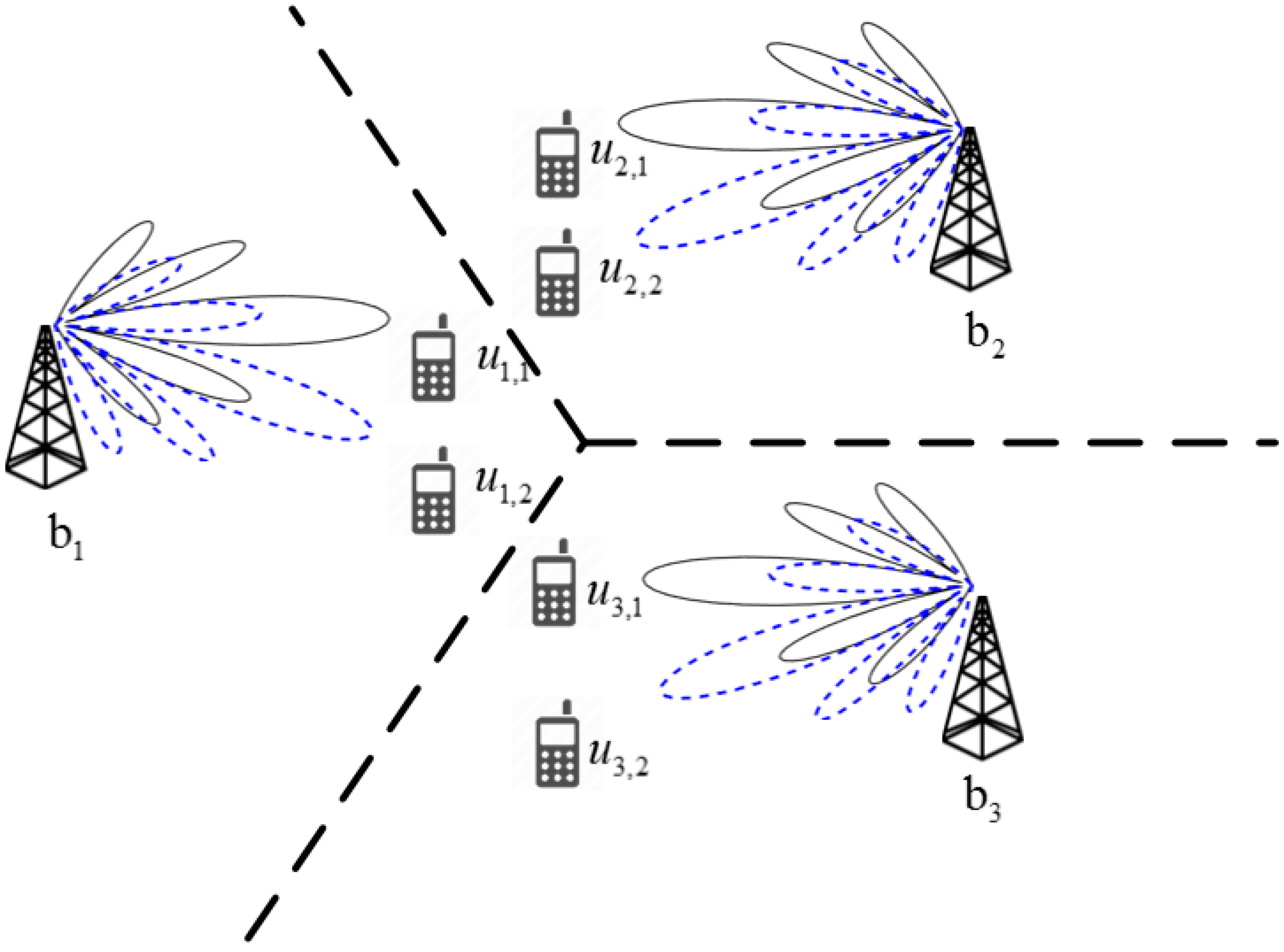
As shown in Figure 1, the signal received at an MS in an mm-wave system with a hybrid beamformer under a multicell multiuser environment can be expressed as follows:
where is the signal received at the MS , which is given by a superposition of signals transmitted from neighboring BSs . In addition, is the m-th MS served by the -th BS, is the number of neighboring BSs, is the RF combiner of MS , is the channel between the BS and MS , and is the noise component. denote the RF precoder, baseband precoder, and symbol transmitted from BS , respectively. Here, denote the number of antenna arrays, number of RF chains, and number of streams, respectively, all at the BS. The analog precoder is called the RF precoder, while the digital precoder is called the baseband precoder. Moreover, the transmitted symbol is assumed to be circular [24]. Then, the signal transmitted from the BS with a hybrid beamformer can be expressed as
The RF precoder is usually implemented by a phase shifter. Its entry is given by , where is the quantized angle of the phase shifter. A ray-based channel model is normally used for mm-wave channels because of a strong line-of-sight (LOS) path component and limited scattering components. Here, we ignore the effect of carrier frequency offset (CFO) and time delays of multi-path channel [25,26]. The delay term for each multipath component is ignored for notational simplicity because, in the following sections, only dominant path (LOS) is considered for the design of proposed precoders. In this paper, it is assumed that each BS is equipped with multiple beamforrming antennas and serves a number of MSs simultaneously. However, only one beam is formed in the direction of LOS path for each MS. Then, the channel with paths can be expressed as
where is the channel matrix between the BS and MS , and is the gain of the -th path between the BS and MS . In addition, denote the antenna array response vectors of the -th path at the BS and MS , respectively.
When a uniform planar array (UPA) is used, the antenna response vector is given by
where denote the azimuth and elevation angles of departure (AoD), and denote azimuth and elevation angles of arrival (AoA), respectively. denotes the number of antenna arrays at the MS. In addition, is the distance between antenna elements, and and are indices of the two axes formed in the antenna array plane.
In a multiuser communication system, multiple antennas allow the BS to transmit multiple data streams to a number of MSs simultaneously. In the case of conventional low-frequency communication systems, many different precoding techniques such as channel inversion, block diagonalization, dirty paper coding (DPC), and Tomlinson–Harashima precoding (THP) have been used to reduce the co-channel interference in multiuser systems under the assumption that full channel information is available at the BS [19]. However, in mm-wave systems, it is difficult to obtain full channel information at the BS because mm-wave systems with a large number of antennas require large training and feedback overhead. In [20,21,22,23], a two-stage hybrid precoding algorithm for multiuser mm-wave systems is proposed to reduce the computational complexity using the sparse nature of mm-wave channels. In the first stage, Tx–Rx beamforming is performed in the analog (RF) domain to maximize the desired signal power, ignoring the IBI among MSs. In the second stage, the digital precoder is designed to minimize IBI among MSs. The computational complexity and feedback overhead can be significantly reduced by dividing the calculation of the precoder into two stages. However, in a multicell multiuser environment, the MS may receive IBI not only from a serving BS but also from neighboring BSs, because the beams formed toward MSs in the serving cell may generate significant interference to MSs in neighboring cells, especially for MSs at the cell boundary. In this paper, we propose digital precoding techniques that can reduce IBI in mm-wave cellular systems with a hybrid beamformer, considering interference signals not only from the serving cell but also from neighboring cells. In the proposed technique, we also use the two-stage approach to reduce computational complexity and feedback overhead.
We made the following three assumptions in the design of the proposed digital precoder. First, the first stage of Tx–Rx beamforming has been successfully performed in the analog (RF) domain, ignoring the IBI among MSs. Thus, in this paper, we focus on the design of a digital precoder (second stage) that can reduce IBI from neighboring cells as well as the serving cell. Second, there is no information loss in the feedback channel in which the effective channel values estimated by MSs are transmitted. Third, the effective channel information transmitted by MSs is shared with neighboring BSs through a backhaul link without any information loss.
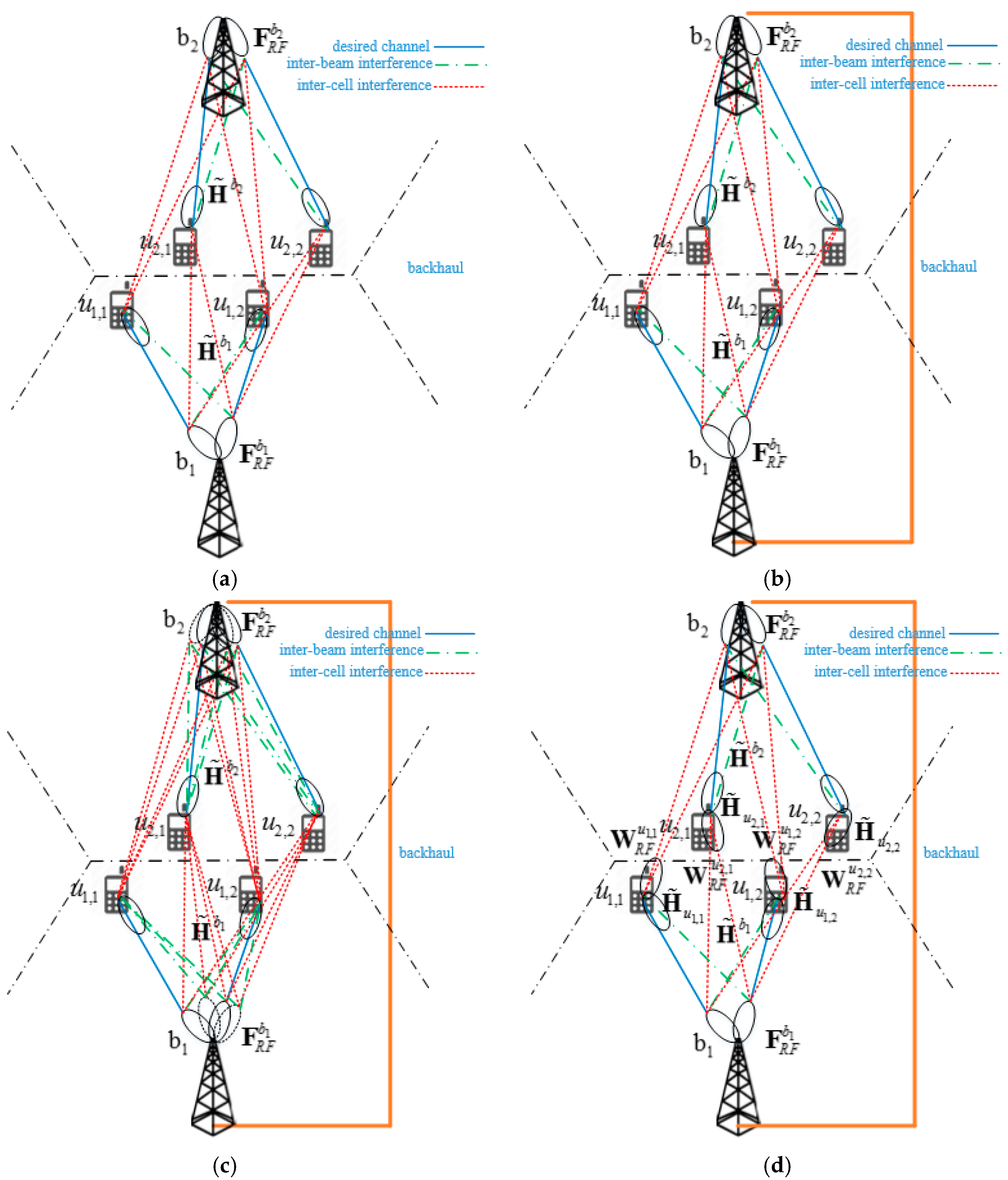
Figure 2 shows four different types of digital precoding techniques for IBI reduction in mm-wave cellular systems with a hybrid beamformer. In this figure, the lines between BSs and MSs show the directions of interferences as well as the beam directions between the BS and desired MSs. Here, solid lines represent the beam directions between the BS and desired MSs. The broken and dotted lines represent inter-beam and inter-cell interferences, respectively, when analog beams are formed in the direction of desired MS.
2.1. Type-1 Precoder
In a Type-1 precoder, the previous digital precoder developed for a single-cell multiuser environment is directly applied to a multicell multiuser environment. In this case, analog beams are formed in the direction of MSs in each cell, as shown in Figure 2a. Beam direction in this figure is obtained after completion of the first stage. Here, the solid line between the left beam of BS and the MS represents the beam direction between the serving BS () and desired MS (). The solid line between the right beam of BS and the MS represents the beam direction between the serving BS () and desired MS (). The broken line between the right beam of BS and the MS represents the direction of inter-beam interference in the serving cell. The inter-beam interference is mainly caused by the sidelobe of analog beam formed toward MS in the serving cell. The dotted lines between two beams of neighboring BS and the MS represent the directions of inter-cell interference. The channel coefficients associated with these lines correspond to the elements of the effective network channel matrix. In a Type-1 precoder, the RF precoder in each cell is given by
where is the RF precoder of the -th BS and is the array response matrix of the -th BS. We assumed that the number of MSs served by a BS is . That is, a BS transmits multiple streams simultaneously to MSs using the RF precoder obtained in the first stage. Here, the MSs served by the -th BS are denoted by . However, in a multicell multiuser environment, a new channel model is needed to take into account the interference terms transmitted from neighboring BSs. Here, we define an effective network channel of , which can be viewed as the effective channel matrix between the BS and all MSs in neighboring cells (including the serving cell). The term “effective” is used to indicate that the RF precoder of the BS and the RF combiner of the MS are included in the channel model. From the perspective of the BS , an effective network channel can be expressed as
The effective network channel of includes not only the effective channels between the BS and MSs in the serving cell, but also the effective channels between the BS and MSs in the neighboring cells. Here, the total number of MSs, denoted by , is because the number of neighboring BSs is . A baseband precoder can be designed if we can obtain an inverse matrix of the effective network channel as follows:
where denotes a pseudo inverse matrix operation. However, we cannot find the pseudo inverse matrix for because the effective network channel is given by a rectangular matrix with a large number of rows (). Thus, the zero-forcing (ZF) precoder, which is widely used in multiuser communication, cannot be obtained in a multicell multiuser environment. Note that the ZF precoder in a single-cell multiuser environment is given by an inverse (square) matrix of . In the Type-1 precoder, the ZF precoding technique for a single-cell multiuser is applied to each cell. It is expected that the Type-1 precoder cannot achieve a high capacity because it cannot reduce the IBI from neighboring cells.
When the Type-1 precoder is used, the achievable rate of the MS served by the BS is given by
where denotes the total transmission power of the BS. Note that and denote the BS and the MSs, respectively, which are served by the BS. In addition, and denote the (U * (n − 1) + m)-th column vector of and the variance of Gaussian noise, respectively. The first term in the denominator represents the interference caused by adjacent beams in the serving cell, and the second term represents the interference caused by beams from neighboring BSs. The sum-rate and average-rate of the system are given by
2.2. Type-2 Precoder
In the Type-1 precoder, we cannot find a pseudo inverse matrix for the effective network channel. To solve the problem, we define an effective combined network channel as a square matrix combining all effective network channels in neighboring cells. The information on the effective network channel is shared by a backhaul link, as shown in Figure 2b. The effective combined network channel is defined by
Unlike (6), becomes a square matrix. In a Type-2 case, a ZF precoder for the effective combined network channel is obtained as follows:
In a cellular system with the Type-2 precoder, the IBI reduction cannot be performed independently by each BS because the Type-2 precoder is operated on the network-level consisting of all neighboring BSs. In other words, during the data transmission period, all BSs should share data streams and transmit data streams simultaneously to all MSs. The number of beams that eventually formed at the BS is the same as that of all MSs, (), which is much larger than used in the first stage of the RF precoder design. The achievable rate of the MS served by the BS in the Type-2 precoder is given by
If interferences received from all neighboring BSs are cancelled with a perfect estimation of all effective network channels, the interference term in the denominator of (12) will become zero.
2.3. Type-3 Precoder
The Type-2 precoder requires a large network overhead because the precoder is operated on the network-level consisting of all neighboring BSs. To reduce the network overhead, the BS with a Type-3 precoder forms analog beams in the direction of not only the MSs in the serving cell but also the MSs in the neighboring cell, as shown in Figure 2c. In this case, the Type-3 precoder allows us to design the digital precoder of each BS independently. The RF precoder in the Type-3 precoder is given by
The effective network channel for each BS with the Type-3 precoder is given by (6). However, unlike the Type-1 precoder, the effective network channel for the BS with the Type-3 precoder, , becomes a square matrix because of the increase in the number of RF precoder. In the Type-3 case, a ZF precoder for the effective network channel is obtained as follows:
Unlike the Type-2 case, the BS with the Type-3 precoder can operate independently during the data transmission period. In addition, the number of beams that eventually formed at the BS is the same as the number of MSs in the serving cell, . Using (6) and (13), the effective network channel in the Type-3 case can be expressed as
If and the RF combiner of the MS is correctly steered to the direction of the BS , the equation is always satisfied. In addition, the hybrid precoder satisfies the following power constraint:
Then, the precoder in (14) can be rewritten as follows:
where represents the diagonal matrix inserted to satisfy the power constraint in (16). denotes the (U * (n − 1) + m)-th row vector of . Using (13) and (17), (16) can be rewritten as
Using (15) and (18), can be expressed as
when the interference signals are completely removed by the Type-3 precoder, the achievable rate in (8) is given by
2.4. Type-4 Precoder
A Type-4 precoder is proposed for the case where a hybrid beamformer is available at the MS as well as the BS. In the Type-4 case, the precoder at the BS removes only the interference from adjacent beams in the serving cell, while the combiner at the MS is designed to remove interference from neighboring cells. As shown in Figure 2d, the BS forms beams in the directions of MSs in the serving cell, while the MSs form beams in the direction of not only the serving BS, but also neighboring BSs that generate interference to MSs in the serving cell. For example, in Figure 2d, the MS forms beams in the directions of BSs and . The precoder at the BS removes the inter-beam interference in the serving cell, while the combiner at the MS removes interference from neighboring BS . In the Type-4 case, the RF precoder at the BS is given by
A digital precoding technique at the BS in the Type-4 case is the same as that in the Type-1 case. The RF combiner at the MS is given by
where denotes the antenna-array response vector at the MS formed toward the BS . The effective network channel of the BS in the Type-4 case is given by
Unlike (6) in the Type-1 case, only MSs in the serving cell are considered in the effective network channel in (23). In the Type-4 case, the MS also forms an effective network channel as follows:
where denotes an effective network channel of the MS . The baseband combiner at the MS is designed as
The number of analog beams required at the BS in the Type-4 case is , which is much smaller than that in the Type-3 case. Thus, a smaller number of RF chains is required at the BS in the Type-4 case. However, the number of RF chains required at the MS in the Type-4 case increases from 1 to . In the Type-4 case, the achievable rate of the MS in the serving the BS is given by
Unlike the Type-3 case, the baseband combiner of the MS is reflected in the achievable rate in the Type-4 case. As in (15), the effective network channel of the BS can be written as
Note that the effective network channel in (27) considers only MSs in the serving cell. Using the result in (19), the diagonal matrix for the power constraint in the BS precoder can be expressed as
From (24), the effective network channel of the MS can be rewritten as
The diagonal matrix for the power constraint in the baseband combiner of the MS can be obtained in a similar way, as follows:
The effective network channels in (27) and (29) can be estimated independently at the BS and MS, respectively. Thus, the digital precoder at the BS and combiner at the MS can be designed independently in the Type-4 case. To obtain an achievable rate in the Type-4 precoder, the numerator in (26) is rewritten as
Then, the averaged achievable rate is given by
From (32), one can see that the averaged achievable rate in the Type-4 precoder is affected by not only the array response matrix of the BS, but also the array-response matrix of the MS.
In summary, in this section, we propose four different precoding techniques to reduce the IBI in mm-wave cellular systems with a hybrid beamformer. The Type-1 precoder is simple because the precoding technique developed for a single-cell multiuser environment is applied to each cell. However, in this case, we cannot reduce the interference from neighboring cells. The Type-2 precoder can reduce interference from both the serving cell and neighboring cells because the precoder is designed for the combined network consisting of all neighboring cells. However, in this case, all BSs should share data streams, increasing the network overhead. In the Type-3 precoder, the RF precoder is extended such that the digital precoder can be designed independently by each BS. However, in this case, the number of RF chains that are required at the BS increases as the number of neighboring cells increases. The Type-4 precoder can be used when a hybrid beamformer is available at the MS as well as at the BS. In this case, the number of RF chains required at the BS is reduced to a single-cell case; however, the number of RF chains required at the MS increases by the number of neighboring cells.
2.5. Channel Estimation
So far, we assumed that the channel information required for the precoder design is known perfectly. However, the channels between the MS and neighboring BSs, as well as the channel between the MS and the serving BS, should be estimated beforehand for the design of the proposed precoder. The processing time required for channel estimation in the proposed approach increases proportionally to the product of the number of neighboring cells and the number of Tx beams. In order to reduce the processing time significantly, we apply the cell and beam reference signal (CBRS) technique to the effective network channel estimation for the design of the proposed precoder [18]. Here, we assume that the RF precoder in the BS and the RF combiner in the MS are successfully obtained after completion of the first stage in the analog domain.
In the CBRS technique, multiple beams are transmitted simultaneously from neighboring BSs (including the serving cell) to reduce the processing time for channel estimation. In order to estimate all channels between the MS and neighboring BSs with multiple beams, CBRSs are simultaneously transmitted from multiple beams of neighboring BSs. The CBRS carries a cell ID (CID) as well as a beam ID (BID). If the CBRS carries only BID information, it will be impossible to determine which cell had transmitted the BID. Therefore, a large number of different sequences (CID × BID) need to be generated. In the proposed CBRS technique, the BID is designed in conjunction with CID because the BID must be detected in a multicell environment. The hierarchical structure of CBRS gives the advantage of enabling the reuse of the same BIDs in neighboring cells, enabling us to generate a large set of sequences.
The CBRS technique can be viewed as a combination of a Chu sequence and a polyphase sequence. In the CBRS technique, a sequence is generated by mapping the CID to the root index of the Chu sequence, and the BID to the index of the polyphase sequence. The Chu sequence is selected as a base sequence because it is widely used in the design of synchronization signals and the random access preamble in Long Term Evolution (LTE) systems owing to its good correlation property [27]. A combination of a Chu sequence and a polyphase sequence is selected for CBRS because these signals can be transmitted simultaneously with minimal IBI in a multicell environment. The CBRS is defined by the product of a prime-length Chu sequence and a polyphase sequence in the frequency domain as follows:
where denote a prime-length Chu sequence and polyphase sequence, respectively. In addition, denote the root index of the Chu sequence, index of polyphase sequence, set of CIDs, and set of BIDs, respectively. , , and denote the number of available CIDs, BIDs, and sequence length, respectively. is a parameter used to avoid the incorrect detection of the cell ID when there is a symbol timing offset (STO).
The beams are generated by the RF precoder at the BS, which is obtained after completion of the first stage. The signal received at the MS after CBRS transmission is given by
Note that only the RF precoder is used at the BS. The baseband precoder will be designed in the second stage using the information of the estimated channels. Here, denotes the CBRSs that are transmitted from the BS . The MS estimates the effective network channel using the correlation property of the CBRS. The highest peak occurs when the reference BID is matched with the transmitted BID . The correlator output becomes zero when the reference BID is not matched with the transmitted BID. The correlator output becomes a small value () when the reference CID and BID is not matched with the transmitted CID and BID . Using these properties, the MS can estimate all effective channels in neighboring cells by correlating the received signal with all possible reference CIDs and BIDs.
If the total number of beams to be generated in neighboring BSs is smaller than the number of BIDs generated by the CBRS, it will be advantageous to allocate the same CID to the neighboring BSs. In this case, no IBI will occur owing to the ideal correlation property, which allows us to estimate all channels accurately. However, if the total number of beams to be generated in neighboring BSs is larger than the number of BIDs , it will be advantageous to allocate the same CID to the BSs located near the serving BS, and to allocate different CIDs to the BSs located far way. In this case, the interference term (), which is generated by the BS located far way, will be reduced further owing to the path loss.
3. Simulation
In this section, we evaluate the performance of the proposed hybrid beamforming technique for the reduction of IBI in mm-wave cellular systems. To do this, we perform computer simulations in a simple scenario shown in Figure 2. Here, we assume that four MSs are served by each BS in a three-cell environment. The BS and MS employ 8 × 8 and 4 × 4 UPAs, respectively. We also assumed that MSs are located randomly in a cell, and that a single LoS path is present between the BS and MS. The azimuth and elevation angles of AoD at the BS follow uniform distributions of (0, π) and (0, π/2), respectively. The path gain and the transmission power of BS are all normalized to 1. More sophisticated simulation can be performed with an accurate mm-wave channel model under realistic assumption [28].
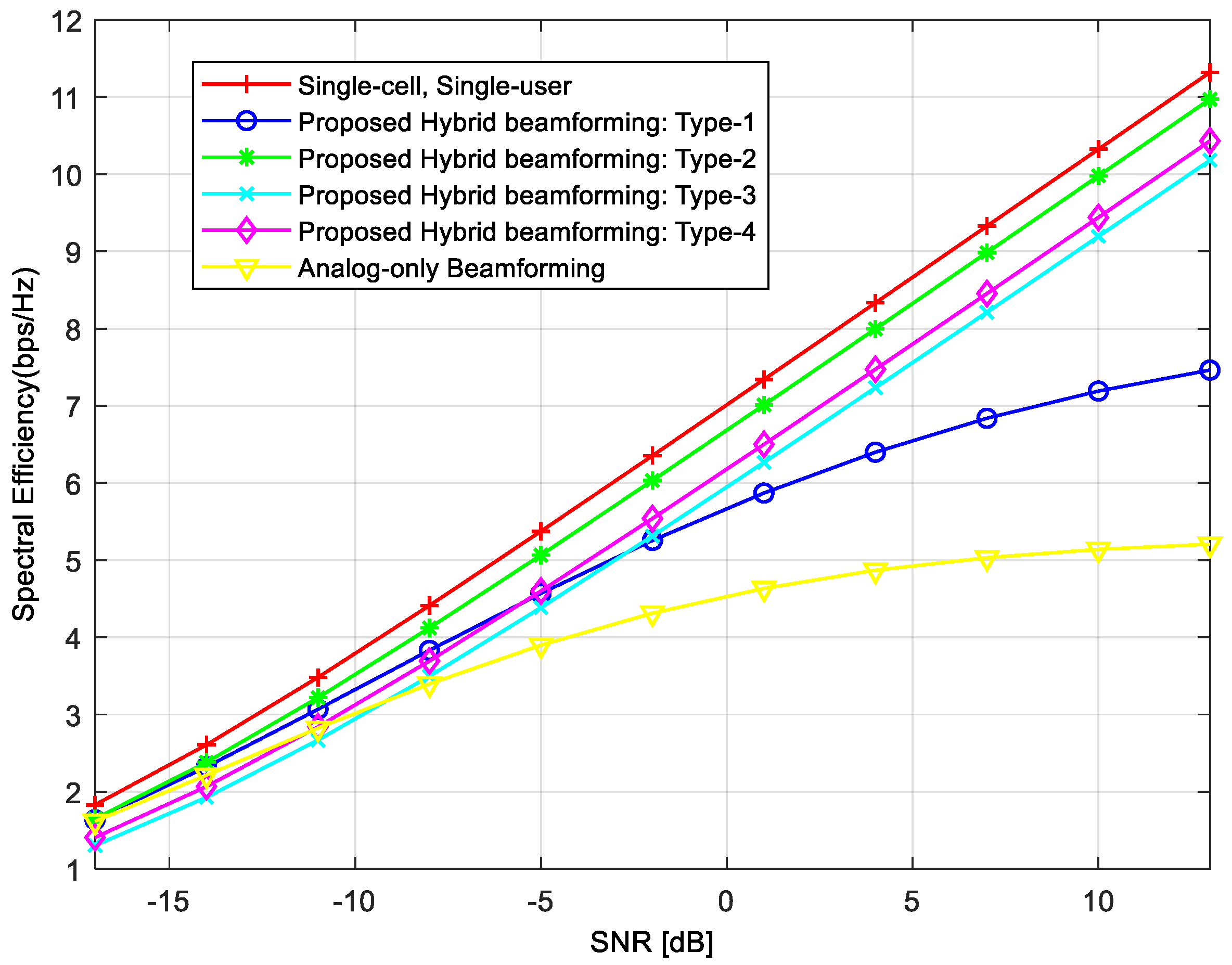
In the first numerical simulation, we compared the averaged achievable rates per user for different hybrid beamforming techniques. In Figure 3, the legend “analog-only beamforming” refers to the case where only the RF precoders are used. In this case, beams are formed in the direction of MSs to maximize the desired signal power. However, its averaged achievable rate per user is the lowest because, in this case, we did not consider IBI. We can achieve the highest averaged achievable rate when we used the beamformer with “Single-cell, Single-user.” In this case, the best performance is achieved because there is no IBI from the serving cell or neighboring cells. The averaged achievable rates of the proposed hybrid beamforming techniques lie between “Analog-only Beamforming” and “single-cell, single-user”. The Type-1 precoder has the lowest achievable rates among the proposed techniques, and its achievable rate does not increase linearly as SNR increases because the interference from neighboring BSs is not removed. Note that the Type-1 precoder removes IBI in the serving cell, and does not consider IBI from neighboring cells. The achievable rates of Type-2, Type-3, and Type-4 precoders increase linearly as SNR increases, because the IBI from neighboring cells as well as the serving cell is reduced. The achievable rate is higher in the order of Type-2, Type-3, and Type-4 precoders (i.e., the highest is Type-2).
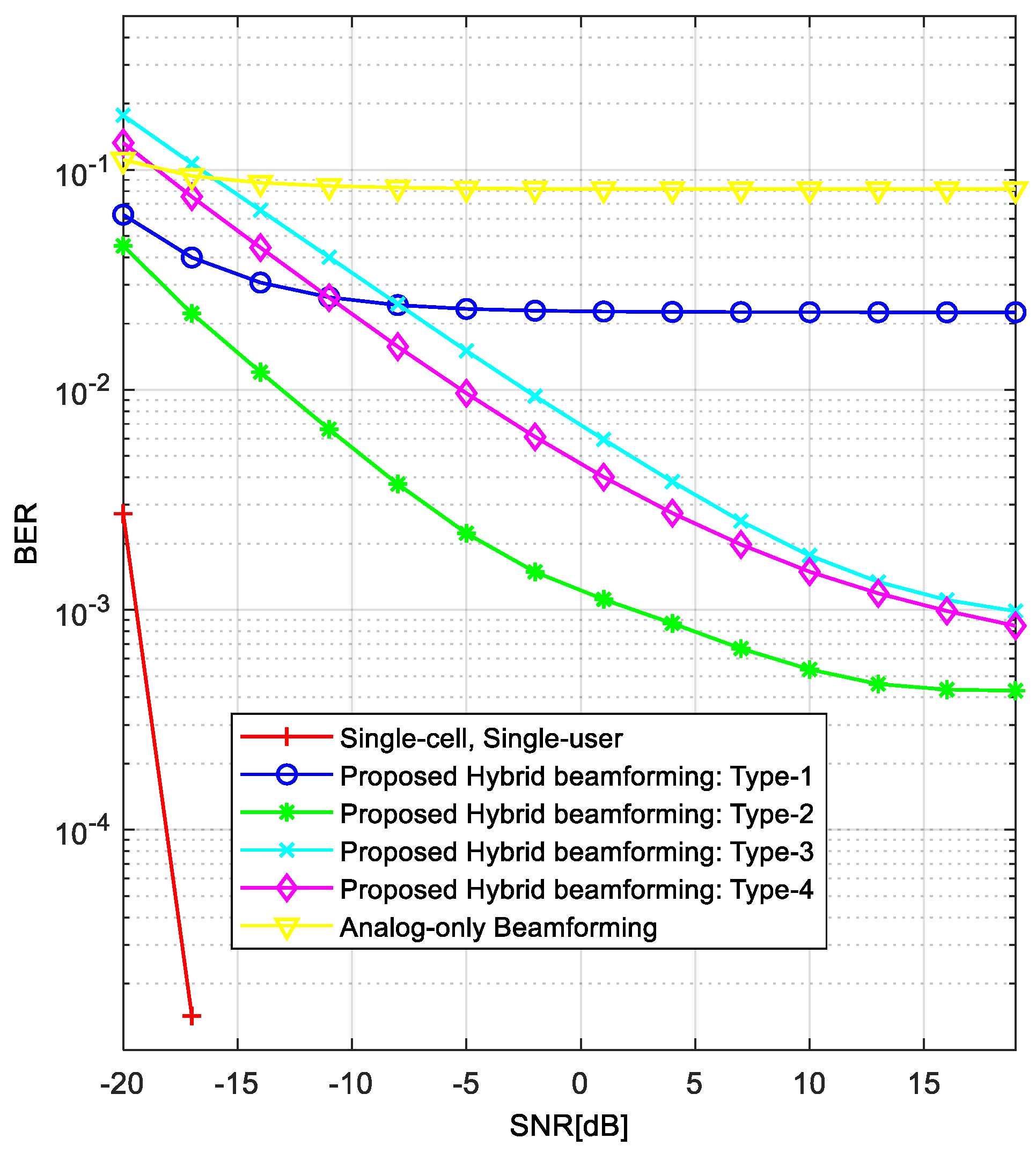
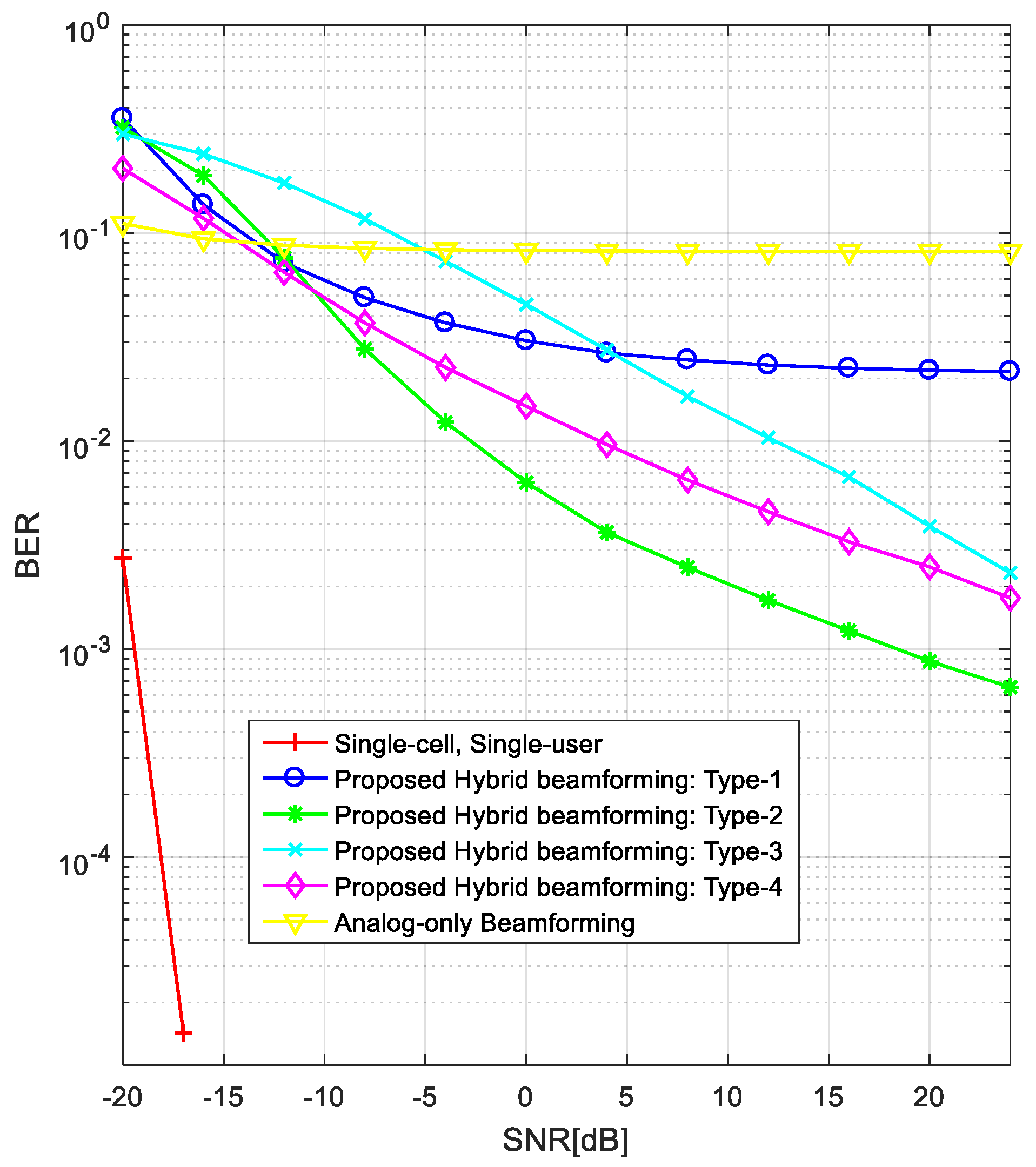
Figure 4 compares the BER performance of different hybrid beamforming techniques in the same environment as in Figure 3. By comparing these two figures, we can see that the BER performance in Figure 4 is consistent with the averaged achievable rates in Figure 3. This is because the achievable rate per user increases as the interference decreases, resulting in a decreased BER. The “analog-only beamforming” case shows the worst performance (error floor) because IBI is not considered. In addition, the “Single-cell, Single-user” case shows the best performance because there is no IBI. The Type-1 precoder shows the lowest performance (error floor) of the proposed techniques because it cannot reduce the IBI from neighboring cells. The BER performance is better in the order of Type-2, Type-3, and Type-4 precoders (i.e., the best is Type-2). The reason for which the BER curves show noticeable performance gaps compared with the achievable rates is that the BER curve reflects the worst case more significantly. For the BER simulation, we randomly selected the values of AoAs and AoDs between BSs and MSs. In the process of averaging the error rates, the lowest error rate usually dominates the averaged BER performance.
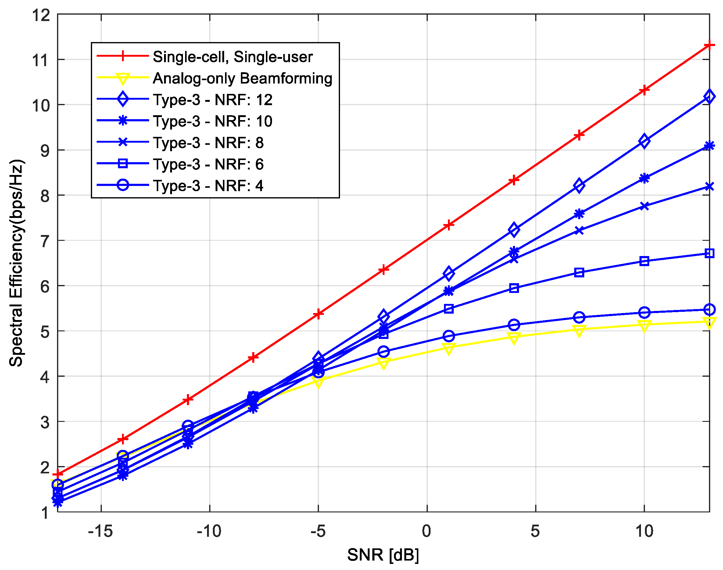
Type-1, Type-2, and Type-4 precoders require at least U RF chains to serve U MSs simultaneously in the serving cell. However, the number of RF chains in Type-3 precoder needs to be equal to or greater than the number of total MSs in neighboring cells to remove IBI. In the cellular system with 12 MSs in 3 neighboring cells, 12 RF chains are required for each BS to remove IBI. If the number of RF chains is smaller than 12, performance may degrade due to the remaining IBI. Figure 5 shows the achievable rate of Type-3 precoder when the number of RF chains varies. In simulation, the number of RF chains is changed from 4 to 12. As can be seen in the figure, the achievable rate decreases as the number of RF chains decreases. When the number of RF chains is 4, the performance of Type-3 precoder is similar to that of “Analog-only Beamforming” because Type-3 precoder cannot remove the IBI due to the insufficient number of RF chains.
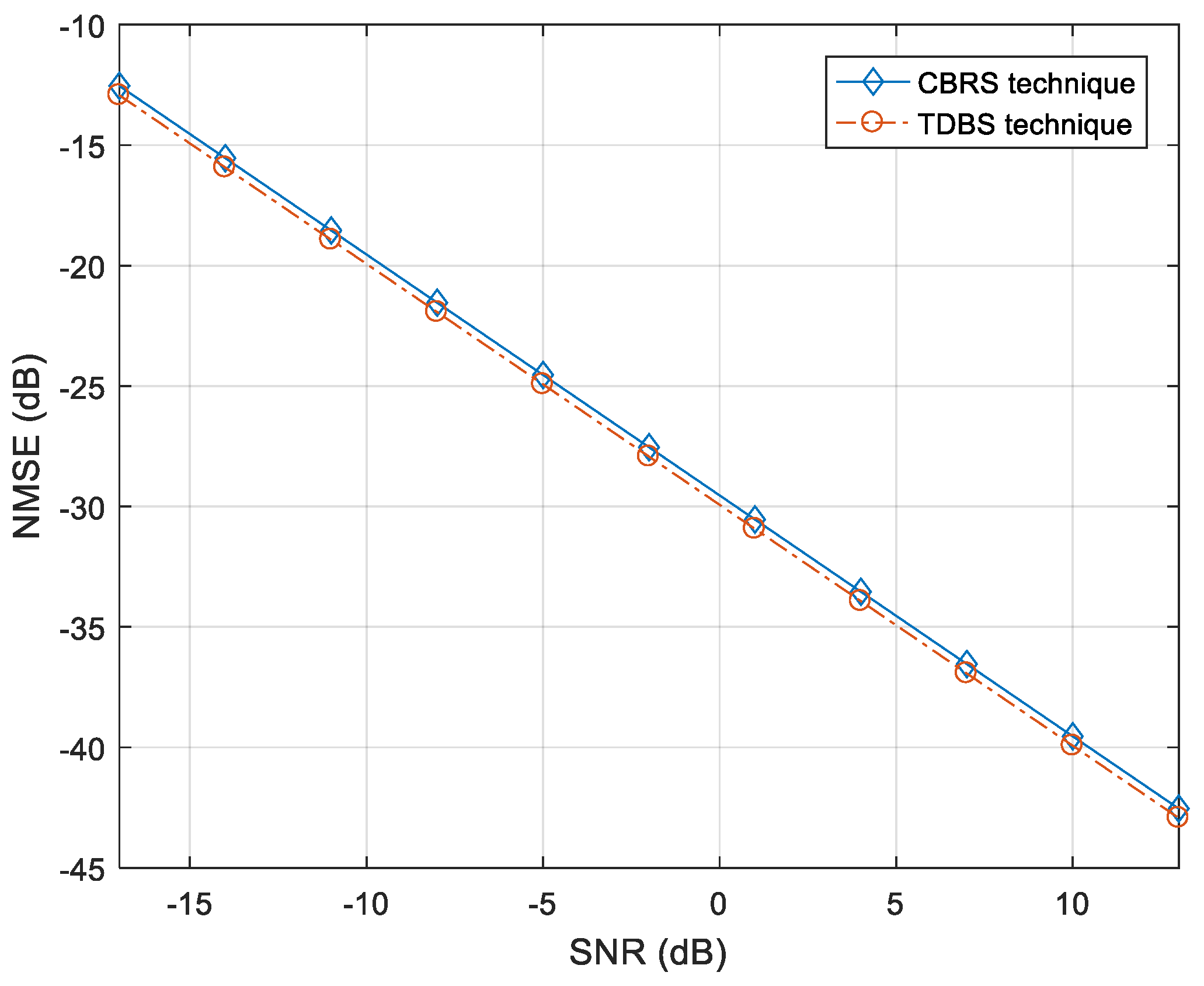
Figure 6 shows the performance comparison when we used the CBRS technique and the time-division beam switching (TDBS) technique for channel estimation in the environment of Figure 2. In the CBRS technique, multiple beams with the same CID but different BIDs are transmitted simultaneously from neighboring BSs. In the TDBS technique, single Tx beams are individually transmitted from the BS until all of the Tx beams are transmitted. This process is repeated for neighboring BSs. The processing time required for beam transmission in TDBS increases proportionally to the product of the number of Tx beams and the number of neighboring BSs. As can be seen in Figure 6, the performances of two different channel estimation techniques are similar. It can be seen that the CBRS technique allows us to estimate the effective network channel with a minimal IBI in a multicell environment.
In Table 1, we compare the processing times required for channel estimation in the CBRS and TDBS techniques. Here, it is assumed that the subcarrier spacing kHZ and the symbol time μs [13]. In the CBRS technique, the processing time required for channel estimation is one orthogonal frequency-division multiplexing (OFDM) symbol period because the CBRSs are transmitted simultaneously from neighboring BSs with multiple beams. Here, we ignore the time required to calculate the value of the channel estimate. The processing time required for beam transmission in the TDBS technique increases as the number of Tx beams and the number of neighboring BSs increase. When the TDBS technique is used for channel estimation and Type-1/Type-2/Type-4 precoders are used for interference reduction, the processing time required for channel estimation is increased by because each BS needs to send one beam at a time to MSs in the serving cell. In the Type-3 case, the processing time is increased by because each BS needs to send beams in the direction of not only MSs in the serving cell but also MSs in neighboring cells. For example, when , the TDBS technique with the Type-1 and Type-3 precoders requires processing times that are 15 and 45 times longer, respectively, than with the CBRS technique.
Table 2 compares the sizes of the matrix and computational complexities required for proposed precoders. Since the digital precoders are designed using the estimated effective network channel matrices, the computational complexity of the proposed precoder is proportional to the size of the effective network channel matrices. As shown in Table 2, Type-2 and Type-3 precoders require the highest computational complexity. The followings are Type-1 and Type-4 precoders. The computational complexity is important in sensor networks because processing resources are constrained in most sensor nodes. The proposed precoders except Type-4 precoder do not require processing resources at the sensor node. All the computations required for the design of precoder are performed at the BS. The MS needs only to feedback the channel information to the BS. However, in Type-4 precoder, the MS needs processing resources to remove the IBI from adjacent cells. Note that, in the Type-4 case, the precoder at the BS removes only the interference from adjacent beams in the serving cell, while the combiner at the MS is designed to remove interference from adjacent cells. Table 2 also shows computational complexities required for the BS and MS (sensor node) when the proposed precoders are used. As can be seen in Table 2, all the computations required for the design of precoder (except Type-4 precoder) are performed at the BS. Thus, Type-1, Type-2, and Type-3 precoders can be easily applied to sensor networks because no additional hardware and processing resources are not required for sensor nodes. However, it may be difficult to apply the Type-4 precoder to typical sensor networks because the Type-4 precoder requires the hybrid beamformer and processing resources in sensor nodes.
Figure 7 compares the BER performances of different hybrid beamforming techniques when we used the channel estimated by the CBRS technique. As can be seen in this figure, the BER performances of the proposed hybrid beamforming techniques are slightly degraded owing to the channel estimation error, compared with the results in Figure 4. The channel estimation error comes from the noise part in the received signal because mobility is not considered in this simulation. However, the overall trend in the performance is similar. Note that the BER performances of “Analog-only Beamforming” and “Single-cell, Single-user” are the same as in Figure 4 because the channel information is not used in these cases.
4. Conclusions
In this paper, we proposed digital precoding techniques for mm-wave systems with a hybrid beamformer, which can reduce the IBI received from neighboring cells as well as adjacent beams in the serving cell. We performed simulations, and the results show that while the Type-1 precoder is simple, it cannot reduce the IBI from neighboring cells, resulting in an error floor in BER performance. They also show that Type-2/Type-2/Type-3 precoders can achieve high achievable rates or low BERs because they can reduce the IBI from the serving cell and neighboring cells. The advantages and disadvantages of the precoders can be summarized as follows. In the Type-2 case, the number of RF chains required at the BS is the same as in a single-cell case. However, all neighboring BSs should share data streams, increasing the network overhead. In the Type-3 case, the digital precoder can be designed independently by each BS. However, the number of RF chains required at the BS increases. In the Type-4 case, the number of RF chains required at the BS is reduced to that of a single-cell case. However, the number of RF chains required at the MS increases. In addition, we showed that the processing times required for the estimation of the effective combined network channel can be significantly reduced using the CBRS technique. Finally, we showed that the proposed precoders (Type-2/Type-2/Type-3) with the estimated effective network channel can significantly reduce the IBI in mm-wave cellular systems. As a future work, the performance of the hybrid precoder needs to be analyzed in the environment where MSs move.
Acknowledgments
This research was supported by Basic Science Research Program through the National Research Foundation of Korea (NRF) funded by the Ministry of Education (2015R1D1A1A01057628), and by Chung-Ang University Graduate Research Scholarship in 2017.
Author Contributions
(ONLY for Research Articles): Sung Joon Maeng and Su Ho Park developed a cell selection technique for mm-Wave cellular systems with hybrid beamforming. Yong Soo Cho supervised the project.
Conflicts of Interest
The authors declare no conflicts of interest.
References
- Cudak, M.; Kovarik, T.; Thomas, T.A.; Ghosh, A.; Kishiyama, Y.; Nakamura, T. Experimental mm Wave 5G Cellular System. In Proceedings of the GLOBECOM 2014, Austin, TX, USA, 8–12 December 2014. [Google Scholar] [CrossRef]
- Rangan, S.; Rappaport, T.S.; Erkip, E. Millimeter-Wave Cellular Wireless Networks: Potentials and Challenges. Proc. IEEE 2014, 102, 366–385. [Google Scholar] [CrossRef]
- Rappaport, T.S.; Sun, S.; Mayzus, R.; Zhao, H.; Azar, Y.; Wang, K.; Gutierrez, F. Millimeter-Wave Mobile Communications for 5G Cellular: It will Work! IEEE Access 2013, 1, 335–349. [Google Scholar] [CrossRef]
- Rappaport, T.S.; Gutierrez, F.; Ben-Dor, E.; Murdock, J.N.; Qiao, Y.; Tamir, J.I. Broadband Millimeter-Wave Propagation Measurements and Models Using Adaptive-Beam Antennas for Outdoor Urban Cellular Communications. IEEE Trans. Antennas Propag. 2013, 61, 1850–1859. [Google Scholar] [CrossRef]
- Méndez-Rial, R.; Rusu, C.; González-Prelcic, N.; Alkhateeb, A.; Heath, R.W. Hybrid MIMO Architectures for Millimeter Wave Communications: Phase Shifters or Switches? IEEE Access 2016, 4, 247–267. [Google Scholar] [CrossRef]
- Hur, S.; Kim, T.; Love, D.J.; Krogmeier, J.V.; Thomas, T.A.; Ghosh, A. Millimeter-Wave Beamforming for Wireless Backhaul and Access in Small Cell Networks. IEEE Trans. Commun. 2013, 61, 4391–4403. [Google Scholar] [CrossRef]
- Heath, R.W.; González-Prelcic, N.; Rangan, S.; Roh, W.; Sayeed, A.M. An Overview of Signal Processing Techniques for Millimeter Wave MIMO Systems. IEEE J. Sel. Top. Signal Proc. 2016, 10, 436–453. [Google Scholar] [CrossRef]
- Berraki, D.E.; Armour, S.M.; Nix, A.R. Application of Compressive Sensing in Sparse Spatial Channel Recovery for Beamforming in mmWave Outdoor Systems. IEEE Wirel. Commun. Netw. Conf. 2014, 887–892. [Google Scholar] [CrossRef]
- Ayach, O.E.; Rajagopal, S.; Abu-Surra, S.; Pi, Z.; Heath, R. Spatially Sparse Precoding in Millimeter Wave MIMO systems. IEEE Trans. on Wireless Comm. 2014, 13, 1499–1513. [Google Scholar] [CrossRef]
- Alkhateeb, A.; El Ayach, O.; Leus, G.; Heath, R.W. Channel Estimation and Hybrid Precoding for Millimeter Wave Cellular Systems. IEEE J. Sel. Top. Signal Proc. 2014, 8, 831–846. [Google Scholar] [CrossRef]
- Song, J.; Choi, J.; Love, D.J. Codebook Design for Hybrid Beamforming in millimeter wave systems. In Proceedings of the IEEE International Conference on Communications, London, UK, 8–12 June 2015. [Google Scholar]
- IEEE 802.11ad Standard, Part 11: Wireless LAN Medium Access Control (MAC) and Physical Layer (PHY) Specification; IEEE: New York, NY, USA, 2012. [CrossRef]
- IEEE 802.15.3c Part 15.3, Wireless Medium Access Control (MAC) and Physical Layer (PHY) Specifications for High Rate Wireless Personal Area Networks (WPANs) Amendment 2: Millimeter-wave-based Alternative Physical Layer Extension; IEEE: New York, NY, USA, 2009.
- Li, B.; Zhou, Z.; Zhang, H.; Nallanathan, A. Efficient Beamforming Training for 60-GHz Millimeter-wave Communications: A Novel Numerical Optimization Framework. IEEE Tran. Veh. Technol. 2014, 63, 703–717. [Google Scholar] [CrossRef]
- KT PyeongChang 5G Special Interest Group (KT 5G-SIG). KT 5th Generation Radio Access; Physical Layer; Physical Channels and Modulation (Release 1); KT PyeongChang 5G Special Interest Group: Seongnam, Korea, 2016. [Google Scholar]
- KT PyeongChang 5G Special Interest Group (KT 5G-SIG). KT 5th Generation Radio Access; Physical Layer; Physical Layer Procedures (Release 1); KT PyeongChang 5G Special Interest Group: Seongnam, Korea, 2016. [Google Scholar]
- 3rd Generation Partnership Project (3GPP). TS 38.213-V1.2.0-3rd Generation Partnership Project. In Technical Specification Group Radio Access Network; NR; Physical Layer Procedures for Control (Release 15); 3GPP: Valbonne, France, 2017. [Google Scholar]
- Saquib, K.M.; Maeng, S.J.; Cho, Y.S. Cell Selection Technique for Millimeter-Wave Cellular Systems with Hybrid Beamforming. Sensors 2017, 17, 1461. [Google Scholar]
- Stankovic, V.; Haardt, M. Generalized Design of Multi-User MIMO Precoding Matrices. IEEE Trans. Wirel. Commun. 2008, 7, 953–961. [Google Scholar] [CrossRef]
- Raghavan, V.; Subramanian, S.; Cezanne, J.; Sampath, A.; Koymen, O.H.; Li, J. Single-User Versus Multi-User Precoding for Millimeter Wave MIMO Systems. IEEE J. Sel. Areas Commun. 2017, 35, 1387–1401. [Google Scholar] [CrossRef]
- Sohrabi, F.; Yu, W. Hybrid Digital and Analog Beamforming Design for Large-Scale Antenna Arrays. IEEE J. Sel. Top. Signal Proc. 2016, 10, 501–513. [Google Scholar] [CrossRef]
- Magueta, R.; Castanheira, D.; Silva, A.; Dinis, R.; Gameiro, A. Hybrid Iterative Space-Time Equalization for Multi-User mmW Massive MIMO Systems. IEEE Trans. Commun. 2017, 65, 608–620. [Google Scholar] [CrossRef]
- Zhao, L.; Kwan Ng, D.W.; Yuan, J. Multi-User Precoding and Channel Estimation for Hybrid Millimeter Wave Systems. IEEE J. Sel. Areas Commun. 2017, 35, 1576–1590. [Google Scholar] [CrossRef]
- Darsena, D.; Gelli, G.; Verde, F. Widely-linear precoders and decoders for MIMO channels. In Proceedings of the International Symposium on Wireless Communication Systems, Ilmenau, Germany, 27–30 August 2013; pp. 587–591. [Google Scholar]
- Darsena, D.; Gelli, G.; Verde, F. Joint blind channel shortening and compensation of transmitter I/Q imbalances and CFOs for uplink SC-IFDMA systems. Phys. Commun. 2014, 11, 25–35. [Google Scholar] [CrossRef]
- Darsena, D.; Gelli, G.; Paura, L.; Verde, F. Blind channel shortening for space-time-frequency block coded MIMO-OFDM systems. IEEE Trans. Wirel. Commun. 2012, 11, 1022–1033. [Google Scholar] [CrossRef]
- Sesia, S.; Toufik, I.; Baker, M. LTE—The UMTS Long Term Evolution: From Theory To Practice; Wiley: Chichester, UK, 2011. [Google Scholar]
- Gimenez, S.; Roger, S.; Baracca, P.; Martín-Sacristán, D.; Monserrat, J.F.; Braun, V.; Halbauer, H. Performance Evaluation of Analog Beamforming with Hardware Impairments for mmW Massive MIMO Communication in an Urban Scenario. Sensors 2016, 16, 1555. [Google Scholar] [CrossRef] [PubMed]
Figure 1.
An mm-wave system with a hybrid beamformer in a multicell multiuser environment.

Figure 2.
Four different types of digital precoding techniques for reduction of inter-beam interference (IBI) in mm-wave cellular systems with a hybrid beamformer. (a) Type-1; (b) Type-2; (c) Type-3; (d) Type-4.
Figure 2.
Four different types of digital precoding techniques for reduction of inter-beam interference (IBI) in mm-wave cellular systems with a hybrid beamformer. (a) Type-1; (b) Type-2; (c) Type-3; (d) Type-4.

Figure 3.
Achievable rates of proposed hybrid beamforming techniques.

Figure 4.
BER comparison of proposed hybrid beamforming techniques.

Figure 5.
Achievable rates of Type-3 precoder when the number of radio frequency (RF) chains varies.
Figure 5.
Achievable rates of Type-3 precoder when the number of radio frequency (RF) chains varies.

Figure 6.
Performance comparison of channel estimation between cell and beam reference signal (CBRS) and time-division beam switching (TDBS) techniques.
Figure 6.
Performance comparison of channel estimation between cell and beam reference signal (CBRS) and time-division beam switching (TDBS) techniques.

Figure 7.
Comparison of BERs of proposed hybrid beamforming techniques when the estimated channel is used.
Figure 7.
Comparison of BERs of proposed hybrid beamforming techniques when the estimated channel is used.


Table 1.
Processing time required for channel estimation in the proposed and conventional techniques.
Table 1.
Processing time required for channel estimation in the proposed and conventional techniques.
| Processing Time | Example | ||
|---|---|---|---|
| CBRS technique | |||
| TDBS technique | Type-1 precoder Type-2 precoder Type-4 precoder | ||
| Type-3 precoder | |||
Table 2.
Computational complexities required for the design of the proposed precoders at base station (BS) and mobile station (MS).
Table 2.
Computational complexities required for the design of the proposed precoders at base station (BS) and mobile station (MS).
| Type-1 | Type-2 | Type-3 | Type-4 | ||
|---|---|---|---|---|---|
| BS | Matrix dimension of | ||||
| Computational complexity for calculation | |||||
| MS | Matrix dimension of | - | - | - | |
| Computational complexity for calculation | - | - | - | ||
© 2018 by the authors. Licensee MDPI, Basel, Switzerland. This article is an open access article distributed under the terms and conditions of the Creative Commons Attribution (CC BY) license (http://creativecommons.org/licenses/by/4.0/).
Share and Cite
MDPI and ACS Style
Maeng, S.J.; Park, S.H.; Cho, Y.S. Hybrid Beamforming for Reduction of Inter-Beam Interference in Millimeter-Wave Cellular Systems. Sensors 2018, 18, 528. https://doi.org/10.3390/s18020528
AMA Style
Maeng SJ, Park SH, Cho YS. Hybrid Beamforming for Reduction of Inter-Beam Interference in Millimeter-Wave Cellular Systems. Sensors. 2018; 18(2):528. https://doi.org/10.3390/s18020528
Chicago/Turabian StyleMaeng, Sung Joon, Su Ho Park, and Yong Soo Cho. 2018. "Hybrid Beamforming for Reduction of Inter-Beam Interference in Millimeter-Wave Cellular Systems" Sensors 18, no. 2: 528. https://doi.org/10.3390/s18020528
Note that from the first issue of 2016, this journal uses article numbers instead of page numbers. See further details here.