Illumination-Invariant and Deformation-Tolerant Inner Knuckle Print Recognition Using Portable Devices

Abstract
: We propose a novel biometric recognition method that identifies the inner knuckle print (IKP). It is robust enough to confront uncontrolled lighting conditions, pose variations and low imaging quality. Such robustness is crucial for its application on portable devices equipped with consumer-level cameras. We achieve this robustness by two means. First, we propose a novel feature extraction scheme that highlights the salient structure and suppresses incorrect and/or unwanted features. The extracted IKP features retain simple geometry and morphology and reduce the interference of illumination. Second, to counteract the deformation induced by different hand orientations, we propose a novel structure-context descriptor based on local statistics. To our best knowledge, we are the first to simultaneously consider the illumination invariance and deformation tolerance for appearance-based low-resolution hand biometrics. Settings in previous works are more restrictive. They made strong assumptions either about the illumination condition or the restrictive hand orientation. Extensive experiments demonstrate that our method outperforms the state-of-the-art methods in terms of recognition accuracy, especially under uncontrolled lighting conditions and the flexible hand orientation requirement.1. Introduction
With the wide popularity of portable devices and ubiquitous computing, there is an increasing demand for a portable biometric system for authentication purposes. The cameras equipped on most portable devices are the most cost-effective devices for acquiring biometric information, without installing extra hardware components. Due to the relatively small and low-cost CCD or CMOS equipped in portable devices and the the uncontrollable acquisition conditions, the acquired images are easily contaminated with noise, blurriness, projection distortion, non-rigid deformation, cluttered background, as well as complex illumination. Hence, the major challenge is the robustness of the biometric system to all of these difficulties.
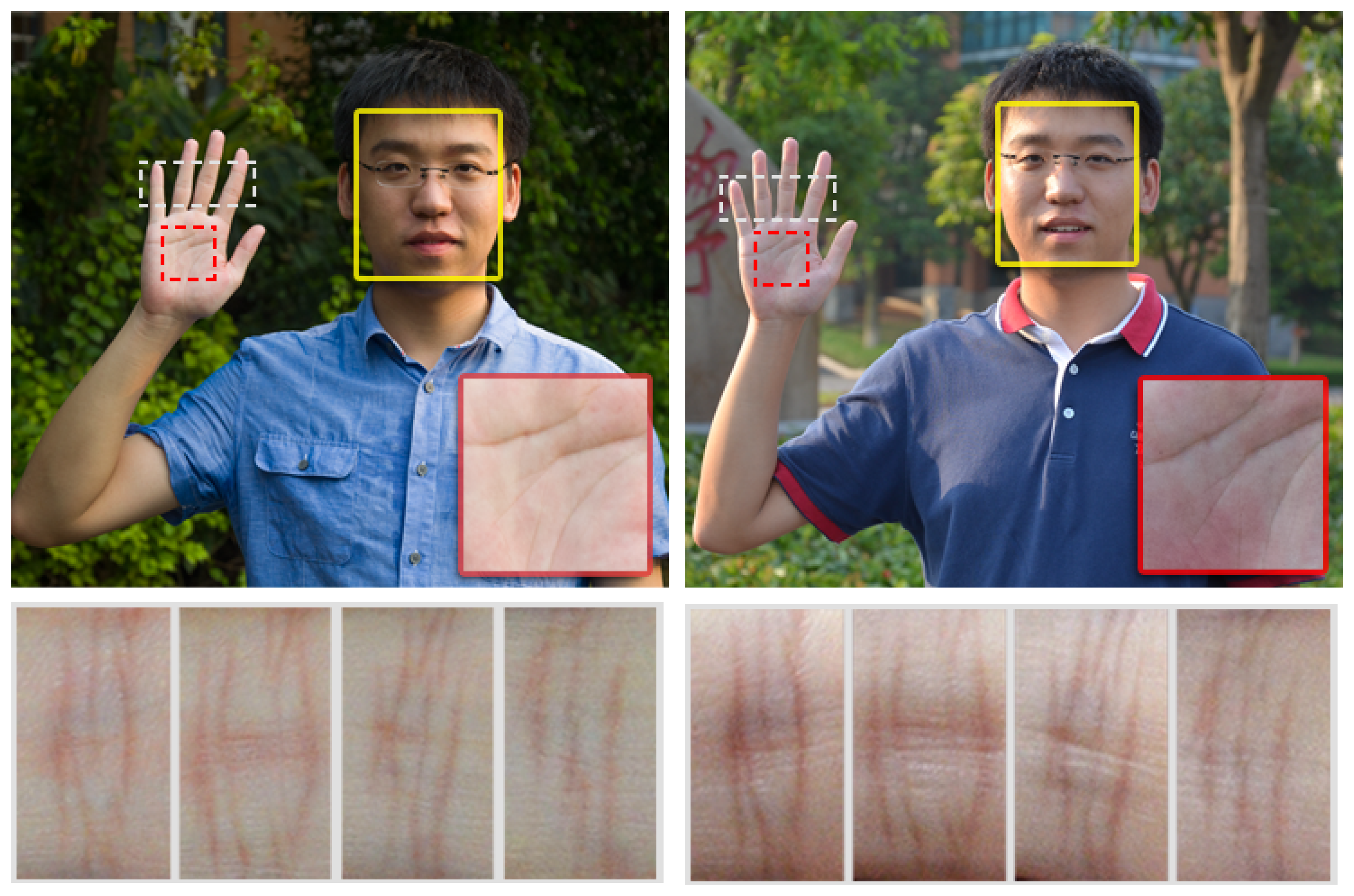
Existing portable, camera-based biometric systems utilize different biometric features. One popular stream is face recognition [1–5]. However, as demonstrated in the yellow boxes of Figure 1, the illumination cast on the faces can vary significantly. Besides, the facial expression and the aging factor of the subject further complicate the recognition. Many systems make various assumptions about the acquisition condition to ease the problem.
Another stream focuses on hand biometrics, including finger print, palm print, hand geometry, outer finger knuckle print (FKP) and inner knuckle print (IKP). This stream has received increasing attention recently, due to its user acceptability, hygienic concerns and easy self-positioning. Unfortunately, existing solutions remain quite limited. Finger print recognition [6] relies strongly on the quality of acquired images. High-quality image acquisition using a tailored high-resolution camera or scanner may be required. When using an ordinary camera for acquisition, sometimes only the crease structure of the palm print [7–10] (red boxes in Figure 1) can be extracted, which is insufficient for authentication purpose. Hand geometry features [11–13] also cannot uniquely identify a person's hand. These are usually combined with other biometric features. FKP recognition [14–18] is easily interfered by posture variation, and hence, a tailored device is usually required for achieving higher accuracy. On the other hand, IKP (the dashed white boxes in Figure 1), where the patterns are formed even before being born and determined by genes [19], is located on our fingers (geometrically close to cylinders). Its structure is clear and rich for uniquely identifying a subject. These properties allow IKP recognition to be valid under low-quality image acquisition, uncontrolled lighting conditions and positioning, and hence, it is promising as an alternative or supplement to other recognition measurements. Therefore, in this paper, we focus on IKP recognition.
Existing methods for IKP-based recognition can achieve high recognition accuracy (with an equal error rate (EER ) < 2.4%) under calibrated acquisition conditions [12,20–24]. However, the robustness of these methods under uncontrolled acquisition environments is questionable, mainly due to the following three issues.
Low-quality image: Ordinary cameras on portable devices frequently introduce different noises when they are utilized to capture small image regions. As a result, the IKP structure in the image region is blurry, noisy and hard to extract.
Illumination invariance: Illumination conditions are normally out of our control in our daily life. Changes in illumination lead to non-monotonic transformation of the intensity value and contrast, which may, in turn, lead to the weakening of important structures and magnifying the unwanted ones.
Deformation tolerance: The flexible hand orientation would inevitably introduce two kinds of deformation due to the changes of posture and perspective viewing. Such deformations can significantly reduce the recognition accuracy.
In this paper, we propose a novel IKP recognition method that can operate in uncontrolled lighting conditions and that meets the more flexible hand orientation requirement. The illumination invariance is achieved by designing a novel feature detector, which can identify the major IKP structures well, while effectively suppressing the unwanted features (generated under uncontrolled acquisition environments) that may confuse the recognition and decrease the accuracy. The more flexible orientation requirement of our hands may introduce deformation due to illumination variance, perspective viewing and the change of posture. Deformation tolerance is achieved by applying a new structure-based context descriptor on our feature map. A block-based diagram is designed to reflect a rough local structure and to handle the aliasing problem due to the discrete nature of blocks and cells. Besides, a matching scheme is designed to perform histogram matching along both the orientation and the magnitude dimensions for revealing the true distance. Even though we only demonstrate the application of our method on IKP recognition, the proposed method is generic enough to be applicable to other applications, such as image quality assessment [25–27] and image retrieval [28].
As there are no public IKP databases available for benchmarking purpose, we built two databases, DB-1 and DB-2, corresponding to the calibrated and uncontrolled acquisition environment, respectively. Our experimental results show that, under similar acquisition environments (DB-1), our method can achieve comparable performance with state-of-the-art methods. On the other hand, when the acquisition environment is uncontrolled (DB-2), our method outperforms the state-of-the-art methods significantly. A high and stable recognition accuracy rate is achieved. Moreover, in the experiments, our method can tolerate sufficiently large deformation, and hence, the orientation of users' hands can be more natural during the acquisition. Our contributions can be summarized as follows.
A novel illumination-invariant IKP feature extraction method taking both local and global information into account, which can highlight the major structures, while simultaneously suppressing the unwanted structure, hence remaining valid under uncontrolled illumination conditions.
A novel matching algorithm that employs our structure-context descriptor to represent the structure and tolerate deformation, hence remaining valid under the more flexible and natural orientation of our hands.
The rest of this paper is organized as follows. Section 2 presents related work in the field of palm print, FKP and IKP. An overview of our system is given in Section 3. Section 4 describes the proposed illumination-invariant IKP feature extraction method. In Section 5, the deformation-tolerant matching algorithm is presented. The experimental results are reported in Section 6. The conclusion is drawn in Section 7.
2. Related Works
IKP recognition has only been introduced to biometric technology for a few years, but the methods for FKP and palm print may be also applicable for IKP, as all of them have similar line patterns. Currently, there have been some works that attempted to achieve robustness for illumination and deformation to some extent. We can classify these works into three categories.
A group of works were particularly designed for illumination robustness. Among them, the code-based approaches are popular, including CompCode [14,29], Oridinal Code [30], RLOC [31], phase code [16] and Riesz transforms [32]. However, the code maps in these methods seem likely to become unreliable in smooth regions when the illumination is varied nonlinearly. The local feature extraction approach is another research direction, including local binary pattern (LBP) [23,33,34], SIFT [35–37], phase congruency [16] and the magnitude of CompCode [14]. Nevertheless, as for SIFT, since IKP is usually composed of several line segments with few intersections, the features detected by SIFT are usually unreliable. As for LBP, it is sensitive to random noise and non-monotonic illumination variation, which often exist under an uncontrolled acquisition environment. The magnitude of CompCode is influenced by non-uniform illumination, since it is based on Gabor filtering, which is affected by the contrast values. As for phase congruency, although it is proposed to be invariant to illumination and can extract the major structures under different illumination, it also easily over-strengthens the unwanted structures under complex illumination. Therefore, currently we can hardly find any local feature extraction approaches that can reliably capture the IKP structures under different illumination conditions. Recently, some subspace methods have been employed to obtain the key structures by reducing the data dimension, including PCA [22,38] and LDA [39]. However, the capability of these methods to handle illumination and deformation is quite limited.
Another stream of works is focused on deformation tolerance. Most works are targeted at handling small deformations [15,17,18,21,40]. For example, Li et al. [21] proposed applying the Hausdorff distance, since it is an effective way to measure shape similarity and can take the deformation into account well. However, it has the risk of finding the wrong matches, since the pixel-based descriptor (e.g., position) may not be sufficient to correctly reflect the real structures. For example, one image containing two close lines and the other containing a single line would be considered very similar. There also some works attempting to handle pose invariance, by applying BLPOC [15,18], the reconstruction of homograph matrix [40], the reconstruction of the affine transformation [18] and image-based reconstruction [17]. However, BLPOC can only achieve translation invariance when images are captured in the same illumination, since it is sensitive to the change of illumination. The reconstruction of the homography matrix or the affine transformation matrix has the risk that the corresponding feature points may be unreliable, which quite possibly happens in IKP recognition, since IKP usually lacks valid feature points. Image-based reconstruction is a quite robust method, but it relies on a complete training database. However, this may be not so practical, since it may need enormous samples to cover all possible cases.
The last category collects the methods based on empirical models. For example, based on the prior knowledge that the IKP structure is usually a group of straight lines, Michael et al. [20] proposed to apply the ridgelet transform to extract IKP line features. Based on the prior knowledge that almost all of the IKP structure is vertically distributed, Li et al. [21] proposed applying a Radon transform to extract the line features, and Liu and Yan [41] proposed extracting the structure in the vertical orientation only. However, either ridgelet or Radon transform are influenced by illumination, since they do the statistics on intensity values. On the other hand, inspired by these works, we also integrated prior knowledge in our method and create a new model to strengthen the vertical structure and to suppress the horizontal structure.
Overall, existing methods attempted to achieve illumination robustness and deformation tolerance in a small range. Unfortunately, they are still far from satisfactory for the situation of uncontrolled acquisition environments.
3. System Overview
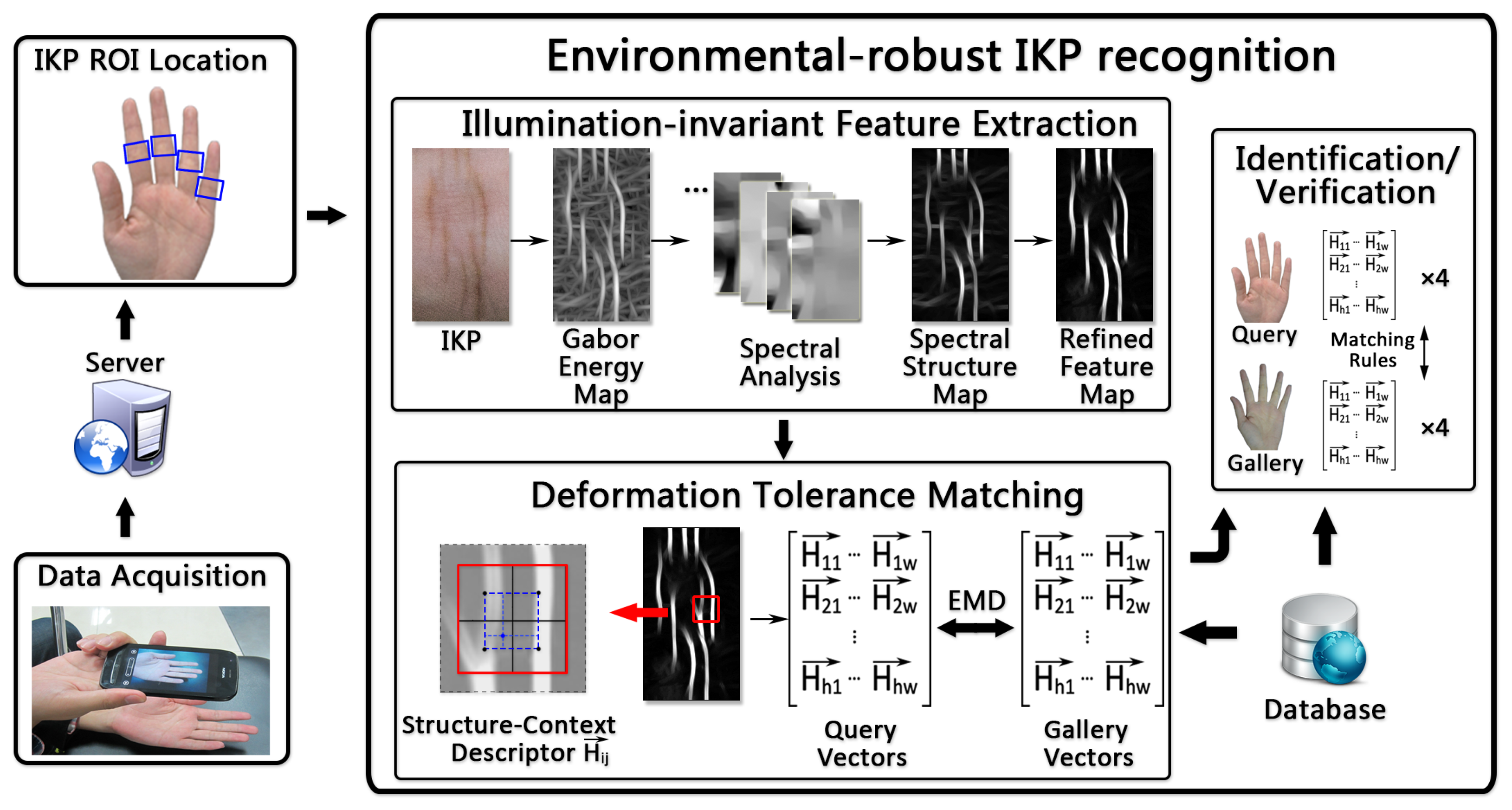
Figure 2 shows the pipeline of the proposed system, which is composed of three steps: data acquisition, ROI location, IKP recognition (including feature extraction and matching and hand identification/verification).
3.1. Data Acquisition
The hand images used in our system are acquired by ordinary cameras equipped on portable devices. We describe the uncontrolled acquisition environment as follows. First, the lighting condition and the camera exposure have no special restrictions, but there should be no severe over-exposure or under-exposure, as little recognizable structure information can be acquired in these two conditions. Second, the hand is asked to be naturally stretched out without any occlusion among the fingers. Third, the acquired image should cover the whole palm, and the palm should occupy the image as much as possible. Fourth, the background contains no color that is similar to the skin color. According to our experience, these restrictions are not tough and are easily satisfied for most portable devices in practice. The acquired hand images are then sent to a server via a wireless network.
3.2. ROI Extraction
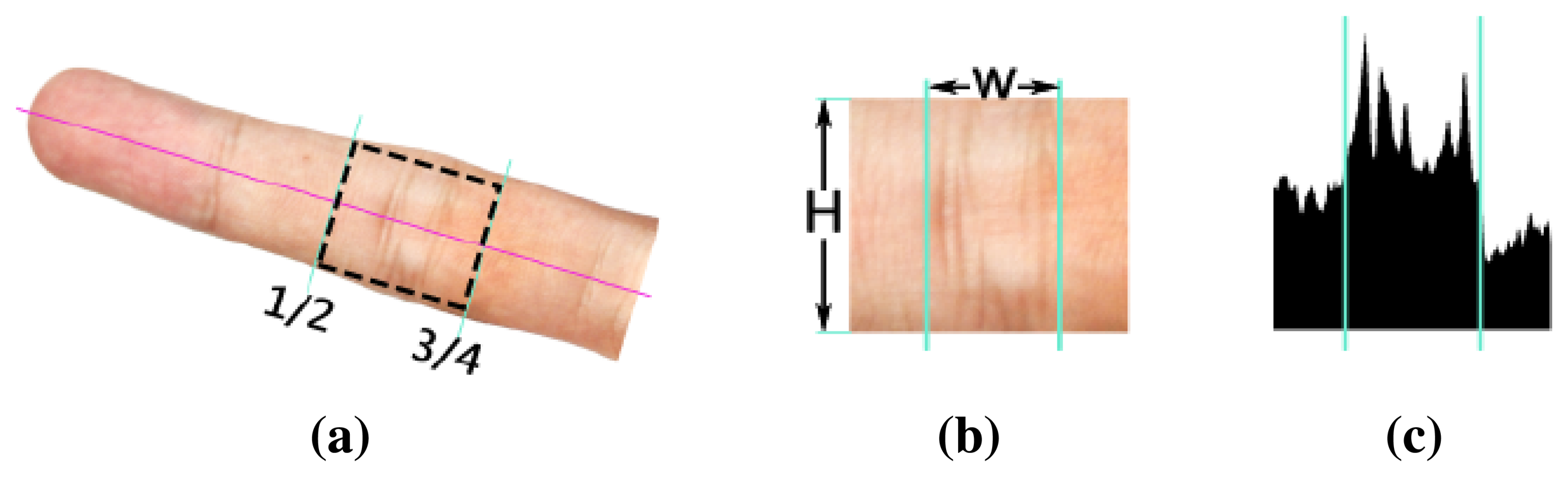
We then extract the regions of interest (ROIs) of IKP from the images. In our system, we employ the IKP ROIs in the middle nodes of four fingers, except for the thumb (Figure 2), since their structures are relatively rich and clear. We first automatically separate the hand from the background by applying an integrated model of SCMand CASM [11]. Then, motivated by [12], the coarse ROI can be extracted based on the prior knowledge of the IKP geometry that the middle node is located between 1/2 to 3/4 the length of a finger (Figure 3a). This coarse ROI is rotated to a standard orientation by aligning the finger axis to the horizontal direction and resized to a unified scale according to a predefined height H (250 pixels in our implementation) (Figure 3b). Finally, the ROI is located using Radon projection, which covers the most informative areas in the projected result (Figure 3c) with a predefined length W (140 pixels in our implementation). As a result, all of the IKP ROI images are normalized to the same scale, rotation and translation.
3.3. IKP Recognition
To operate under the uncontrolled acquisition environments of portable devices, we propose an illumination-invariant feature extraction method tailored for IKP images. Furthermore, we propose a novel matching algorithm to accurately represent the structure and to tolerate deformations. We will detail them in Sections 4 and 5, respectively. As the IKP of each finger is highly unique and can be employed as a distinctive biometric identifier, one perfectly matched IKP is sufficient to authenticate a person. There is no need to match all four IKPs in an acquired image. For robustness, in our experiments, we take the following rules as our authentication criteria: two hand images are recognized as a matched pair when there is a perfect IKP matching pair or at least two fairly matched pairs. A perfect matching pair is defined as the case that the matching error is less than 0.8T, where T is the threshold and experimentally set as 0.41 in our work.
4. Illumination-Invariant Feature Extraction
Under uncontrolled acquisition environments, illumination variations easily lead to non-monotonic transformations of the gray scale, loss of details and ambiguous structures, making extracting features in an IKP image a difficult task. The aim of our method is to accurately extract the main features of an IKP image while eliminating the unwanted features that complicate the matching and recognition.
4.1. Local Feature Analysis
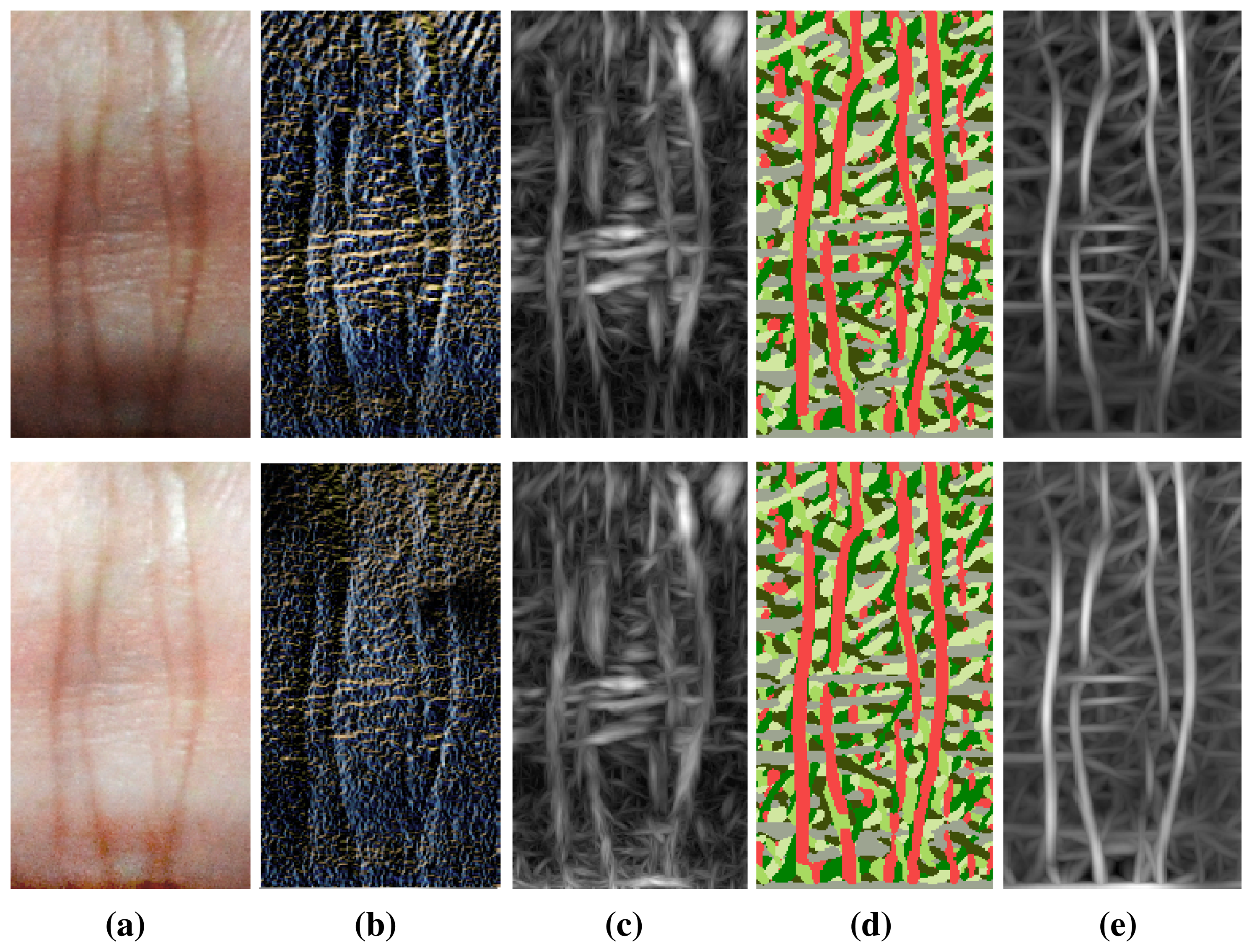
In biometric systems, local feature detection methods have been extensively investigated. Figure 4 shows the results of some state-of-the-art local detectors aiming at illumination robustness, including local binary pattern (LBP) [23], phase congruency (PC) [29], a competitive coding scheme (CompCode) [16] and the magnitude map of CompCode [14]. In the IKP images (Figure 4a), there are a lot of fine lines around the main structures of the IKP, and they exhibit different characteristics under two different illumination conditions. Besides eliminating these unwanted structures, we have to avoid bringing in false structures caused by different illumination.
In the results of the LBP method (Figure 4b), a lot of week structures are detected with the main IKP structures, making robust matching of the IKP images challenging. This is because the LBP method is based on intensity distance, but the intensity distances for fine lines are locally large enough to be detected as features, especially under low lighting conditions. The PC method was originally proposed to extract the major structures under low contrast by searching the consistent phase regions. As a trade-off, PC often incorrectly strengthens weak structures at the same time, which is particularly serious for IKP images, as IKP images usually contain a lot of ambiguous structures, such as mutable creases and blood and meridian vessels. As shown in Figure 4c, these unwanted structures are also detected by PC. The CompCode method was proposed to obtain orientation information, so as to reveal the stable structure information under different illuminations. It performs well on regions containing major structures. However, the orientation values become unreliable and random on the smooth regions, since in these regions, their responses to different orientations are small, similar and, hence, vulnerable to noises, as shown in Figure 4d. Among these methods, it is observed that the magnitude of CompCode (Figure 4e outputs the best results, where the Gabor filtering is employed for the local statistics. It can reveal the local structures, while tolerating the monotonic illumination variation and small deformations. Hence, we adopt the CompCode magnitude map as our basic feature map, which is generated by:
Although the magnitude maps of CompCode achieve good results for IKP images, it is noticeable that lots of weak and false structures still exist, which will greatly affect the accuracy of the following matching and recognition. As shown in Figure 4e, these unwanted features are widely distributed in the map, and some of them may have high energy values. In this case, it is difficult to use a local filter to remove these unwanted structures in the magnitude map.
4.2. Global Feature Extraction
To extract the main structures of IKP while suppressing the unwanted structures in the magnitude map of CompCode, we propose an efficient global-based algorithm. Inspired by the global detector proposed in [42], we first formulate the salient structure extraction problem as a partition of a weighted graph with the main structures of IKP as boundaries and then apply a spectral clustering algorithm to solve it. In this way, most false structures and weak structures caused by illumination variation across the main structures can be eliminated.
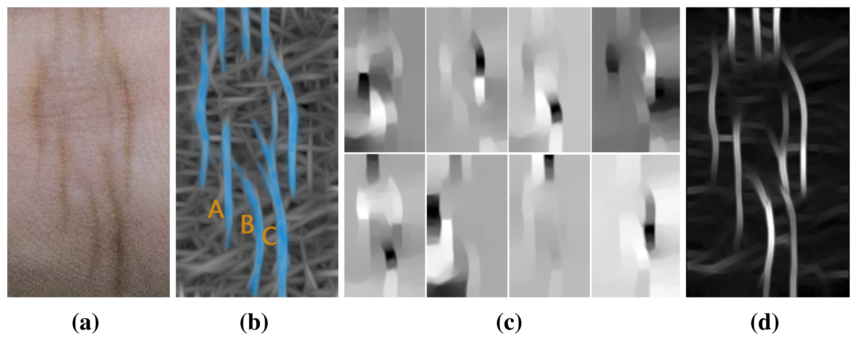
It is observed that in the magnitude map of CompCode, the whole image can be divided into several regions by the main structures of IKP, as shown in Figure 5b. To that end, we can represent the map as a weighted graph, where every pixel corresponds to a node of the graph, and the relationship between two pixels corresponds to a weighted edge of the graph. The weights are calculated by a similarity matrix, which will be introduced later. Thus, to find the main IKP structure, we should find an optimal graph partitioning solution that ensures that pixels in each region of the partitioning solution have a high degree of affinity.
To reflect the degree of affinity between two pixels, we employ the idea of normalized cuts [43], based on spectral graph theory, to construct our detector. Its core idea is to construct a similarity matrix W and a Laplace matrix D − W to reflect the characteristics of the map and to obtain an approximate solution of multi-normalized cuts through solving a linear system. Then, we can construct the most salient features from the first several eigenvalues.
We construct a probability distribution of the boundaries of the map and define P as the probability of the boundaries. Then, we define the similarity matrix W as:
Thus, we can calculate the n+1 smallest eigenvalues 0 = λ0 ≤ λ1 ≤ … ≤ λn and their corresponding eigenvectors {v0, v1,…, vn}, which can describe the distribution information of IKP main structures, by solving the following linear system:
We employ a standard spectral clustering algorithm to segment the graph, and the segmented boundaries embody the main structures of the IKP. For this purpose, we first calculate the directional derivative of n major eigenvectors to extract these structures and then compute the weighted summation of the structures:
Although Ps can provide the energy values for six orientations, generally, one dominant orientation is enough, since most of the IKP structures are straight lines. Hence, in our work, we use the dominant orientation and its energy to present the structures of IKP. We define the dominant orientation using a competitive rule as follows.
Figure 5d shows the competitive energy map after performing our algorithm. Compared with Figure 4e, it is observed that most salient features are preserved, while a lot of weak and false structures are removed.
4.3. Refinement Using Empirical Model
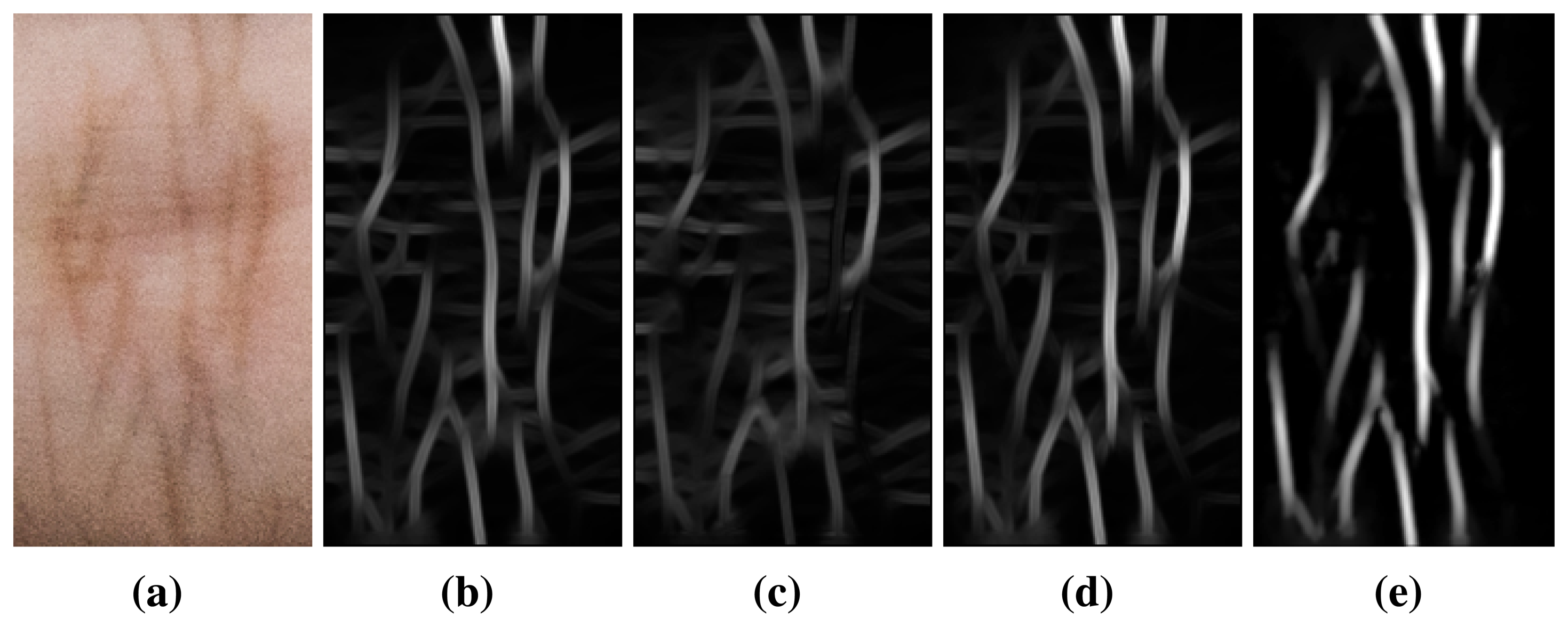
Our global feature detection can remove most unwanted structures, but there are still some weak structures in the energy map, as shown in Figures 5d and 6b. After carefully studying the results, we find that most of these remaining weak features are fingerprint lines and small subcutaneous blood vessels in the horizontal direction, while the majority of reliable IKP structures are in the vertical direction. According to this observation, we refine our results by suppressing the weak structures in the horizontal direction while enhancing the structures in the vertical direction.
From Equation (6), we can obtain the probability distribution of IKP structures in all directions. We assume that when θ = 0°, 30°, 150°, the Ps mainly represents the characteristics in horizontal directions, while when θ = 60°, 90°, 120°, the Ps mainly represents the characteristics in vertical directions. In this regard, we refine our result using the following equation:
We employ a vector A to obtain a uniform feature representation for each pixel, which is composed of six components corresponding to the six orientations. After initialization, only the refined competitive energy values are stored in the vector, Axy [θ*/30°] = Pr(x, y). The other five components are set to zero.
5. Deformation-Tolerant Matching Algorithm
Besides illumination variance, the uncontrolled acquisition mode would inevitably introduce deformations in the captured IKP images. Hence, deformation tolerance is another key issue that should be addressed for the success of an IKP recognition system.
The deformations can be classified into two categories: global deformations and local deformations. Global deformations are mainly caused by different hand postures, and we utilize the prior knowledge of the finger's geometry to obtain the coarse global normalization for the IKP ROI to address these posture-induced deformations. Please refer to Section 3 for details. In the following, we focus on local deformations, including non-rigid deformations and shear and perspective transformations.
It is observed that the most local deformations are limited to a small region, as illustrated in Figure 7. In this regard, local statistics methods, such as the block diagram in HOG [44] or the log-polar diagram in shape context [45], should be sufficient to tolerate this kind of local deformation. On the other hand, sophisticated image mapping methods for dealing with big deformations, such as SIFT-based matching algorithms [35-37] or PTA [34], may fail with IKP images, as the IKP structures are often so simple that their eigenvectors are quite similar and lack uniqueness. Specifically, SIFT may fail to find sufficient reliable feature points, while PTA would easily find the wrong matched points. Therefore, we propose a new structure-context descriptor (SCD) performing local statistics on our feature maps to handle these local deformations.
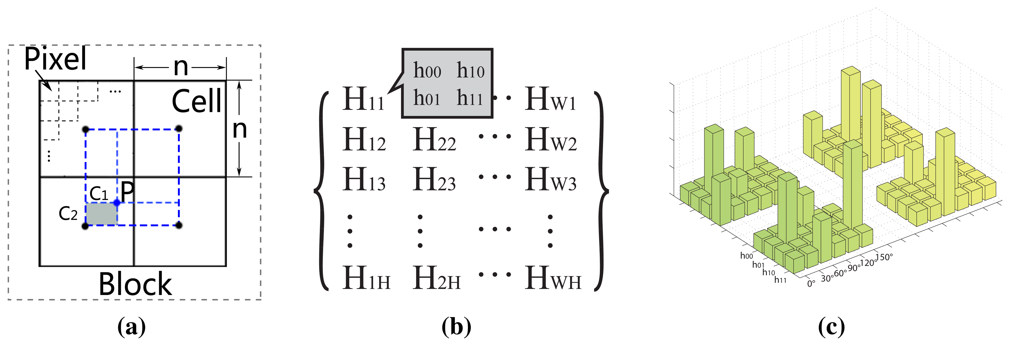
Our descriptor is designed to reflect the structure context in the neighborhood well, while tolerating small local deformation. Actually, different diagrams can be used for our descriptor [44,45]. However, to simplify the computation, motivated by HOG [44], we apply the block diagram to our feature map, as shown in Figure 8a. For each cell, we summarize all of the feature vectors of the pixels in this cell to reflect its rough structure. In this way, for one cell, the feature vectors of pixels are accumulated, and this leads to its nature of deformation tolerance. In other words, the degree of deformation tolerance is implicitly defined in the cell size. However, due to the discrete nature of the cell and block, an aliasing problem inevitably occurs. To circumvent this problem, as shown in Figure 8a, we first assign the value of each pixel to its nearest four cell centers by bilinear interpolation; then, we broaden half of a cell along the boundary of the block, as the pixels in this extended region would also contribute to the histogram of the cell. Thus, for a block diagram, the histogram of each cell can be calculated by:
Next, we apply our SCD on our feature map, scanning the whole map by moving the block diagram from left to right and top to bottom, with a stride of 0.5n. After that, a matrix of histograms is produced to describe the feature map, as shown in Figure 8b,c.
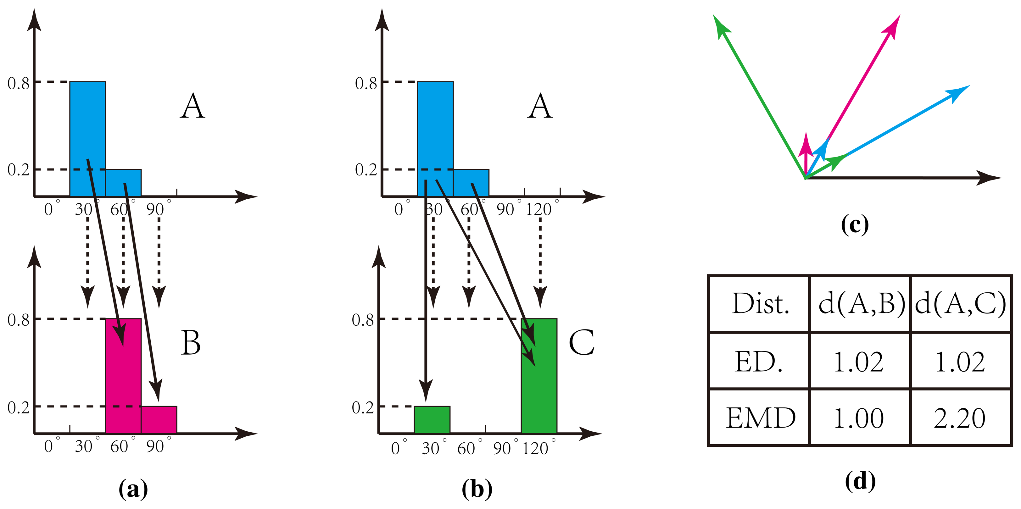
The measurement of the histogram distance for our SCD is crucial for successful recognition. Euclidean distance, however, fails to reflect the true distance. As shown in Figure 9, it is clear that histograms A (blue vector in (c)) and B (green vector in (c)) are similar, while A and C (red vector in (c)) are much more different. However, these two groups are evaluated with the same distance based on the Euclidean distance, which are indicated by the dashed lines in Figure 9a,b. To tackle this problem, we adopt the Earth mover distance (EMD) [46], in which both the orientation and energy value can be taken into account, and an optimal solution will be found by minimizing the movement cost, as indicated by the solid lines in Figure 9a,b. Thus, the EMD distance can evaluate the true distance of our histograms, as shown in Figure 9d. Therefore, the distance of two images D(S, S′) can be calculated by:
6. Experimental Results
6.1. IKP Database and the Test Protocol
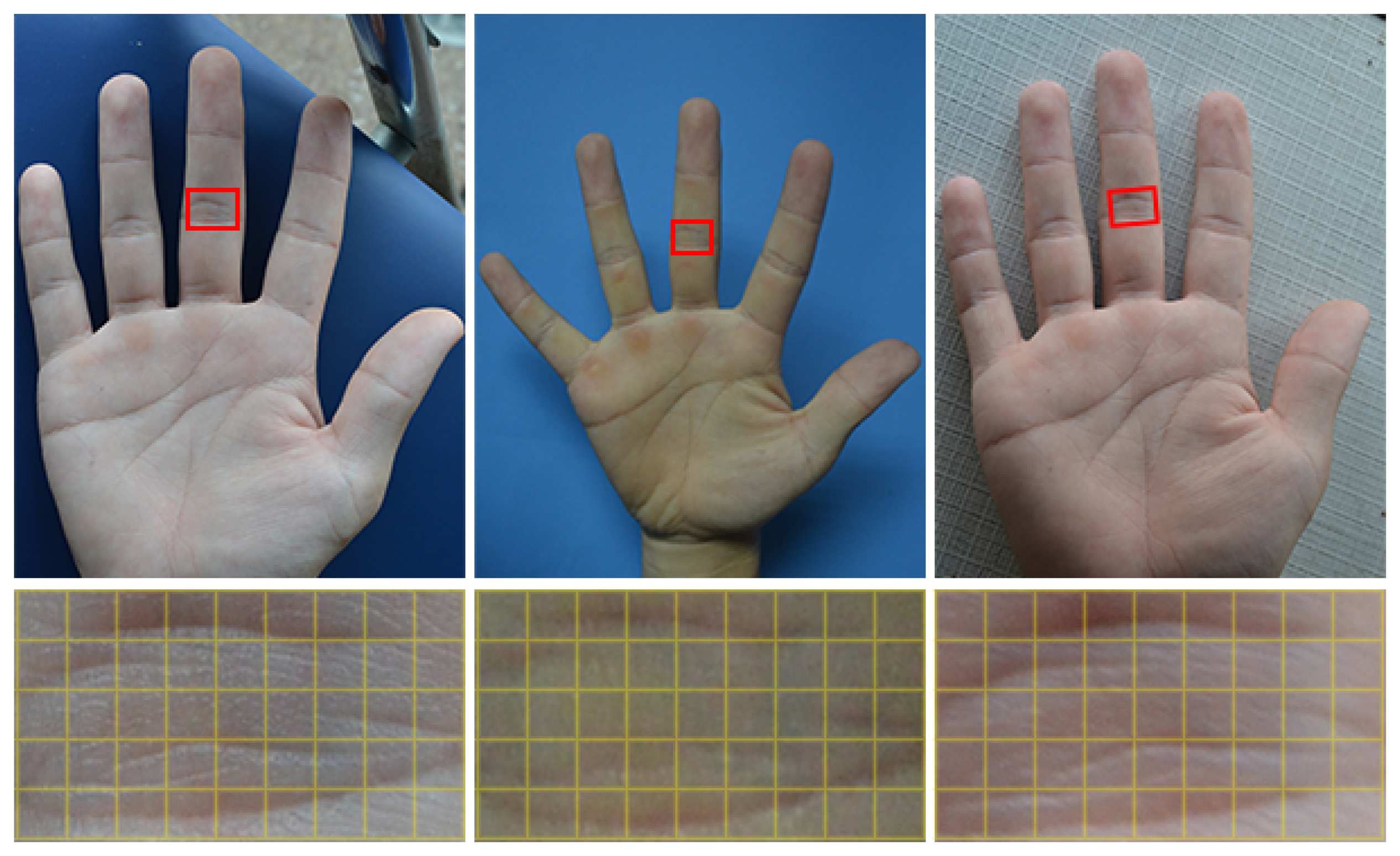
To the best of our knowledge, currently, there is no publicly available IKP database for benchmarking. To evaluate the performance of our proposed system, a specific database was built by us. Our IKP images were collected from 100 volunteers, including 60 males and 40 females. Among them, 80 subjects were 18–30 years old, and the others were 30–52 years old. For each subject, five images of each hand were captured, corresponding to each column in Figure 10. Two of them were from the same environment with similar postures (the top two rows in Figure 10), and three of them were from different real environments with relatively large variations of posture (the lower three rows in Figure 10. Thus, there are 1000 hand images and 4000 extracted ROIs available in total.
To better compare our proposed method with existing methods in terms of the robustness to illumination variance and deformation, we divided our IKP images into two groups, DB-1 and DB-2. DB-1 contains only the IKP images captured under the same environments, two images for one hand (top two rows in Figure 10), 400 images and 1600 ROIs in total. DB-2 contains the IKP images captured under different environments, four images for one hand, 800 images and 3200 ROIs in total.
We measure the performance in terms of recognition accuracy using both verification and identification modes. Generally, identification is a one-to-many comparison against all stored templates, which answers the question “Which one of N people is this person?”. In the identification experiments, the statistics, best identification rate (BIR), which is known as the rank-1 recognition rate, as well, is adopted for evaluation. Verification is a one-to-one comparison against a single stored template, which answers the question of “whether the person is whom he claims to be”. In the verification experiments, the statistics, equal error rate (EER), is adopted to evaluate the performance. EER is defined as EER = FAR when the false acceptance rate (FAR) is equal to the false rejection rate (FRR). Here, FAR = FA/(GR + FA), FRR = FR/(GA + FR), and FA, FR, GA and GR are the proportions of false acceptances, false rejections, genuine acceptances and genuine reflections, respectively. In general, the lower the EER value is, the more reliably the biometric system performs.
6.2. Comparison with Existing Methods
We compare our method with state-of-the-art methods, including ImCompCode + MagCode [14 LGIC2 [16], R-ABF [17] and local block BLPOC [18], respectively. Although these four methods are not directly proposed for IKP recognition, they are currently the most effective methods for the recognition of IKP, FKP and palm print and are targeted at achieving robustness to illumination and deformation. We conduct the experiments on DB-1 and DB-2, respectively.
Experiment on DB-1: We start from the single-ROI recognition, which means the recognition unit is a single ROI image. In this case, the identification test will be carried out 1600 times, and the verification test will be performed 1600 × 1599 times. Next, we perform integrated ROI recognition, where the final decision is made based on the four ROIs' matching results from the same hand image. In this regard, verification is processed 400 × 399 times and identification 400 times.
Table 1 illustrates the performance of all methods based on DB-1 in two modes of both single ROI recognition and integrated ROI recognition. As for single ROI recognition, note that the results of all methods are acceptable for a biometric security system, and our method has better recognition accuracy than others. The accuracy is further improved if integrated ROI recognition is applied, since three more matching results can be used for making the final decision. Table 1 proves that all of the methods are robust to the small variations of illumination and deformation.
Figure 11 illustrates the receiver operating characteristic (ROC) curves, which plot the false acceptance rate (FAR) against the genuine acceptance rate (GAR). Here, we only plot the curves for single ROI recognition, since the results for integrated ROI recognition are too close to be separated clearly. For a biometric security system, the false acceptance is usually much more unacceptable than the false rejections. Hence, for a good biometric system, its GAR value should increase very quickly against the FAR value. From Figure 11, it is noticeable that, according to the same value of FAR, our method can always achieve the highest GAR, which implies that our method has better recognition accuracy.
Experiment on DB-2: Similar to experiments on DB-1, we also carry out the single ROI and integrated ROI recognition on DB-2.
Table 2 illustrates the performance of all methods based on DB-2. As for single ROI recognition, it is obvious that the existing methods have EER values larger than 7.0, which are far from acceptable for a biometric security system. Even for the integrated-ROI recognition, their results are larger than 2.26, which is also unacceptable. However, our method can obtain 3.07 and 0.74 for single ROI and integrated ROI recognition, which should be quite acceptable for a biometric system.
We found that the method of local block BLPOC has the worst result. That is because the features extracted by BLPOC are not robust to the contrast variations caused by illumination or deformation. ImCompCode improved the original CompCode scheme by proposing an evaluation method for detecting the “plane” pixels and removing them from orientation coding. However, it usually fails under complex illumination, since sharp edges may be smoothed and weak edges are strengthened. LGIC2 proposes to combine multiple features, including ImCompCode, phase congruency and phase code. Unfortunately, it is also unstable under complex illumination and easily strengthens the unwanted structures. R-ABFaims at solving the problem of posture deformation, but it cannot handle illumination variances and requires a database that should cover most of the possible postures. However, our database only contains five postures for each hand, and it is difficult to construct a database that fulfills the requirement of R-ABF.
In our work, we propose a tailored feature extraction scheme for IKP images, which can almost operate under different illumination. Figure 12 illustrates the receiver operating characteristic (ROC) curves for single ROI and integrated ROI recognition, respectively. According to the same value of FAR, our method can always achieve a much higher GAR than others, which implies that our method has better recognition accuracy.
6.3. Further Discussions
6.3.1. Threshold Determination
For a biometric security system, a unified reliable threshold is necessary for recognition. Unfortunately, there is no convincing method to determine the threshold in this kind of system. Thresholds corresponding to EER have been used in some cases for this purpose. However, as shown in Figure 13, thresholds on EER are unstable and varied largely under the two databases. Considering that the target threshold is used for separating the matched and unmatched cases, thresholds corresponding to the minimum mismatching should approximate the true threshold. We define the minimum mismatching as the fewest false recognitions rate (FFRR), calculated as FFRR = min [(FA + FR)/(GA + GR + FA + FR)], where FA, FR, GA, GR indicate false acceptance, false rejection, genuine acceptance and genuine rejection, respectively. Figure 13 shows that thresholds for the FFRR are much more stable under the two databases compared to the thresholds for EER. Hence, in our system, we apply the threshold of the FFRR for determining matching or not. In practice, we set the threshold to 0.41.
6.3.2. Tolerance to Deformation
To validate the deformation tolerance of our method, we prepare the test samples in two ways: changes in posture (the top row in Figure 14) and viewpoints (Figure 15 and the lower three rows in Figure 14).
As for the deformation due to changes in posture, we can find that once our loose restrictions on acquisition (specified in Section 3.1) are satisfied, almost all of the posture variations can be well tolerated by our system. The first row in Figure 14 shows some challenging cases by changing the postures, and all of them can be successfully recognized by our method. As for the deformation due to the change of viewpoints, we use five concentric spheres to approximate the variation of viewpoints, as shown in Figure 15. The radius for the smallest sphere is defined as r, which is actually the distance between the hand and camera, and it is determined once the hand can almost fill the whole image. The radii for the other spheres are defined as 1.2r, 1.4r, 1.6r and 2.0r, indicated as the five red points on the x axis. Moreover, we further sample the viewpoints on each sphere uniformly with a step of 15 degrees. In Figure 15, we only show the uniform sampling viewpoints for the sphere with 1.2r for the purpose of clear visualization. The two sequences of black and blue points indicate that the viewpoints changed from left to right and from bottom to top, respectively. Based on our experimental results, our method is invariant to the viewpoints on the x axis, and it can endure 30° (yellow region in Figure 15), referring to the x axis. Here, we define the x axis as the vector going through the center of the hand (the root of the center finger) and facing the hand plane perpendicularly. Figure 14 shows some challenging IKP images that can be tolerated by our method, demonstrating the capability of our method to tolerate deformations.
6.3.3. Tolerance to Illumination Variation
Tolerance to illumination variation plays a crucial role in our biometric recognition system. In order to measure the performance of our method under different illumination, we capture samples under several scenes and analyze the matching distances. We first change the shutter speed to simulate the illumination variation in the same scene. Figure 16 shows part of the captured images with the shutter speed varied from 1/800 s to 1/20 s. Note that our method has decent robustness to the exposure variation, unless the structures of the IKP are permanently lost due to overexposure or underexposure (Figure 16a,h).
Next, the influence of ambient light variation is considered in the following experiment. Since ambient light is composed of complex direct light and reflected light, it is difficult to quantize. We utilize a few typical scenes to simulate different settings of ambient light and evaluate the tolerance of our method to them. Figure 17 shows that our system performs robustly under different scenes, which implies that our method has decent tolerance under random illumination.
6.3.4. Time Performance
We implement our system, as well as the other four competitors on a PC with Intel Core i7 4790 K 4.4 GHz CPU with eight threads, 16 GB RAM and the Microsoft Windows 7 64-bit operating system. Table 1 shows that all of the methods achieve high efficiency, although our method is a little slower than the others. Meanwhile, our method can maintain high efficiency even under an enormous database, since the features of the training images are extracted offline and only the matching algorithm is computed online, which is so efficient due to parallel computation (generally < 50 ms for one thousand times).
7. Conclusions
We propose a robust IKP matching and identification method for biometric authentication purposes. The proposed method can survive under uncontrolled lighting conditions, noisy and blurry image acquisition, as well as deformation due to hand orientation and perspective projection. Hence, users of the biometric authentication system can be relieved from the careful planning of the acquisition environment and the unnatural hand orientation during the capture. The proposed method outperforms state-of-the-art biometric feature recognition methods when the acquisition environment is challenging. Our current algorithm still requires a remote server for execution due to the relatively high computational cost. We believe that, by redesigning and simplifying the algorithm, the method should be lightweight enough to be executed on portable devices without a remote server.
Acknowledgments
This work was supported by the funding from Guangzhou Novo Program of Science and Technology (Grant No. 0501-330), the National Natural Science Foundation of China (Grant No. 61103120,61472145,61272293,61233012), the Research Fund for the Doctoral Program of Higher Education of China (Grant No. 20110172120026), the Shenzhen Nanshan Innovative Institution Establishment Fund (Grant No. KC2013ZDZJ0007A) , the Shenzhen Basic Research Project (Project No. JCYJ20120619152326448), the Natural Science Foundation of Guangdong (Project No. S2013010014973) and a grant of RGC General Research Fund (Grant No. 417913).
Author Contributions
Xuemiao Xu: Propose the main ideas and design the whole system. Qiang Jin: Develop the feature extraction algorithm and the structure-context descriptor. Le Zhou: Perform the experiments and help to implement the algorithms. Jing Qin: Propose parts of the ideas and help to optimize the algorithms. Tien-Tsin Wong: Polish the ideas and paper writing. Guoqiang Han: Polish the ideas and guide the whole development process.
Conflicts of Interest
The authors declare no conflict of interest.
References
- Ren, J.; Jiang, X.; Yuan, J. A complete and fully automated face verification system on mobile devices. Pattern Recognit. 2013, 46, 45–56. [Google Scholar]
- Kahraman, F.; Kurt, B.; Gokmen, M. Robust face alignment for illumination and pose invariant face recognition. Proceedings of 2007 IEEE Conference on Computer Vision and Pattern Recognition (CVPR'07), Minneapolis, MN, USA, 17–22 June 2007; pp. 1–7.
- Wolf, L.; Hassner, T.; Maoz, I. Face Recognition in Unconstrained Videos with Matched Background Similarity. Proceedings of 2011 IEEE Conference on Computer Vision and Pattern Recognition (CVPR'11), Providence, RI, USA, 20–25 June 2011; pp. 529–534.
- Arandjelovic, O.; Cipolla, R. Achieving robust face recognition from video by combining a weak photometric model and a learnt generic face invariant. Pattern Recognit. 2013, 46, 9–23. [Google Scholar]
- Ho, H.T.; Gopalan, R. Model-Driven Domain Adaptation on Product Manifolds for Unconstrained Face Recognition. Int. J. Comput. Vis. 2014, 109, 110–125. [Google Scholar]
- Hrechak, A.; McHugh, J. Automated fingerprint recognition using structural matching. Pattern Recognit. 1990, 23, 893–904. [Google Scholar]
- Jia, W.; Hu, R.; Gui, J.; Zhao, Y. Palmprint recognition across different devices. Sensors 2012, 12, 7938–7964. [Google Scholar]
- Han, Y.; Tan, T.; Sun, Z.; Hao, Y. Embedded palm print recognition system on mobile devices. In Advances in Biometrics; Springer: Berlin Heidelberg, Germany, 2007; pp. 1184–1193. [Google Scholar]
- Jemaa, S.B.; Hammami, M.; Ben-Abdallah, H. Biometric identification using a new direction in contactless palm print imaging. Proceedings of the International Conference of Image Processing Computer Vision and Pattern Recognition (IPCV'12), Las Vegas, NV, USA, 16–19 July 2012; pp. 883–889.
- Zhang, D.; Zuo, W.; Yue, F. A comparative study of palm print recognition algorithms. ACM Comput. Surv. 2012, 44, 520–523. [Google Scholar]
- Doublet, J.; Lepetit, O.; Revenu, M. Contact less Hand Recognition Using Shape and Texture Features, Proceedings of 2006 the 8th International Conference on Signal Processing, Beijing, China, 16–20 November 2006.
- Savič, T.; Pavešić, N. Personal recognition based on an image of the palmar surface of the hand. Pattern Recognit. 2007, 40, 3152–3163. [Google Scholar]
- Kanhangad, V.; Kumar, A.; Zhang, D. Contactless and pose invariant biometric identification using hand surface. IEEE Trans Image Process. 2011, 20, 1415–1424. [Google Scholar]
- Zhang, L.; Zhang, L.; Zhang, D.; Zhu, H. Online finger-knuckle-print verification for personal authentication. Pattern Recognit. 2010, 43, 2560–2571. [Google Scholar]
- Zhang, L.; Zhang, L.; Zhang, D.; Zhu, H. Ensemble of local and global information for finger knuckle print recognition. Pattern Recognit. 2011, 44, 1990–1998. [Google Scholar]
- Zhang, L.; Zhang, L.; Zhang, D.; Guo, Z. Phase congruency induced local features for finger-knuckle-print recognition. Pattern Recognit. 2012, 45, 2522–2531. [Google Scholar]
- Gao, G.; Zhang, L.; Yang, J.; Zhang, L.; Zhang, D. Reconstruction based finger-knuckle-print verification with score level adaptive binary fusion. IEEE Trans. Image Process. 2013, 22, 5050–5062. [Google Scholar]
- Aoyama, S.; Ito, K.; Aoki, T. A finger-knuckle-print recognition algorithm using phase-based local block matching. Inf. Sci. 2014, 268, 53–64. [Google Scholar]
- Rodriguez, R. Biometric Identification by Dermatoglyphics. Proceedings of 1996 International Conference on Image Processing, Lausanne, Swizerland, 16–19 September 1996; pp. 319–322.
- Michael, G.K.O.; Connie, T.; Jin, A.T.B. An innovative contactless palm print and knuckle print recognition system. Pattern Recognit. Lett. 2010, 31, 1708–1719. [Google Scholar]
- Li, Q.; Qiu, Z.; Sun, D.; Wu, J. Personal identification using knuckleprint. In Advances in Biometric Person Authentication; Springer: Berlin Heidelberg, Germany, 2005; pp. 680–689. [Google Scholar]
- Nanni, L.; Lumini, A. A multi-matcher system based on knuckle-based features. Neural Comput. Appl. 2009, 18, 87–91. [Google Scholar]
- Liu, M.; Tian, Y.; Ma, Y. Inner-Knuckle-Print Recognition Based on Improved LBP. In Proceedings of the 2012 International Conference on Information Technology and Software Engineering; Springer: Berlin Heidelberg, Germany, 2013; Volume 212, pp. 623–630. [Google Scholar]
- Liu, M.; Tian, Y.; Li, L. A new approach for inner-knuckle-print recognition. J. Vis. Lang. Comput. 2014, 25, 33–42. [Google Scholar]
- Wang, Z.; Bovik, A.C.; Sheikh, H.R.; Simoncelli, E.P. Image quality assessment: From error visibility to structural similarity. IEEE Trans. Image Process. 2004, 13, 600–612. [Google Scholar]
- Sampat, M.P.; Wang, Z.; Gupta, S.; Bovik, A.C.; Markey, M.K. Complex wavelet structural similarity: A new image similarity index. IEEE Trans. Image Process. 2009, 18, 2385–2401. [Google Scholar]
- Zhang, L.; Mou, X.; Zhang, D. FSIM: A feature similarity index for image quality assessment. IEEE Trans. Image Process. 2011, 20, 2378–2386. [Google Scholar]
- Smeulders, A.W.; Worring, M.; Santini, S.; Gupta, A.; Jain, R. Content-based image retrieval at the end of the early years. IEEE Trans. Pattern Anal. Mach. Intell. 2000, 22, 1349–1380. [Google Scholar]
- Kong, A.; Zhang, D. Competitive Coding Scheme for Palmprint Verification. Proceedings of the 17th International Conference on Pattern Recognition (ICPR 2004), Cambridge, UK, 23–26 August 2004; Volume 1, pp. 520–523.
- Sun, Z.; Tan, T.; Wang, Y.; Li, S.Z. Ordinal Palmprint Represention for Personal Identification. Proceedings of IEEE Computer Society Conference on Computer Vision and Pattern Recognition (CVPR 2005), San Diego, CA, USA, 20–25 June 2005; Volume 1, pp. 279–284.
- Jia, W.; Huang, D.; Zhang, D. Palmprint verification based on robust line orientation code. Pattern Recognit. 2008, 41, 1504–1513. [Google Scholar]
- Zhang, L.; Li, H. Encoding local image patterns using Riesz transforms with applications to palm print and finger-knuckle-print recognition. Image Vis. Comput. 2012, 30, 1043–1051. [Google Scholar]
- Wang, X.; Gong, H.; Zhang, H.; Li, B. Palmprint Identification Using Boosting Local Binary Pattern. Proceedings of the 18th International Conference on Pattern Recognition (ICPR 2006), Hong Kong, China, 20–24 August 2006; Volume 3, pp. 503–506.
- Michael, G.K.O.; Connie, T.; Jin, A.T.B. Touch-less palm print biometrics: Novel design and implementation. Image Vis. Comput. 2008, 26, 1551–1560. [Google Scholar]
- Moralesand, A.; Ferrerand, M.A.; Kumar, A. Towards contactless palm print authentication. Comput. Vis. IET 2011, 5, 407–416. [Google Scholar]
- Morales, A.; Travieso, C.; Ferrer, M.; Alonso, J. Improved finger-knuckle-print authentication based on orientation enhancement. Electron. Lett. 2011, 47, 380–381. [Google Scholar]
- Lowe, D.G. Object Recognition from Local Scale-Invariant Features. Proceedings of the Seventh IEEE International Conference on Computer Vision, Kerkyra, Greece, 20–27 September 1999; Volume 2, pp. 1150–1157.
- Ribaric, S.; Fratric, I. A biometric identification system based on eigenpalm and eigenfinger features. IEEE Trans. Pattern Anal. Mach. Intell. 2005, 27, 1698–1709. [Google Scholar]
- Jain, A.; Feng, J. Latent palm print matching. IEEE Trans. Pattern Anal. Mach. Intell. 2009, 31, 1032–1047. [Google Scholar]
- Methani, C.; Namboodiri, A.M. Pose invariant palm print recognition. In Advances in Biometrics; Springer: Berlin, Germany, 2009; Volume 5558, pp. 577–586. [Google Scholar]
- Liu, M.; Yan, J. Inner-Knuckle-Print Verification Based on Guided Image Filtering. In Proceedings of 2013 Chinese Intelligent Automation Conference; Springer: Berlin, Germany, 2013; Volume 256, pp. 477–484. [Google Scholar]
- Arbelaez, P.; Maire, M.; Fowlkes, C.; Malik, J. Contour detection and hierarchical image segmentation. IEEE Trans. Pattern Anal. Mach. Intell. 2011, 33, 898–916. [Google Scholar]
- Shi, J.; Malik, J. Normalized Cuts and Image Segmentation. IEEE Trans. Pattern Anal. Mach. Intell. 2000, 22, 888–905. [Google Scholar]
- Dalal, N.; Triggs, B. Histograms of Oriented Gradients for Human Detection. Proceedings of IEEE Computer Society Conference on Computer Vision and Pattern Recognition (CVPR 2005), San Diego, CA, USA, 20–26 June 2005; Volume 1, pp. 886–893.
- Mori, G.; Belongie, S.; Malik, J. Efficient shape matching using shape contexts. IEEE Trans. Pattern Anal. Mach. Intell. 2005, 27, 1832–1837. [Google Scholar]
- Rubner, Y.; Tomasi, C.; Guibas, L.J. The earth mover's distance as a metric for image retrieval. Int. J. Comput. Vis. 2000, 40, 99–121. [Google Scholar]


| Identification BIR (%) | Verification EER (%) | Time (ms) | ||||
|---|---|---|---|---|---|---|
| Sin.-ROI | Int.-ROI | Sin.-ROI | Int.-ROI | Verifi. | Identi. | |
| ImCompCode + MagCode | 90.90 | 100 | 2.06 | 0.233 | 110 | 145 |
| LGIC2 | 94.5 | 100 | 1.81 | 0.207 | 204 | 250 |
| R-ABF | 97.3 | 100 | 1.25 | 0.134 | 223 | 279 |
| Local block BLPOC | 98.3 | 100 | 1.23 | 0.078 | 187 | 234 |
| Our method | 100 | 100 | 0.50 | 0.021 | 671 | 768 |
| Identification BIR(%) | Verification EER(%) | |||
|---|---|---|---|---|
| Sin.-ROI | Int.-ROI | Sin.-ROI | Int.-ROI | |
| ImCompCode + MagCode | 83.3 | 97.0 | 11.23 | 3.09 |
| LGIC2 | 86.6 | 98.5 | 10.13 | 3.04 |
| R-ABF | 85.6 | 96.2 | 7.14 | 2.26 |
| Local block BLPOC | 76.3 | 90.8 | 26.75 | 14.67 |
| Our methods | 93.5 | 100 | 3.07 | 0.74 |
© 2015 by the authors; licensee MDPI, Basel, Switzerland. This article is an open access article distributed under the terms and conditions of the Creative Commons Attribution license ( http://creativecommons.org/licenses/by/3.0/).
Share and Cite
Xu, X.; Jin, Q.; Zhou, L.; Qin, J.; Wong, T.-T.; Han, G. Illumination-Invariant and Deformation-Tolerant Inner Knuckle Print Recognition Using Portable Devices. Sensors 2015, 15, 4326-4352. https://doi.org/10.3390/s150204326
Xu X, Jin Q, Zhou L, Qin J, Wong T-T, Han G. Illumination-Invariant and Deformation-Tolerant Inner Knuckle Print Recognition Using Portable Devices. Sensors. 2015; 15(2):4326-4352. https://doi.org/10.3390/s150204326
Chicago/Turabian StyleXu, Xuemiao, Qiang Jin, Le Zhou, Jing Qin, Tien-Tsin Wong, and Guoqiang Han. 2015. "Illumination-Invariant and Deformation-Tolerant Inner Knuckle Print Recognition Using Portable Devices" Sensors 15, no. 2: 4326-4352. https://doi.org/10.3390/s150204326