Article

Flow Routing for Delineating Supraglacial Meltwater Channel Networks

1
Department of Geography, University of British Columbia, 1984 West Mall, Vancouver, BC V6T 1Z2, Canada
2
Department of Geography, University of California Los Angeles, 315 Portola Plaza, Los Angeles, CA 90095, USA
3
Department of Earth Sciences, Simon Fraser University, 8888 University Drive, Burnaby, BC V5A 1S6, Canada
*
Author to whom correspondence should be addressed.
Remote Sens. 2016, 8(12), 988; https://doi.org/10.3390/rs8120988
Submission received: 2 October 2016 / Revised: 18 November 2016 / Accepted: 28 November 2016 / Published: 1 December 2016

Abstract

:
Growing interest in supraglacial channels, coupled with the increasing availability of high-resolution remotely sensed imagery of glacier surfaces, motivates the development and testing of new approaches to delineating surface meltwater channels. We utilized a high-resolution (2 m) digital elevation model of parts of the western margin of the Greenland Ice Sheet (GrIS) and retention of visually identified sinks (i.e., moulins) to investigate the ability of a standard D8 flow routing algorithm to delineate supraglacial channels. We compared these delineated channels to manually digitized channels and to channels extracted from multispectral imagery. We delineated GrIS supraglacial channel networks in six high-elevation (above 1000 m) and one low-elevation (below 1000 m) catchments during and shortly after peak melt (July and August 2012), and investigated the effect of contributing area threshold on flow routing performance. We found that, although flow routing is sensitive to data quality and moulin identification, it can identify 75% to 99% of channels observed with multispectral analysis, as well as low-order, high-density channels (up to 15.7 km/km2 with a 0.01 km2 contributing area threshold) in greater detail than multispectral methods. Additionally, we found that flow routing can delineate supraglacial channel networks on rough ice surfaces with widespread crevassing. Our results suggest that supraglacial channel density is sufficiently high during peak melt that low contributing area thresholds can be employed with little risk of overestimating the channel network extent.

Graphical Abstract

1. Introduction

Supraglacial meltwater channels are ubiquitous fluvial features in the ablation zones of glaciers and ice sheets (e.g., [1,2,3,4]). They are of intrinsic interest to researchers as unique fluvial systems as well as for the important roles they play in glacial hydrology. As fluvial systems, researchers have been interested in their morphometrics and controlling processes (e.g., [1,5,6,7,8,9]), and in how their form may encode landscape processes [10]. Hydrologically, supraglacial meltwater channels influence the spatial and temporal distribution of surface water inputs to en- and sub-glacial hydrological systems [3,11,12,13], which in turn have been shown to influence glacier and ice sheet dynamics (e.g., [3,14,15]). This recent and growing interest has been concurrent with a growing availability of high-resolution remotely sensed imagery and topographic data of ice surfaces [16,17,18,19,20].
Relatively little is known about the characteristics of these channel networks and their controls, in part because of a dearth of data on their form and behavior through space and time [21,22]. Most data pertaining to supraglacial channel form and process come from spatially and temporally limited field studies carried out in the 1970s–1980s [1,9,23,24,25,26,27,28]. Recently, remotely sensed imagery of ice surfaces has facilitated various approaches to supraglacial channel delineation. Manual delineation of meltwater channels and lakes has been widely used with imagery from various satellites. Landsat ETM+ has been used to assist with meltwater channel digitization on the Devon Ice Cap [3] and the Greenland Ice Sheet (GrIS) [6,29,30]. Optical imagery from WorldView-1 has been used to delineate channels on the GrIS [13,31,32]. Landsat-7/8, L-band ALOS-PALSAR, and C-band RADARSAT images were used to detect mainstem reaches of large supraglacial meltwater channels on the southwest GrIS [33].
Multispectral methods, in which channels are automatically delineated based on the spectral reflectance of water relative to snow and ice, have also been employed with significant success. Smith et al. (2015) [2] and Yang et al. (2015) [34] used multispectral methodologies on high-resolution (~2.0 m) WorldView-2 imagery of the southwest GrIS to produce the most extensive dataset to date, and Yang et al. (2016) [8] analyzed fluvial morphometry of these supraglacial river networks. With topographic data, Rippin et al. (2015) [4] used drone imagery to produce high-resolution (0.01 m) surface Digital Elevation Models (DEMs) of an alpine glacier in Svalbard, and identified channels using an iterative elevation threshold. DEMs have also increasingly been used to delineate channels through flow routing methods modified for use on ice surfaces [10,34,35,36,37].
Each methodology has its limitations. Manual digitization is labor-intensive and sensitive to user bias. Multispectral methods have been highly successful [2]. However, at commercially available multispectral image resolution (~2 m), they underestimate channel density by as much as sevenfold when compared to manually digitized channel networks (spatial resolution 0.5 m) [2]. Additionally, both methods have been found to be of limited utility at low elevations on the GrIS where supraglacial rivers are smaller, less dense, and more segmented by crevasse fields [6]. Furthermore, the derived network does not directly contain spatial information on channel network linkages, and requires additional geometric processing to create continuous networks and derive basic connectivity data [6,8,17].
In terrestrial landscapes, flow routing is a standard and widely accepted methodology for delineating channels from DEMs [38]. This method assumes an impermeable surface with no storage and requires that sinks (low elevation pixels surrounded by higher elevation pixels) be leveled to force flow routing from drainage boundary to catchment outlet [39]. This processing step is problematic in ice surfaces, however, where surface water drains via moulins (sinks on the ice surface) to the englacial hydrological system [39,40,41]. Yang et al. (2015) [34] and Rippin et al. (2015) [4] both concluded that flow routing overestimates hydrological network extent for this reason. Studies employing flow routing to delineate supraglacial meltwater drainage pathways have employed various approaches to this problem. Banwell et al. (2012) [35] defined all depressions in moderate resolution (30 m) DEMs as supraglacial lakes, and modeled flow routing over the GrIS by employing a lake filling model. Banwell et al. (2013) [12] and Arnold et al. (2014) [36] further assumed these lakes drain through moulins, and therefore preserved all topographic depressions as sinks during flow routing over moderate resolution DEMs (30 and 90 m, respectively). Yang et al. (2015) [34] tested an automated sink retention size threshold (termed a “depression area threshold”), but advised caution when using flow routing over moderate resolution (30–40 m) DEMs to delineate supraglacial channels. To overcome the limitations of automated moulin detection, non-automated sink preservation has been used by Andrews (2015) [37] and Karlstrom and Yang (2016) [10], in which manually identified moulin locations are preserved as sinks during flow routing over moderate- (25 m, resampled from 10 m) and high-resolution (2 m) DEMs, respectively.
Flow routing has many advantages with regard to channel delineation, even in the relatively complicated case of ice surfaces. It is a widely used, relatively simple method of channel delineation, and a basic feature of most GIS platforms (e.g., [42,43,44]). Channel locations are derived based on a physical relationship, i.e., the geometric network relationship between one channel pixel and another is physically interpretable based on their elevation differences and positions in the network. Contrast this to, for example, manually digitized channel networks, in which it can be difficult to distinguish flow direction between pixels, and spatial proximity may not be a good indicator of network connectivity. Network connectivity is implicit in flow routing; no further processing is needed to connect channel segments and order networks. This avoids the complication of shape analysis (e.g., [8]) or linear feature detection (e.g., [17]), and facilitates the easy coupling of channel networks with hydrological models and topographically derived morphometrics such as stream ordering, contributing area, and gradient (e.g., [45]). Furthermore, using flow routing to delineate supraglacial channels provides the opportunity to capitalize on the growing availability of often free, high-resolution topographic data of a variety of glacier and ice sheet surfaces [16,18,20,46].
In this paper, we assess the performance of flow routing on high-resolution (2 m) ice surface DEMs [16] with targeted (non-automated) moulin identification to systematically assess the utility and limitations of flow routing in supraglacial channel delineation. We employ this methodology to assess the performance of flow routing in delineating supraglacial channels without the complicating factor of automated sink detection, i.e., under the assumed conditions of known sink locations. Both crevasses and moulin-type sinks are retained during sink filling, based on manual identification of sinks. The impacts of channel initiation threshold on the flow routing-derived channel network extent and accuracy are investigated. This assessment is made relative to two independent datasets—one manually digitized from Worldview-1 0.5 m resolution panchromatic imagery, and one of channels derived through multispectral analysis, developed by Smith et al. (2015) [2] (see Table 1).

2. Materials and Methods

Supraglacial meltwater channels were extracted from DEM datasets using a flow routing (FR) workflow described in Section 2.2 below. The performance of this workflow is evaluated by comparing the results to two independent datasets: (1) meltwater channels derived from multispectral (MS) imagery by Smith et al. (2015) [2]; and (2) manually digitized (MD) fluvial channel networks, as described below. A summary of the datasets is provided in Table 1. The following sections describe the data sources, channel extraction workflow, and error analysis.

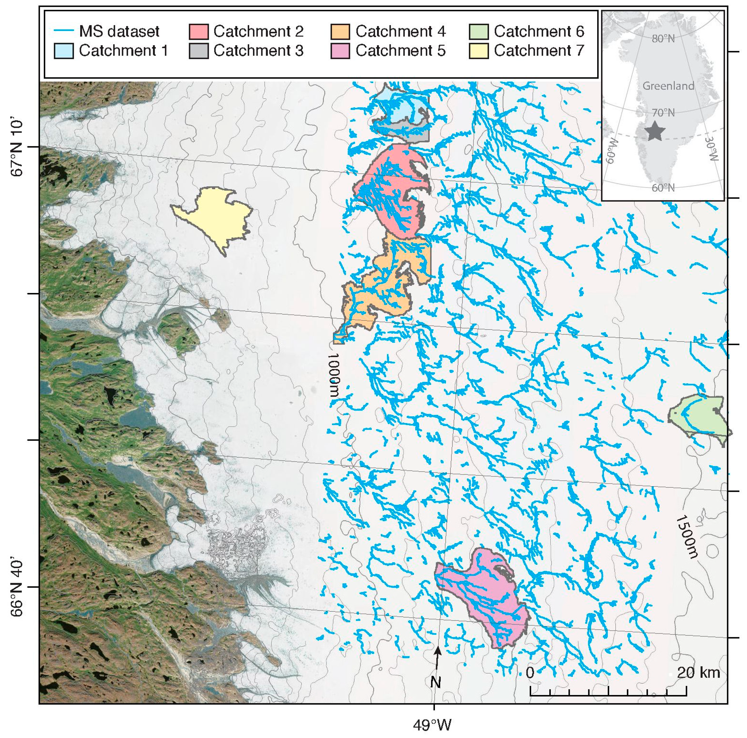
2.1. Datasets and Study Area

The spatial and temporal coverage of the study was constrained by the availability of data. As such, this study is focused on Greenland’s southwestern margin where there is a coincidence of multispectral and topographic datasets. The study area displays extensive supraglacial channel development [2], and has been the focus of previous studies on the GrIS’s surface meltwater systems (e.g., [2,7,10,30]). A total of seven meltwater catchments were delineated through flow routing on the ice surface. Their characteristics are described in Table 2 and their spatial extents are shown in Figure 1. Six of the catchments (Catchments 1–6) were above 1000 m in elevation (‘high’-elevation catchments), where the ice surface has a lower slope and the surface topography is generally uniform [6,47]. Catchment 7 (‘low’-elevation catchment) was delineated on Russell Glacier, where surface slopes are higher and numerous areas of extensional and compressive ice flow create a rough surface, imparting structural elements to the ice surface. To date, there has been no successful, automated methodology developed for delineating supraglacial channels at low elevation, often heavily crevassed parts of the GrIS [6]. This seventh location was chosen specifically to assess the performance of flow routing in delineating channels across a range of ice surface morphologies. Only one low-elevation catchment was selected as MS-derived meltwater channel data were not available for low-elevation locations and the comparison was therefore limited to MD channels.
The dataset used to test the channel extraction by flow routing is a 2 m resolution DEM of large parts of the western GrIS. This ‘Surface Extraction with TIN-based Search-Space Minimization (SETSM)’ DEM is derived from overlapping DigitalGlobe Worldview-1 satellite images and has reported root mean square errors of 3.8 and 2.0 m in the horizontal and vertical, respectively [16]. Experience working with the data suggests that errors in geo-referencing may produce local errors and offsets of several tens of meters between features in the DEM and their real-world coordinates. An offset was similarly observed by Andrews (2015) [37]. Flow routed (FR) channel networks were delineated using flow routing over the SETSM DEM in all seven study catchments, as described in Section 2.2.
The six high-elevation GrIS catchments (Catchments 1–6) extracted from the SETSM DEM using flow routing overlap in space with multispectral-derived meltwater channel networks extracted from 2 m resolution WorldView-2 images dated to July 2012, provided by Smith et al. (2015) [2] (Table 1 and Table 2). This MS dataset represents channels containing meltwater at the time of image acquisition, as identifiable at the 2 m resolution. These overlapping FR and MS datasets are used to compare the channels derived with multispectral and flow routing methodologies. The FR dataset for Catchments 1–3 overlaps in time with the MS datasets, and is dated to one month after the MS dataset for Catchments 4 and 5. The FR dataset for Catchment 6 is from August 2011. Data availability and overlapping spatial extent for the MS and FR datasets limit the spatial extent of our study area and restrict the temporal resolution of our data choices. However, numerous observations suggest that supraglacial meltwater channels (particularly high-order, mainstem channels) perennially re-occupy the same spatial location [1,2,48], even as abandoned channels are advected down-glacier [10]. Furthermore, Lampkin and VanderBerg (2014) [29] observe that the extent of the supraglacial network on the GrIS, observable at 15 m resolution, did not change significantly between early July and early August 2007. Considering melt on the GrIS in 2012 was higher than in 2007, [49], it follows that the fluvially incised channel network was sufficiently unchanged between the July and August image acquisition dates to justify comparison between datasets from the two dates. Again, we distinguish here between water-filled channels, which cannot explicitly be delineated by flow routing (the MS dataset) and whose extent is likely sensitive to timing, and the fluvially incised network, which is unlikely to change following peak melt and will persist until erased by either ablation of the ice surface or burial by seasonal snow.
A third and manually digitized dataset (MD) was also developed from 0.5 m panchromatic images from the WorldView-1 satellite, obtained for a high-elevation GrIS location that overlaps with both a MS- and FR-derived catchment (Catchment 5) and the low-elevation GrIS outlet glacier (Russell Glacier, Catchment 7). The channels in these two images were digitized manually for comparison with FR-delineated channels in both Catchment 5 and Catchment 7, as well as with the MS dataset in Catchment 5. Digitized channels were identified as rectilinear features that are darker and appear recessed relative to the surrounding ice surfaces, and were systematically digitized from the terminal moulin up to the smallest channels that could be readily distinguished in the 0.5 m resolution imagery. They may or may not have been actively filled with water at the time of image acquisition—it is not objectively possible to differentiate water from shadow, particularly in small channels, and therefore we assume that this dataset represents the full extent of the fluvially incised channel network, identifiable at 0.5 m resolution, regardless of the presence of meltwater at the time of image acquisition. Although we developed this dataset to represent an objectively mapped channel network, there are a number of errors inherent in manual digitization, including, for example, user bias, the scale of the image, limitations of panchromatic imagery (particularly with regards to illumination and shading), and difficulty distinguishing flow direction and connectedness, particularly for small channels.
The three datasets represent three distinct types of channel networks. The MS dataset represents active meltwater channels and the MD dataset represents channels that are fluvially incised but may or may not actively contain meltwater at the time of image acquisition. The FR dataset represents the likely path that water takes through a landscape, where network extent is set by a user-specified channel initiation condition. Therefore, these datasets are fundamentally different, and comparing them in this context is not intended to suggest that they are equal attempts to represent the same processes. However, the MD dataset represents fluvial incision at times of maximum melt, and therefore by definition should contain the MS dataset. For this current study, then, these datasets provide independent opportunities to assess flow routing for reproducing channel network structure and characteristics, rather than a direct comparison of their abilities to reproduce the same processes.

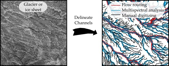
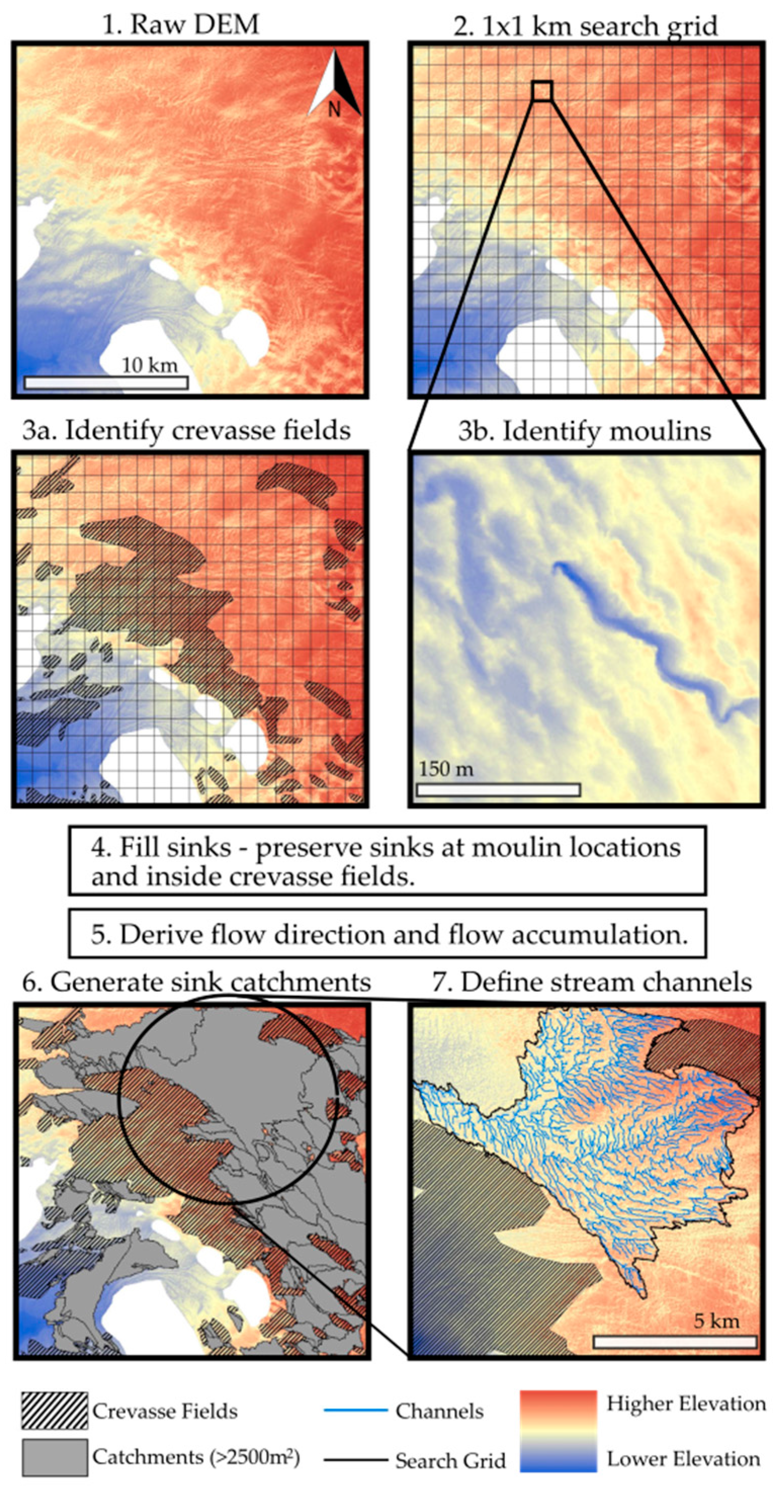
2.2. Channel Network Extraction

The general methodological workflow is illustrated using the DEM from which Catchment 7 was extracted (Figure 2). In the flow routing channel extraction method, flow is routed to moulin locations in the SETSM DEM which are preserved as sinks during the sink filling stage of a flow routing workflow. Two types of potential englacial entry locations are included: sinks in crevasse fields (Figure 2, step 3a) and isolated moulins (Figure 2, step 3b). Although not all crevasses are necessarily englacial entry locations, preserving them as sinks in flow routing conservatively overestimates the presence of sinks in a DEM and limits the catchment extent (Figure 2, step 6). Both crevasse fields and isolated moulins were visually identified and mapped from the DEM and hill shade layers, and sinks within (crevasse fields) or at (moulins) those locations were preserved during sink filling and flow routing. Moulins were readily identifiable as places where channels terminated abruptly, or depressions with no outlets (see Figure 2, step 3b for an example). Crevasse fields were identified as areas with abundant parallel or cross hatched and discontinuous linear depressions. A 1 × 1 km grid was overlain on the DEM, and a grid search pattern was used to assist in the visual identification of sinks (Figure 2, Steps 2, 3a and 3b).
Flow routing was carried out using the ArcHydro toolbox in ArcGIS 10.3.1 [43], which allows for sink preservation during sink filling and flow routing using a standard D8 flow routing algorithm [50]. A multi-directional flow (MDF) routing algorithm was also tested using the MATLAB based TopoToolbox [51]. Similar to findings by Karlstrom and Yang (2016) [10], channel networks delineated with MDF were similar to those delineated with D8. We therefore employ only a D8 flow routing algorithm here as it is coupled with sink preservation tools in ArcHydro (‘Fill Sinks’ tool using IsSink field, followed by ‘Flow Direction with Sinks’ tool). Flow was routed over the ice sheet DEM to visually identified sink locations, generating flow direction, flow accumulation, and sink watershed layers (Figure 2, Steps 4, 5, and 6). Watersheds of interest can then be extracted for further analysis (e.g., Figure 2, Steps 6 and 7, showing the extraction of Catchment 7). Streams were defined by employing a flow accumulation area threshold (e.g., Figure 2, Step 7). Choosing an appropriate channel initiation threshold criteria is a pervasive problem for hydrologists and geomorphologists [52]. It is an unresolved question in alluvial systems, and has not been addressed in supraglacial systems. In this study, we investigate the methodological effects of channel initiation area thresholds on flow routing and meltwater channel delineation as described in the following section.

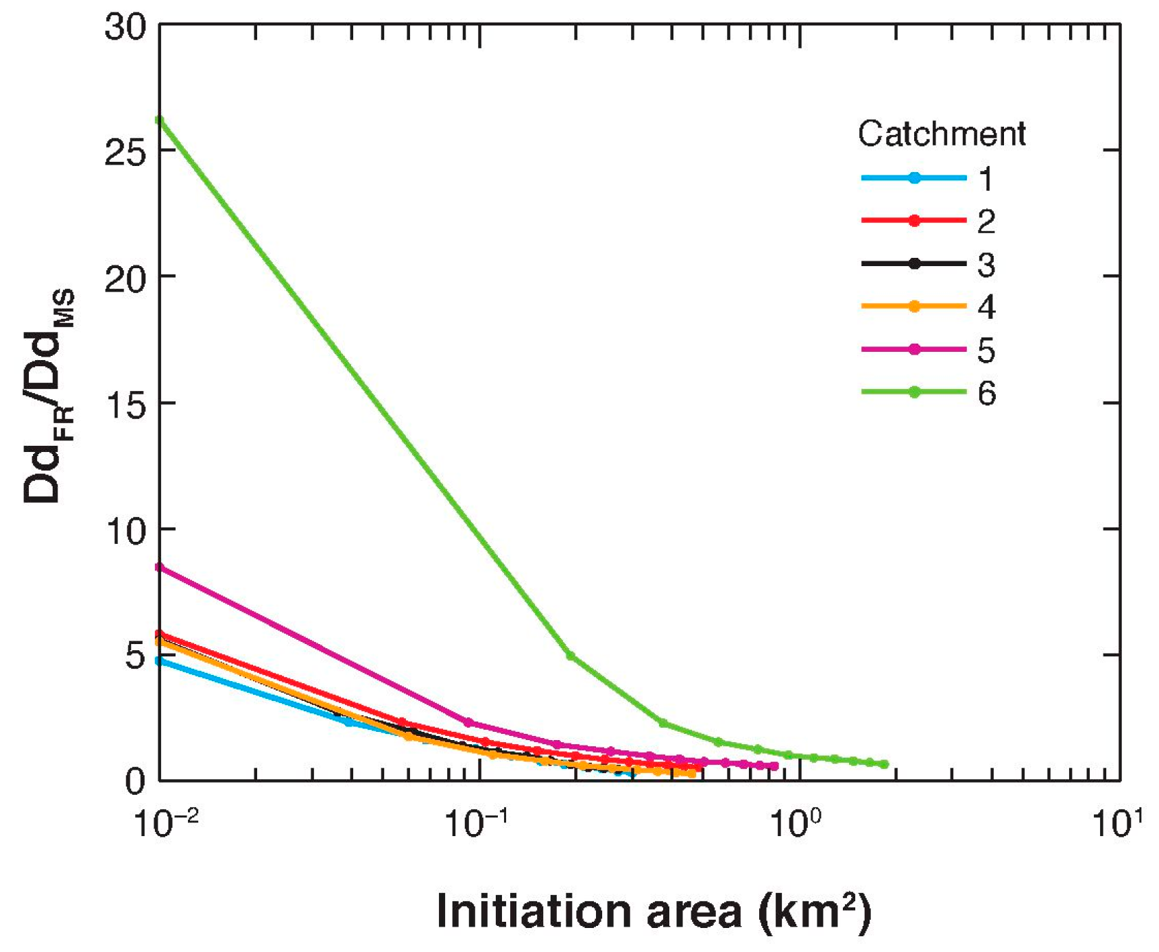
2.3. Channel Initiation Threshold

Field observations suggest several different mechanisms of channel initiation. At the beginning of the melt season, saturated snow may transition into channelized meltwater flow through the formation of rills [1,5,53,54], overflow from slush swamps, lakes or hollows [9,23,55,56], or slush avalanches [57,58]. Although these processes have been empirically described, there has been only one numerical description of the hydrodynamic controls on rill-like supraglacial channel initiation [59]. There is therefore no generalizable and mechanistic methodology for predicting channel initiation points in a flow network. In terrestrial landscapes, inflections in slope/area relationships are often used [60,61,62]; however, it is not yet clear if these relationships can be extended to supraglacial systems [10], and furthermore channel initiation locations are likely below the resolution of available imagery [5,59]. In previous supraglacial research, Karlstrom and Yang (2016) [10] employed a threshold of 0.02 km2 and noted that the resultant channel networks were sensitive to this threshold. Researchers using flow routing will likely need to make locally based judgements on the initiation threshold they employ. In the present study, we avoid testing a specific initiation area and instead specify a range of 10 channel initiation threshold areas, bounded on the lower end by the high density MD networks, and on the upper end by the lower-density MS network.
We assume that the MS-derived initiation points represent an upper bound for the initiation area threshold of the active meltwater network, and the MD-derived initiation points represent a lower bound on the full extent of the fluvially formed network. We calculate initiation point density based on the density of first-order channel endpoints in the MS and MD datasets (number of initiation points divided by catchment area, giving us the average area per initiation point). An MS-derived initiation point density is available for each of the high-elevation catchments, and MD-derived initiation point densities are available for Catchments 5 and 7. The MD-derived point density is applied as the lower bound on channel initiation densities in the other high-elevation catchments, where there are no MD datasets.
Our objective here is not to suggest that the MD dataset channel head densities are directly generalizable to other parts of the GrIS. Indeed, a generalizable methodology for identifying channel initiation points is a complicated issue that is highly dependent on scale and local governing processes [59,62,63], and is beyond the scope of this work. In this work, we investigate the MD threshold as a suitable and conservative channel initiation area recommendation value during or right after peak melt time. In the absence of process based approaches to mapping channel initiation locations, initiation area thresholds may be useful for the purpose of helping researchers map general surface drainage patterns rather than to reveal the physical processes of channel initiation.

2.4. Quantification of Discrepancy between Datasets

Systematic and local offsets sometimes exist between the channel networks from the different datasets due to stitching and georectification errors, and potentially, in the case of datasets with different acquisition dates, due to ice advection. This makes comparisons of the three flow extraction methodologies difficult. A direct spatial comparison would necessitate a large allowable offset, which would complicate the analysis in such a dense network of channels. Because our interest here is an evaluation of flow routing as a means of delineating supraglacial channels, and not an assessment of the datasets, the datasets were spatially adjusted to ensure spatial overlap and facilitate error quantification. This was done by linear translation using readily identifiable channel junctions as displacement links between datasets.
Many flow routing algorithms, including D8, cannot produce realistic channel segments in the absence of topographic variation, including over lakes, and furthermore cannot capture channel bifurcations. As such, channel lengths in lakes and large bifurcations were removed from the datasets. Lakes were visually identified as areas with multiple adjacent, perfectly straight channel segments in the FR dataset, and large braided sections were automatically identified by building polygons from enclosed areas in the MS dataset.
Similarity between the datasets was determined as follows. (1) The lowest drainage density dataset was identified, hereafter referred to as Dataset A (the MS dataset in Catchments 1–6 and the FR dataset in Catchment 7); (2) A 15-m buffer was applied to Dataset A (buffer size determination is explained below); (3) The comparison dataset (Dataset B) was clipped to the buffer; (4) Before comparing the datasets, we removed any lengths of channel equal to or shorter than twice the buffer width in the clipped Dataset B (i.e., any lengths of channels shorter than 30 m). This was done to avoid artificially high match rates due to inclusion of the ends of tributary channels from Dataset B incidentally clipped to the Dataset A buffer.
Similar to Yang et al. (2015) [34], two metrics of comparison were employed: (1) the length of the clipped Dataset B relative to the length of Dataset A, which provides a measure of the similarity between Datasets A and B; and (2) the length of Dataset B outside of the buffer relative to the total length of Dataset B, which provides a measure of how much additional channel network is delineated in Dataset B. Yang et al. (2015) [34] refer to these two metrics of comparison as ‘completeness’ and ‘miscoding’; however, this terminology is not adopted here. As discussed in Section 2.1, the MS dataset represents the lower-density active meltwater channels and the MD and FR datasets target the fluvially incised network; these are therefore not direct comparisons of the same system, and we therefore avoid the implication of a direct comparison implicit in the terms ‘completeness’ and ‘miscoding’.
Appropriate buffer size was determined by comparing match rates between the datasets over a range of buffer sizes. A 15 m buffer size was chosen because additional increases to buffer size produced only moderate gains in match rate and, because the data had been spatially translated, we wanted to employ as small a buffer size as possible while still allowing for some unavoidable minor offset between the datasets.

3. Results

3.1. Comparison between Flow Routing and Multispectral Datasets

3.1.1. Moulin Identification

By design, the FR delineated catchments contain only one sink: large, plainly visible in the DEM, and easily identifiable moulins or crevasses drain the basins at the outlets. In all six FR delineated catchments, the location of these moulins coincides with the location of a moulin identified in the MS imagery. However, in three out of six cases, additional moulins were visually identified in the MS dataset that were not identified from the DEMs. Table 3 shows the breakdown of moulins that were identified in the MS imagery but not in the DEM inspection. The three catchments in which additional moulins were identified are all more than twice as large as the remaining three catchments. In all of these cases, three moulins were missed, cumulatively draining 1.4%, 1.9%, and 8.0% of the three FR catchments, respectively. Thus, only one catchment was overestimated by more than 2% as a product of failing to identify small moulins.

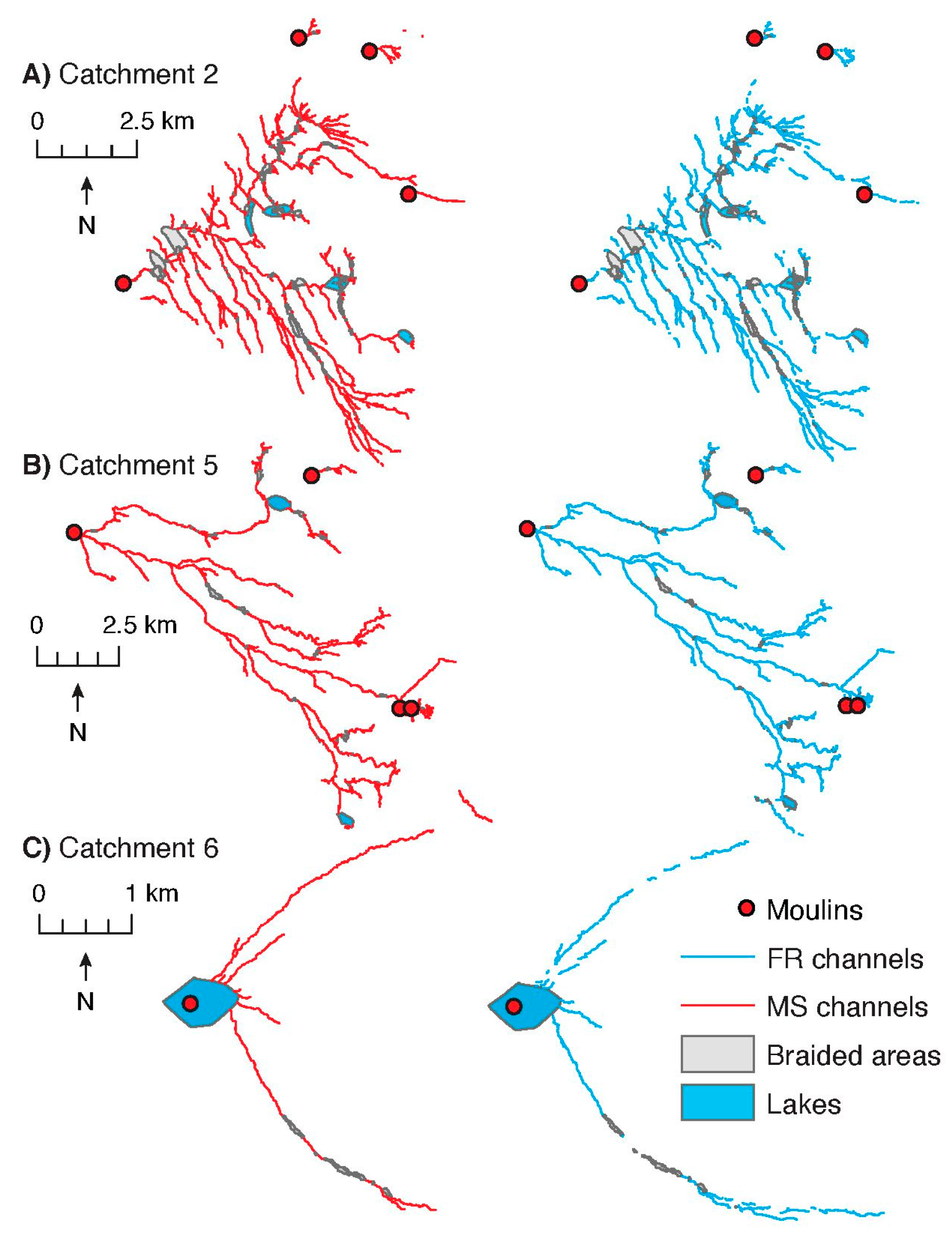
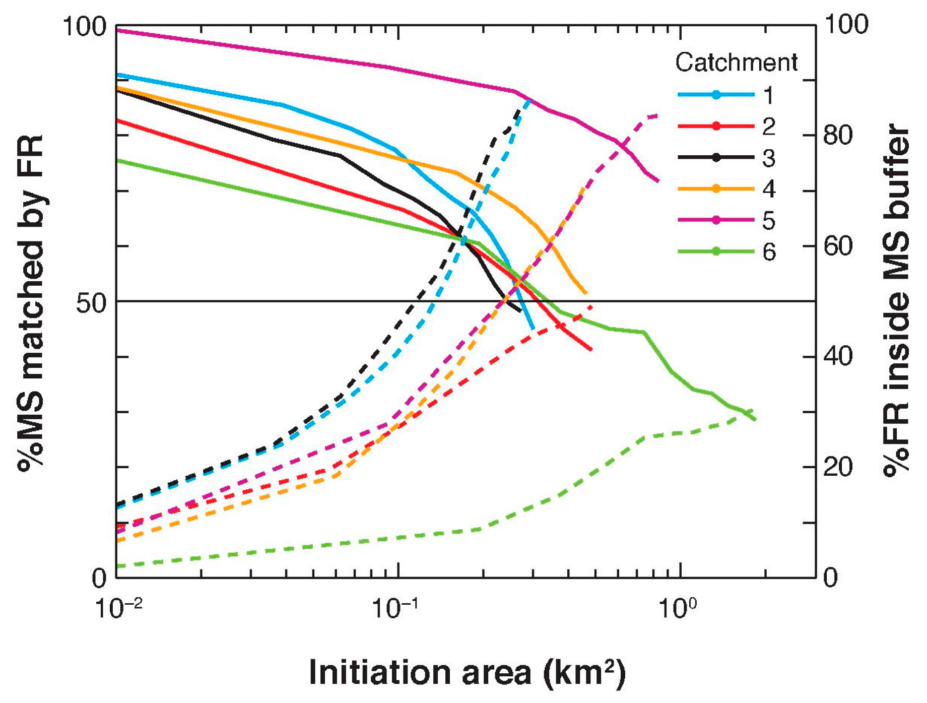
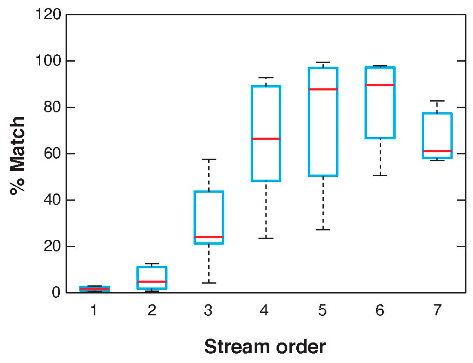
3.1.2. Comparison of Drainage Networks

Drainage density of the MS channels ranges from 1.4 to 2.8 km/km2 for Catchments 1 to 5, and is 0.6 km/km2 in Catchment 6 (Table 3). The channel initiation contributing area thresholds estimated from the MS dataset (first-order channel endpoints over catchment area) vary from 0.3 to 1.8 km2, although only Catchment 6 has an initiation area over 1 km2 (Table 3). All of these initiation area thresholds are more than an order of magnitude higher than estimated from the MD network in Catchment 5, which has an initiation contributing area of 0.01 km2. As a result, the FR channel networks delineated across this range of initiation areas have a wide range of extents and thus a range in the match percentages with the MS dataset and the FR drainage densities. Regardless of the initiation threshold used, flow routing produced higher channel densities than observed with multispectral methods, with this difference increasing with decreasing channel initiation area (Figure 3). This increase was particularly pronounced in Catchment 6, in which drainage density increased by more than an order of magnitude as channel initiation area decreased towards the measured digitized initiation area threshold.
Figure 4 visually compares the MS and the FR datasets in three catchments—Catchment 5 with the greatest percentage overlap between the two datasets, Catchment 6 with the least overlap, and Catchment 2, which is in the middle. The other three catchments are included in the supplementary material. The FR results illustrated here are those produced using the lowest initiation threshold (0.01 km2), close to the digitized initiation threshold and where the match rates are the highest (Figure 3). The depicted FR channels have been clipped to the MS buffer to highlight only those lengths of channel that overlap between the two, excluding the additional lower-order, higher-density channels in the FR dataset outside of the MS buffer. It is clear that, generally, the shape, extent, and placement of the flow routing-derived catchment boundaries are visually consistent with the MS dataset in all test catchments. Even in Catchment 6, with low match rates at higher channel initiation areas, the general morphology of the network is largely similar between the two datasets.
Figure 5 plots the comparisons between the FR and MS datasets. There is a range in the performance of flow routing in the different catchments, and the match percentage depends heavily on the initiation threshold. For example, in Catchment 5, at the (largest) MS-derived channel initiation area, around 72% of the MS dataset is matched by the FR dataset, and almost 85% of the FR dataset is within the MS dataset buffer. In comparison, in Catchment 6, only 31% of the MS dataset is matched by the FR dataset, and only 28% of the FR dataset is within the MS dataset buffer. At the (smallest) MD-derived channel initiation area, 99% of the MS dataset is matched by the FR dataset in Catchment 5, and 75% is matched in Catchment 6. Catchment 6 has the lowest match rates in general. It also has the largest MS channel initiation area (by more than double), the highest mean elevation of the catchments, and a temporal offset of a year between the MS and the FR datasets. Overall, at channel initiation areas similar to those of the MD network in Catchment 5, all the catchments have match rates above 75%, at which point the majority of the FR channel network falls outside of the MS buffer (i.e., the FR networks have significantly higher density than the MS networks).
Although flow routing captures more than 75% (and as much as 99%, in the case of Catchment 5) of the MS channels, these high percentages are only achieved with a small channel initiation threshold, up to two orders of magnitude smaller than the active channel extent measured from the MS dataset. As a result, in all catchments, flow routing at low channel initiation thresholds produces channel networks that are between five and eight times as dense (or more than 30 times as dense in the case of Catchment 6). As can be seen in Figure 6, the MS dataset contains less than 10% of the FR first-order channels (using Strahler stream ordering), and less than 20% of the FR 2nd order channels identified with a 0.01 km2 initiation threshold. If the full extent of these networks were to be plotted in Figure 4, the result would be a much more extensive network with many lower-order channels (Figure 7 shows, for illustrative purposes, the full extent of the FR dataset for Catchment 5 before clipping). It appears that in most cases, MS channels are most similar to FR channels higher than 5th order, based on the ordering of the FR stream network. The drop in match rates for order 7 is likely a result of the fact that there are only three catchments with seventh-order channels. These sections tend to be quite short, therefore mismatched segments become proportionally more pronounced. Manual digitization of Catchment 5 therefore serves to validate whether these high-density, lower-order channels are indeed real. The results of that comparison are summarized in the following section.

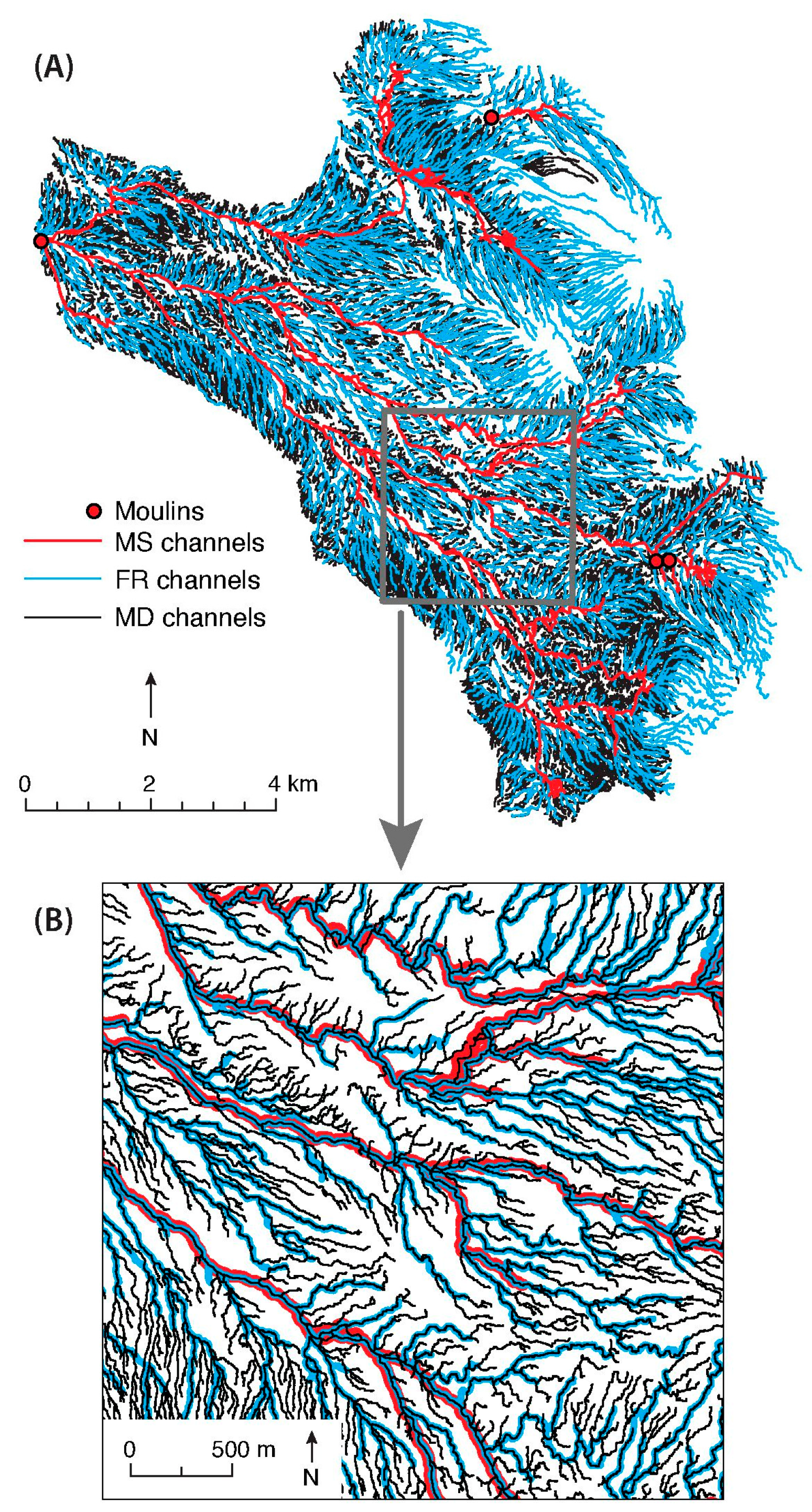
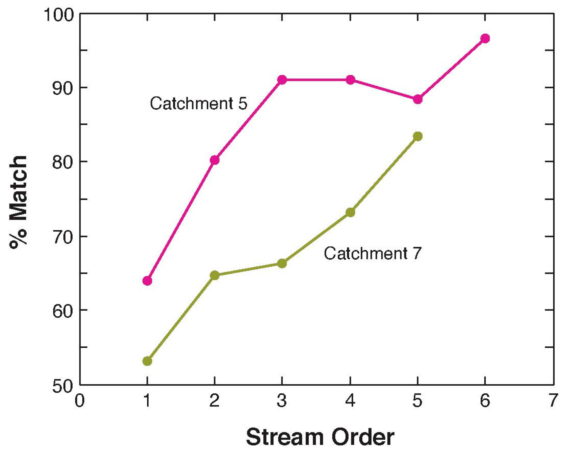
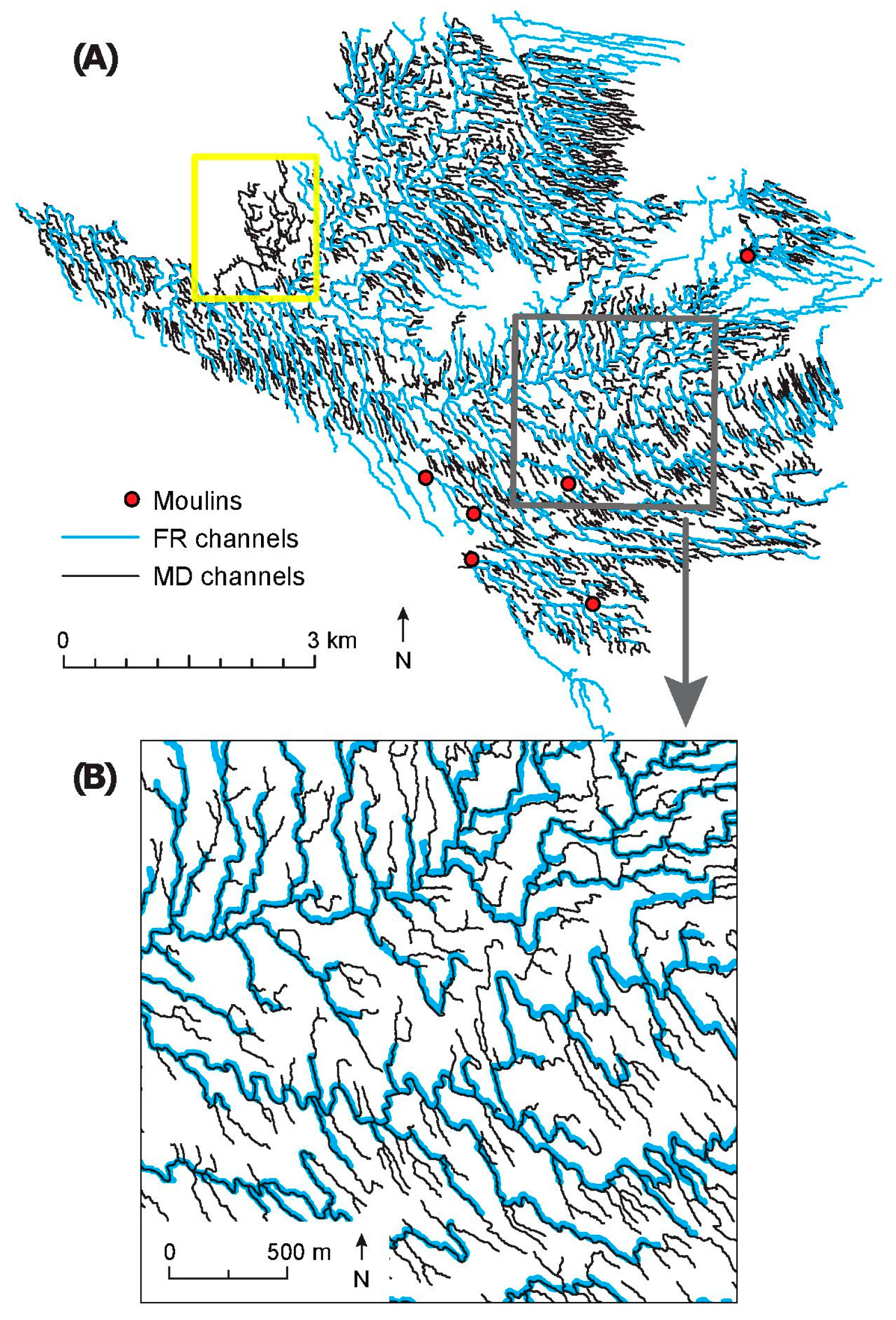
3.2. Comparison with Manually Digitized Datasets

Comparison of the FR dataset with manually digitized datasets serves two aspects of the methods evaluation. Firstly, the higher channel density and larger number of lower-order channels in the FR dataset (relative to the MS dataset) can be compared to the MD dataset which includes low-order and potentially dry channels. Secondly, by utilizing the MD dataset for Catchment 7, the performance of flow routing on varied and rougher ice surfaces can be assessed. In this section we first compare the results of the MD, MS and FR methods in the one overlapping catchment (Catchment 5), and thereafter evaluate the performance of flow routing in Catchment 7.

3.2.1. High-Elevation Catchment

All three datasets (FR, MD, and MS) overlap in Catchment 5. A total channel length of 1590 km was digitized in this catchment, and the manually digitized dataset has very high drainage density (20.2 km/km2), 1.7 times the drainage density identified with flow routing (12.2 km/km2 based on digitized initiation point density of 0.01 km2) and 14 times the density of channels delineated with multispectral methods (1.4 km/km2). Both MS and FR methods reproduced the general network structure (Figure 7), as well as channels at a smaller scale (Figure 7B). The MS dataset matched around 5% more of the MD channel length than did the FR dataset, such that 93% of MS channels overlapped with MD channels as opposed to 88% of the FR channels. A total of 857 km of FR-derived channels overlap with MD channels (54% of the total MD channel length), whereas the MS channels overlapped with 106 km of MD channels (7% of the total MD channel length), consistent with the fact that MS networks reflect the lower-density active meltwater channels.
The performance of flow routing relative to the MD dataset varied by stream order. Stream order is scale-dependent, and we therefore use stream order here as a proxy for relative stream size. Figure 8 demonstrates that for larger, higher-order channels, match rates in Catchment 5 can exceed 95%; however, these match rates drop to close to 70% for first-order channels. Part of this mismatch can be attributed to the fact that, because it is difficult to specify where channels start, low-order channels high up in the network overestimate the upward network extent. This can be seen visually in the upper, westernmost reaches of Figure 7 where long, over predicted low-order FR tributaries can be observed.

3.2.2. Low-Elevation Catchment

The ice surface of low-elevation Catchment 7 is heavily crevassed, yet the main stem channel has a maximum flow length of 21.6 km and width of around 27 m at the moulin entry location, suggesting that there can be significant supraglacial channel development even in the presence of crevasse fields. Digitizing these surface channels was complicated by the surface microtopography—the flow direction in the smaller channels is not always clear to the naked eye, highlighting the advantage of incorporating DEMs into channel network delineation. In total, 532 km of channel length was digitized in Catchment 7. Manual digitizing identified a channel network that was 1.6 times denser than the FR network (12.35 km/km2 as opposed to 7.50 km/km2).
Figure 9 illustrates the MD and FR networks in Catchment 7. The FR network is both underestimated relative to the MD network in one area (illustrated by the yellow square) and overestimated in several others (as can be seen in the upper reaches of the network). Manual delineation included an 11-km branch of channel that was attributed to an adjacent catchment during flow routing, highlighted by the yellow square in Figure 7. The reason for this discrepancy may be a large stitching error in the DEM, and may have resulted in flow being routed to an adjacent catchment. Additionally, six moulins in the upper reaches of the catchment were also identified during manual digitizing that were not identified during the moulin grid search for flow routing sink retention. Five of the moulins were located in a crevassed area on the periphery of the catchment, and drained a total of 8.7% of the flow-routing delineated catchment. The sixth moulin was isolated from the others and drained 3% of the flow-routing delineated catchment.
A total of 75% of the FR channel length matched MD channels. This is more than 10% less than the match rate in the high-elevation catchment. However, as in Catchment 5, match rates are highly dependent on stream size/order. As seen in Figure 8, in the highest-order channels, match rates exceed 90%, and this match drops to below 65% for low-order channels. Again, as in Catchment 5, much of the mismatch in the low-order channels was located at the upper ends of channel reaches, as can be seen at the northernmost and southernmost extents in Figure 9, and in the western part of the reach where a missed moulin resulted in over predicted channel extent. This suggests that mismatch arises not from an inability to delineate channels, but rather from the reliance on simple initiation area thresholds for specifying channel initiation points, as well as moulins that were not identified during the moulin grid search. Close inspection of the more central parts of the network (for example, Figure 9B), show that when channel initiation area is not under predicted, lower-order FR channels visually compare very well with MD channels.

4. Discussion

DEMs are increasingly available at high resolution for ice surfaces [4,16,18,20], and reproducible, accurate methods of extracting surface meltwater channels are necessary for quantifying their temporal and spatial characteristics. Flow routing has numerous advantages for delineating meltwater channels; however, previous research by Yang et al. (2015) [34] on the use of flow routing over moderate-resolution ice surface DEMs found that (1) automated sink preservation thresholds missed over half of mapped moulins and resulted in significantly overestimated drainage network extent; (2) mapped channel networks could be replicated by flow routing with match rates in excess of 85% when a 600 m buffer was applied; (3) less than 40% of the FR drainage network did not match the mapped drainage network, leading to the conclusion that these channels were miscoded. Our results using manual moulin identification and retention on high-resolution DEMs suggest that moulin identification is indeed a persistent problem with flow routing, but that when sink location can be determined, flow routing over a high-resolution DEM can produce channel networks that largely resemble both MS and MD channel networks, using a buffer size of only 15 m. Furthermore, our results support the suggestion of Yang and Smith (2016) [6] that high-resolution DEMs may provide a viable solution to delineating supraglacial channels from low-elevation GrIS catchments.

4.1. Moulins

Visual identification of moulins is labor-intensive, and thus in some ways offsets the practical advantages of using flow routing over other channel delineation methodologies. However, there are no automatic moulin detection methodologies currently available, and manual identification was used by Smith et al. (2015) [2] in the production of the extensive MS dataset employed here as well as by Karlstrom and Yang (2016) [10] and Andrews (2016) [37]. We tested moulin identification with DEM and hill shade layers, as optical imagery associated with the SETSM dataset was not available to us. Digitization from topographic raster layers may be necessary in other studies when optical imagery is not available or accessible (e.g., LiDAR-derived DEMs), or is not sufficiently well georeferenced to the topographic data to easily couple identified moulins with the DEM (e.g., [64]).

4.2. Flow Routing in High-Elevation Catchments

In almost all of the high-elevation catchments, flow routing did an exceptional job of delineating the shape, extent and placement of channels identified through multispectral methods. Match rates of up to 99% could be achieved between the FR network and the MS network. Several important limitations of the comparison are worth noting: firstly, lakes and large braided areas were removed as they cannot be properly captured by D8 flow routing. Integration of more sophisticated flow routing algorithms (e.g., [65]) with sink preservation algorithms (e.g., [45]) may better handle flow dispersion and channel bifurcation. However, neither we nor Karlstrom and Yang (2016) [10] observed significant differences in flow networks derived with multiple flow direction or Dinf algorithms, respectively. Secondly, channel density and the match rates are highly dependent on the initiation area used to define the channels. Match rates were ubiquitously lower at large channel initiation thresholds based on the low drainage density MS datasets, and higher at the smaller channel initiation thresholds generalized from the MD dataset. However, at lower channel initiation areas, most of the FR channel network lay outside of the MS dataset buffer because low channel initiation thresholds result in significantly higher channel densities. Therefore, although it was possible to achieve high match rates, it was necessary to densify the network, implying that the active meltwater extent is not solely or explicitly a function of contributing area, and a more adaptive criterion for channel initiation may be required. Initial modeling work by Mantelli et al. (2015) [59] suggested that slope, meltwater depth, and small scale roughness exert primary controls on channel spacing and initiation. Thus, accurate modeling of channel networks requires a more flexible initiation criterion than channel initiation contributing area, and integrates the evolution of the supraglacial network over time.
Our high-elevation catchment MD channel density of 20.1 km/km2 falls within the range of 6.0–31.7 km/km2 digitized in a catchment of similar elevation by Smith et al. (2015) [2], who found that digitized channel networks were at least seven times as dense as those derived from multispectral imagery. Comparison of the FR network with these MD channel networks suggests that almost 90% of the FR channels overlap with MD channels and may thus be fluvially formed, that the full extent of the fluvial channel network is at a minimum five times denser than the multispectral network, and that MS channels generally represent higher-order channels in the full fluvially incised networks. Therefore, for researchers interested in representing channel networks, including lower-order channels, it appears that in the absence of a more process-based and generalizable criterion for channel initiation, small channel initiation areas can be prescribed without risk of overestimating the fluvially formed channel network. However, the match rates between the FR and MD dataset decrease with decreasing stream order. Although match rates for first-order channels were still above 70%, this is significantly less confidence than can be had in higher-order channels.
The MS and FR networks in Catchment 6 had the lowest match rates across the range of channel initiation thresholds tested. This may have been because there was a difference of a year between the acquisition date of the DEM and MS imagery. However, the main channels in the MS imagery matched FR channels at low channel initiation thresholds, suggesting that the time difference was at least not solely responsible for the mismatch. Catchment 6 differs from the other catchments in its higher elevation (an average of 1528 m versus a range of average elevation from 1147 to 1244 m in the other high-elevation test catchments) and lower slope (8.2% compared to a range of 10.7%–16.1% for the other catchments). It also has a much lower MS channel density than the other catchments. Very little data exist pertaining to the spatial variability of supraglacial channels or their controls; however, Yang et al. (2016) [8] noted a decrease in channel density with increasing elevation, supporting the notion that at higher elevations less meltwater is available to incise channel networks. Fluvial channel incision is dependent on channel slope and water discharge (e.g., [61]); it is therefore possible that fluvial channels and networks in higher-elevation catchments, characterized by lower slopes and lower meltwater supply, are less developed than in lower elevation catchments. As such, multispectral rather than flow routing methods may be better suited to identifying meltwater channels in low-slope, high-elevation catchments.
Conversely, the mismatch may arise from the presence of perennial snow and firn cover at this high-elevation catchment. The mean equilibrium altitude in this part of the GrIS is estimated as 1553 m a.s.l [66]. Observations suggest that extensive firn saturation and active surface runoff were present on snow covered ice above this average equilibrium line altitude in 2012 [67]. Catchment 6 is located at a mean elevation of 1528 m, suggesting that supraglacial channel development was occurring in saturated firn and that subsurface meltwater flow may have been occurring in this catchment. This subsurface flow would not have been detectable by MS techniques, and may contribute to some of the high mismatch in this catchment.

4.3. Flow Routing in Low-Elevation Catchments

Although the ‘low-elevation’ catchment in this study (Catchment 7) is still above 800 m, its characteristics differ significantly from the ‘high-elevation’ catchments. It is steeper, and widespread neighboring zones of extensional and compressive flow create a rough surface with significant microtopography (as can be seen in Figure 2). Manual digitizing nonetheless reveals a well-developed and extensive supraglacial channel network. Previously, there has been limited automated delineation of supraglacial channels over heavily crevassed ice surfaces (e.g., [2,10]), in spite of the fact that the coincidence of crevasses and supraglacial meltwater channels have been linked to high ice flow velocity and variability [3,13,68]. Yang and Smith (2016) [6] noted that multispectral methods often fail to fully map supraglacial river networks at low elevations (below 1200 m) on the GrIS, although their methods were limited by the 15-m resolution of Landsat data. There is excellent SETSM coverage of many low-elevation sectors of the GrIS and its outlet glaciers. This research therefore represents an attempt to identify a readily useable method for extracting surface meltwater channel characteristics from this morphologically complex ice surface utilizing this new and expanding dataset. Flow routing is able to replicate the major structure and extent of a manually mapped low elevation catchment. Match rates above 80% and 90% for fourth- and fifth-order channels, respectively, and above 75% for second- and third-order channels, but drop to below 65% for first-order channels. The mismatches in the low-order channels arise primarily in the higher reaches of the catchment where small moulins are difficult to identify from the DEM and variable channel initiation points cannot be adequately captured with a threshold initiation area. Although no overlapping MS dataset was available for Catchment 7, it is reasonable to expect that multispectral methods would be of limited utility in such a rough, shadowed surface, and that flow routing provides a reasonable and physically objective method for delineating channels [6]. Moulin identification will likely be an ongoing challenge in rough ice, in particular, and the dangers of overestimating channel extent may be more significant here [13].
Interestingly, the digitized channel density and digitized initiation point density are lower by 1.6 and 2.2 times, respectively, when compared to the MD network in Catchment 5. If both slope and melt rate control channel initiation [59], higher channel density would be expected in this lower elevation, higher slope catchment. Whereas Yang et al. (2016) [8] observed a decrease in channel density with increasing elevation, we do not observe this between our low- and high-elevation catchments. It is compelling that MD initiation point density in particular is lower in Catchment 7 than it is in the higher-elevation, digitized Catchment 5. This suggests that density is not low simply because there is more water draining through the ice in this crevassed region, but rather because the points of initiation are more widely spaced. This unexpected observation suggests that there are other controls on channel initiation and density that need to be explored, or that the mechanisms of channel initiation differ between this rough surface ice and the generally crevasse-free ice surface of the high-elevation catchments.

4.4. Limitations and Considerations

There are a several important limitations of this work that must be considered when interpreting the results. Firstly, there are a number of manual steps incorporated into this workflow that offset, to some degree, the ease and rapidity of flow routing. These steps include manual identification of crevasses, moulins, lakes, and channel initiation densities. Previous work suggests approaches to automating parts of this process, including predicting moulin location (e.g., [69,70]), automated crevasse detection (e.g., [46]), and automated lake mapping (e.g., [30]). The objective of the work presented here is not to develop a fully automated approach to delineating the supraglacial fluvial network, but rather to employ flow routing under ideal conditions of known sink location to address previous reservations about flow routing over ice surfaces [34]. The success of flow routing demonstrated here will support researchers in incorporating flow routing into their research with whatever modifications necessary.
Secondly, as stated throughout, flow routing cannot directly map meltwater channel extent. Although we compare it here to the MS dataset, we do so only to take advantage of a complementary dataset that serves as a point of relative comparison. Given the ambiguity in channel initiation area threshold, we suggest that researchers most interested in meltwater extent at a given point in time are best served by multispectral methods. Although flow routing does not directly allow researchers to infer channel network extent, derived channels may be useful to researchers interested in channel morphometrics that are dependent on fluvial processes acting over timescales of channel evolution. This has been done in supraglacial channels for catchment characteristics and slope-area analysis [10], and extensively in terrestrial systems for network structure and self-similarity (see [71]), and scale independent morphometrics such as sinuosity and junction angles. General network geometry, independent of initiation area, may also be of interest to researchers for a range of methodological purposes such as satellite image geo-registration [72].

5. Conclusions

In this paper, we employ a newly available high-resolution (2 m) surface DEM of the Greenland Ice Sheet [16] to test flow routing as a method for delineating supraglacial channels. We manually identify moulins and crevasse fields as sink locations and retain the sinks during flow routing. We compared the resultant channel networks to both manually digitized channels as well as a dataset of supraglacial channels delineated by Smith et al. (2015) [2] from 2 m resolution multispectral imagery. We find that flow routing is capable of replicating up to 99% of the multispectrally derived channel networks when employed with a 0.01 km2 channel initiation threshold, and can produce networks with significantly higher channel density. We confirm, using manually digitized channel networks, that when moulin locations are properly determined, this higher channel density is real rather than an artifact of the flow routing methodology. The accuracy of flow routing decreases with decreasing stream order, likely as a result of uncertainties regarding channel initiation area. Furthermore, we find that flow routing over high-resolution DEMs provides a viable methodology to extract supraglacial channel networks at low elevations on the GrIS, where high slopes and microtopography otherwise make channel extraction challenging. Channel initiation threshold requires further investigation, but researchers wishing to employ flow routing to delineate supraglacial channels may safely employ quite low initiation thresholds (0.01 km2, in this particular study) during or after peak melt without risk of overestimating channel extent. Researchers will nonetheless need to pick channel initiation thresholds that reflect local surface conditions. Low-elevation catchments may have higher initiation thresholds because of the importance of microtopography in determining channel heads, whereas high-elevation catchments may have higher initiation thresholds because of low melt rates.

Supplementary Materials

The following are available online at www.mdpi.com/2072-4292/8/12/988/s1, Figure S1: MS and FR datasets for Catchments 1, 3 and 4.

Acknowledgments

The authors acknowledge the funding provided by the National Science and Engineering Research Council of Canada through a graduate student award to Leonora King, and an NSERC Discovery Grant (number: 249673-12) to Marwan A. Hassan. WorldView-1 imagery was granted by the DigitalGlobe Foundation, and the SETSM dataset is provided through the Polar Geospatial Centre. We would like to thank Laurence Smith for providing the MS dataset, Yarra Hassan and Rawan Hassan for digitizing the MD channels, Eric Leinberger for producing the figures, and Mark Jellinek for his input throughout the process. We thank five anonymous reviewers for critical feedback that greatly improved the paper.

Author Contributions

Leonora King conceived and designed the study, processed and analyzed the data, and drafted the manuscript. Marwan A. Hassan and Gwenn Flowers provided supervisory support and discussion of the research idea and methodology. Marwan A. Hassan, Gwenn Flowers, and Kang Yang provided input and feedback on the analysis and editorial input on the manuscript.

Conflicts of Interest

The authors declare no conflict of interest.

References

  1. Knighton, A. Channel form and flow characteristics of supraglacial streams, Austre Okstindbreen, Norway. Arct. Alp. Res. 1981, 13, 295–306. [Google Scholar] [CrossRef]
  2. Smith, L.C.; Chu, V.W.; Yang, K.; Gleason, C.J.; Pitcher, L.H.; Rennermalm, A.K.; Legleiter, C.J.; Behar, A.E.; Overstreet, B.T.; Moustafa, S.E.; et al. Efficient meltwater drainage through supraglacial streams and rivers on the southwest Greenland ice sheet. Proc. Natl. Acad. Sci. USA 2015, 112, 1001–1006. [Google Scholar] [CrossRef] [PubMed]
  3. Wyatt, F.R.; Sharp, M.J. Linking surface hydrology to flow regimes and patterns of velocity variability on Devon Ice Cap, Nunavut. J. Glaciol. 2015, 61, 387–399. [Google Scholar] [CrossRef]
  4. Rippin, D.M.; Pomfret, A.; King, N. High resolution mapping of supra-glacial drainage pathways reveals link between micro-channel drainage density, surface roughness and surface reflectance. Earth Surf. Process. Landf. 2015, 40, 1279–1290. [Google Scholar] [CrossRef]
  5. Karlstrom, L.; Gajjar, P.; Manga, M. Meander formation in supraglacial streams. J. Geophys. Res. Earth Surf. 2013, 118, 1897–1907. [Google Scholar] [CrossRef]
  6. Yang, K.; Smith, L.C. Internally drained catchments dominate supraglacial hydrology of the southwest Greenland Ice Sheet. J. Geophys. Res. Earth Surf. 2016, 121, 1891–1910. [Google Scholar] [CrossRef]
  7. Gleason, C.J.; Smith, L.C.; Chu, V.W.; Legleiter, C.J.; Pitcher, L.H.; Overstreet, B.T.; Rennermalm, A.K.; Forster, R.R.; Yang, K. Characterizing supraglacial meltwater channel hydraulics on the Greenland Ice Sheet from in situ observations. Earth Surf. Process. Landf. 2016, 41, 2111–2122. [Google Scholar] [CrossRef]
  8. Yang, K.; Smith, L.C.; Chu, V.W.; Pitcher, L.H.; Gleason, C.J.; Rennermalm, A.K.; Li, M. Fluvial morphometry of supraglacial river networks on the southwest Greenland Ice Sheet. GISci. Remote Sens. 2016, 53, 459–482. [Google Scholar] [CrossRef]
  9. Dozier, J. Part II: Channel adjustments in supraglacial stream. In Studies of Morphology and Stream Action on Ablating Ice; Arctic Institute of North America: Montreal, QC, Canada, 1970; pp. 69–117. [Google Scholar]
  10. Karlstrom, L.; Yang, K. Fluvial supraglacial landscape evolution on the Greenland Ice Sheet. Geophys. Res. Lett. 2016, 43, 2683–2692. [Google Scholar] [CrossRef]
  11. Sundal, A.V.; Shepherd, A.; Nienow, P.; Hanna, E.; Palmer, S.; Huybrechts, P. Melt-induced speed-up of Greenland ice sheet offset by efficient subglacial drainage. Nature 2011, 469, 521–524. [Google Scholar] [CrossRef] [PubMed]
  12. Banwell, A.F.; Willis, I.C.; Arnold, N.S. Modeling subglacial water routing at Paakitsoq, W Greenland. J. Geophys. Res. Earth Surf. 2013, 118, 1282–1295. [Google Scholar] [CrossRef]
  13. Joughin, I.; Das, S.B.; Flowers, G.E.; Behn, M.D.; Alley, R.B.; King, M.A.; Smith, B.E.; Bamber, J.L.; Van Den Broeke, M.R.; Van Angelen, J.H. Influence of ice-sheet geometry and supraglacial lakes on seasonal ice-flow variability. Cryosphere 2013, 7, 1185–1192. [Google Scholar] [CrossRef]
  14. Schoof, C. Ice-sheet acceleration driven by melt supply variability. Nature 2010, 468, 803–806. [Google Scholar] [CrossRef] [PubMed]
  15. Van de Wal, R.; Boot, W.; van den Broeke, M.; Smeets, C.; Reijmer, C.; Donker, J.; Oerlemans, J. Large and rapid melt-induced velocity changes in the ablation zone of the Greenland ice sheet. Science. 2008, 321, 111–114. [Google Scholar] [CrossRef] [PubMed]
  16. Noh, M.-J.; Howat, I.M. Automated stereo-photogrammetric DEM generation at high latitudes: Surface Extraction with TIN-based Search-space Minimization (SETSM) validation and demonstration over glaciated regions. GISci. Remote Sens. 2015, 52, 198–217. [Google Scholar] [CrossRef]
  17. Yang, K.; Smith, L.C. Supraglacial streams on the greenland ice sheet delineated from combined spectral–shape information in high-resolution satellite imagery. IEEE Geosci. Remote Sens. Lett. 2013, 10, 801–805. [Google Scholar] [CrossRef]
  18. DGGS Staff. Elevation Datasets of Alaska: Alaska Division of Geological and Geophysical Surveys Digital Data Series 4 2013. Available online: http://maps.dggs.alaska.gov/elevationdata/ (accessed on 30 November 2016).
  19. High Resolution Lidar Digital Elevation Models and Low Resolution Shaded Relief Maps of Antarctica from USGS. Available online: http://nsidc.org/data/ANTARCTIC_DEM (accessed on 30 November 2016).
  20. Shean, D.E.; Alexandrov, O.; Moratto, Z.M.; Smith, B.E.; Joughin, I.R.; Porter, C.; Morin, P. An automated, open-source pipeline for mass production of digital elevation models (DEMs) from very-high-resolution commercial stereo satellite imagery. ISPRS J. Photogramm. Remote Sens. 2016, 116, 101–117. [Google Scholar] [CrossRef]
  21. Fountain, A.; Walder, J. Water flow through temperate glaciers. Rev. Geophys. 1998, 36, 299–328. [Google Scholar] [CrossRef]
  22. Irvine-Fynn, T.D.L.; Hodson, A.J.; Moorman, B.J.; Vatne, G.; Hubbard, A.L. Polythermal glacier hydrology: A review. Rev. Geophys. 2011, 49, 1–37. [Google Scholar] [CrossRef]
  23. Ferguson, R. Sinuosity of supraglacial streams. Geol. Soc. Am. Bull. 1973, 251–255. [Google Scholar] [CrossRef]
  24. Parker, G. Meadering of supraglacial melt streams. Water Resour. Res. 1975, 11, 551–552. [Google Scholar] [CrossRef]
  25. Dozier, J. An examination of the variance minimization tendencies of a supraglacial stream. J. Hydrol. 1976, 31, 359–380. [Google Scholar] [CrossRef]
  26. Marston, R.A. Supraglacial Stream Dynamics on the Juneau Icefield. Ann. Assoc. Am. Geogr. 2015, 73, 597–608. [Google Scholar] [CrossRef]
  27. Iken, A. The effect of the subglacial water pressure on the sliding velocity of a glacier in an idealized numerical model. J. Glaciol. 1981, 27, 407–421. [Google Scholar]
  28. Thomsen, H.H. Photogrammetric and satellite mapping of the margin of the inland ice, West Greenland. Ann. Glaciol. 1986, 8, 164–167. [Google Scholar]
  29. Lampkin, D.J.; VanderBerg, J. Supraglacial melt channel networks in the Jakobshavn Isbrae region during the 2007 melt season. Hydrol. Process. 2014, 28, 6038–6053. [Google Scholar] [CrossRef]
  30. Fitzpatrick, A.A.W.; Hubbard, A.L.; Box, J.E.; Quincey, D.J.; Van As, D.; Mikkelsen, A.P.B.; Doyle, S.H.; Dow, C.F.; Hasholt, B.; Jones, G.A. A decade (2002–2012) of supraglacial lake volume estimates across Russell Glacier, West Greenland. Cryosphere 2014, 8, 107–121. [Google Scholar] [CrossRef] [Green Version]
  31. McGrath, D.; Colgan, W.; Steffen, K.; Lauffenburger, P.; Balog, J. Assessing the summer water budget of a moulin basin in the sermeq avannarleq ablation region, Greenland ice sheet. J. Glaciol. 2011, 57, 954–964. [Google Scholar] [CrossRef]
  32. Das, S.; Joughin, I.; Behn, M.; Howat, I.; King, M.; Lizarralde, D.; Bhatia, M. Fracture propagation to the base of the Greenland ice sheet during supraglacial lake drainage. Science 2008, 320, 778–782. [Google Scholar] [CrossRef] [PubMed]
  33. Poinar, K.; Joughin, I.; Das, S.B.; Behn, M.D.; Lenaerts, J.T.M.; Van Den Broeke, M.R. Limits to future expansion of surface-melt-enhanced ice flow into the interior of western Greenland. Geophys. Res. Lett. 2015, 42, 1800–1807. [Google Scholar] [CrossRef]
  34. Yang, K.; Smith, L.C.; Chu, V.W.; Gleason, C.J.; Li, M. A Caution on the Use of Surface Digital Elevation Models to Simulate Supraglacial Hydrology of the Greenland Ice Sheet. IEEE J. Sel. Top. Appl. Earth Obs. Remote Sens. 2015, 8, 5212–5224. [Google Scholar] [CrossRef]
  35. Banwell, A.F.; Arnold, N.S.; Willis, I.C.; Tedesco, M.; Ahlstrøm, A.P. Modeling supraglacial water routing and lake filling on the Greenland Ice Sheet. J. Geophys. Res. 2012, 117, 1–11. [Google Scholar] [CrossRef]
  36. Arnold, N.S.; Banwell, A.F.; Willis, I.C. High-resolution modelling of the seasonal evolution of surface water storage on the Greenland Ice Sheet. Cryosphere 2014, 8, 1149–1160. [Google Scholar] [CrossRef]
  37. Andrews, L.C. Spatial and Temporal Evolution of the Glacial Hydrologic System of the Western Greenland Ice Sheet: Observational and Remote Sensing Results. Ph.D. Thesis, University of Texas at Austin, Austin, TX, USA, 2015. [Google Scholar]
  38. Tarboton, D.G.; Bras, R.L.; Rodriguiez-Iturbe, I. On the extraction of channel networks from digital elevation data. Hydrol. Process. 1991, 5, 81–100. [Google Scholar] [CrossRef]
  39. Arnold, N. A new approach for dealing with depressions in digital elevation models when calculating flow accumulation values. Prog. Phys. Geogr. 2010, 34, 781–809. [Google Scholar] [CrossRef]
  40. Gulley, J.D.; Benn, D.I.; Screaton, E.; Martin, J. Mechanisms of englacial conduit formation and their implications for subglacial recharge. Quat. Sci. Rev. 2009, 28, 1984–1999. [Google Scholar] [CrossRef]
  41. Nienow, P.; Hubbard, B. Surface and Englacial Drainage of Glaciers and Ice Sheets. Encycl. Hydrol. Sci. 2005. [Google Scholar] [CrossRef]
  42. Conrad, O.; Bechtel, B.; Bock, M.; Dietrich, H.; Fischer, E.; Gerlitz, L.; Wehberg, J.; Wichmann, V.; Bohner, J. System for Automated Geoscientific Analyses (SAGA). Geosci. Model Dev. 2015, 8, 1991–2007. [Google Scholar] [CrossRef]
  43. ESRI ArcGIS Desktop: Release 10.3.1 2016; Environmental Systems Research Institute: Redlands, CA, USA, 2016.
  44. GRASS Development Team Geographic Resources Analysis Support System (GRASS) Software 2015. Available online: https://grass.osgeo.org/ (accessed on 30 November 2016).
  45. Maidment, D. Arc Hydro: GIS for Water Resources; ESRI Inc.: Redlands, CA, USA, 2002. [Google Scholar]
  46. Jóhannesson, T.; Björnsson, H.; Pálsson, F.; Sigurðsson, O.; Þorsteinsson, Þ. LiDAR mapping of the Snæfellsjökull ice cap, western Iceland. Jökull 2003, 61, 19–32. [Google Scholar]
  47. Clason, C.C.; Mair, D.W.F.; Nienow, P.W.; Bartholomew, I.D.; Sole, A.; Palmer, S.; Schwanghart, W. Modelling the transfer of supraglacial meltwater to the bed of Leverett Glacier, Southwest Greenland. Cryosphere 2015, 9, 123–138. [Google Scholar] [CrossRef]
  48. Ewing, K. Part II: Supraglacial streams on the Kaskawulsh glacier, Yukon Territory. In Studies of Morphology and Stream Action on Ablating Ice; Arctic Institute of North America: Montreal, QC, Canada, 1970; pp. 131–167. [Google Scholar]
  49. Nghiem, S.V.; Hall, D.K.; Mote, T.L.; Tedesco, M.; Albert, M.R.; Keegan, K.; Shuman, C.A.; DiGirolamo, N.E.; Neumann, G. The extreme melt across the Greenland ice sheet in 2012. Geophys. Res. Lett. 2012, 39, 6–11. [Google Scholar] [CrossRef]
  50. O’Callaghan, J.F.; Mark, D.M. The extraction of drainage networks from digital elevation data. Comput. Vis. Graph. Image Process. 1984, 28, 323–344. [Google Scholar] [CrossRef]
  51. Schwanghart, W.; Kuhn, N. TopoToolbox: A set of Matlab functions for topographic analysis. Environ. Model. Softw. 2010, 25, 770–781. [Google Scholar] [CrossRef]
  52. Montgomery, D.; Foufoula-Georgiou, E. Channel network source representation using digital elevation models. Water Resour. Res. 1993, 29, 3925–3934. [Google Scholar] [CrossRef]
  53. Kamintzis, J. The Spatial Dynamics of An Annual Supraglacial Meltwater Channel in the Ablation Zone of Haut Glacier d’Arolla, Switzerland; Aberyswyth University: Aberystwyth, UK, 2015. [Google Scholar]
  54. Stenborg, T. Glacier drainage connected with ice structures. Geogr. Ann. Ser. A Phys. Geogr. 1968, 50, 25–53. [Google Scholar] [CrossRef]
  55. Brykała, D. Evolution of supraglacial drainage on Waldemar Glacier (Spitsbergen) in the period 1936–1998. In Proceedings of the Polish Polar Studies: 25th International Polar Symposium, Warsaw, Poland, 16–17 September 1998; pp. 247–261.
  56. Hodgkins, R. Glacier hydrology in Svalbard, Norwegian High Arctic. Quat. Sci. Rev. 1997, 16, 957–973. [Google Scholar] [CrossRef]
  57. Fountain, A.G. Effect of Snow and Firn Hydrology on the Physical and Chemical Characteristics of Glacial Runoff. Hydrol. Process. 1996, 10, 509–521. [Google Scholar] [CrossRef]
  58. Onesti, L.J. Slushflow release mechanism: A first approximation. In Avalanche Formation, Movement and Effect; IAHS: Wallingford, UK, 1987; pp. 331–336. [Google Scholar]
  59. Mantelli, E.; Camporeale, C.; Ridolfi, L. Supraglacial channel inception: Modeling and processes. Water Resour. Res. 2015, 51, 7044–7063. [Google Scholar] [CrossRef]
  60. Montgomery, D.; Dietrich, W. Landscape dissection and drainage area-slope thresholds. In Process Models and Theoretical Geomorphology; Kirkby, M., Ed.; John Wiley & Sons Ltd.: Hoboken, NJ, USA, 1994; p. 417. [Google Scholar]
  61. Tucker, G.; Bras, R. Hillslope processes, drainage density, and landscape morphology. Water Resour. Res. 1998, 34, 2751–2764. [Google Scholar] [CrossRef]
  62. Montgomery, D.R.; Dietrich, W.E. Where do channels begin? Nature 1988, 336, 232–234. [Google Scholar] [CrossRef]
  63. Zhang, W.; Montgomery, D. Digital elevation model grid size, landscape representation, and hydrologic simulations. Water Resour. Res. 1994, 30, 1019–1028. [Google Scholar] [CrossRef]
  64. Doctor, D.H.; Young, J.A. An evaluation of Automated Gis Tools for Delineating Karst Sinkholes and Closed Depressions From 1-Meter Lidar-Derived Digital Elevation Data. In Proceedings of the 13th Multidisciplinary Conference on Sinkholes and the Engineering and Environmental Impacts of Karst, Carlsbad, NM, USA, 6–10 May 2013; pp. 449–458.
  65. Tarboton, D. A new method for the determination of flow directions and upslope areas in grid digital elevation models. Water Resour. Res. 1997, 33, 309–319. [Google Scholar] [CrossRef]
  66. Van de Wal, R.S.W.; Boot, W.; Smeets, C.J.P.P.; Snellen, H.; van den Broeke, M.R.; Oerlemans, J. Twenty-one years of mass balance observations along the K-transect, West Greenland. Earth Syst. Sci. Data 2012, 4, 31–35. [Google Scholar] [CrossRef]
  67. Mikkelsen, A.B.; Hubbard, A.; Macferrin, M.; Eric Box, J.; Doyle, S.H.; Fitzpatrick, A.; Hasholt, B.; Bailey, H.L.; Lindbäck, K.; Pettersson, R. Extraordinary runoff from the Greenland ice sheet in 2012 amplified by hypsometry and depleted firn retention. Cryosphere 2016, 10, 1147–1159. [Google Scholar] [CrossRef] [Green Version]
  68. Palmer, S.; Shepherd, A.; Nienow, P.; Joughin, I. Seasonal speedup of the Greenland Ice Sheet linked to routing of surface water. Earth Planet. Sci. Lett. 2011, 302, 423–428. [Google Scholar] [CrossRef]
  69. Colgan, W.; Steffen, K. Modelling the spatial distribution of moulins near Jakobshavn, Greenland. In Proceedings of the IOP Conference Series: Earth and Environmental Science, Copenhagen, Denmark, 10–12 March 2009.
  70. Clason, C.; Mair, D.W.F.; Burgess, D.O.; Nienow, P.W. Modelling the delivery of supraglacial meltwater to the ice/bed interface: Application to southwest Devon Ice Cap, Nunavut, Canada. J. Glaciol. 2012, 58, 361–374. [Google Scholar] [CrossRef]
  71. Rodriguiez-Iturbe, I.; Rinaldo, A. Fractal River Basins: Chance and Self-Organization; Cambridge University Press: Cambridge, UK, 1997. [Google Scholar]
  72. Yang, K.; Karlstrom, L.; Smith, L.C.; Li, M. Automated High-Resolution Satellite Image Registration Using Supraglacial Rivers on the Greenland Ice Sheet. IEEE J. Sel. Top. Appl. Earth Obs. Remote Sens. 2016. [Google Scholar] [CrossRef]
Figure 1. Extent of multispectral (MS) dataset, with the six overlapping flow routing-derived catchments identified as polygons. Base map from ESRI ArcMap World Imagery (2016) [43]. Star in inset map marks approximate location.
Remotesensing 08 00988 g001
Figure 2. Workflow for channel delineation, exemplified by the extraction of Catchment 7 from a DEM tile (SETSM tile 15_38_5_5). The processing steps are described in Section 2.2. Only catchments above 2500 m2 are shown in Step 6; however, many more catchments are present after flow direction processing.
Remotesensing 08 00988 g002
Figure 3. The ratio of flow-routed (FR) to multispectral (MS) drainage density as a function of initiation contributing area. Initiation area is bounded on the lower end by the manually digitized (MD) initiation area for Catchment 5 and on the upper end by the measured initiation area for each MS catchment.
Remotesensing 08 00988 g003
Figure 4. A visual comparison of flow-routed (FR) and multispectral (MS) channel networks in three of the test catchments (Catchments 2 (A); 5 (B); and 6 (C)).
Remotesensing 08 00988 g004
Figure 5. The performance of flow routing (FR) relative to multispectral (MS) methods across a range of initiation thresholds, bounded on the low end by the digitized initiation threshold from Catchment 5 and on the upper end by the initiation point density derived from the MS dataset for each catchment. Solid lines represent the percent of the FR dataset within the MS buffer (left y-axis), and the dashed lines represent the percentage of the FR network length inside the MS buffer (right y-axis).
Remotesensing 08 00988 g005
Figure 6. The match rates between multispectral (MS) and flow-routed (FR) datasets in the six high-elevation catchments by FR Strahler stream order, using a 0.01 km2 initiation threshold.
Remotesensing 08 00988 g006
Figure 7. A comparison of the manually digitized (MD) network, the flow-routed (FR) network with a channel initiation condition based on the MD network, and the multispectral (MS) dataset for Catchment 5. In (A), the datasets are overlain in the order of the legend entries shown, with the lowest density network (MS) on top, and the highest density (MD) on the bottom. This figure illustrates the relative morphologies and extents of the networks. In (B), the gray square from (A) is enlarged and the order in which the networks are overlain is reversed. The widths of the networks are differentiated for illustrative purposes—MS is the thickest, and MD is the thinnest. This figure illustrates the overlap between the networks.
Remotesensing 08 00988 g007
Figure 8. The match percentages between manually digitized (MD) and flow-routed (FR) channels in Catchment 5 and 7, by FR-derived Strahler stream order.
Remotesensing 08 00988 g008
Figure 9. Comparison of flow-routed (FR) and manually digitized (MD) channel networks in Catchment 7, the low-elevation catchment. As in Figure 6, in (A) the FR channels are overlaid on MD channels to illustrate the channel networks morphologies. In (B) the order is reversed, with FR on the bottom, illustrated with a thicker line, to highlight the overlap between the networks.
Remotesensing 08 00988 g009
Table 1. Summary of datasets used.
Channel Extraction MethodImagery SourceAcquisition Date(s)Resolution (m)Reference
Flow Routing (FR)SETSM DEM (derived from WorldView-1)24 July 2012 (Catchments 1–3)2.0[16]
20 August 2012 (Catchments 4 and 5)
20 August 2011 (Catchment 6)
Multispectral (MS)WorldView-218–23 July 20122.0[2]
Manual Digitizing (MD)WorldView-121 July 2012 (Catchment 7)0.5n/a
20 August 2012 (Catchment 5)
Table 2. Summary of study catchments.
CatchmentCentral CoordinatesArea (km2)Mean Slope (%)Mean Elevation (m)Datasets
FRMSMD
149°12′48.853″W23.111.01172XX
67°15′3.539″N
249°13′58.816″W71.511.91147XX
67°8′52.932″N
349°11′56.907″W15.510.71230XX
67°13′15.191″N
449°14′5.529″W78.211.61119XX
67°2′24.692″N
548°52′8.931″W79.213.01244XXX
66°41′56.575″N
648°18′22.375″W31.28.21528XX
66°55′17.935″N
749°44′22.47″W42.216.1838X X
67°6′19.874″N
Table 3. Summary of moulins identified from optical imagery in the multispectral imagery that were not visually identified from the DEM and hill shade layers, and drainage densities and initiation thresholds derived from the MS dataset.
CatchmentMissed MoulinsMS Drainage Density (km/km2)MS Initiation Threshold (km2)
NumberArea Drained
100.0%2.80.3
238.0%2.20.5
300.0%2.40.3
431.4%2.00.5
531.9%1.40.8
600.0%0.61.8

