Design Issues for Hexapod Walking Robots


Department DICEM, University of Cassino and Southern Lazio, Via di Biasio 43, Cassino 03043 (Fr), Italy
*
Author to whom correspondence should be addressed.
Robotics 2014, 3(2), 181-206; https://doi.org/10.3390/robotics3020181
Submission received: 31 March 2014
/
Revised: 7 May 2014
/
Accepted: 15 May 2014
/
Published: 10 June 2014
(This article belongs to the Special Issue Advances in Biomimetic Robotics)
Abstract
:Hexapod walking robots have attracted considerable attention for several decades. Many studies have been carried out in research centers, universities and industries. However, only in the recent past have efficient walking machines been conceived, designed and built with performances that can be suitable for practical applications. This paper gives an overview of the state of the art on hexapod walking robots by referring both to the early design solutions and the most recent achievements. Careful attention is given to the main design issues and constraints that influence the technical feasibility and operation performance. A design procedure is outlined in order to systematically design a hexapod walking robot. In particular, the proposed design procedure takes into account the main features, such as mechanical structure and leg configuration, actuating and driving systems, payload, motion conditions, and walking gait. A case study is described in order to show the effectiveness and feasibility of the proposed design procedure.
1. Introduction
Legged hexapod robots are programmable robots with six legs attached to the robot body. The legs are controlled with a degree of autonomy so that the robot can move within its environments, to perform intended tasks. Hexapod robots can be suitable for terrestrial and space applications, and they can include features such as omnidirectional motion, variable geometry, good stability, access to diverse terrain, and fault tolerant locomotion [1].
One of the motivating factors often given for pursuing the development of hexapod robots is that they can climb over obstacles larger than the equivalent sized wheeled or trucked vehicle. In fact, the use of wheels or crawlers limits the size of the obstacle that can be climbed to half the diameter of the wheels. On the contrary, legged robots can overcome obstacles that are comparable with the size of the machine leg [2]. Hexapod walking robots also benefit from a lower impact on the terrain and have greater mobility in natural surroundings. This is especially important in dangerous environments like mine fields, or where it is essential to keep the terrain largely undisturbed for scientific reasons [3]. Hexapod legged robots have been used in exploration of remote locations and hostile environments such as seabed [4,5], in space or on planets [6,7] in nuclear power stations [8], and in search and rescue operations [9]. Beyond this type of application, hexapod walking vehicles can also be used in a wide variety of tasks such as forests harvesting, in aid to humans in the transport of cargo, as service robots and entertainment.
Despite the above referenced aspects, many challenges remain before hexapod walking robots can have a more widespread use. Some of their current disadvantages include higher complexity and cost, low energy efficiency [10], and relatively low speed. Walking robots are in fact complex and expensive machines, consisting of many actuators, sensors, transmissions and supporting hardware.
This paper gives a wide overview of the state of the art on six-leg walking robots aiming to identify the main design issues and constraints that influence the technical feasibility and performance of these systems. Then, a design procedure is proposed in order to systematically design a six-leg walking robot. In particular, the proposed design procedure takes into account mechanical structure and leg configuration, actuating and drive mechanisms, payload, motion conditions, walking gait and control system. A case study is described, referring to previous experiences at LARM in Cassino in order to show the effectiveness and feasibility of the proposed design procedure.
2. State of Art Overview
2.1. Early Designs
The first hexapods can be identified as robots based on a rigidly predetermined motion so that an adaptation to the ground was not possible. Early researches in the 1950s were focused on assigning the motion control completely by a human operator manually [11].
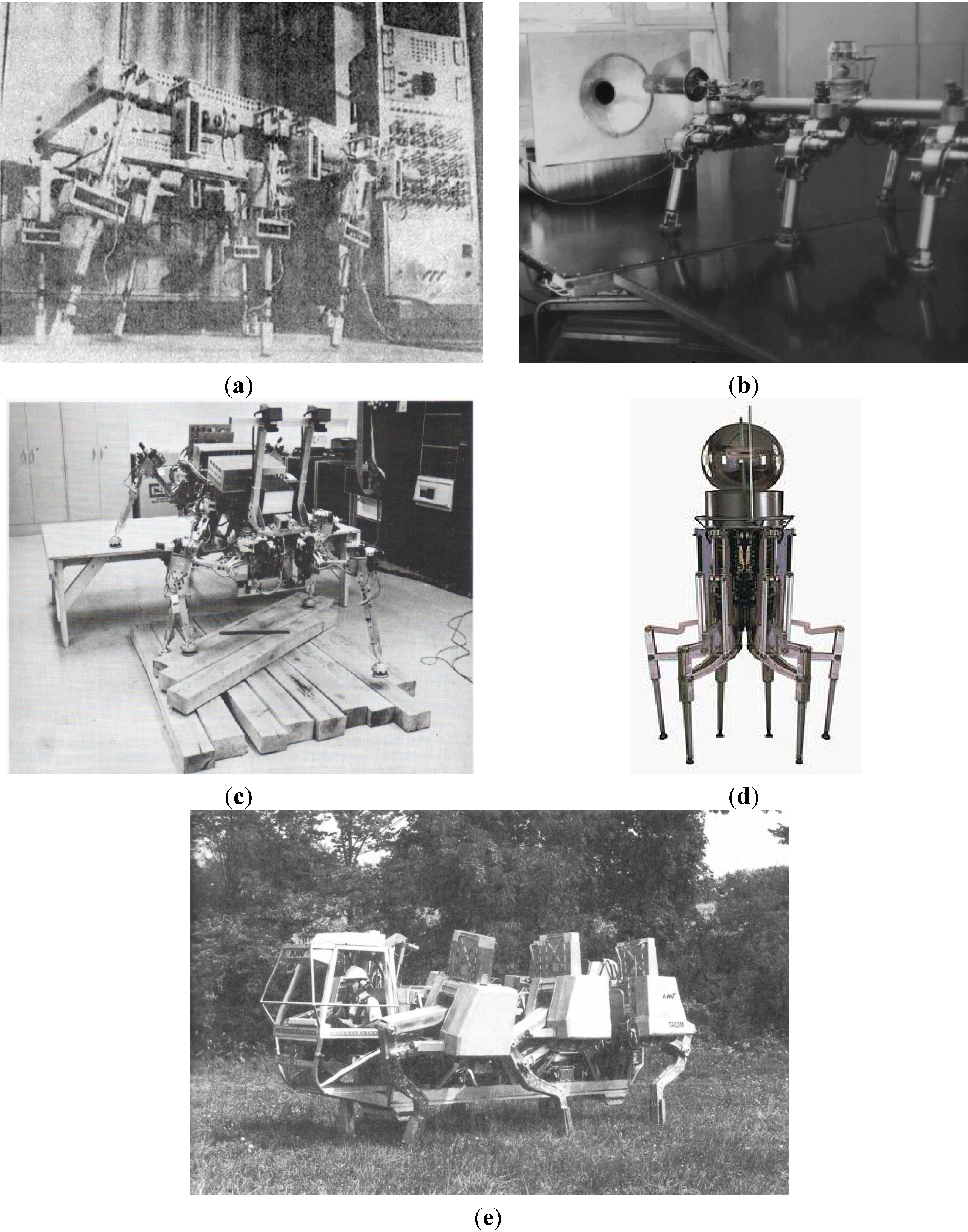
One of the first successful hexapod robot was constructed at University of Rome in 1972 (Figure 1a) as a computer-controlled walking machine with electric drives [12]. In the middle 70s, at the Russian Academy of Sciences in Moscow, a six-legged walking machine was developed with a mathematical model of motion control. It was equipped with a laser scanning range finder and was connected with a two-computer control system [13]. In 1976, Masha hexapod walking robot was designed at Moscow State University (Figure 1b). The robot had a tubular axial chassis, articulated legs with three DoFs [14]. The hexapod was able to negotiate obstacles using contact on the feet and a proximity sensor. Ohio State University in 1977 developed a six-legged insect-like robot system called “OSU Hexapod” [15]. This hexapod was kept tethered and was made to walk short distances over obstacles (Figure 1c). In 1983, Carnegie-Mellon University developed a “Six-Legged Hydraulic Walker” [16], a first man-carrying hexapod capable of navigating rough terrain using different types of gaits. The hexapod used a combination of hydraulic feedback, computer control and human control and was about 2.5 m long and the same width. It weighted about 800 kg and was powered by a 13 kW gasoline engine.
Figure 1.
Early hexapod design: (a) University of Rome’s hexapod; (b) MASHA hexapod; (c) OSU hexapod; (d) ODEX I hexapod; (e) ASV hexapod.
Figure 1.
Early hexapod design: (a) University of Rome’s hexapod; (b) MASHA hexapod; (c) OSU hexapod; (d) ODEX I hexapod; (e) ASV hexapod.

In 1984, Odetic Inc., California, USA, developed Odex I [17], a six-legged radially symmetric hexapod robot which used an onboard computer to play back pre-programmed motions (Figure 1d). Its onboard computer could be operated remotely and the robot moved under its own power. Using remote human control or the prerecorded motions, the hexapod could climb obstacles such as stairs or a pickup truck. Odex I weighed 136 kg; each leg was able to lift 180 kg. In 1985, the “NMIIIA” Hexapod Manned Rover was developed in Russia [18]. This hexapod was designed for investigating the walking propulsive device and control system. NMIIA had a mass of 750 kg; its load-carrying capacity was 80 kg; travel speed was 0.7 km/h. In 1989, the Ohio State University started the Adaptive Suspension Vehicle project [19]. The six-legged robot, shown in Figure 1e, used hydraulic actuation being powered by an internal combustion engine. A human was able to operate it through a joystick while the individual control of each leg was assured by a central computer. As main characteristics, its 250 kg payload capacity, and the possibility to surpass 1.8 m width ditches and climb vertical steps of maximum 1.65 m should be mentioned. A hexapod walking robot named Aquarobots was constructed in 1989 and used for underwater measurements of ground profiles for the construction of harbors [20]. A small hexapod robot named Genghis with 0.35 m length and 1 kg weight was developed in the same year [21]. The behavior of Genghis was not explicitly controlled, but was built by adding layers of control on top of existing simpler layer. This approach was different to the more traditional method of task decomposition.
Attila and Hannibal hexapod robots were built in the Mobot Lab in the early 1990s [22]; they were very sophisticated autonomous robots for their size, possessing over 19 degrees of freedom, more than 60 sensory inputs, eight microprocessors and real-time behavior. TUM Walking Machine was developed in 1991. The robot was designed and steered similar to a stick insect [23]; the control system was realized as a neural structure. AMBLER (Autonomous MoBiLe Exploration Robot) was a hexapod robot developed by the Jet Propulsion Laboratory during the mid-90s for operating under the particular constraints of planetary terrain [24]. The robot was about 5 m tall, up to 7 m wide, and weighed 2500 kg. While most robots bend their legs to step and walk, Ambler’s legs remain vertical, while they swing horizontally, adopting a telescope like displacement to touch the ground.
2.2. Recent Developments
The two last decades have been characterized by a rapid development of control systems technology. Hexapod robots were equipped with various sensing systems. Artificial Intelligence systems were widely applied to the analysis of environment and motion of robots on a complex surface.
A series of bio inspired robots was developed at Case Western Reserve University (USA) at the end the 90s, such as, for example, Robot III that had a total of 24 DoFs. Robot III architecture was based on the structure of cockroach, trying to imitate their behavior [25]. In particular, each rear leg had three DoFs, each middle leg four DoFs and each front leg five DoFs. Similarly, Biobot was a biomimetic robot physically modeled as the American cockroach (Periplaneta Americana) and powered by pressurized air [26]. This hexapod had a great speed and agility. Each leg of the robot had three segments, corresponding to the three main segments of insect legs: coxa, femur, and tibia.
Hamlet was a hexapod robot constructed at the University of Canterbury, New Zealand [27]. Its legs were all identical and each had three revolute joints. Hamlet’s application task was to study force and position control on uneven terrain.
In 2001, a project named RHex commenced [28]; RHex design comes from a multidisciplinary and multi-university DARPA funded effort that applies mathematical techniques from dynamical systems theory to problems of animal locomotion. Hexapod design consists of a rigid body with six compliant legs, each with one DoF (Figure 2a). Thus, RHex has only six motors that rotate the legs such as a wheel.
Figure 2.
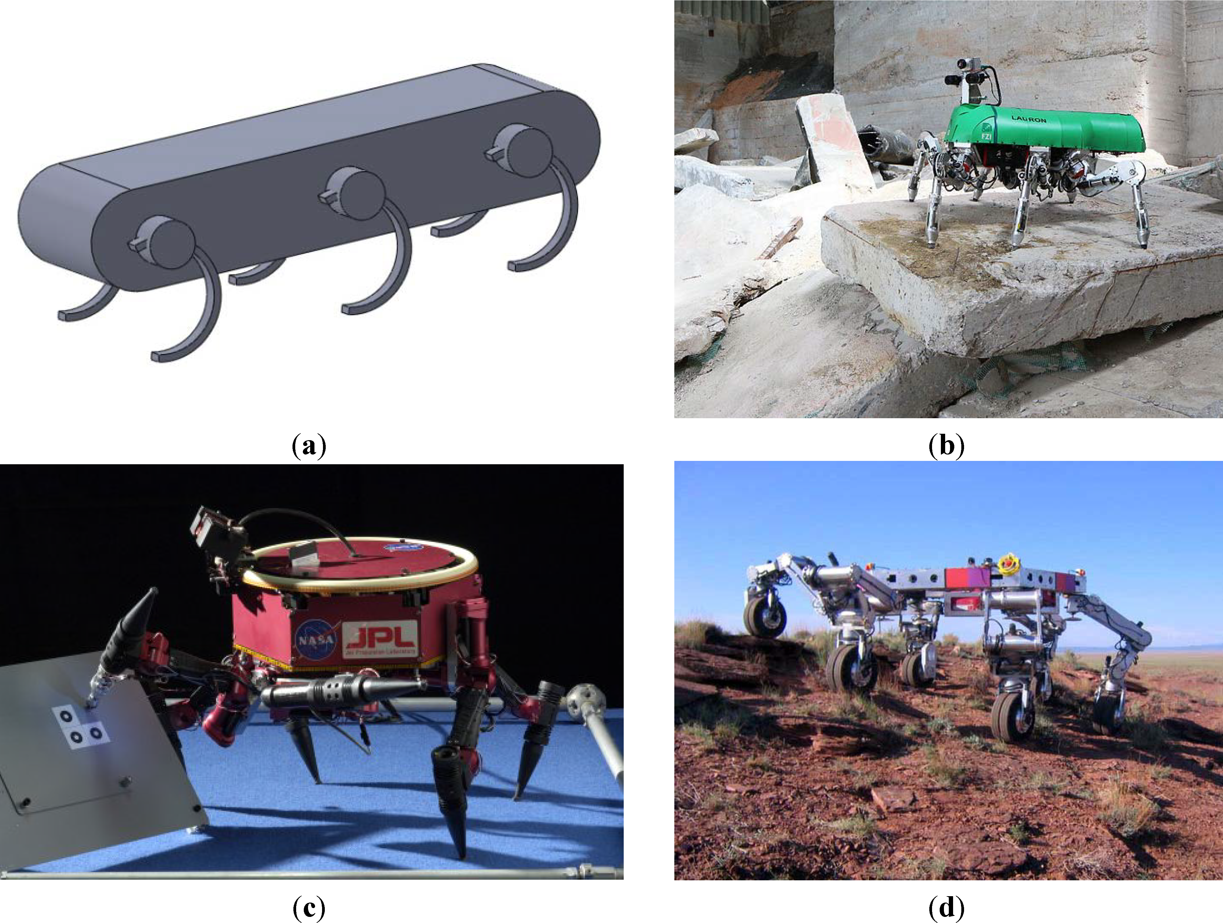
Recent developments in hexapod design: (a) RHex basic architecture; (b) Six-legged walking robot LAURON V from the FZI Research Center for Information Technology in Karlsruhe, Germany; (c) One configuration of the LEMUR prototype: the front limbs function as legs and arms, with integrated tools; (d) ATHLETE during experimental tests.
Figure 2.
Recent developments in hexapod design: (a) RHex basic architecture; (b) Six-legged walking robot LAURON V from the FZI Research Center for Information Technology in Karlsruhe, Germany; (c) One configuration of the LEMUR prototype: the front limbs function as legs and arms, with integrated tools; (d) ATHLETE during experimental tests.

Several prototypes of Rhex have been developed. At present the project is still active.
Lauron V hexapod robot (Figure 2b) was the result of about 10 years of progressive improvement on the previous configurations Lauron I, II, III and IV. LAURON [29] is biologically-inspired by the stick insect. Like this insect, the robot has six legs fixed to a central body. Each of the six legs is actuated by four joints. Each foot has a three-axis force sensor, and each motor has a current sensor that detects forces opposing to its movement. At present the project is still active.
Gregor I reproduces the cockroach’s agility where the locomotion control is based on the theory of the Central Pattern Generator [30]. Gregor I had a biological inspiration where each leg pair has a unique design. The front leg pair and the middle leg pair have three DoFs on each leg, and the rear leg pair has two DoFs. Another hexapod robot called Sprawlita [31] was developed following the basic principles of locomotion of cockroaches: self-stabilizing posture, different functions for the legs, passive visco-elastic structure, open-loop control and integrated construction. In 2005, the hexapod robot named BILL-Ant-p was developed [32]. The robot was based on ants’ behavior and it is composed of three DoFs on each leg with six force-sensing feet, a three-DoF neck and head, and actuated mandibles with force-sensing for a total of 28 DoFs.
A series of hexapod named LEMUR (Limbed Excursion Mechanical Utility Robots robot) was developed by Jet Propulsion Laboratory [33] with the goals of using robots for repair and maintenance in near-zero gravity on the surface of spacecraft (Figure 2c). MARS (Multi Appendage Robotic System) was a hexapod mobile robotic research platform developed after the LEMUR project for similar applications by employing radial symmetry. MARS platforms were capable of walking in any direction without turning [34].
In 2004, a six-legged lunar robot called ATHLETE was developed by the Jet Propulsion Laboratory [35]. This robot had the ability to roll rapidly on rotating wheels over flat smooth terrain and walk carefully on fixed wheels over irregular and steep terrain. ATHLETE had a payload capacity of 450 kg, a diameter of around 4 m and a reach of around 6 m (Figure 2d).
AQUA was an amphibious hexapod robot developed with six independently-controlled leg actuators [36]. One of the most important features of this robot was the ability to switch from walking to swimming gaits as it is moving from a sand beach or surf-zone to deep water. The underwater walking robot CR200 was built as based on the concept of Crabster [37]. The application field was inspection of shipwrecks or scour and survey of seafloor in high current and turbid environments. The hexapod robot called RiSE is able to climb on a variety of vertical surfaces as well as demonstrating horizontal mobility [38]. A mechanism applied in RiSE uses compliant micro spines on its feet to reliably attach to textured vertical surfaces, in order to carry the payload while the robot climbs. COMET hexapods are a serious of robots designed to operate on extremely unstructured terrain [39]. The latest prototype, COMET IV, is a hydraulically driven hexapod involving walking with the force/impedance control, fully autonomous navigation with laser mapping and teleoperation. Mantis is a hexapod robot hydraulic powered developed by Micromagic Systems. It stands nearly 3 m tall and weighs about 2 tons; at present, it is one of the biggest hexapod robots in the world [40].
Many hexapod rovers for space exploration have been designed and built in the last years. A very rich reference of this vehicle and their design issues can be found in [41].
Given the wide variety of existing hexapod robots, several of the above described prototypes have been detailed in a specific table (Table 1). It provides a quick comparison tool for referring to the main features.

| Main Characteristics | Main Performance | |||||||||
|---|---|---|---|---|---|---|---|---|---|---|
| Robot Name | Mass (Kg) | Length (cm) | Width (cm) | Height (cm) | Total DoFs | Max Speed (m/s) | Gait/Mobility | Power (W) | Year | Application Tasks |
| Ambler | 2700 | 500 | 500 | 700 | 12 | 0.007 | Wave Free | 1900 | 1989 | Planetary exploration |
| ASV | 3200 | 520 | 240 | 300 | 15 | 1.0 | Wave Free | 26000 | 1989 | Navigate on uneven terrains |
| Hannibal | 2.7 | 35 | NA | 20 | 19 | 0.04 | Wave Free | NA | 1989 | Planetary exploration |
| Tum | 23 | 80 | 40 | 100 | 18 | 0.3 | Wave | 500 | 1991 | Hexapod following biological principles |
| Biobot | 11 | 58 | 14 | 23 | 18 | NA | NA | NA | 2000 | Locomotion over rough terrain |
| Hamlet | 13 | 40 | 28 | 40 | 18 | 0.1 | Wave Free | 52 | 2001 | Testing force and position control |
| Rhex | 7 | 53 | 20 | 15 | 6 | 0.55 | Wave Free | 100 | 2001 | Hexapod with reduced actuators |
| Sprawlita | 0.27 | 16 | NA | NA | 12 | 0.35 | Wave | NA | 2002 | Robots inspired to cockroaches |
| Lauron III | 18 | 50 | 30 | 80 | 18 | 0.4 | Wave Free | NA | 1999–2003 | Testing a hierarchical walk controller |
| Genghis | 1 | 40 | 15 | NA | 12 | 0.04 0.12 | Wave Free | NA | 2004 | Developing of a reactive controller |
| Aqua II | 16.5 | 64 | 44 | 13 | 6 | 0.7 1 | Land Water | 200 | 2010 | Underwater hexapod robot |
| Bill-Ant-p | 2.3 | 47 | 33 | 16 | 22 | 0.004 | Wave | 25 | 2005 | Biologically inspired legged robot |
| Gregor I | 1.2 | 30 | 9 | 4 | 16 | 0.03 | NA | 25 | 2006 | Robot inspired on cockroaches. |
| Athelete | 850 | 2.75 | 2.75 | 2 | 36 | 2.78 0.016 | Wheleed Wave | NA | 2006 | Navigate on rough soil of on the Moon |
| RiSe | 2.8 | 41 | NA | NA | 12 | NA | Wave | NA | 2006 | Hexapod climbing robots |
| Comet IV | 2120 | 280 | 330 | 250 | 24 | 0.278 | Wave | 20600 | 2009–2011 | Hexapod for multitasks on outdoor environment |
| CR200 | 600 | 250 | 200 | 130 | 18 | 0.5 | Wave | 20000 | 2013 | Walk either on land or underwater in the turbulent surf zone |
| Mantis | 1900 | 420 | 220 | 280 | 18 | NA | Wave | 42000 | 2013 | Entertainment |
NA means data not available.
2.3. Hexapod Robots’ Performance Indices
The following indices have been proposed in the literature in order to compare legged robots which have different masses, shape and sizes:
- Duty factor
- Froude number
- Specific resistance
- Stability margin
- The duty factor β [42] is defined as:
![Robotics 03 00181 i001]()

Duty factor can be used to make the distinction between walks and runs, since we have β ≥ 0.5 for walking and β < 0.5 for running.
According to [43], a Froude number can be calculated by:
![Robotics 03 00181 i002]() where V is the walking or running speed, g is the acceleration due to gravity, and h is the height of hip joint from the ground. V is a characteristic speed of the motion. According to [44], a possible way to estimate V can be by using the products (h times f) instead of the characteristic speed V since h is the characteristic height of the leg and f is the stride frequency. Thus, one can write for hexapod robots:
where V is the walking or running speed, g is the acceleration due to gravity, and h is the height of hip joint from the ground. V is a characteristic speed of the motion. According to [44], a possible way to estimate V can be by using the products (h times f) instead of the characteristic speed V since h is the characteristic height of the leg and f is the stride frequency. Thus, one can write for hexapod robots:
![Robotics 03 00181 i003]()


Alexander [43] used the Froude number in order to characterize animal locomotion; he showed that animals of different sizes use similar gaits when they travel with equal Froude numbers. In particular, most animals change their gait from walking to running at a speed equivalent to a Froude number of F = 1.
The specific resistance is a dimensionless number that is used to evaluate the energy efficiency of a mobile robot. Gabrielli and von Karman discussed the performance of various vehicles using the power consumption per unit distance [45].
That is:
![Robotics 03 00181 i004]() where E is the total energy consumption for a travel of distance d, M is the total mass of the vehicle, and g is the acceleration due to gravity. We can say that the specific resistance indicates how smooth the locomotion is.
where E is the total energy consumption for a travel of distance d, M is the total mass of the vehicle, and g is the acceleration due to gravity. We can say that the specific resistance indicates how smooth the locomotion is.

For a dynamic walking robot, we can define a stability margin as the minimum distance of the ZMP to the boundaries of the support polygon, since the ZMP is the natural extension of a projected CoM on the ground [46]. For a legged robot on rough terrain, Messuri and Klein defined the energy stability margin as the minimum potential energy required to tumble the robot [47].
3. Design Considerations
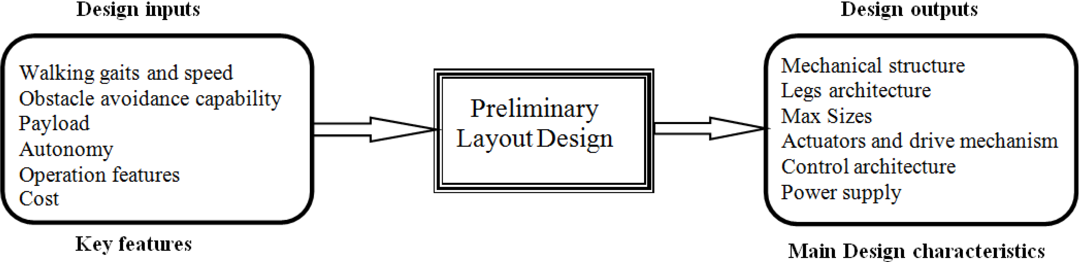
Designing hexapod legged robots is far from trivial. A very numerous and a wide range of possibilities exist to design a hexapod as also described in the previous section. Designers must take several decisions which influence the operation and technical features. Some of the most important design issues and constraints according to [48] can be outlined as:
- the mechanical structure of robot body;
- leg architecture;
- max sizes;
- actuators and drive mechanisms;
- control architecture;
- power supply;
- walking gaits and speed;
- obstacle avoidance capability;
- payload;
- autonomy;
- operation features;
- cost.
The above mentioned design issues and constraints can be classified as design input (or key features) and design output (or main design characteristics) as shown in the scheme of Figure 3.
Figure 3.
A scheme for preliminary layout design of hexapod walking robots.

A survey on the state of the art shows that each hexapod walking robot design is almost unique. Hexapod can be developed in several configurations and every solution has its design criteria, specifications, shapes, advantages and disadvantages, but the literature is lacking a systematic design procedure for hexapod robots as referring to specific functional requirements.
A preliminary design is often a trade-off solution between design requirements and key features. Possible aids for the preliminary design process can be given by the Quality Function Deployment [49] in order to define the relationship between the design configuration and the robot capabilities or requirements. Based on this approach, we propose a novel simplified procedure that can be used to relate and prioritize preliminary layout design to key features through numerical ranking.
As a first step, the key features will be identified and then ranked by their importance to the project. Table 2 gives the ranking criteria proposed. Rankings values are recorded in the importance rating column of Table 3. Table 4 gives the criteria used to evaluate the importance of an engineering solution in fulfilling key features. The relationship matrix in Table 3 is completed by filling the row column intersection (key features—design requirements) according to Table 4 criteria.
| Importance of Key Features | Value |
|---|---|
| Not important to project success | 1 |
| Somewhat important to project success | 2 |
| Fairly important to project success | 3 |
| Very important to project success | 4 |
| Critical to project: design driver | 5 |
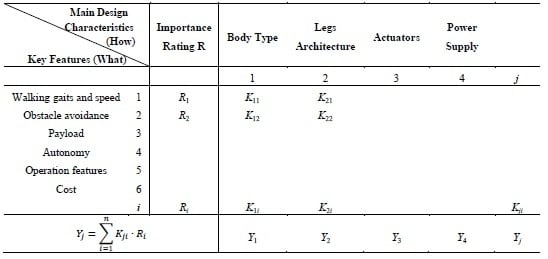
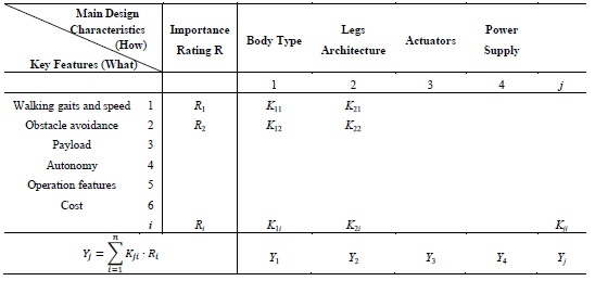
| Main Design Characteristics (How) | Importance Rating R | Body Type | Legs Architecture | Actuators | Power Supply | |||
|---|---|---|---|---|---|---|---|---|
| Key Features (What) | ||||||||
| 1 | 2 | 3 | 4 | j | ||||
| Walking gaits and speed | 1 | R1 | K11 | K21 | ||||
| Obstacle avoidance | 2 | R2 | K12 | K22 | ||||
| Payload | 3 | |||||||
| Autonomy | 4 | |||||||
| Operation features | 5 | |||||||
| Cost | 6 | |||||||
| i | Ri | K1i | K2i | Kji | ||||
Yj =  | Y1 | Y2 | Y3 | Y4 | Yj | |||
| Engineering Solution Satisfies the Requirement | Value |
|---|---|
| By itself | 9 |
| In conjunction with one or two factors | 3 |
| In conjunction with many other factors | 1 |
| Does not satisfy the requirements | 0 |
After filling in the relationship matrix, the importance rankings are multiplied by the relationship value and computed on each column of the matrix according to the rule of Table 3. The bottom of each column Yj gives the importance rating of engineering requirements. Results are a Pareto of main design characteristics, which can be used as a starting point in the choice of hexapod architecture. This tool will help to focus the process development on the issues that are most critical to the proposed hexapod design.
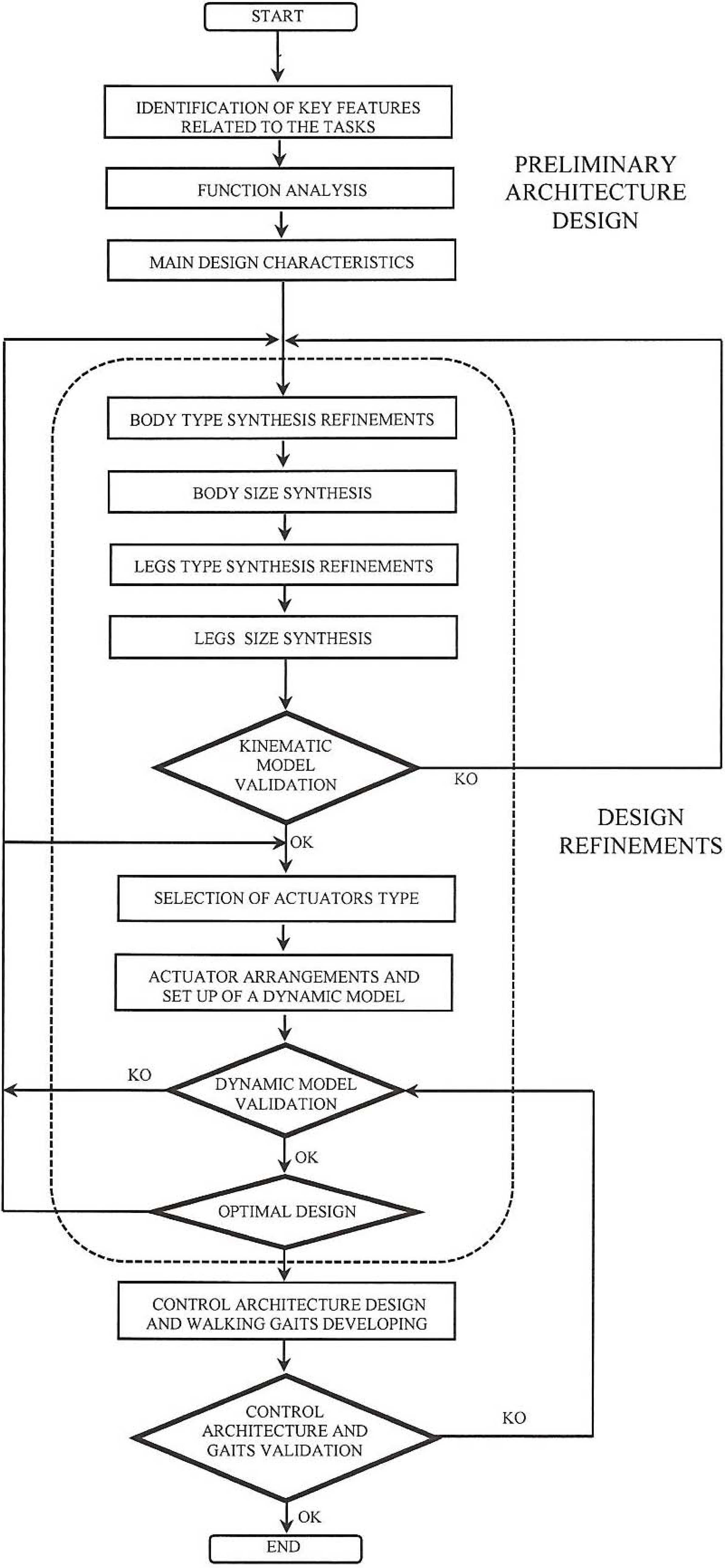
A practical example of the proposed procedure is provided in Section 4. The proposed procedure is an aid to select the most favorable preliminary design solution among those under consideration. Non-conventional design solutions can be also considered into the cause and effect matrix, provided that proper relationship values can be estimated. Figure 4 depicted a flow-chart of proposed design in order to systematically consider the main design characteristics and key features.
Figure 4.
Hexapod robot design flow-chart.

In the following, the main design characteristics and modeling issues are discussed in order to show how the proposed design procedure can be implemented. It is worth mentioning also that other design characteristics exist and additional features can be considered for specific applications. Thus, the most remarkable design characteristics have been considered as examples for filling in the data in the cause and effect matrix.
3.1. Robot Body Architecture
There are two basic architectures of hexapod robots: rectangular and hexagonal. The first one has six legs distributed symmetrically along two sides, each side having three legs. The second has legs distributed axi-symmetrically around the body, in a hexagonal or circular shape [50]. Many references can be found in the literature on rectangular six-legged robots. In [51], Lee et al. describe the longitudinal stability margin for rectangular hexapods. Also, the feasible walking gaits have been widely investigated and tested [52,53]. Bilateral symmetry may be better suited than radial symmetry to move along a straight line. Rectangular architectures require a special gait for turning action; generally, they need four steps in order to realize a turning action [50].
Hexagonal hexapod robots demonstrate better performances than rectangular robots for some aspects. As example hexagonal robots can have many kinds of gaits and can easily change direction—in fact true radial symmetry implies that all legs are equal and the body has no “front” or “rear”—there is thus no preferential direction for the motion. In [54], Preumont et al., proved that hexagonal hexapods can easily steer in all directions and that they have a longer stability margin. In [55], Takahashi et al., found that hexagonal robots rotate and move in all directions at the same time, better than rectangular ones, by comparing stability margin and stroke in wave gait. Chu and Pang in [56] proved theoretically that hexagonal hexapod robots have superior stability margin, stride and turning ability compared to rectangular robots.
3.2. Kinematic Architectures of Legs
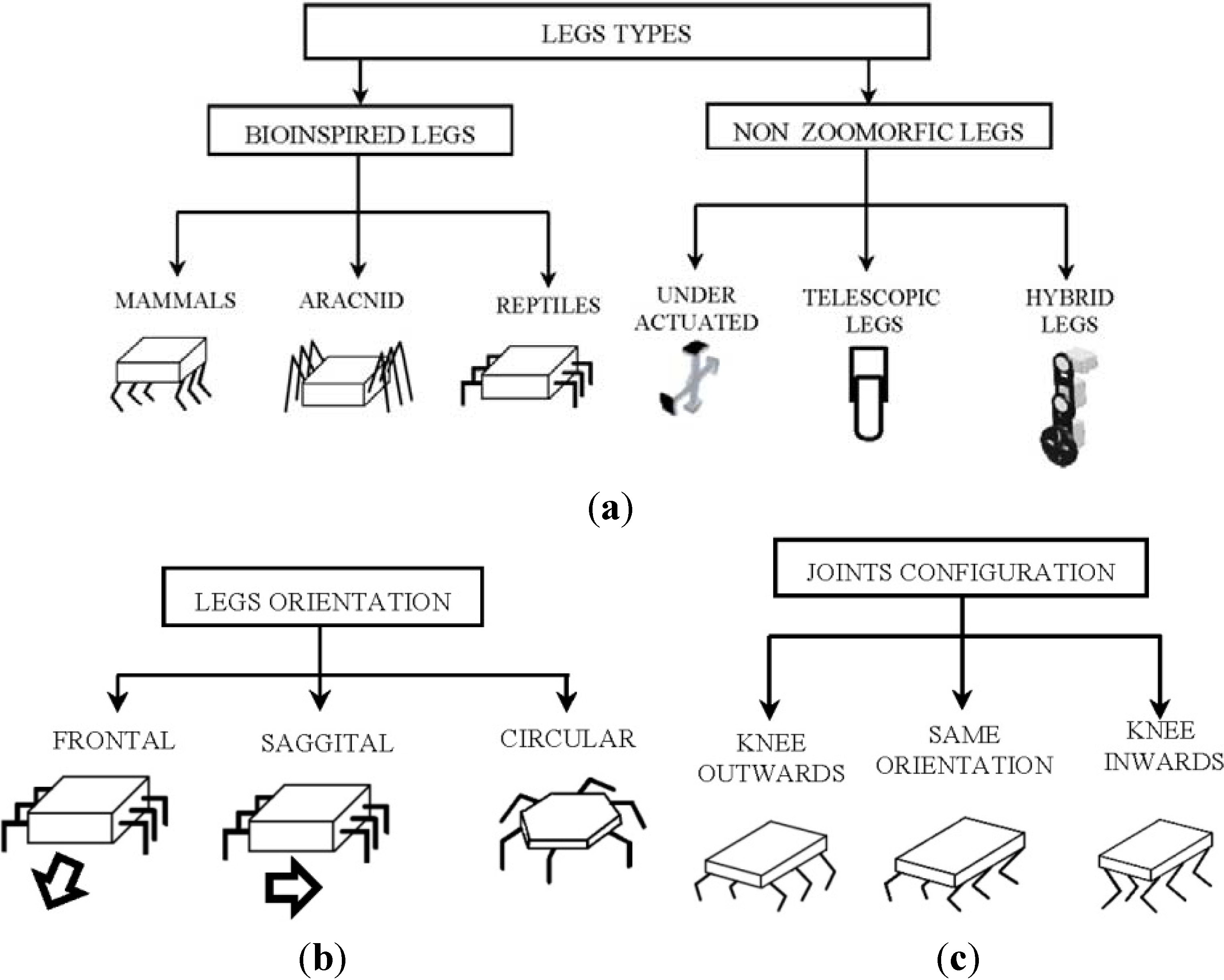
Kinematics architecture depends on the factors related to the application in which the hexapod robot is required for, as for example the terrain form, the workspace, and the payload. Literature shows that there is a number of different leg types currently employed for hexapod walking robots. All have advantages and disadvantages. Figure 5a shows a schematic classification of hexapod legs types. At the first stage, one can choose between bio inspired and non-zoomorphic legs. Bio inspired leg configuration is motivated primarily by animal gait, such as reptiles, mammals or arachnid. The first one has legs and bodies for moving over rough and uneven terrains [57]. The principal characteristic of the Reptilian type is that the legs are placed on both ends of the protruding body and knees to the side of the base. Mammals’ bodies are above the legs, which gives less support to the base and lower power consumption is needed to support the body, but it requires more stability than other types of animals [26]. In Aracnid configuration, legs extremities are situated on both sides, sticking the knees at the top of the spider’s body. The orientation of the legs in respect to the body of the hexapod robot can be done with three configurations (Figure 5b): frontal, sagittal or circular. In the first one, the directions are perpendicular to the advancement of the legs’ position, unlike the sagittal, which moves parallel to the robot legs, while in the circular arrangement the legs are positioned radially to the body of the system allowing the mechanism to move in any direction [58]. In the mammalian configuration, the legs are below the body and can place the knees in different positions depending on the application it requires (Figure 5c). Non zoomorphic legs can be hybrids such as in [59], telescopic such as in [24], or under-actuated such as in [28]. In [60], a solution named Roller-Walker is presented. The principle through which the robot propels itself during wheeled locomotion is the same as that of the skaters.
Figure 5.
Type setting of hexapod legs’ design.

3.2.1. Actuator Types
Many kinds of actuators can be employed for operating hexapod walking robots. The majority of hexapods is actuated by electric rotating motors, as they are relatively cheap, easy to control and there are suitable technologies to store the energy. Linear motors are able to generate considerable forces at very considerable speeds. However, these do not yet appear to have been utilized in many hexapods since they have a limited movable range to weight ratio. Pneumatics actuators have very low stiffness, inaccurate response, and low power to weight ratio. Pneumatics actuators, or air muscle, are able to offer a fast response time but they need an on-board air supply as bottles or compressors that are heavy pieces of equipment. Hydraulics actuators have high power/weight ratio; they are able to supply very high force, but suffer from the serious drawback of having to carry an engine to drive the pump. Hydraulics actuators are suitable for larger sized hexapod robots [61].
Unconventional actuators for hexapod robots can also be materials that can change shape through the direct application of electricity or a chemical agent. Ionic polymer-metal composites, for example, are materials that exhibit high strains under applied voltage differences allowing them to change from a sheet shape into curved shapes. Polyacrylonitrile is a form of artificial silk, classed as a gel polymer. It can respond fast, but the activation method is a change in pH, which requires the fibers to be housed in a watertight bag. Another class of materials that can change shape under the application of electricity is the Shape Memory Alloys (SMA), such as a nickel-titanium alloy that exhibits extreme contraction when heated. Contraction rates are controlled by the heating and cooling; the major drawback resulting in slow response times and small operating forces. Thus, despite a great research interest and the building of some prototypes such as in [62], the uses of SMA as hexapod actuators have been very limited. Present trends indicate that they are more suited to micro robots.
3.2.2. Actuators Arrangements
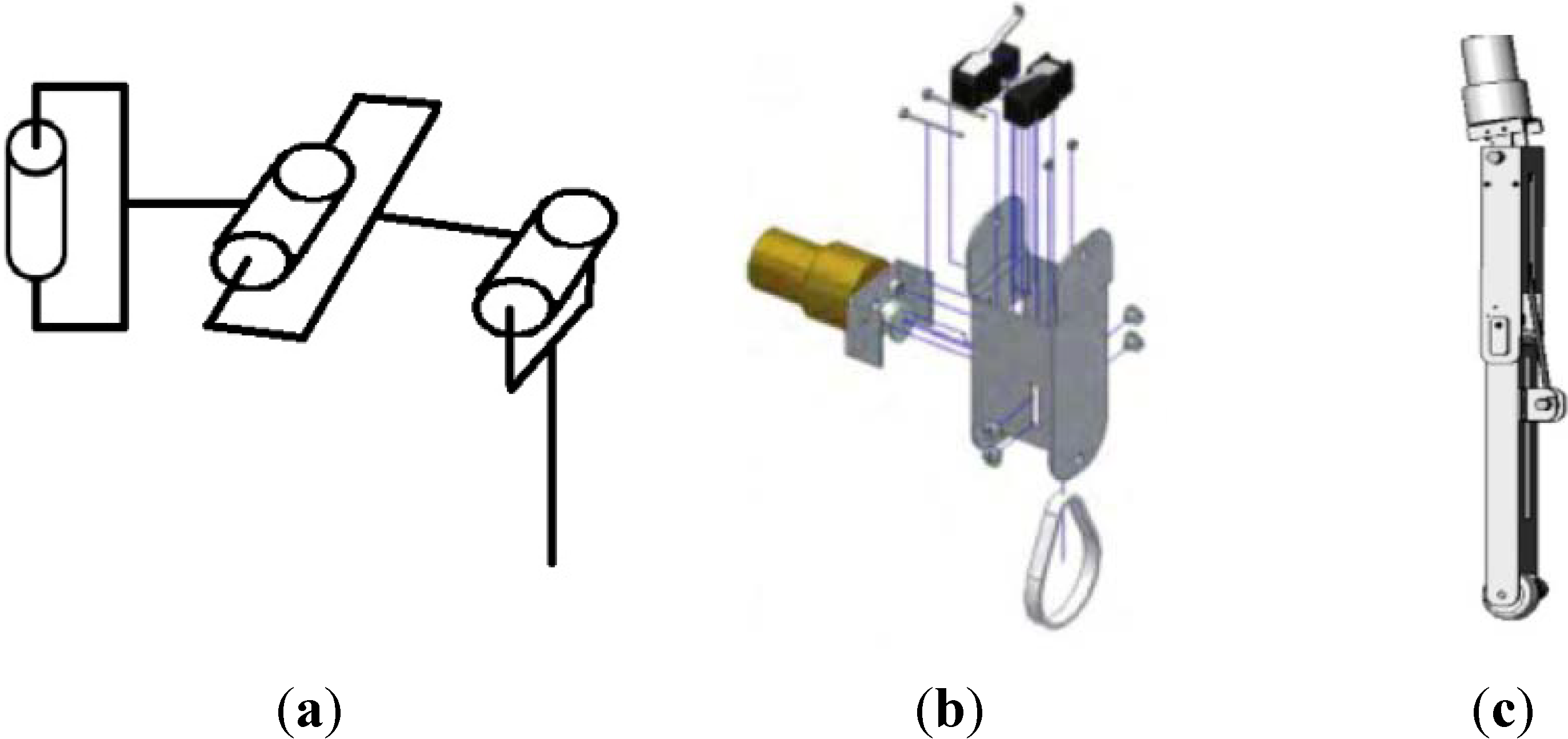
Typically, specific actuator arrangements are developed in order to obtain maximum leg workspace with a minimal kinematic structure. Several types of geometrical arrangements such as in Figure 6a are recurrent in literature. The design consists of links connected through knee joints. The walking motion is accomplished by controlling the angle of the links to position the feet.
Figure 6.
Actuators arrangement: (a) three DoF solution; (b) pinion-belt arrangement; (c) lead screw leg.
Figure 6.
Actuators arrangement: (a) three DoF solution; (b) pinion-belt arrangement; (c) lead screw leg.

There are a number of different ways in which the joints can be actuated, which are referenced in [48]. Options include mounting the motor at the joint itself, or using a pulley and belt (Figure 6b) or lead screw (Figure 6c) to set the angle of the knee using an actuator mounted near the base of the leg [59]. The major drawback of last design is the necessity to actuate remote joints. On the other hand, latching the actuator at the knee joint adds various dynamic effects to the leg which have to be compensated by the controller. This adds complexity to the control algorithms needed to move the leg. It also requires more powerful motors at the hip joint to move the added mass of the leg. Remote actuation, in which the actuators are located at the base of the leg, eliminates some of these problems, at the cost of increasing the complexity of the mechanism. The coupling of the motion of the end effector relative to the actuators is another undesirable characteristic of this leg design.
Another potential leg design is modeled according to a typical mammalian leg with a four-bar linkage structure. The major drawback of this design is that the motions are highly coupled and the effective workspace is somewhat limited. Moreover, the entire weight of the robot is supported by the hip joint and they necessitate a powerful and expensive motor.
3.3. Modeling Issues
Computational programs dedicated to the kinematic and dynamic analysis of mechanical systems are a powerful alternative to the classic design methods. Simulation-based design can help in the development and the characterization of hexapod robots. Simulation software allows testing design performance and predicting component’s behavior, prior to building a physical prototype. Simulation can also help the development of gait algorithms and the gait optimization.
Basically, the modeling of hexapod robots is composed of two steps. The first one concerns the kinematics of the robot motion: several types of software may be suitable for this purpose such as SolidWorks. The second stage of the model concerns dynamics and control of the actuators. This model is completed by the relevant forces encountered by walking robots, that is to say, the ground contact forces, the friction in the joints, the motor torques. Interaction of hexapod robots with the environment is a further step of the design study. Many references can be found in the literature as in [63]. Indeed, it is commonly acknowledged that high-geared actuators typically encountered in legged robots have very little sensitivity to inertia, and centrifugal and Coriolis forces. However, high-geared motors introduce flexibility, backlash and friction, which should be modeled to get reliable simulations. The development of gait algorithms can be initially based on pure kinematic robot models such as in [64,65] since hexapods are generally slow machines, and consequently inertial forces are not so important in the gait planning. A further aspect relates to gait optimization, which is focused, for example, on energy saving [66].
3.4. Optimal Design
The optimum design can be formulated as a multiobjective optimization problem in the form proposed in reference [67], as:
subjected to
where min is the operator for calculating the minimum of a vector function F(X); similarly max determines the maximum value among the N functions [wifi(X)] at each iteration; G(X) is the vector of constraint functions that describes limiting conditions, and H(X) is the vector of constraint functions that describes design prescriptions; X is the vector of design variables. The proposed optimization formulation uses the objective function F(X) at each iteration by choosing the worst-case value among all the scalar objective functions for minimizing it in the next iteration, as outlined in reference [68]. In particular, the worst-case value is selected in Equation (5) at each iteration as the objective function with maximum value among the N available objective functions. This approach for solving multi-objective problems with several objective functions and complex tradeoffs among them is known as the “minimax method”. The “minimax method” is widely indicated in the literature for many problems, like, for example, for estimating model parameters by minimizing the maximum difference between model output and design specification, as outlined in references [69,70].
min [F(X)] = min {max [wifi(X)]}
X X i = 1,…,N
X X i = 1,…,N
G(X) < 0
H(X) = 0
Since the formulated design problem is intrinsically highly non-linear, a solution is obtained when the numerical evolution from a tentative solution converges because of the iterative process to a solution that can be considered optimal within the explored range of the design variable domain. Therefore, a solution can be considered an optimal design as a local optimum, in general terms. This last remark makes clear the influence of a suitable formulation with computational efficiency for the involved criteria and constraints in order to have a design procedure, which is significant from an engineering viewpoint as well as being numerically efficient.
3.5. Hexapod Walking Robot Control
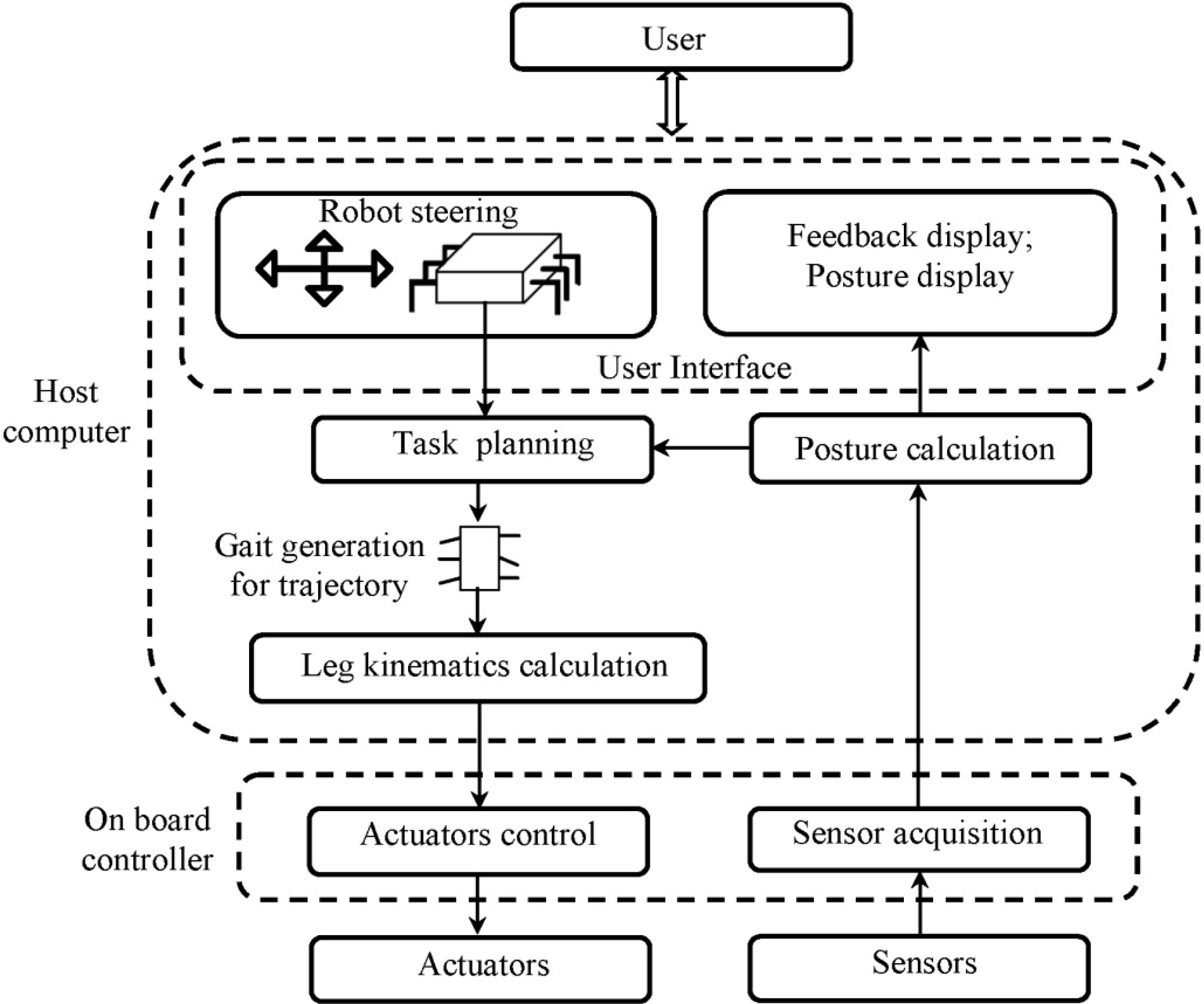
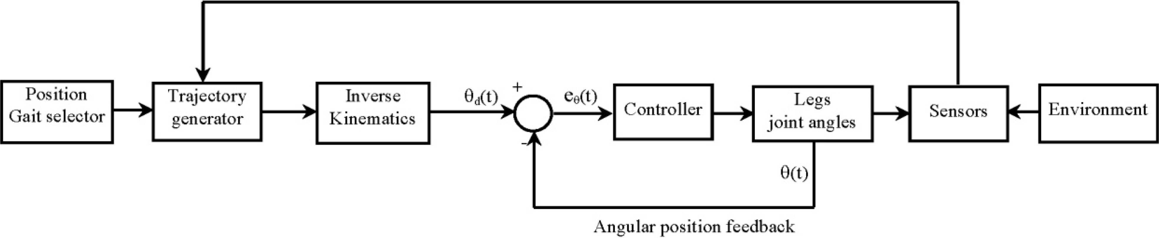
The control systems of recent hexapod robots are distributed hierarchical systems composed of a host computer, an onboard controller and various actuators and sensors. An example of hierarchical control architecture is shown in Figure 7. A schematic of hexapod basic locomotion control is shown in Figure 8. The user will set a desired position and walking gait, which is the input for the trajectory generator. The trajectory generator sends the leg coordinates to the inverse kinematic model for each leg. The inverse kinematic model re-calculates those given coordinates into its angular coordinates for all the joints. The outcomes of the inverse kinematics model are the joint angles which will then enter the control loop. The control at the joint level is almost always implemented using a PID control [71].
Figure 7.
An example of hierarchical control architecture for Hexapod robot.

Figure 8.
A scheme of hexapod robot basic locomotion control.

3.6. Gait Planning
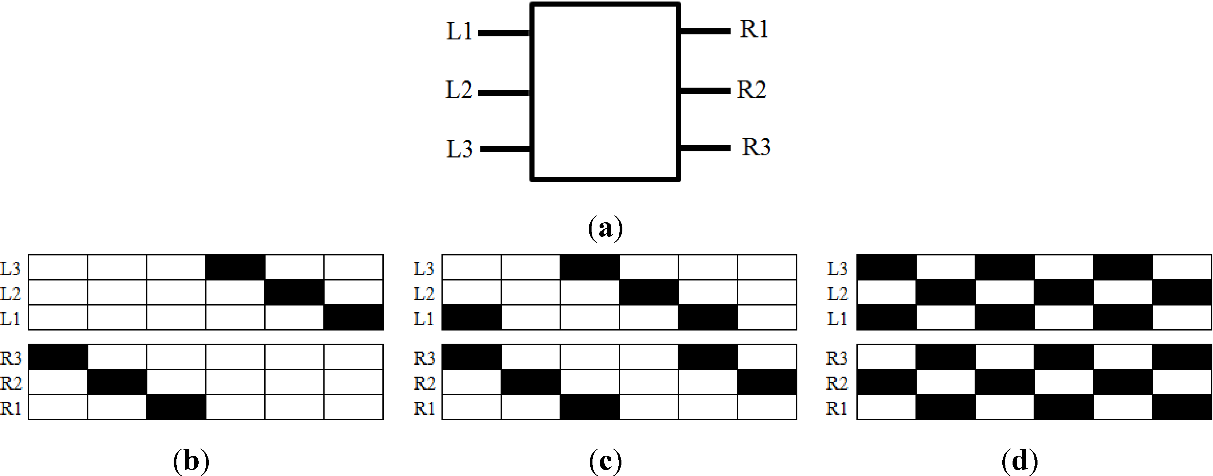
A gait is a sequence of leg motions coordinated with a sequence of body motions for moving the overall body of the robot in the desired direction and for orientation from one place to another. A gait is described as periodic when similar states of the same leg during successive strokes occur at the same interval for all legs. Periodic gaits are suitable for smooth terrain and they have been studied by several investigators, such as [72]. Figure 9 shows the scheme of some periodical hexapodal gaits; white color indicates that the foot is in ground contact and the black color otherwise, according to [73]. Figure 9a reports the hexapod legs’ description.
Figure 9.
Gait diagram of hexapodal gaits: (a) legs description; (b) metachronal gait; (c) ripple gait; (d) tripod gait.
Figure 9.
Gait diagram of hexapodal gaits: (a) legs description; (b) metachronal gait; (c) ripple gait; (d) tripod gait.

The metachronal gait illustrated in Figure 9b is adopted by the hexapod when it moves slowly. All legs on one side are moved forward in succession, starting with the rear-most leg. This is then repeated on the other side. Since only one leg is ever lifted at a time, with the other five down, the hexapod is always in a highly-stable posture. The ripple gait is used by the hexapod to move with a medium speed. Gait diagram representation is shown in Figure 9c. Tripod gait (Figure 9d) is a regular, periodic gait where β = 0.5, and where the anterior and posterior legs on one side lift in time with the contralateral middle leg, forming alternating tripods. This is a gait suitable for high speed walking over relatively flat ground.
One problem with periodic gaits is that they require synchronization between the expected and actual times that legs make contact with the ground. Over uneven ground, the time of footfall becomes unpredictable, breaking the rigorously defined leg phasing and compromising stability. The free gait, on the other hand, is much more effective on rough terrain with obstacles. The free gait is when each leg can move on a free chosen interval and its own stroke algorithm. Some examples can be found in the literature such as [74,75,76,77]. The difficulty with these approaches is the computational complexity. Genetic Algorithms (GA) are mostly used for free gait implementation [78]. Another way for using GA is a fuzzy logic controller, a potential tool for handling imprecision and uncertainty [79]. Also, using the techniques of soft computing will improve the leg speed; this is done by on-line trajectory generation [80]. Most of the studies focused on the control at the leg level and leg coordination using neural networks and fuzzy logic are based also on hybrid force/position control.
4. A Case of Study for Preliminary Lay-Out Design
This section describes the preliminary design process for a hexapod robot aimed for inspection and analysis of historical sites of architectonic interest, with low-cost and easy-operation features.
Key feature requirements for the specific application can be summarized as follows:
- low cost ( <1000 Euros);
- user-friendly operation, also for non-expert users (e.g., architects);
- possibility to negotiate a large variety of obstacles, such as
- -
- a step with maximum height of 60 mm;
- -
- a crest with maximum width of 100 mm and maximum height of 60 mm;
- -
- a ditch with a maximum width of 60 mm;
- the robot must be able to move inside archaeological and/or architectural sites by carrying surveying devices and by avoiding damage of the surface and other parts of the site;
- the robot can be operating wirelessly, in environments that cannot be reached or that are unsafe for human operators;
- operating speed on regular terrain should be >0.1 m/s on regular terrain and ≥0.01 m/s on uneven terrains as based on previous experience in architectonical survey.
According to the above referenced criteria, Table 5 shows a matrix related to preliminary design. As a first step, the key features are ranked by their importance to the project, according to Table 2. Each key feature has been detailed in several aspects. For example, walking speed has been described in terms of performances on regular terrain and uneven terrain. The cost has been divided according to two factors: total budget and possibility of use for commercial components. Regarding the walking gait, three types of gaits have been considered. In a similar way, all key features have been recorded in the rows of the matrix. Rankings are recorded in the second column of Table 5. Similarly, each design requirement has been divided into several categories. For example, the body type category reports two solutions: the first one is a rectangular shape and the second one is a hexagonal shape. The leg type issue has been split into three categories: configuration, orientation and knee. Configuration of legs has been categorized in mammals, reptile, spider and hybrid. Orientation of legs can be sagittal, frontal, and circular. In the same way, the knee item has been divided into three categories: outwards, same orientation and inwards. After the rankings have been chosen, the relationship matrix has been completed according to criteria given in Table 3 and the above mentioned design issues.
In the following, we explain, for example, how to fill row 5 of the matrix regarding the step avoidance category. Step avoidance Hmax ≥ 60 mm is a very important key feature, thus its importance ranking is 4. Regarding the shape, rectangular or hexagonal, the score is 3 since each of the solutions satisfies the obstacle avoidance requirement only in conjunction with one or two features. Mammalians’ configuration score is 9, since this solution demonstrated very good ability for obstacle traversing due to the high center of gravity. Reptile leg score is 1 since this solutions satisfies the requirements only in conjunction with many other factors. In the same way, spider leg configuration score is 1. Referring to [81,82], the hybrid legs score is 9, similarly to mammalian configuration. As regards the legs’ orientation, sagittal score is 1 since this solution is not effective in satisfying the obstacle avoidance requirement. Frontal orientation score is 3 since this solution satisfies the requirements only in conjunction with one or two factors. In the same way, circular orientation score is 3. Knee orientation score is 3 for the outwards solution, since it can satisfy the requirements only in conjunction with one or two factors. In the same way, orientation solution score is 9 due to the high center of gravity. Inward solution score is 1 since this solutions satisfies the requirements only in conjunction with many other factor. Regarding the actuators, the score for each item is 1 since each of them satisfies the requirement only in conjunction with many other factors. The same procedure holds for filling all the matrix rows.
After filling in the relationship matrix, the importance rankings have been multiplied by the relationship value and the total is given at the bottom of each column of the matrix. Thus, the value at the bottom of the column gives the importance rating of the considered main design characteristics. These evaluations must be confirmed with simulation and trade-off studies; however, only the highest ranked items are subject to design refinements. This will significantly reduce the required time investment for the design.
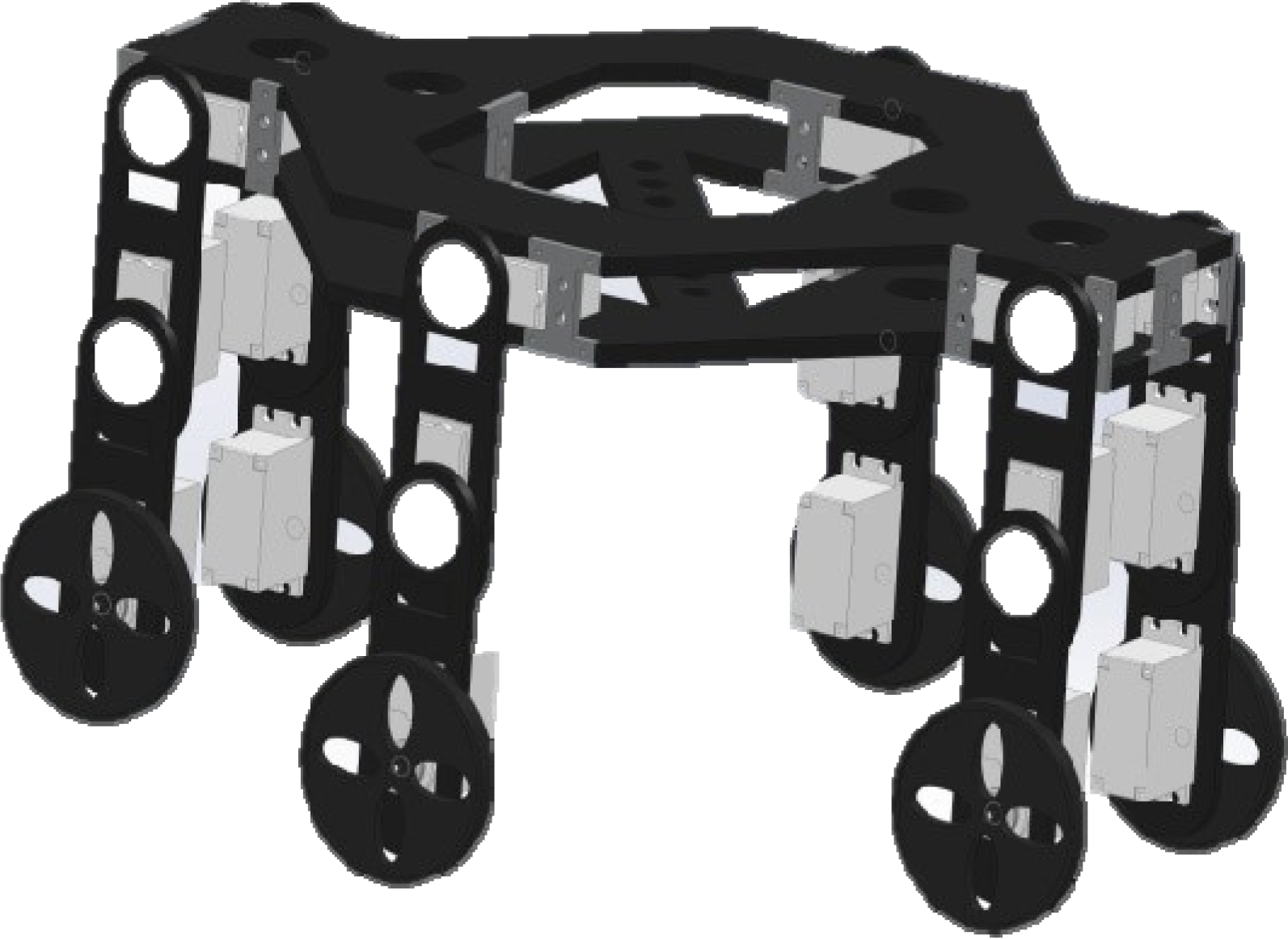
Final results in Table 5 show that the most significant engineering requirements are rectangular body shape, hybrid legs, frontal configuration, same knee orientation, and electrical actuators. In fact, the above mentioned characteristics have obtained the highest ranking in their category of the matrix (value 218, 294, 174, 200, 292, respectively). According to these results, the preliminary hexapod architecture has been selected. Based on the results of this preliminary design procedure, a 3D CAD model has been developed as shown in Figure 10. Design refinements and a prototype will be developed in the near future as final validation of the proposed approach.
Figure 10.
A CAD model of a novel hexapod.

| Main Design Characteristics (How) | Rating of Importance R | Body Type | Legs Type Synthesis | Actuators | ||||||||||||||
|---|---|---|---|---|---|---|---|---|---|---|---|---|---|---|---|---|---|---|
| Rectangular Shape | Hexagonal Shape | Configuration | Orientation | Knee | Electrical | Pneumatic | Hydraulics | |||||||||||
| Mammalian Legs | Reptile Legs | Spider Legs | Hybrid Legs | Sagittal | Frontal | Circular | Outwards | Same Orientation | Inwards | |||||||||
| 1 | 2 | 3 | 4 | 5 | 6 | 7 | 8 | 9 | 10 | 11 | 12 | 13 | 14 | 15 | ||||
| Walking speed | ||||||||||||||||||
| Regular terrain ≥ 0.1 m/s | 1 | 5 | 3 | 3 | 1 | 1 | 1 | 9 | 3 | 9 | 3 | 3 | 3 | 3 | 9 | 3 | 3 | |
| Uneven terrain ≥ 0.01 m/s | 2 | 3 | 3 | 3 | 1 | 1 | 1 | 3 | 3 | 9 | 3 | 3 | 3 | 3 | 9 | 3 | 3 | |
| Low Cost | ||||||||||||||||||
| Cost ≤ 1000 Euro | 3 | 5 | 3 | 3 | 3 | 3 | 3 | 3 | 1 | 1 | 1 | 1 | 1 | 1 | 9 | 1 | 1 | |
| Use of commercial components | 4 | 4 | 3 | 1 | 9 | 9 | 9 | 9 | 3 | 3 | 3 | 3 | 3 | 3 | 9 | 3 | 1 | |
| Obstacle avoidance | ||||||||||||||||||
| Step Hmax ≥ 60 mm | 5 | 4 | 3 | 3 | 9 | 1 | 1 | 9 | 1 | 3 | 3 | 3 | 9 | 1 | 1 | 1 | 1 | |
| Crest Hmax ≥ 60 mm W ≥ 100 mm | 6 | 4 | 3 | 3 | 9 | 1 | 1 | 9 | 1 | 3 | 3 | 3 | 9 | 1 | 1 | 1 | 1 | |
| Ditch Wmax ≥ 100 mm | 7 | 4 | 3 | 3 | 9 | 1 | 1 | 9 | 1 | 3 | 3 | 3 | 9 | 1 | 1 | 1 | 1 | |
| Operation | ||||||||||||||||||
| Wireless | 8 | 5 | 3 | 3 | 3 | 1 | 1 | 1 | 1 | 1 | 1 | 1 | 1 | 1 | 9 | 1 | 1 | |
| Omnidirectional Steering | 9 | 4 | 3 | 3 | 1 | 3 | 3 | 3 | 3 | 3 | 9 | 3 | 3 | 3 | 3 | 3 | 3 | |
| Autonomy ≥ 1 h | 10 | 5 | 1 | 1 | 1 | 1 | 1 | 1 | 1 | 1 | 1 | 1 | 1 | 1 | 9 | 0 | 0 | |
| Walking Gait | ||||||||||||||||||
| Tripod gait | 11 | 3 | 9 | 9 | 3 | 3 | 3 | 9 | 3 | 3 | 3 | 3 | 3 | 3 | 1 | 1 | 1 | |
| Metachronal gait | 12 | 3 | 9 | 3 | 3 | 3 | 3 | 3 | 9 | 3 | 3 | 3 | 3 | 3 | 1 | 1 | 1 | |
| Free gaits | 13 | 1 | 3 | 3 | 1 | 1 | 1 | 9 | 3 | 1 | 1 | 1 | 3 | 3 | 1 | 1 | 1 | |
| Ground clearance > 15 cm | 14 | 3 | 9 | 3 | 9 | 3 | 1 | 3 | 1 | 1 | 1 | 1 | 1 | 1 | 1 | 1 | 1 | |
| Load carrying capacity ≥ 0.5 kg | 15 | 5 | 3 | 3 | 1 | 1 | 1 | 1 | 1 | 1 | 1 | 1 | 1 | 1 | 3 | 3 | 3 | |
| Yj = | 218 | 174 | 242 | 126 | 120 | 294 | 122 | 174 | 150 | 126 | 200 | 104 | 292 | 95 | 87 | 87 | ||
5. Conclusions
This paper gives an overview of the state of the art on six-leg walking robots. Careful attention is paid to the main design issues and constraints that influence the technical feasibility and performance of these systems. A design procedure is outlined in order to systematically design a six-leg walking robot. In particular, the proposed design procedure takes into account the mechanical structure and leg configuration, the actuating and drive mechanisms, payload, motion conditions, and walking gait, providing a useful tool for the systematic choice of main design characteristic. A case study has been reported in order to show the effectiveness and engineering feasibility of the proposed procedure.
Acknowledgments
Authors wish to acknowledge the fruitful discussions and support given by Prof. Marco Ceccarelli, director of LARM Laboratory.
Author Contributions
Franco Tedeschi has systematized the proposed design procedure within his PhD studies under the supervision of Giuseppe Carbone. Basic concepts and design features of “Cassino Hexapod” prototype series have been proposed by Giuseppe Carbone.
Conflicts of Interest
The authors declare no conflict of interest.
References
- Chàvez-Clemente, D. Gait Optimization for Multi-legged Walking Robots, with Application to a Lunar Hexapod. Ph.D. Thesis, Stanford University, California, CA, USA, 2011. [Google Scholar]
- Carbone, G.; Ceccarelli, M. Legged robotic systems. In Cutting Edge Robotics; Kordic, V., Lazinica, A., Merdan, M., Eds.; InTech: Vienna, Austria, 2005; pp. 553–576. [Google Scholar]
- Cigola, M.; Pelliccio, A.; Salotto, O.; Carbone, G.; Ottaviano, E.; Ceccarelli, M. Application of robots for inspection and restoration of historical sites. In Proceedings of the International Symposium on Automation and Robotics in Construction of the Conference, Ferrara, Italy, 11–14 September 2005; p. 37.
- Jun, B.H.; Shim, H.; Kim, B.; Park, J.Y.; Baek, H.; Yoo, S.; Lee, P.M. Development of seabed walking robot CR200. In Proceedings of the OCEANS’13 MTS/IEEE of the Conference, San Diego, CA, USA, 23–26 September 2013; pp. 1–5.
- Georgiades, C. Simulation and Control of an Underwater Hexapod Robot. M.D. Thesis, McGill University, Montreal, QC, Canada, 2005. [Google Scholar]
- Bares, J.; Hebert, M.; Kanade, T.; Krotkov, E.; Mitchell, T.; Simmons, R.; Whittaker, W. Ambler: An autonomous rover for planetary exploration. IEEE Comput. 1989, 26, 6–18. [Google Scholar]
- Preumont, A.; Alexandre, P.; Doroftei, I.; Goffin, F. A conceptual walking vehicle for planetary exploration. Mechatronics 1997, 7, 287–296. [Google Scholar]
- Bartholet, T.; Crawson, R. Robot Applications for Nuclear Power Plant Maintenance; EPRI Report-NP-3941, Research Report Center: Palo Alto, CA, USA, 1985. [Google Scholar]
- Oku, M.; Yang, H.; Paio, G.; Harada, Y.; Adachi, K.; Barai, R.; Nonami, K. Development of hydraulically actuated hexapod robot COMET-IV-The 1st report: System design and configuration. In Proceedings of the 2007 JSME Conference on Robotics and Mechatronics, Akita, Japan, 26–28 May 2007.
- Gregorio, P.; Ahmadi, M.; Buehler, M. Design, control, and energetics of an electrically actuated legged robot. Syst. Man Cybern. B IEEE Trans. 1997, 27, 626–634. [Google Scholar] [CrossRef]
- Schneider, A.; Schmucker, U. Force sensing for multi-legged walking robots: Theory and experiments part 1: Overview and force sensing. In Mobile Robotics, Moving Intelligence; Buchli, J., Ed.; Pro Literatur Verlag ARS: Germany; Austria, 2006; pp. 125–174. [Google Scholar]
- Peternella, M.; Salinari, S. Simulation by digital computer of walking machine control system. In Proceedings of the 5th IFAC Symposium on Automatic Control in Space of the Conference, Genova, Italy, June 1973.
- Okhotsimski, D.; Platonov, A. Control algorithm of the walking climbing over obstacles. In Proceedings of the 3rd International Joint Conference on Artificial Intelligence, Stanford, CA, USA, 20 August 1973.
- Gurfinkel, V.; Gurfinkel, E.; Devjanin, E.; Efremov, E.; Zhicharev, D.; Lensky, A.; Schneider, A.; Shtilman, L. Investigation of robotics. In Six-legged Walking Model of Vehicle with Supervisory Control; Nauka Press: Moscow, Russia, 1982; pp. 98–147. [Google Scholar]
- McGhee, R. Control of legged locomotion systems. In Proceedings of the 18th Automatic Control Conference, San Francisco, CA, USA, 3–8 December 1977; pp. 205–215.
- Raibert, M. Legged Robots that Balance; MIT Press: Cambridge, London, 1986; pp. 180–201. [Google Scholar]
- Byrd, J.; de Vries, K. A six-legged telerobot for nuclear applications development. Int. J. Robot. Res. 1990, 9, 43–52. [Google Scholar] [CrossRef]
- Efimov, V.; Kudriasev, M.; Titov, A. Investigation of robotics systems. In A Physical Similar of Motion Walking Apparatus; Nauka Press: Moscow, Russia, 1982; pp. 86–91. [Google Scholar]
- Song, S.M.; Waldron, K. Machines that Walk: The Adaptive Suspension Vehicle; MIT Press: Cambridge, London, 1989; pp. 283–299. [Google Scholar]
- Akozono, J.; Iwasaki, M.; Asakura, O. Development on a walking robot for underwater inspection. In Proceedings of the International Conference on Arabidopsis Research (ICAR’ 89), Columbus, OH, USA, 13–15 June 1989.
- Brooks, R.A. A robot that walks; emergent behaviors from a carefully evolved network. Neural Comput. 1989, 1, 253–262. [Google Scholar] [CrossRef]
- Bares, J.; Hebert, M.; Kande, T.; Krotkov, E.; Mitchell, T.; Simmons, R.; Whittaker, W. Ambler: An autonomous rover for planetary exploration. IEEE Comput. 1989, 22, 18–26. [Google Scholar] [CrossRef]
- Angle, C.A.; Brooks, R.A. Small planetary rovers. In Proceedings of the IEEE International Workshop on Intelligent Robots and Systems, Ibaraki, Japan, 3–6 July 1990; pp. 1–5.
- Pfeiffer, F.; Eltze, J.; Weidermann, H. Six-legged technical walking considering biological principles. Robot. Autom. 1995, 14, 223–232. [Google Scholar] [CrossRef]
- Nelson, G.M.; Quinn, R.D.; Bachmann, R.J.; Flannigan, W.C.; Ritzmann, R.E.; Watson, J.T. Design and simulation of a cockroach-like hexapod robot. In Proceedings of the 1997 IEEE International Conference on Robotics and Automation, Albuquerque, NM, USA, 25 April 1997; pp. 1106–1111.
- Delcomyn, F.; Nelson, M.E. Architectures for a biomimetic hexapod robot. Robot. Auton. Syst. 2000, 30, 5–15. [Google Scholar] [CrossRef]
- Fielding, M.R.; Dunlop, R.; Damaren, C.J. Hamlet: Force/Position controlled hexapod walker—Design and systems. In Proceedings of the IEEE Conference on Control Applications, Mexico City, Mexico, 5–9 September 2001; pp. 984–989.
- Saranli, U.; Buehler, M.; Koditschek, D.E. RHex—A simple and highly mobile hexapod robot. Int. J. Robot. Res. 2001, 20, 616–631. [Google Scholar] [CrossRef]
- Roennau, A.; Heppner, G.; Pfozter, L.; Dillman, R. Lauron V: Optimized leg configuration for the design of a bio-inspired walking robot. In Proceedings of the 16th International Conference on Climbing and Walking Robots and the Support Technologies for Mobile Machines, Sydney, Australia, 14–17 July 2013; pp. 563–571.
- Arena, P.; Fortuna, L.; Frasca, M.; Patanè, L.; Pavone, M. Implementation and experimental validation of an autonomous hexapod robot. In Proceedings of the IEEE International Symposium on Circuits and Systems, Kos, Greece, 21–24 May 2006.
- Cham, J.G.; Bailey, S.A.; Clark, J.E.; Full, R.J.; CutKosky, M.R. Fast and robust: Hexapedal robots via shape deposition manufacturing. Int. J. Robot. Res. 2002, 21, 869–882. [Google Scholar] [CrossRef]
- Lewinger, W.A.; Branicky, M.S.; Quinn, R.D. Insect-inspired, actively compliant hexapod capable of object manipulation. In Proceedings of the 8th International Conference on Climbing and Walking Robots (CLAWAR’ 2005), London, UK, 13–15 September 2005; pp. 65–72.
- Kennedy, B.; Okon, A.; Aghazarian, H.; Garrett, M.; Huntsberger, T.; Magnone, L.; Robinson, M.; Townsend, J. The lemur II-Class robots for inspection and maintenance of orbital structures: A system description. In Proceedings of the 8th International Conference on Climbing and Walking Robots (CLAWAR’ 2005), London, UK, 13–15 September 2005; pp. 1069–1076.
- Showalter, M. Hexapod Work Space and Walking Algorithm; VDM Verlag: Saarbrücken, Germany, 2009; pp. 20–34. [Google Scholar]
- Hauser, T.; Bretl, K.; Latombe, J.C.; Harada, W. Motion planning for legged robots on varied terrain. Int. J. Robot. Res. 2008, 27, 1325. [Google Scholar] [CrossRef]
- Georgiadis, C.; German, A.; Hogue, A.; Liu, H.; Prahacs, C.; Ripsman, A.; Sim, R.; Torres, L.A.; Zhang, P.; Buehler, M.; Dudek, G.; Jenkin, M.; Milios, E. AQUA: An aquatic walking robot. In Proceedings of the IEEE/RSJ International Conference on Intelligent Robots and Systems (IROS), Sendai, Japan, 28 September–2 October, 2004.
- Kang, H.; Shim, H.; Jun, B.H.; Lee, P.M. Design of underwater link and joint for the development of multi-legged underwater robot CR200. In Proceedings of the MTS/IEEE OCEANS 2012, Yeosu, Korea, 21–24 May 2012; pp. 1–6.
- Asbeck, A.T.; Kim, S.; McClung, A.; Parness, A.; Cutkosky, M.R. Climbing walls with microspines. In Proceedings of the IEEE International Conference Robotics and Automation, Orlando, FL, USA, 15–19 May 2006.
- Nonami, K.; Huang, Q.J. Humanitarian mine detection six-legged walking robot COMET-II with two manipulators. In Proceedings of the 4th International Conference on Climbing and Walking Robots (CLAWAR’ 2001), Karlsruhe, Germany, 24–26 September 2001; pp. 989–996.
- Mantis homepage. Available online: http://www.mantisrobot.com (accessed on 24 March 2014).
- Genta, G. Introduction to the Mechanics of Space Robots; Springer: Berlin, Germany, 2012; pp. 381–423. [Google Scholar]
- Song, S.M.; Choi, B.S. The optimally stable ranges of 2n-Legged wave gaits. IEEE Trans. Syst. Man Cybern. B 1990, 20, 888–902. [Google Scholar] [CrossRef]
- Alexander, R. McN. Exploring Biomechanics—Animals in Motion; W.H. Freeman Press: New York, NY, USA, 1992. [Google Scholar]
- Alexander, R. McN. The gait of bipedal and quadrupedal animals. Int. J. Robot. Res. 1984, 3, 49–59. [Google Scholar] [CrossRef]
- Gabrielli, G.; von Karman, T. What price speed—Specific power required for propulsion of vehicles. Mech. Eng. 1950, 72, 775–781. [Google Scholar]
- McGhee, R.B.; Frank, A.A. On the stability properties of quadruped creeping gaits. Math. Biosci. 1968, 3, 331–351. [Google Scholar] [CrossRef]
- Messuri, D.A.; Klein, C.A. Automatic body regulation for maintaining stability of a legged vehicle during rough-terrain locomotion. IEEE J. Robot. Autom. 1985, 1, 132–141. [Google Scholar] [CrossRef]
- Zielinska, T. Autonomous walking machines, discussion of the prototyping problems. Bulletin of the Polish academy of sciences. Tech. Sci. 2010, 58, 443–451. [Google Scholar]
- Rashid, M.Z.A.; Aras, M.S.M.; Radzak, A.A.; Kassim, A.M.; Jamali, A. Development of hexapod robot with manoeuvrable wheel. Int. J. Adv. Sci. Tech. 2012, 49, 119–136. [Google Scholar]
- Ding, X.; Wang, Z.; Rovetta, A.; Zhu, J.M. Locomotion analysis of hexapod robot. In Climbing and Walking Robots; In Tech: Rijeka, Croatia, 2010; pp. 291–310. [Google Scholar]
- Lee, T.T.; Liao, C.M.; Chen, T.K. On the stability properties of hexapod tripod gait. IEEE J. Robot. Autom. 1988, 4, 427–434. [Google Scholar] [CrossRef]
- Waldron, K.J.; McGhee, R.B. The adaptive suspension vehicle. IEEE Control Syst. Mag. 1986, 6, 7–12. [Google Scholar] [CrossRef]
- Wang, X.J. A Study of Locomotion and Force Planning for Multilegged Walking Robots. Ph.D. Thesis, Huazhong University of Science & Technology, Wuhan, China, 2005; pp. 95–100. [Google Scholar]
- Preumont, A.; Alexadre, P.; Ghuys, D. Gait analysis and implementation of a six leg walking machine. In Proceedings of the Fifth International Conference on Advanced Robotics. Robots in Unstructured Environments (ICAR’ 91), Pisa, Italy, 19–22 June 1991; Volume 2, pp. 941–945.
- Takahashi, Y.; Arai, T. Development of multi-limb robot with omnidirectional manipulability and mobility. In Proceedings of the 2000 IEEE-RSJ International Conference on Intelligent Robots and Systems, Takamatsu, Japan, 31 October–5 November 2000; Volume 3, pp. 2012–2017.
- Chu, S.K.-K.; Pang, G.K.-H. Comparison between different models of hexapod robot in fault-tolerant gait. IEEE Trans. Syst. Man Cybern. 2002, 32, 752–756. [Google Scholar] [CrossRef]
- Silva, M.F.; Tenreiro Machado, J.A. A historical perspective of legged robots. J. Vib. Control 2007, 13, 1447–1486. [Google Scholar] [CrossRef]
- Billah, M.M.; Ahmed, M.; Farhana, S. Walking hexapod robot in disaster recovery developing algorithm for terrain negotiation and navigation. In New Advanced Technologies; Lazinica, A., Ed.; In Tech: Rijeka, Croatia, 2010. [Google Scholar]
- Nava Rodríguez, N.E.; Carbone, G.; Ceccarelli, M.; Moreno Lorente, L.E. Design evolution of cassino hexapod robot. In Proceedings of the 10th Biennial ASME Conference on Engineering Systems Design and Analysis ESDA2010, Istanbul, Turkey, 12–14 July 2010.
- Endo, G.; Hirose, S. Study on Roller-Walker: System integration and basic experiments. Robot. Autom. 1999, 3, 2032–2037. [Google Scholar] [CrossRef]
- Nonami, K.; Barai, R.K.; Irawan, A.; Daud, M.R. Hydraulically Actuated Hexapod Robots; Springer: London, UK, 2014; pp. 78–104. [Google Scholar]
- Conrad, J.M.; Mills, J.W. The history and future of stiquito: A hexapod insectoid robot. In Artificial Life Models in Hardware; Springer: London, UK, 2009; pp. 1–20. [Google Scholar]
- Rahnejat, H. Multi-body dynamics: Historical evolution and application. J. Mech. Eng. Sci. 2000, 214, 149–173. [Google Scholar] [CrossRef] [Green Version]
- Salmi, S.; Halme, A. Implementing and testing a reasoning-based free gait algorithm in the six-legged walking machine MECANT. Control Eng. Pract. 1996, 4, 487–492. [Google Scholar] [CrossRef]
- Silva, M.F.; Tenreiro Machado, J.A. A Kinematic and dynamic performance analysis of artificial legged systems. Robotica 2008, 26, 19–39. [Google Scholar]
- De Santos, P.G.; Garcia, E.; Ponticelli, R.; Armada, M. Minimizing energy consumption in hexapod robots. Adv. Robot. 2009, 23, 681–704. [Google Scholar] [CrossRef]
- Grace, A. Optimization Toolbox User’s Guide; The MatlabWorks Inc.: Denver, CO, USA, 1992. [Google Scholar]
- Vanderplaats, G. Numerical Optimization Techniques for Engineers Design; McGraw-Hill: NewYork, NY, USA, 1984. [Google Scholar]
- Eldar, Y.C. Minimax estimation of deterministic parameters in linear models with a random model matrix. IEEE Trans. Signal Process. 2006, 54, 601–612. [Google Scholar] [CrossRef]
- Medanic, J.; Andjelic, M. Minimax solution of the multiple-target problem. IEEE Trans. Autom. Control 1972, 17, 597–604. [Google Scholar] [CrossRef]
- Franklin, G.F. Feedback Control of Dynamic Systems; Addison-Wesley Longman Publishing Co.: Boston, MA, USA, 2002. [Google Scholar]
- Collins, J.J.; Stewart, I. Hexapodal gaits and coupled nonlinear oscillator models. Biol. Cybern. 1993, 68, 287–298. [Google Scholar] [CrossRef]
- Song, S.M.; Waldron, K.J. An analytical approach for gait study and its applications on wave gaits. Int. J. Robot. Res. 1987, 6, 60–71. [Google Scholar] [CrossRef]
- Ferrell, C. Robust Agent Control of an Autonomous Robot with Many Sensors and Actuators; MIT AI Lab: Cambridge, MA, USA, Technical Report 1443; 1993; pp. 1–100. [Google Scholar]
- McGhee, R.B.; Iswandhi, G.I. Adaptive locomotion of a multilegged robot over rouch terrain. IEEE Trans. Syst. Man Cybern. 1979, 9, 176–182. [Google Scholar] [CrossRef]
- Shih, T.; Tsai, C.S.; Her, I. Comparison of alternative gaits for multiped robots with severed legs. Int. J. Adv. Robot. Syst. 2012, 9, 1–8. [Google Scholar]
- Silva, M.F.; Tenreiro Machado, J.A.; Lopes, A.M. Quasi-periodic Gaits in Multi-legged Robots. In Proceedings of the 5th International Conference on Climbing and Walking Robots and the Support Technologies for Mobile Machines (CLAWAR’ 2002), Paris, France, 25–27 September 2002; pp. 733–740.
- Goldberg, D.E. Genetic Algorithms in Search, Optimization, and Machine Learning; Addison-Wesley Longman Publishing Co.: Upper Saddle River, NJ, USA, 1989; pp. 110–130. [Google Scholar]
- Kosko, B. Neural Networks and Fuzzy Systems: A Dynamical Systems Approach to Machine Intelligence; Prentice-Hall, Inc.: Upper Saddle River, NJ, USA, 1992; pp. 179–193. [Google Scholar]
- Gonzalez de Santos, P.; Garcia, E.; Estremera, J. Quadrupedal Locomotion: An Introduction to the Control of Four-Legged Robots; Springer: London, UK, 2006. [Google Scholar]
- Carbone, G.; Ceccarelli, M. A mechanical design of a low-cost easy-operation anthropomorphic wheeled leg for walking machines. Int. J. Robot. Manag. 2004, 9, 3–8. [Google Scholar]
- Carbone, G.; Shrot, A.; Ceccarelli, M. Operation strategy for a low-cost easy-operation cassino hexapod. Appl. Bionics Biomech. 2007, 4, 149–156. [Google Scholar] [CrossRef]
© 2014 by the authors; licensee MDPI, Basel, Switzerland. This article is an open access article distributed under the terms and conditions of the Creative Commons Attribution license (http://creativecommons.org/licenses/by/3.0/).
Share and Cite
MDPI and ACS Style
Tedeschi, F.; Carbone, G. Design Issues for Hexapod Walking Robots. Robotics 2014, 3, 181-206. https://doi.org/10.3390/robotics3020181
AMA Style
Tedeschi F, Carbone G. Design Issues for Hexapod Walking Robots. Robotics. 2014; 3(2):181-206. https://doi.org/10.3390/robotics3020181
Chicago/Turabian StyleTedeschi, Franco, and Giuseppe Carbone. 2014. "Design Issues for Hexapod Walking Robots" Robotics 3, no. 2: 181-206. https://doi.org/10.3390/robotics3020181