
Design Guideline for Hydropower Plants Using One or Multiple Archimedes Screws


School of Engineering, University of Guelph, 50 Stone Rd E, Guelph, ON N1G 2W1, Canada
*
Author to whom correspondence should be addressed.
Processes 2021, 9(12), 2128; https://doi.org/10.3390/pr9122128
Submission received: 2 November 2021
/
Revised: 23 November 2021
/
Accepted: 24 November 2021
/
Published: 25 November 2021
(This article belongs to the Special Issue CFD Modelling and Simulation of Water Turbines)
Abstract
:The Archimedes/Archimedean screw generator (ASG) is a fish-friendly hydropower technology that could operate under a wide range of flow heads and flow rates and generate power from almost any flow, even wastewater. The simplicity and low maintenance requirements and costs make ASGs suitable even for remote or developing areas. However, there are no general and easy-to-use guidelines for designing Archimedes screw power plants. Therefore, this study addresses this important concern by offering a simple method for quick rough estimations of the number and geometry of Archimedes screws in considering the installation site properties, river flow characteristics, and technical considerations. Moreover, it updates the newest analytical method of designing ASGs by introducing an easier graphical approach that not only covers standard designs but also simplifies custom designs. Besides, a list of currently installed and operating industrial multi-Archimedes screw hydropower plants are provided to review and explore the common design properties between different manufacturers. On top of that, this study helps to improve one of the biggest burdens of small projects, the unscalable initial investigation costs, by enabling everyone to evaluate the possibilities of a green and renewable Archimedes screw hydropower generation where a flow is available.
1. Introduction
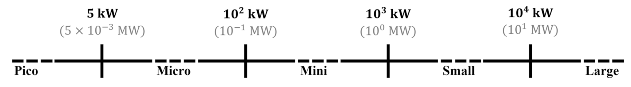
Hydropower is among the most efficient and reliable renewable energy resources [1] and offers significant value for a sustainable future [2]. Hydropower plants can be classified as in Figure 1 [3] based on the electrical generating capacity. It is estimated that small hydropower plants generate about 10% of global hydropower [3]. Hydropower plants that utilize the natural flow of water in a run-of-river (ROR) configuration [4] usually have small or no reservoirs. The lack of a large, actively-controlled reservoir minimizes flooding land and soil destruction, greenhouse gas emissions, as well as environmental [5] and social impacts [6]. However, the resulting reduction in control of river flow can result in more variable or poorly timed power generation [6].
The Archimedes/Archimedean screw was one of the earliest hydraulic machines [7]. It is made of one or more helical arrays of blades wrapped around a central cylinder [8] and supported within a fixed trough with a small gap that allows the screw to rotate freely [6]. Using Archimedes screws as water pumps dates back many centuries. As a modern application, Archimedes screw pumps (ASP) have been regularly used in wastewater treatment plants. The earliest patent involving using a screw in hydro power plants dates back to 1922 [9], but examples of application of Archimedes screw generator (ASG) technology date back only to the 1990s [10]. The Archimedes screw is theoretically a reversible hydraulic, and there are examples of single installations where screws can be used alternately as pumps and generators [11]. The flexibility, mechanical simplicity, ease of use, low operation demands, and maintenance costs make Archimedes screws a practical choice for sites where other types of turbines may not be feasible [6]. Some of these conditions are discussed below.
ASGs are safer for aquatic life (especially fish) than other hydropower turbines [12,13,14,15,16,17,18,19]. Since large living organisms such as fish can pass through ASGs, there is no surprise that sediment and small debris can pass through ASGs as well. This advantage enables ASGs to generate power from almost any flow, even unconventional sources such as wastewater that are often not appropriate for conventional hydro turbines [6,20,21,22]. Since Archimedes screw turbines run in open channel flow, theoretically, small hydropower could be considered as an alternative to the energy dissipator hydraulic structures [23] to make use of the flow energy and offer the added value of power generation.
The Archimedes screw properties can be scaled considering the available volumetric flow rate and installation site specifications. ASGs can be designed to operate in a wide range of flow rates (currently from 0.01–10 m3/s) and flow heads (currently from 0.1–10 m). Currently, PicoPica-10 is the smallest known commercial ASG [6,24]. PicoPica also is claimed as the world’s first easily portable ASG due to its small dimensions and 17.5 kg weight [24,25,26]. The largest screw diameter known to the author at the time of publication is 5 m, as in the “Widdington Plant” [6]. In terms of length, the Hasselt hybrid (pump and turbine) screws are claimed as the largest hybrid Archimedean screws in the world [27]. In terms of power, manufacturers have announced single screws that can pass flow rates as high as 15 m3/s and generate up to 800 kW of power [28]. In terms of the largest number of installed parallel screw generators, currently, the largest known number is six parallel Archimedes screws in hydropower plants such as Marengo (in Goito, Italy) [6], Rosko (in Rosko, Poland) and Steinsau (in Alsace, France) which are all listed in Table 2.
In addition, it is possible to run an ASG with flow rates less or more than the optimal design volume flow rate. Studies show that ASGs can handle flow rates even of up to 20% more than optimal filling without a significant loss in efficiency [29]. When there are large fluctuations in flow rate, or when the conditions are not perfect for a single fixed speed screw, using variable-speed ASGs or installing more than one screw are ways to potentially better utilize available flow at a wider range of sites.
The simplicity of this technology and low maintenance requirements and costs makes ASGs suitable even for remote or developing areas with no, expensive or limited access to the electricity grid [6]. Such remarkable flexibilities make ASGs good candidates to upgrade or retrofit existing developments to make current developments sustainable or more sustainable by offering added values such as power generation [6]. Therefore, it dramatically increases the number of sites suitable for green and renewable hydroelectric power generation and makes ASGs among practical options in sustainable developments [6,22]. For example, there are about 280 sites with a head less than 5 m and less than 200 kW power generating capacity within Ontario [30] and using ASGs to utilize this potential could result in about 16 MW of additional total power generating capacity of [22].
Operating ASGs at their most mechanically efficient operating condition is not necessarily the most financially efficient since it may not essentially lead to generating the highest amount of overall energy [31]. Using more than one ASG may lead to easier maintenance, more flexible operation plans and utilize the available volume of flow more efficiently. However, there are still no general and easy-to-use guidelines for designing Archimedes screw power plants using more than one ASG. In fact, still there are no general and easy-to-use guidelines for designing Archimedes screw power plants and most studies focused on designing the Archimedes screws.
In terms of the design of screws, some analytical methods have been developed for Archimedes screw pumps (ASP) [32]. However, several design aspects of ASPs remain on experience [33]. In designing Archimedes screw generators (ASG), the lack of analytical guidelines was so serious that usually listed among the important ASGs disadvantage [6,33]. Currently, the designs are highly dependent on the experience of the designer [34]. In non-English design literature of ASGs, the well-known studies are Brada (1996) [29], Aigner (2008) [35], Schmalz (2010) [36], Lashofer et al. (2011) [37], and Nuernbergk’s (2020) book [38]. The well-known English studies are made by Rorres [39] and Nuernbergk and Rorres [34]. However, none of these methods is easy to understand and implement [6], particularly for the initial estimations and the early stages of designing the ASG hydropower plants.
Dragomirescu (2021) proposed a method to design ASGs using a regression method [32]. This method is easier to understand and implement, but the empirical nature of the used regression method, especially for such limited case studies, may affect the generality of the model. YoosefDoost and Lubitz (2021) proposed an easy-to-understand and implement analytical model for designing Archimedes screw generators [33]. The comparison of this method with Dragomirescu (2021) for the same cases indicates a slightly better performance. Moreover, comparisons indicate a reasonable agreement of YoosefDoost and Lubitz (2021) method results with a wider range of industrial ASGs designed by different manufactures [33].
Therefore, this study focuses on addressing this important concern by offering a simple method for quick, rough estimations of the number and geometry of Archimedes screws in considering the installation site properties, river flow characteristics, and technical considerations. It provides an update to the YoosefDoost and Lubitz (2021) analytical method for designing ASGs by introducing slightly different equations based on the same concept to offer a simpler graphical approach that accelerates and eases the design of single and multi-ASG hydropower plants’ initial design estimations. The new graph offers three times more ASG design combinations that not only cover standard designs but also simplifies custom designs. Then a simple method for quick rough estimations of the number and geometry of Archimedes screws is proposed considering the installation site properties, river flow characteristics, and technical considerations. This study also provides an update to the new ASG records to provide a better understanding of the advancements and the current possibilities in this technology. A list of currently operating industrial multi-Archimedes screw hydropower plants is compiled to support the exploration of the common design properties that are used by different manufacturers. This study helps us to improve one of the biggest burdens of small projects, the unscalable initial investigation costs, by enabling everyone to evaluate the possibilities of green and renewable Archimedes screw hydropower generation where a flow is available.
2. Methods and Materials
2.1. Design Parameters of Archimedes Screws
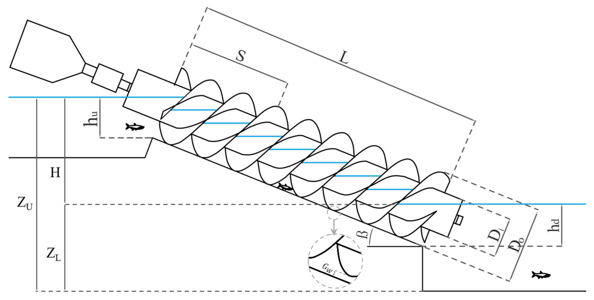
The most important dimensions and parameters required to define the Archimedes screws are represented in Figure 2 and described in Table 1. Archimedes screw design parameters can be categorized as external (DO, L, and β) and internal (Di, N, and S) parameters. Generally, the screw installation site location properties and the passing volumetric flow rate determine the external parameters and the screw performance can then be optimized by adjusting the internal parameters [39].
The installation level (position) of the screw(s) relative to the dam crest or expected level of poundage (reservoir) should be defined considering the determined geometry and optimum inlet level of the Archimedes screw(s). For Archimedes screw generators, it can be shown that the head (H) is the difference of free surface elevations upstream (ZU) and downstream (ZL) of the screw relative to the same datum () [33]. Therefore, the screw length (L) will be:
The inclination angle of the Archimedes screw ( may be limited by the geometry or slope of the installation site. However, Lashofer et al. [10] confirmed that many current industrial ASGs are installed at [10]. Inclination angles less than about 20° increase the length of screw and more than 30° lead to or considerably decrease the capacity of the screw [6].
Increasing the inclination angle also leads to a faster occurrence of the overflow leakage and increasing gap leakage. These issues could be managed by increasing the number of blades [41]. Based on CFD simulations in conjunction with laboratory-scale experiments, Dellinger et al. proposed that for their particular setup, the optimal inclination angle for is about . The maximum efficiency of the four- and five-bladed screws occur in inclination angles between and and the highest power was achieved for , although it was only marginally higher than [41]. However, due to the thickness of the blades, more blades come at the cost of reducing the bucket sizes as well as increasing manufacturing costs and challenges. Modern ASGs usually utilize three or four helical blades (N = 3 or 4). A survey of operating ASG power plants in the UK found that was the most common configuration [42]. Lashofer (2012) observations indicate that for most of Archimedes screw installations [10]. Based on Lyons (2014) experimental observations, there is a considerable reduction in ASGs’ performance for [43]. Rosly et al. (2016) based on CFD simulations of non-rotating screws reported that the number of helix turns (lower is better) are more important than the number of blades so that, the screws with three helix-turns and showed the highest efficiency [44]. Lyons (2014) and Songin (2017) reported that experimental observations showed no significant increase in the Archimedes screw generators’ efficiency for [43,45]. Based on these observations, Dragomirescu (2021) concluded N = 3 as the optimal number of blades [32].
2.2. Archimedes Screws Configurations in Hydropower Plants
It is most common to have only one Archemidian screw installed in a power plant. However, two or more Archimedes screws can be installed in series or parallel to deal with technical limitations, increase the overall energy generation, easier maintenance, or more flexible operation plans. Multiple screws can be configured in series or parallel.
2.2.1. Archimedes Screws in Series Configuration
The idea of installing Archimedes screw pumps (ASPs) in series to pump the fluids into higher levels has been used in practice for a long time (e.g., [46] p. 18). However, installing ASGs in series to take advantage of low flow rate but high heads is not very usual. For higher heads, it is most common to utilize other hydropower technologies, often in combination with a long penstock. However, most hydropower turbines cannot safely pass sediment or larger objects such as living organisms, especially fish. Therefore, one can see Archimedes screws as long as 30 m [27] that are currently installed and in operation (Table 2). However, technical limitations such as bending of long shafts, weight limits of bearings, etc., can limit the maximum length of Archimedes screws. For example, for the two 19 m-long Archimedes screws in the Low Wood project, there is a significant engineering challenge supporting the considerable length and weight of the screw (40 tons) just with bearings at two contact points, one at the top and one at the bottom of the screw [47]. To deal with such limitations, theoretically, several ASGs could be installed in series instead of a very long screw, potentially as a chain of hydropower plants alongside a river or channel [6]. Such a configuration allows utilization of Archimedes screws at locations with an available high head when the available volume of flow rate is low.
2.2.2. Archimedes Screws in Parallel Configuration
The parallel installation of ASGs is the most common configuration in multi-ASG hydropower plants, especially where the volume of flow in a river is so high that a large ASG is required to make use of that amount of water or when the fluctuations in river volumetric of flow rate are considerable. Using several screws in parallel could lead to preventing the technical limitations of a large screw and offers easier maintenance, as well as more flexible operation plans besides taking advantage of a wider range of flow rates that could lead to an increase in the overall energy generation.
2.3. Case Studies
Analysis of current ASG power plants could help in finding common patterns, governing rules and important design points to make guidelines. Table 2 details current hydro power plants using more than one Archimedes screw installed in parallel.
2.4. Evaluation Criteria
In this study, to compare and evaluate the developed equations’ results (i.e., estimations) with the case studies represented in Table 2 (i.e., observations), a combination of visualizations and statistical tests were conducted. Correlations were evaluated by Pearson correlation (R), and the relative differences were calculated by the percentage error (PE) and mean absolute percentage error (MAPE). In the following equations, is the observed value, is the estimated value, is the average of the observed data, is the average of the estimations, and n is the number of data points in the dataset [40].
In statistics, correlation refers to any statistically significant relationship between two variables. The Pearson correlation coefficient measures the linear relationship between two random variables [60] and describes it in a range between −1 to +1. Values close to +1 indicate a good and direct correlation, while values closer to −1 refer to a good but inverse relation between datasets. Values near zero indicate a lack of correlation [61]. These ranges could be represented in percent by multiplying the Pearson correlation to 100. The Pearson correlation is defined as [62].
The percentage (percent) error (PE) is a dimensionless error measure defined as the difference between the model estimations and the experimentally measured value:
The mean absolute percentage error (MAPE) is the average of absolute percentage errors and one of the most common accuracy measures [63] that is recommended in many textbooks (e.g., [64,65]). MAPE considers errors regardless of their sign, so positive and negative errors cannot cancel each other. MAPE is calculated as:
3. Results and Discussion
3.1. Volumetric Flow Rate and Diameter of Archimedes Screws
According to Table 2, current multi-ASG hydropower plants were identified that are designed for the minimum, maximum, and average total flow rates of 4, 28.3 and 14.5 (m3/s), respectively, for a wide range of hydraulic heads between 1.4 m to 10 m. Also, the minimum, maximum and average diameter of installed Archimedes screws in these plants ranges from 2.3 m to 5 m, with an average of about 3.58 m. This is a wide range of diameters per cubic meter of flow rate (between 0.3 m/m3/s to 1.4 m/m3/s and 0.71 m/m3/s on average). Studies showed that in addition to the screw diameter, the inlet depth and rotation speed are also important factors in the volumetric flow rate of ASGs [40].
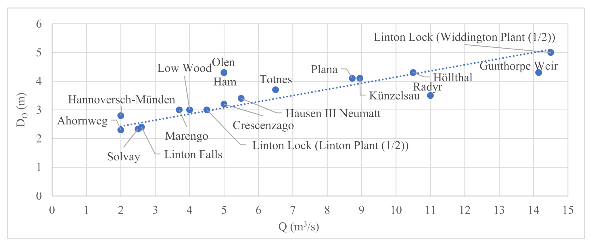
Figure 3 compares the volumetric flow rate and diameter of installed screws in hydropower plants listed in Table 2. The same size screws are installed in all these hydropower plants except at Linton Lock, where the two screws are different sizes. It is worth mentioning that, as discussed, ASGs could be used to upgrade or retrofit the current developments. The Linton Lock power plant is an example of a second ASG installed later as an upgrade.
According to Figure 3, many multi-ASG designs follow a relatively similar trend. For the current multi-ASG hydropower designs, the relationship between the flow rate (Q) and diameter of the screw (DO) can be described linearly as follows. In this relationship, the coefficients are optimized using genetic algorithm optimization:
where DO must be in meters, and Q must be in m3/s. This equation relates the Archimedes screw outer diameter (DO) and passing volumetric flow rate (Q) with reasonable accuracy (, ).
3.2. Power and Diameter of Archimedes Screws
The available hydraulic power could be calculated by the following equation:
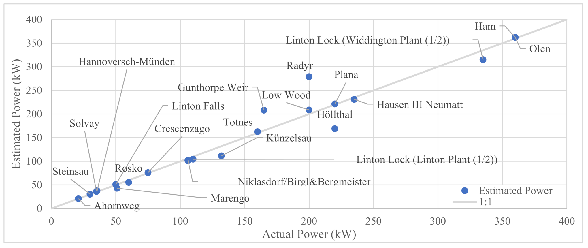
Figure 4 compares the potential available hydraulic power that is calculated using equations with the power that manufacturers estimated that their Archimedes screw designs could generate (Table 2). In this figure, all values are for a single screw, which are determined by dividing plant power by the number of screws, except at Linton Lock, where the two screws are different sizes.
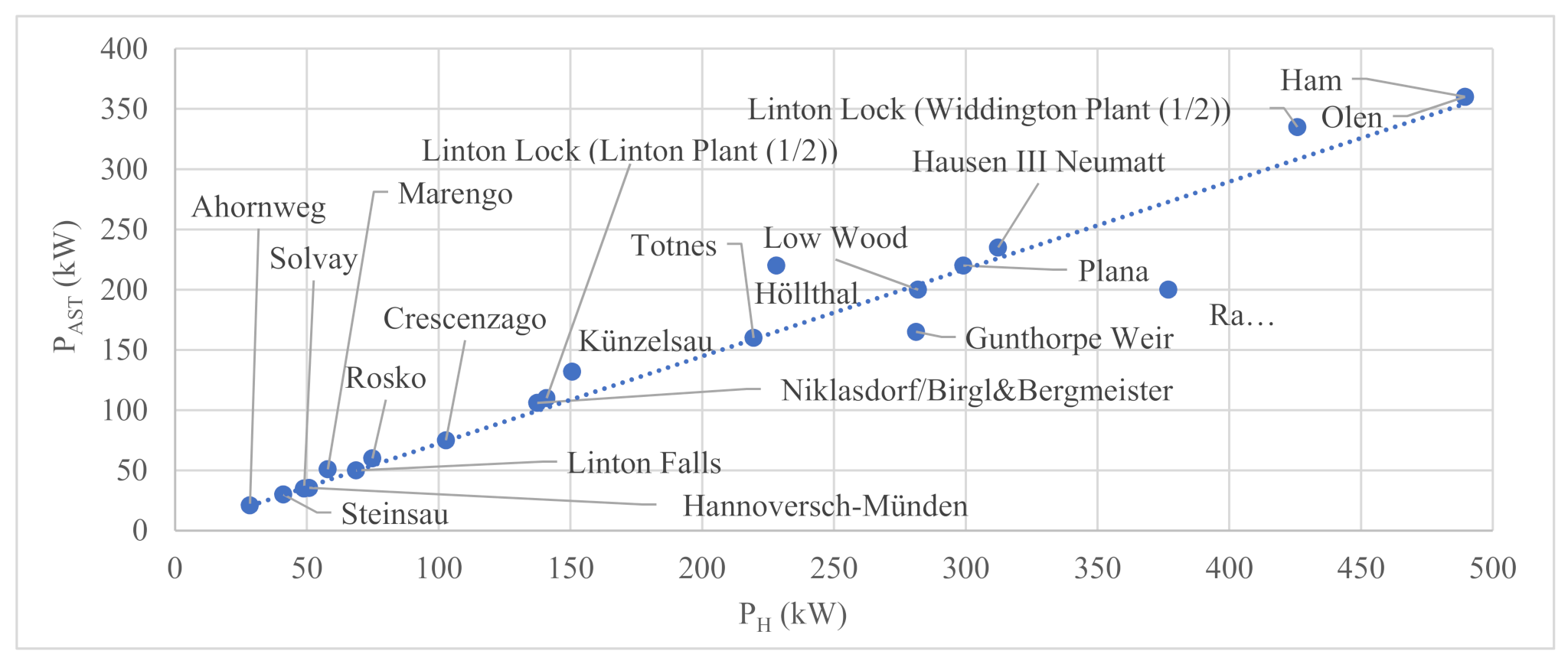
The efficiency of ASGs depends on many variables, including but not limited to the screw’s design, installation, operation condition, fill height, rotation speed, etc. [6]. Typically, ASG water-to-wire efficiency is reported between 60% to 80% [66]. However, some studies reported hydraulic efficiencies of more than 80% in full-load and as high as 94% in partial-load situations [28]. Nonetheless, with reference to Figure 4, many of the studied designs follow a relatively similar trend that could be described as:
where is the specific weight of water and H is the available hydraulic head. Using the generalized reduced gradient (GRG) algorithm [67,68] and the represented case studies in Table 2 to optimize the as a coefficient indicates that for the Equation (7) results are in good agreement with the case studies (R = 97.78%, MAPE = 7.90%). Since the available hydraulic power at a site is the product of head and flow (Equation), the coefficient in Equation (7) suggests that the average efficiency of the plants based on the manufacturer’s specifications in Table 2 is 73.6%, which is consistent with expectations from the literature. These results of estimated power by Equation (7) in comparison with the reported power by the manufacture that also visualized in Figure 5. In this figure, all estimated values are computed for a single screw, and the actual power is determined by dividing plant power by the number of screws except at Linton Lock, where the two screws are in different sizes.
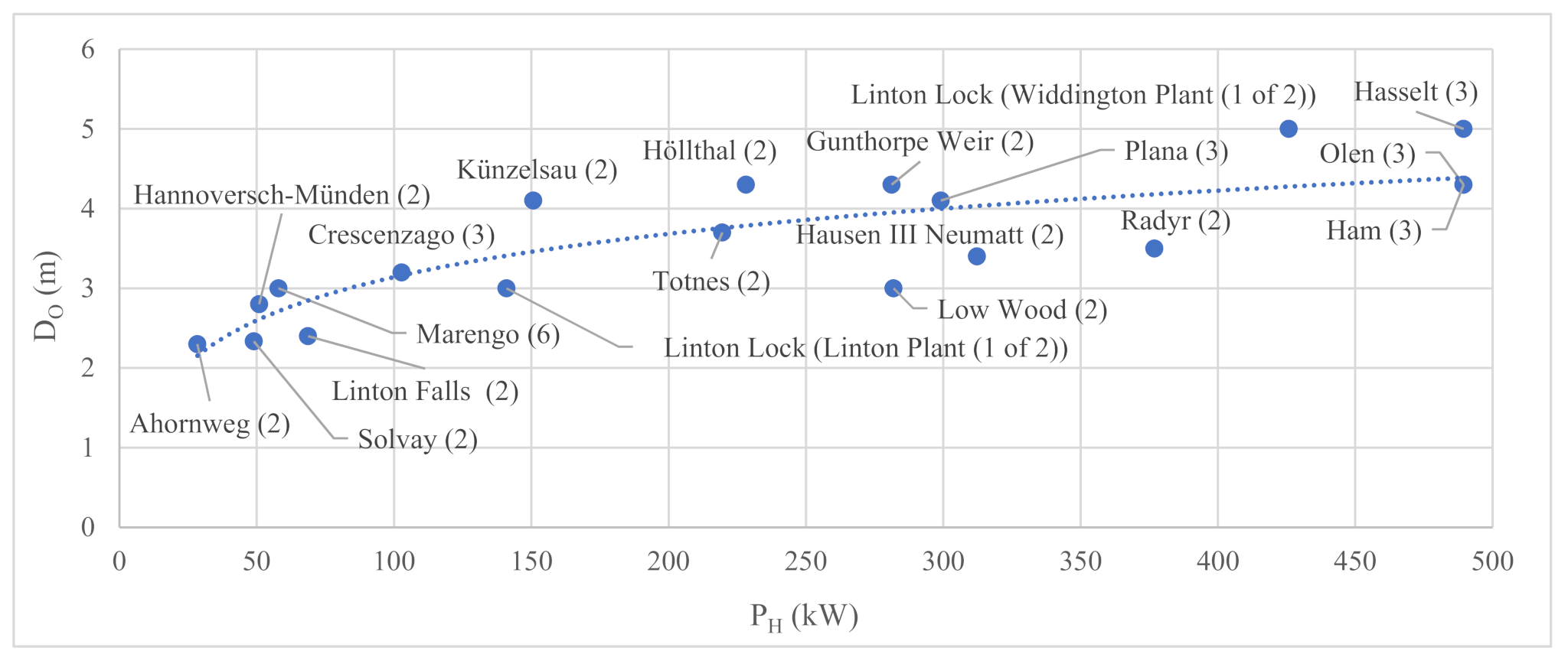
Figure 6 compares the theoretical available hydraulic power (PH) and the diameter of the Archimedes screw designs represented in Table 2. Since the size of screws is the same in almost all power plants, each point represents an ASG hydropower plant, and the number of installed screws is represented in the parentheses in front of each power plant. The only exception is for Linton Lock, where the size of two installed screws is different. Therefore, these screws are distinguished by marking them as (1 of 2).
According to Figure 6, the relationship between the available power and diameter of these Archimedes screws could be defined in the form:
By using the genetic algorithm (GA) and Table 2 to optimize the constants and results in values of and providing reasonable accuracy for these cases (, and ).
3.3. Analytical Equation
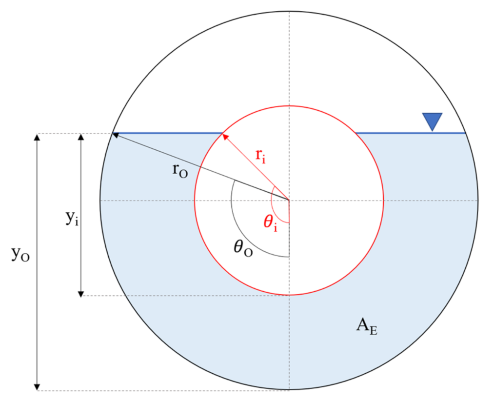
YoosefDoost and Lubitz (2021) developed a concept to define the maximum available area of the screw entrance for any inlet water level, which was called the effective area (AE) [40]. The required parameters to define AE are represented in Figure 7. Using the concept of effective inlet cross-section area [40], YoosefDoost and Lubitz (2021) offered an analytical equation to estimate the overall (outer) diameter of the screw (DO) based on the volumetric flow rate (Q) for the desired rotation speed (ω) [33]:
The simplicity, efficiency and lower cost per watt of single-speed screws make them advantageous in a steady flow [6]. Single-speed Archimedes screws can operate in a partially full condition even if the flow rate is not sufficient to fill the screw at its operation speed [31]. The variable-speed screws are recommended to increase the power generation when the flow varies, as well as if hydropower is the sole source of electricity or for off-grid power plants [6]. Lashofer et al. studies [10] showed that many current industrial ASGs are designed with a rotation speed close to the maximum rotation speed recommended by Muysken () [69]:
Therefore, for full-scale Archimedes screws running at a fixed rotation speed near , Equation (9) could be simplified as:
3.4. Evaluation of the Developed Equations
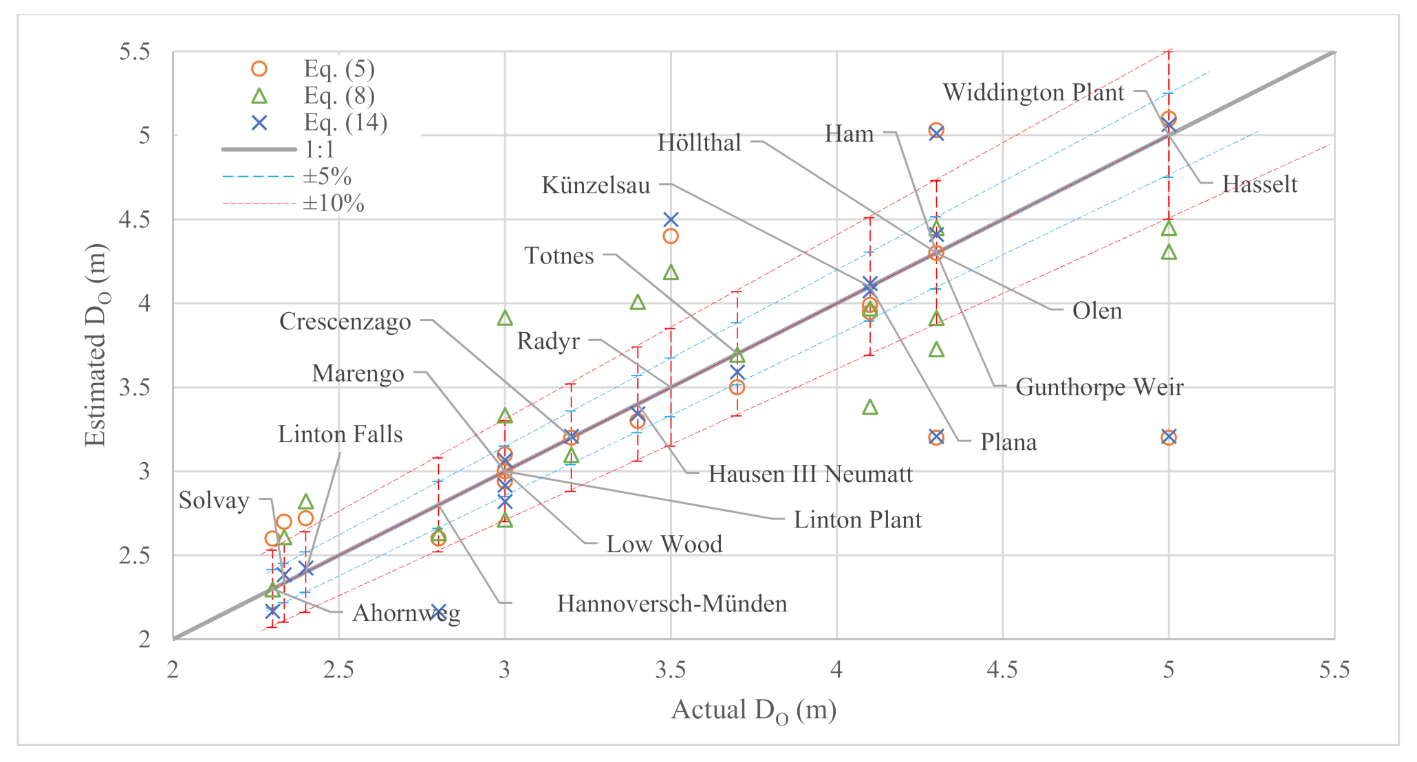
Equations (8) and (14) could be represented in a simplified form by applying the represented values of and constants in Equation (8) and in the analytical Equation (14). The simplified version of the developed empirical Equations (5) and (8), as well as the analytical Equation (14), besides the evaluation results for Archimedes screws based on the evaluation criteria, are summarized in Table 3. Results of each equation for these cases are also visualized in Figure 9.
According to Table 3, Considering the small number of variables required for these equations, all of them indicate arguably reasonable results. The empirical Equation (8) shows the highest correlation with the case studies. Although both empirical Equations (5) and (8) are optimized for the case studies, analytical Equation (14) shows the highest agreement with the current ASG installations in terms of the relative difference. Moreover, the analytical Equation (14)’s strong theoretical basis makes it presumably more reliable and also general.
According to Table 3, Equation (14) estimations have the lowest relative difference with the case studies represented in Table 2. In addition, Figure 9 indicates many of these estimations are in the range of ±5% of the relative difference. However, in several cases, the estimations fall beyond ±10% of the relative difference: according to this figure, the relative difference of Equation (14)’s estimation for Hannoversch Münden multi-ASG hydropower plant seems considerable. More investigations indicate that this ASG has a unique flood protection design that enables it to have a 0° to 28° adjustable inclination angle to operate under variable tailwater levels. Therefore, it is probable that the published data for this ASG is not under a conventional operation condition [33,49]. For the Radyr, the manufacturer published details are roughly [50]. For Gunthorpe Weir Hydro Scheme, Q95 is reported as 28.33, which is according to the published data used in Table 2. However, reviewing the Fisheries and Geomorphology Assessment documents indicates that each screw is designed for 10 m3/s [53]. Using this flow rate and Equation (7) results in much less relative difference for this power plant (PE = 0.44%).
The unique design could be considered as one of the important reasons for the high relative differences between Equation (14) estimations for the Ham and Olen hydropower plants. These screws are installed on the Albert Channel in Ham and Olen in Belgium. These screw designs are unique not only because of their length (21.6 m) but also because they are compact, switchable Archimedes screws. These screws have a unique design to operate as ASPs (780 kW pumping operation) and ASGs (360 kW power generating operation) [56].
The highest relative difference of Equation (14) estimations is for the longest hybrid Archimedean screws in the world, installed on the Albert Canal in the Hasselt hydropower plant. With the remarkable length of 30 m, these ASGs have the most unique designs in the case studies. A hydraulically operated jacket valve is used to switch from pump and turbine mode. In ASP mode, each of these hybrid Archimedes screws can pump 5 m3/s over a head of more than 11 m (installed power 800 MW) during dry seasons and drain 5 m3/s over a head of 10 m to generate 400 MW of energy in wet seasons [27].
4. A Quick Design Guideline for Archimedes Screw Power Plants
In developing hydropower plants, the site and connection assessment expenses, geotechnical, electrical, and civil engineering costs, as well as licensing or approval fees, are among the fixed or semi-fixed soft costs. Many of these activities are carried out just as larger projects. Therefore, regardless of the amount of power that could be generated, these costs are almost the same and so become disproportionate for small projects. For example, these costs are almost the same for 7.2 kW and 150 kW ASG hydropower power plants [70]. However, there are situations that some or several costs could be reduced, at least for initial investigations. For example, when a small dam or weir exists (i.e., upgrade retrofit). Moreover, the results of the analysis of the current multi-ASG hydropower plants help to make some rough estimations. Here are some guidelines for rough estimations of Archimedes screw hydropower plants:
4.1. Determination of the ASG Configuration
- -
- For the known available average flow rate and head, Equation (7) could be used for rough estimations about the possible amount of power that could be generated.
- -
- If the estimated power is less than the requirements, site properties could be checked to evaluate the possibilities of the series configuration of ASGs. e.g., to take advantage of low flow rates but reasonable available heads, ASGs could be installed in series to deal with technical considerations of a very long ASG.
- -
- To take advantage of high flow rates, instead of a very large (in diameter) and heavy ASG, it is possible to install ASGs in parallel. This approach could help to reduce the challenges of technical limitations and offers several advantages.
- -
- For very low flow rates and heads, using industrial pico-ASGs available in the market may facilitate the process or even save some costs. For example, currently, pico-ASGs can generate up to 500 W with a flow rate as low as 0.1 m3/s and 0.7 m of the head (more information is available in [6]). Obviously, several units of such screws could be used in parallel or in series to take advantage of higher flow rates or available heads. For higher flow rates and heads, custom ASGs designs could be more efficient options. For example, Fletcher’s Horse World Archimedes Screw can generate up to 7.2 kW using a design flow rate, head and outer diameter of 0.536 m3/s, 1.7 m [71,72] and 1.39 m [73], respectively.
4.2. Estimation of Archimedes Screws Design Properties
- Determine the site properties: the river’s historical data or hydrograph for the volumetric flow rate (Q) and the site geometry to find the appropriate head (H) and the Archimedes screw inclination angle (. Studies show that many ASGs are installed at [10].
- Determine the maximum and minimum overall diameter of the screw (Dmax, Dmin) based on the site properties and the Archimedes screw hydro power plants design assessments proposed in Section 5-1 of [6].
- Use Equation (1) to determine the screw(s) length.
- Use the historical dataset of the river’s flow rate to determine the flow duration curve (FDC). The probability that a system will take on a particular value or collection of values could be described by a mathematical expression which is known as a distribution function. The cumulative distribution function (CDF) of a variable for a value is the probability that this variable will take values less than or equal to this value [74]. Therefore, for a time series with items, for item with items equal or bigger than it:
In an FDC, the horizontal axis represents the percentage of the period that the flow rate is more than or equal to its corresponding flow rate represented in the vertical axis. Usually, the flow exceeding for 95% of the period () is considered as minimum river flow rate. It is important to note that considering the regulations, hydropower plants may need to bypass a portion of flow for aesthetic, ecological, environmental, or other purposes. This flow is called reserved, residual, compensation, prescribed or hands-off flow and should be deducted from the available flow rates.
- 5.
- Use the volume of flow rate that is provided on the flow duration curve (e.g., Q95) and use Equation (14) to estimate the corresponding diameter of the screw for this flow rate (DO).
- 6.
- Check the estimated diameter:
- -
- If , go to step 7.
- -
- If use a higher volume of flow rate (e.g., Q90) and repeat step 6.
- -
- If , several approaches could be considered:
- ○
- Identical screws: divide the volume of flow rate by i = 2 and follow the process from step 6. If it ends to again, repeat it for i = i + 1 until the condition passes. Then use the analytical Archimedes screw design method that is offered in [33] to design the screw. In this approach, “i” Archimedes screw generators with the same geometry will be designed to handle this flow rate. The advantage of this approach is that similar screws are easier to build, operate and maintain.
- ○
- Design based on the maximum diameter: design the screw for and use the analytical Archimedes screw design method that is offered in [33] to design the Archimedes screw generator. Then use Equation (15) to estimate the volumetric flow that passes through this screw and design the next Archimedes screw by following the process from step 6 for the remaining volume of flow rate. This approach could lead to reducing the number of Archimedes screws.
- ○
- Trial and error: consider a higher probability that means a lower flow rate (e.g., Q97.5 instead of Q95) and do and follow the process from step 6 and perform a trial and error. This approach could lead to an increase in the design of Archimedes screw turbines with higher reliability in generating power.
- 7.
- To utilize the remaining available volumetric flow rate, more Archimedes screws could be designed (parallel ASG power plants). The next flow rate to design the screw could be selected from the FDC based on the desired step size (Δ). For example, for the previous design flow rate of choose the next flow rate which is the flow exceeding for of the period and continue the design starting from step 5.
- 8.
- The design process should be halted based on logical constraints. For example, for economic reasons designing screws for volumetric flow rates less than the certain probability (e.g., Qlimit) is not reasonable. Or, due to site limitations, there may be some restrictions such as the total area of the power plant (the minimum required area to install the Archimedes screw generators is equal to the sum of the diameter times to the length of each screw. If it goes beyond the installation site limitations, some of the screws designed for flow rates with lower probabilities could be cancelled. In such conditions, an optimized larger screw for the flow rates with the highest probabilities or using variable speed screws could be considered as alternative solutions to utilize more flow rate).
- 9.
- Use Equation (7) to estimate the possible amount of power that each ASG can generate. Then, estimate the ideal overall power that the Archimedes screw hydropower plant could generate.
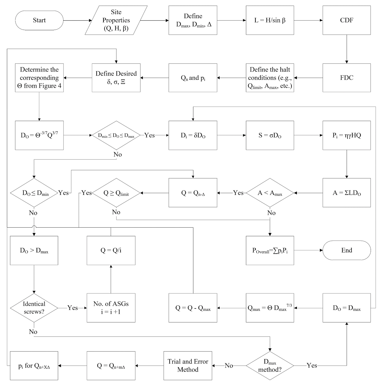
Figure 10 summarizes this guideline as a flow chart.
5. Conclusions
This study focuses on offering a simple method to address the important lack of a general and easy-to-use guideline for designing Archimedes screw power plants using more than one ASG. Then, a detailed design study should be undertaken on the ASGs suggested by this process’s estimations. In addition, this study helps to address one of the significant burdens of small projects, the unscalable initial investigation costs.
Moreover, this study updates the records of the currently installed Archimedes screw generators and provides a better understanding of the advancements and the current possibilities in this technology. It also provides a list of currently installed and operating industrial multi-Archimedes screw hydropower plants in order to review and explore the common design properties between different manufacturers. Therefore, several empirical equations are proposed and optimized using the genetic algorithm and generalized reduced gradient. Moreover, this study provides an updated version of a new analytical method for designing Archimedes screws and offers a new graph that not only supports standard designs but also accelerates and simplifies custom designs. The evaluation of these equations with the list of industrial ASG installations provided indicates they have reasonable accuracy.
The proposed method enables everyone to evaluate the possibilities of green and renewable Archimedes screw hydropower generation where a flow is available and helps to make many potential sites feasible to study for this.
Author Contributions
Conceptualization, A.Y. and W.D.L.; methodology, A.Y. and W.D.L.; software, A.Y.; validation, A.Y. and W.D.L.; formal analysis, A.Y. and W.D.L.; investigation, A.Y. and W.D.L.; resources, A.Y.; data curation, A.Y.; writing—original draft preparation, A.Y.; writing—review and editing, A.Y. and W.D.L.; visualization, A.Y.; supervision, W.D.L.; project administration, W.D.L.; funding acquisition, W.D.L. All authors have read and agreed to the published version of the manuscript.
Funding
This work is part of a larger long-term research program that has been financially supported by the Natural Sciences and Engineering Research Council (NSERC) of Canada, Collaborative Research and Development (CRD) program (grant CRDPJ 513923-17) and Greenbug Energy Inc. (Delhi, ON, Canada).
Data Availability Statement
All data used in this study is reported and referenced in this article.
Conflicts of Interest
The authors declare no conflict of interest.
Abbreviations
The following symbols are used in this paper:
| Notation | ||
| Effective cross-sectional area at the screw’s inlet | (m2) | |
| The inner diameter of the Archimedes screw | (m) | |
| The outer diameter of the Archimedes screw | (m) | |
| The estimated value | ||
| The average of the estimations | ||
| Upper (inlet) water level of the screw | (m) | |
| Lower (outlet) water level of the screw | (m) | |
| The available head | (m) | |
| Gap width (The gap between the trough and screw) | (m) | |
| The total length of the screw | (m) | |
| MAPE | The mean absolute percentage error | (%) |
| n | The number of data points in the dataset | |
| Number of helical planed surfaces | (-) | |
| The observed value | ||
| The average of the observed data | ||
| The percentage (percent) error | (%) | |
| Total flow rate passing through the screw | (m3/s) | |
| r | Radius | (m) |
| R | Pearson correlation | (%) |
| Pitch of the screw (Distance along the screw axis for one complete helical plane turn) | (m) | |
| The fill height of the inner diameter of the screw at the inlet | (m) | |
| The fill height of the screw at the inlet | (m) | |
| The free surface elevations at the upstream | (m) | |
| The free surface elevations at the downstream | (m) | |
| The inclination angle of the screw | (rad) | |
| The specific weight of water | (N/m3) | |
| The screw’s pitch to outer diameter ratio ( | (-) | |
| The average efficiency of the ASGs based on manufacturer’s specifications in Table 2 () | ||
| Step size | (%) | |
| A constant accounting for screw geometry and fill level | (m2/3s−1) | |
| θ | Angle of sector | (rad) |
| The constant value in the power function form | ||
| The screw’s inner to outer diameter ratio () | (-) | |
| The dimensionless inlet depth of the screw | (-) | |
| The value of power in the power function form of diameter equation | (-) | |
| ω | The rotation speed of the screw | (rad/s) |
| The maximum rotation speed of the screw (Muysken limit) | (rad/s) | |
| Subscripts | ||
| inner | ||
| minimum | ||
| Maximum | ||
| O | Outer | |
References
- Williamson, S.J.J.; Stark, B.H.H.; Booker, J.D.D. Low head pico hydro turbine selection using a multi-criteria analysis. RENE 2014, 61, 43–50. [Google Scholar] [CrossRef]
- Date, A.; Akbarzadeh, A. Design and cost analysis of low head simple reaction hydro turbine for remote area power supply. Renew. Energy 2009, 34, 409–415. [Google Scholar] [CrossRef]
- Casini, M. Harvesting energy from in-pipe hydro systems at urban and building scale. Int. J. Smart Grid Clean Energy 2015, 4, 316–327. [Google Scholar] [CrossRef] [Green Version]
- IRENA. Renewable Energy Techlogies: Cost Analysis Series, Hydropower; IRENA Innovation and Technology Centrer: Bonn, Germany, 2012; Volume 1. [Google Scholar]
- Suh, S.H.; Kim, K.Y.; Kim, B.H.; Kim, Y.T.; Kim, T.G.; Roh, H.W.; Yoo, Y.I.; Park, N.H.; Park, J.M.; Shin, C.S.; et al. Theory and Applications of Hydraulic Turbines, 1st ed.; Dong Myeong Publishers: Paju, Korea, 2014. [Google Scholar]
- YoosefDoost, A.; Lubitz, W.D. Archimedes screw turbines: A sustainable development solution for green and renewable energy generation-a review of potential and design procedures. Sustainability 2020, 12, 7352. [Google Scholar] [CrossRef]
- Muller, G.; Senior, J. Simplified theory of Archimedean screws. J. Hydraul. Res. 2009, 47, 666–669. [Google Scholar] [CrossRef]
- Simmons, S.; Lubitz, W. Archimedes screw generators for sustainable energy development. In Proceedings of the 2017 IEEE Canada International Humanitarian Technology Conference (IHTC), Toronto, ON, Canada, 21–22 July 2017; pp. 144–148. [Google Scholar] [CrossRef]
- Moerscher, W. Water-power system. U.S. Patent US1434138A, 31 October 1922. [Google Scholar]
- Lashofer, A.; Hawle, W.; Pelikan, B. State of technology and design guidelines for the Archimedes screw turbine. In Proceedings of the Hydro 2012—Innovative Approaches to Global Challenges, Bilbao, Spain, 29–31 October 2012. [Google Scholar]
- Vandezande BVBA. Lock of Hasselt—Hybrid hydropower screw/screw pump. Youtube. 2018. Available online: https://youtu.be/FUlYjkzAIs8 (accessed on 8 August 2021).
- Kibel, P. Fish Monitoring and Live Fish Trials. Archimedes Screw Turbine, River Dart. In Phase 1 Report: Live Fish Trials, Smolts, Leading Edge Assessment, Disorientation Study, Outflow Monitoring; Moretonhampstead: Devon, UK, 2007. [Google Scholar]
- Boys, C.A.; Pflugrath, B.D.; Mueller, M.; Pander, J.; Deng, Z.D.; Geist, J. Physical and hydraulic forces experienced by fish passing through three different low-head hydropower turbines. Mar. Freshw. Res. 2018, 69, 1934–1944. [Google Scholar] [CrossRef]
- McNabb, C.D.; Liston, C.R.; Borthwick, S.M. Passage of Juvenile Chinook Salmon and other Fish Species through Archimedes Lifts and a Hidrostal Pump at Red Bluff, California. Trans. Am. Fish. Soc. 2003, 132, 326–334. [Google Scholar] [CrossRef]
- Kibel, P.; Pike, R.; Coe, T. Archimedes Screw Turbine Fisheries Assessment. In Phase II: Eels and Kelts; Moretonhampstead: Devon, UK, 2008. [Google Scholar]
- Kibel, P.; Pike, R.; Coe, T. The Archimedes Screw Turbine: Assessment of Three Leading Edge Profiles; Fishtek Consulting Ltd.: Moretonhampstead, UK, 2009. [Google Scholar]
- United Kingdom Environment Agency. Hydropower Good Practice Guidelines Screening requirements. J. Hydraul. Res. 2012, 4, 1–16. [Google Scholar]
- Piper, A.T.; Rosewarne, P.J.; Wright, R.M.; Kemp, P.S. The impact of an Archimedes screw hydropower turbine on fish migration in a lowland river. Ecol. Eng. 2018, 118, 31–42. [Google Scholar] [CrossRef]
- Pauwels, I.S.; Baeyens, R.; Toming, G.; Schneider, M.; Buysse, D.; Coeck, J.; Tuhtan, J.A. Multi-species assessment of injury, mortality, and physical conditions during downstream passage through a large archimedes hydrodynamic screw (Albert canal, Belgium). Sustainability 2020, 12, 8722. [Google Scholar] [CrossRef]
- Durrani, A.M.; Mujahid, O.; Uzair, M. Micro Hydro Power Plant using Sewage Water of Hayatabad Peshawar. In Proceedings of the 2019 15th International Conference on Emerging Technologies (ICET), Peshawar, Pakistan, 2–3 December 2019. [Google Scholar]
- Spaans Babcock Ltd. Hydro Power Using Waste Water at Esholt WwTW. 2009. Available online: https://cms.esi.info/Media/documents/54053_1316689157666.pdf (accessed on 29 July 2020).
- Kozyn, A.; Ash, S.; Lubitz, W.D. Assessment of Archimedes Screw Power Generation Potential in Ontario. In Proceedings of the 4th Climate Change Technology Conference, Montreal, QC, Canada, 25–27 May 2015; pp. 1–11. Available online: https://www.cctc2015.ca/TECHNICALPAPERS/1570095585.pdf (accessed on 3 June 2019).
- Shahverdi, K.; Loni, R.; Maestre, J.M.; Najafi, G. CFD numerical simulation of Archimedes screw turbine with power output analysis. Ocean. Eng. 2021, 231, 108718. [Google Scholar] [CrossRef]
- UNIDO. Renewable Energy: Micro Hydraulic Power Unit (Spiral Type Pico-Hydro Unit ‘PicoPica10’, ‘PicoPica500’); United Nations Industrial Development Organization: Tokyo, Japan, 2020; Available online: http://www.unido.or.jp/en/technology_db/5276/ (accessed on 7 July 2020).
- Sumino, M. Ultra-Small Water Power Generator. 14 May 2019. Available online: https://youtu.be/XjEgFlngZ04 (accessed on 23 June 2020).
- Sumino Co. Ltd. Japan. Spiral Hydraulic Power Unit ‘PicoPica’; Ena: Gifu, Japan, 2020; Available online: http://www.unido.or.jp/files/sites/2/PICOPICA_Specification201127.pdf (accessed on 28 July 2021).
- Vandezande Diksmuide. PS/WKC Lock Hasselt. Available online: https://web.archive.org/web/20210405220637/https://www.vandezande.com/en/projects/ps-wkc-lock-hasselt (accessed on 9 August 2021).
- Rorres, C. Archimedes in the 21st Century: Proceedings of a World Conference at the Courant Institute of Mathematical Sciences; Springer: Cham, Switzerland, 2017. [Google Scholar]
- Brada, K.; Radlik, K.-A. Wasserkraftschnecke: Eigenschaften und Verwendung. In Proceedings of the Heat Exchange and Renewable Energy Sources International Symposium, Szczecin, Poland, 17–19 June 1996; pp. 43–52. [Google Scholar]
- OMNR. Potential Waterpower Generation Sites (WPPOTSTE); Ontario Ministry of Natural Resources. 2004. Available online: https://www.ontario.ca/data/potential-waterpower-generation-sites-wppotste (accessed on 10 January 2015).
- Lubitz, W.D.; Lyons, M.; Simmons, S. Performance Model of Archimedes Screw Hydro Turbines with Variable Fill Level. J. Hydraul. Eng. 2014, 140, 04014050. [Google Scholar] [CrossRef]
- Dragomirescu, A. Design considerations for an Archimedean screw hydro turbine. In Proceedings of the IOP Conference Series: Earth and Environmental Science, Bucharest, Romania, 21–24 October 2021; Volume 664, p. 12034. [Google Scholar] [CrossRef]
- Yoosefdoost, A.; Lubitz, W.D. Archimedes Screw Design: An Analytical Model for Rapid Estimation of Archimedes Screw Geometry. Energies 2021, 14, 7812. [Google Scholar] [CrossRef]
- Nuernbergk, D.M.; Rorres, C. Analytical Model for Water Inflow of an Archimedes Screw Used in Hydropower Generation. J. Hydraul. Eng. 2013, 139, 213–220. [Google Scholar] [CrossRef]
- Aigner, D. Current Research in Hydraulic Engineering 1993–2008; Institut für Wasserbau und Technisch Hydromechanik der TU; Association: Dresden, Germany, 2008. [Google Scholar]
- Schmalz, W. Studies on fish migration and control of possible fish loss caused by the hydrodynamic screw and hydropower plant. In Fischo—Kologische und Limnol. Untersuchungsstelle Sudthurign, Rep.; Thüringer Landesanstalt für Umwelt und Geol: Jena, Germany, 2010. [Google Scholar]
- Lashofer, A.; Kaltenberger, F.; Pelikan, B. Does the Archimedean screw turbine stand the test? (Wie gut bewährt sich die Wasserkraftschnecke in der Praxis?). WasserWirtschaft 2011, 101, 76–81. [Google Scholar] [CrossRef]
- Nuernbergk, D.M. Wasserkraftschnecken—Berechnung und Optimaler Entwurf von Archimedischen Schnecken als Wasserkraftmaschine (Hydro-Power Screws—Calculation and Design of Archimedes Screws), 2nd ed.; Verlag Moritz Schäfer: Detmold, Germany, 2020. [Google Scholar]
- Rorres, C. The Turn of the Screw: Optimal Design of an Archimedes Screw. J. Hydraul. Eng. 2000, 126, 72–80. [Google Scholar] [CrossRef] [Green Version]
- YoosefDoost, A.; Lubitz, W.D. Development of an Equation for the Volume of Flow Passing Through an Archimedes Screw Turbine. In Sustaining Tomorrow; Ting, D.S.-K., Vasel-Be-Hagh, A., Eds.; Springer: Cham, Switzerland, 2021; pp. 17–37. [Google Scholar]
- Dellinger, G.; Simmons, S.; Lubitz, W.D.; Garambois, P.A.; Dellinger, N. Effect of slope and number of blades on Archimedes screw generator power output. Renew. Energy 2019, 136, 896–908. [Google Scholar] [CrossRef]
- Simmons, S.C.; Elliott, C.; Ford, M.; Clayton, A.; Lubitz, W.D. Archimedes screw generator powerplant assessment and field measurement campaign. Energy Sustain. Dev. 2021, 65, 144–161. [Google Scholar] [CrossRef]
- Lyons, M. Lab Testing and Modeling of Archimedes Screw Turbines. Master’s Thesis, University of Guelph, Guelph, ON, Canada, 2014. [Google Scholar]
- Rosly, C.Z.; Jamaludin, U.K.; Azahari, N.S.; Mu’tasim, M.A.N.; Oumer, A.N.; Rao, N.T. Parametric study on efficiency of archimedes screw turbine. ARPN J. Eng. Appl. Sci. 2016, 11, 10904–10908. [Google Scholar]
- Songin, K. Experimental Analysis of Archimedes Screw Turbines. Master’s Thesis, University of Guelph, Guelph, Canada, 2017. [Google Scholar]
- Nagel, G. Archimedean Screw Pump Handbook; RITZ-Pumpenfabrik OHG: Schwabisch Gmund, Germany, 1968. [Google Scholar]
- Rose, R. Linton Falls and Low Wood Hydropower Schemes. No. UK Water Projects 2011. River Coast. 2011, pp. 197–202. Available online: https://web.archive.org/web/20190621110557/http://www.waterprojectsonline.com/case_studies/2011/Hydropower_Linton_Fall_2011s.pdf (accessed on 1 November 2021).
- Landustrie Sneek, B.V. Totnes Weir (UK). Landustrie Worldwide Water Technology. 2015. Available online: https://web.archive.org/web/20210803231005/https://www.landustrie.nl/fileadmin/user_upload/Totnes_Times_November_2015.pdf (accessed on 3 August 2021).
- Rehart Power. Hannoversch Münden CS. Available online: https://web.archive.org/web/20211115031954/https://www.rehart-power.de/en/reference-projects/hydropower-screw-type-cs/hannoversch-muenden-cs.html (accessed on 14 November 2021).
- RenewablesFirst. Radyr Weir Hydro Turbines. 2015. Available online: https://web.archive.org/web/20210804003006/https://www.renewablesfirst.co.uk/project-blog/radyr-weir-hydro-scheme/ (accessed on 5 July 2020).
- Ingenieurbüro Lashofer. Hydropower screws in Europe. Google Maps. Available online: Efort.info/AST-Map (accessed on 3 August 2021).
- Vandezande Diksmuide. Hydropower Screws Höllthal. Vandezande. Available online: https://web.archive.org/web/20210809061648/https://www.vandezande.com/en/projects/hydropower-screws-höllthal (accessed on 9 August 2021).
- Gratton, P.; Meadows, T.; Brook, T. Gunthorpe Weir Hydropower Scheme: Fisheries and Geomorphology Assessment; The Mill: Stroud, UK, 2019. [Google Scholar]
- SinFin. Solvay Industrial Plant; SinFin Energy: Gijón, Spain, 2019; Available online: http://www.sinfinenergy.com/en/projects/solvay/ (accessed on 8 July 2020).
- Landustrie. Linton Lock. Landustrie Sneek BV. 2017. Available online: https://web.archive.org/web/20210804020631/https://www.landustrie.nl/en/products/hydropower/projects/linton-lock.html (accessed on 29 July 2020).
- Vandezande BVBA. Vandezande Specialist in Mechanics. Vandezande.com. Zeepziederijstraat, Brugge, Belgium. Available online: https://web.archive.org/web/20210809031945/https://www.vandezande.com/sites/default/files/vandezande-folder2017-engLR04.pdf (accessed on 8 August 2021).
- Melbud, S.A. A Small Hydropower Plant–Rosko. Available online: https://web.archive.org/web/20210804011025/http://www.melbud.pl/language/pl/mala-elektrownia-wodna-rosko/ (accessed on 3 August 2021).
- Fergnani, N. Hydroelectric Plants Energy Efficiency. Hydrosmart Srl. 2020. Available online: https://www.hydrosmart.it/energia-rinnovabile (accessed on 2 August 2020).
- Sto98. Marengo Hydropower Plant-Goito [Centrale Idroelettrica Marengo—Goito]. YouTube. 2015. Available online: https://youtu.be/19px1EKa--4 (accessed on 19 July 2020).
- Rodgers, J.L.; Nicewander, W.A. Thirteen Ways to Look at the Correlation Coefficient. Am. Stat. 1988, 42, 59–66. [Google Scholar] [CrossRef]
- Yoosefdoost, A.; Yoosefdoost, I.; Asghari, H.; Sadeghian, M.S. Comparison of HadCM3, CSIRO Mk3 and GFDL CM2. 1 in Prediction the Climate Change in Taleghan River Basin. Am. J. Civ. Eng. Archit. 2018, 6, 93–100. [Google Scholar] [CrossRef] [Green Version]
- Adler, J.; Parmryd, I. Quantifying colocalization by correlation: The pearson correlation coefficient is superior to the Mander’s overlap coefficient. Cytom. Part A 2010, 77, 733–742. [Google Scholar] [CrossRef]
- Kim, S.; Kim, H. A new metric of absolute percentage error for intermittent demand forecasts. Int. J. Forecast. 2016, 32, 669–679. [Google Scholar] [CrossRef]
- Hanke, J.E.; Wichern, D. Business Forecasting, 9th ed.; Prentice Hall: London, UK, 2009. [Google Scholar]
- Bowerman, B.L.; O’Connell, R.T.; Koehler, A.B. Forecasting, Time Series, and Regression: An Applied Approach, 4th ed.; Thomson Brooks/Cole: Belmont, CA, USA, 2005. [Google Scholar]
- Hawle, W.; Lashofer, A.; Pelikan, B. Lab Testing of the Archimedean Screw. In Proceedings of the Hidroenergia Conference, Wroclaw, Poland, 23–26 May 2012. [Google Scholar]
- Lasdon, L.S.; Waren, A.D.; Jain, A.; Ratner, M. Design and Testing of a Generalized Reduced Gradient Code for Nonlinear Programming. ACM Trans. Math. Softw. 1978, 4, 34–50. [Google Scholar] [CrossRef]
- Waleed, D.; Alrabadi, H. Portfolio optimization using the generalized reduced gradient nonlinear algorithm An application to Amman Stock Exchange. Int. J. Islam. Middle East. Financ. Manag. 2016, 9, 570–582. [Google Scholar] [CrossRef]
- Muysken, J. Calculation of the Effectiveness of the Auger. De Ingenieur 1932, 21, 77–91. [Google Scholar]
- GreenBug Energy. Archimedes Screw Generators. GreenBug Energy. Available online: https://web.archive.org/web/20210128050704/https://greenbugenergy.com/how-we-do-it/archimedes-screw-generators (accessed on 6 August 2021).
- Heron, L. Fletcher’s Horse World—Nanticoke Creek—Archimedes Screw—7.2 kW. Ontario Rivers Alliance. 2014. Available online: https://web.archive.org/web/20210806171348/https://www.ontarioriversalliance.ca/fletchers-horse-world-nanticoke-creek-archimedes-screw-7-2-kw/ (accessed on 6 August 2021).
- GreenBug Energy. Fletchers Horse World; GreenBug Energy Inc.: Delhi, ON, Canada; Available online: https://greenbugenergy.com/projects/fletchers-horse-world (accessed on 6 August 2021).
- Passamonti, A. Investigation of Energy Losses in Laboratory and Full-Scale Archimedes Screw Generators Advisor; Politecnico Di Milano: Milan, Italy, 2017. [Google Scholar]
- Deisenroth, M.P.; Faisal, A.A.; Ong, C.S. Mathematics for Machine Learning; Cambridge University Press: Cambridge, UK, 2020. [Google Scholar]
Figure 1.
Classification of hydropower plants based on the installation capacity.


Figure 3.
Comparison of the volumetric flow rate and diameter of installed screws in hydropower plants listed in Table 2. All values above are for a single screw.
Figure 3.
Comparison of the volumetric flow rate and diameter of installed screws in hydropower plants listed in Table 2. All values above are for a single screw.

Figure 4.
The theoretical available power vs. the power of installed screws published by manufacturers in current Archimedes screws hydropower plants represented in Table 2.
Figure 4.
The theoretical available power vs. the power of installed screws published by manufacturers in current Archimedes screws hydropower plants represented in Table 2.

Figure 5.
Comparison of the estimated power of each screw vs. the power of each installed screws in ASG hydropower plants.
Figure 5.
Comparison of the estimated power of each screw vs. the power of each installed screws in ASG hydropower plants.

Figure 6.
The theoretical available power vs. the diameter and number of installed screws in current hydropower plants represented in Table 2.
Figure 6.
The theoretical available power vs. the diameter and number of installed screws in current hydropower plants represented in Table 2.

Figure 7.
Parameters to define AE.

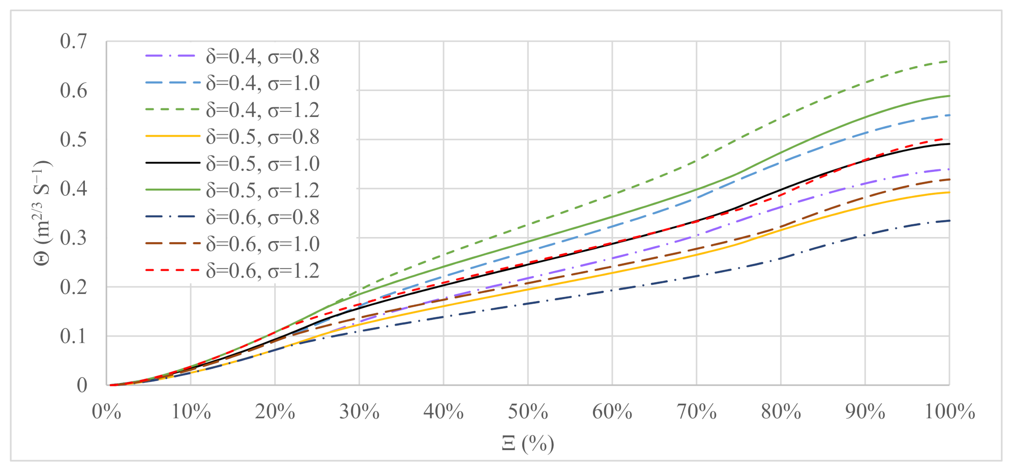
Figure 8.
The corresponding of different and for a full range of Ξ.

Figure 9.
Graphical comparison of Equations (5), (8) and (14) estimations vs. actual overall diameter of ASG installations.
Figure 9.
Graphical comparison of Equations (5), (8) and (14) estimations vs. actual overall diameter of ASG installations.

Figure 10.
The guideline for quick estimations of Archimedes screw power plants design.


Table 1.
Archimedes screws’ geometry and operating variables.
| Parameter | Description | Unit | Variable | Description | Unit |
|---|---|---|---|---|---|
| L | Length of the screw | (m) | ω | Rotation speed of screw * | (rad/s) |
| DO | Outer diameter of the screw | (m) | hu | Upper (inlet) water level | (m) |
| Di | Inner diameter of the screw | (m) | hL | Lower (outlet) water level | (m) |
| S | Screw’s pitch or period [39] (The distance along the screw axis for one complete helical plane turn) | (m) | Q | Volumetric flow rate passing through the screw | (m3/s) |
| N | Number of helical planed surfaces (also called blades, flights or starts [39]) | (1) | Ratio | Description | Unit |
| δ | Inner to outer diameter ratio δ = Di/DO | (1) | |||
| β | Inclination Angle of the Screw | (rad) | σ | Pitch to outer diameter ratio σ = S/DO | (1) |
| Gw | The gap between the trough and screw. | (m) | Ξ | Dimensionless inlet depth Ξ = hu/DO cos β | (1) |
* Note: In the fixed speed Archimedes screws rotation speed is a constant.
Table 2.
Hydropower plants using several parallel Archimedes screw turbines. All screws at a plant are identical unless otherwise noted. Power and flow values are for a single screw at the plant: multiply by the number of screws for total plant flow and power.
Table 2.
Hydropower plants using several parallel Archimedes screw turbines. All screws at a plant are identical unless otherwise noted. Power and flow values are for a single screw at the plant: multiply by the number of screws for total plant flow and power.
| Name | No. of ASGs | DO (m) | H (m) | Q (m3/s) | P (kW) | Location (River) | Refs. | |
|---|---|---|---|---|---|---|---|---|
| Totnes | 2 | 3.7 | 3.45 | 6.5 | 160 | Dart, UK | [48] | |
| Hannoversch-Münden | 2 | 2.8 | 2.6 | 2 | 35.455 | Werra, DE | [49] | |
| Low Wood | 2 | 3 | 7.2 | 4 | 200 | Leven, UK | [47] | |
| Radyr | 2 | 3.5 | 3.5 | 11 | 200 | Taff, UK | [50] | |
| Künzelsau | 2 | 4.1 | 1.72 | 8.95 | 132 | Kocher, DE | [51] | |
| Ahornweg | 2 | 2.3 | 1.45 | 2 | 21 | Mühlbach, DE | [51] | |
| Linton Falls | 2 | 2.4 | 2.7 | 2.6 | 50 | Trent, UK | [47] | |
| Niklasdorf/Birgl and Bergmeister | 2 | 3.9 | 3.6 | 106 | Mur, AT | [51] | ||
| Hausen III Neumatt | 2 | 3.4 | 5.8 | 5.5 | 235 | Wiese, DE | [51] | |
| Höllthal | 2 | 4.3 | 2.22 | 10.5 | 220 | Alz, DE | [52] | |
| Gunthorpe Weir | 2 | 4.3 | 2.03 | 14.15 | 165 | Trent, UK | [53] | |
| Solvay | 2 | 2.3 | 2 | 2.5 | 35 | Saja, ES | [54] | |
| Linton Lock | Linton Plant | 2 | 3 | 3.2 | 4.5 | 110 | Ouse, UK | [6,55] |
| Widdington Plant | 5 | 3 | 14.5 | 335 | ||||
| Plana | 3 | 4.1 | 3.5 | 8.73 | 220 | Vltava, CZ | [51] | |
| Crescenzago | 3 | 3.2 | 2.1 | 5 | 75 | Lambro, IT | [51] | |
| Olen | 3 | 4.3 | 10 | 5 | 360 | Albert Canal, BE | [51,56] | |
| Ham | 3 | 4.3 | 10 | 5 | 360 | Albert Canal, BE | [51,56] | |
| Hasselt | 3 | 5 | 10 | 5 | 400 | Albert Canal, BE | [11,27] | |
| Rosko | 6 | 1.7 | 4.5 | 60 | Noteć, PL | [51,57] | ||
| Steinsau | 6 | 1.4 | 3 | 30 | Ill, FR | [51] | ||
| Marengo | 6 | 3 | 1.6 | 3.7 | 51 | Goito, IT | [58,59] | |
Table 3.
Evaluation of equations based on the evaluation criteria.
| Equation No. | Equation | R (%) | MAPE (%) |
|---|---|---|---|
| (5) | 69.81 | 10.59 | |
| (8) | 83.28 | 10.64 | |
| (14) | 74.38 | 9.69 |
Publisher’s Note: MDPI stays neutral with regard to jurisdictional claims in published maps and institutional affiliations. |
© 2021 by the authors. Licensee MDPI, Basel, Switzerland. This article is an open access article distributed under the terms and conditions of the Creative Commons Attribution (CC BY) license (https://creativecommons.org/licenses/by/4.0/).
Share and Cite
MDPI and ACS Style
YoosefDoost, A.; Lubitz, W.D. Design Guideline for Hydropower Plants Using One or Multiple Archimedes Screws. Processes 2021, 9, 2128. https://doi.org/10.3390/pr9122128
AMA Style
YoosefDoost A, Lubitz WD. Design Guideline for Hydropower Plants Using One or Multiple Archimedes Screws. Processes. 2021; 9(12):2128. https://doi.org/10.3390/pr9122128
Chicago/Turabian StyleYoosefDoost, Arash, and William David Lubitz. 2021. "Design Guideline for Hydropower Plants Using One or Multiple Archimedes Screws" Processes 9, no. 12: 2128. https://doi.org/10.3390/pr9122128
Note that from the first issue of 2016, this journal uses article numbers instead of page numbers. See further details here.