Design and Evaluation of the Lab-Scale Shell and Tube Heat Exchanger (STHE) for Poultry Litter to Energy Production


1
Industrial and Systems Engineering Department, Morgan State University, 1700 East Cold Spring Lane, Baltimore, MD 21251, USA
2
Center for Advanced Energy Systems and Environmental Control Technologies, School of Engineering, Morgan State University, 5200 Perring Parkway, Baltimore, MD 21239, USA
*
Author to whom correspondence should be addressed.
Processes 2020, 8(5), 500; https://doi.org/10.3390/pr8050500
Submission received: 9 April 2020
/
Revised: 22 April 2020
/
Accepted: 24 April 2020
/
Published: 25 April 2020
(This article belongs to the Special Issue Conceptual Design and Energy Analysis in Cycle Gasification Systems and Waste-to-Energy Technologies)
Abstract
:Poultry litter is one type of biomass and waste generated from the farming process. This study performed a performance and process analysis of poultry litter to energy using the lab-scale shell and tube heat exchanger (STHE) system along with a Stirling engine and a swirling fluidized bed combustor (SFBC). The effects of tube shape, flow direction, and water flow rates on water and trailer temperature changes were investigated during the poultry litter co-combustion process. Energy flow analysis and emissions were also studied. Results showed that the water outlet temperature of 62.8 in the twisted tube was higher than the straight tube case (58.3 ) after 130 min of the co-combustion process. It was found that the counter-current direction had higher water temperature changes, higher logarithmic mean temperature difference (LMTD), and higher trailer temperature changes than the co-current direction. A water flow rate of 4.54 L/min showed adequate heat absorption in the lab-scale STHE system and heat rejection in the trailer. Results indicated that the lab-scale STHE system has a conversion efficiency of 42.3% and produces hot water (at about 63.9 ) along with lower emissions. This research study confirmed that poultry litter can be used to generate energy (e.g., hot water and electricity) by using a lab-scale biomass conversion system for space heating applications.

1. Introduction
Fossil fuel depletion and adverse environmental factors (i.e., greenhouse gas emissions causing climate change) play a significant role in seeking alternative renewable energy sources that can replace fossil fuels during energy production processes [1]. Among all the renewable sources, there is an increasing interest in biomass utilization for energy production due to the benefits of the CO2 neutral effect, large availability, and low cost of biomass fuels all over the world [2]. Biomass energy sources are classified into five categories: woody biomass, agricultural biomass, aquatic biomass, animal and human waste, and industrial waste [1,3]. Poultry litter is one type of biomass and animal waste occurring during the poultry farming process. Poultry litter refers to a mixture of poultry manure (excreta), bedding materials (e.g., wood shavings, sawdust, straw, and pine or rice husk), spilled feed, and feathers [4]. In 2009, assuming 1.4 tons of litter per 1000 birds, a total of about 25 million tons of poultry litter was generated by the US and the EU [4]. Poultry growers from the Maryland Eastern Shore region produced over 285 million broilers, resulting in almost 350,000 tons of poultry litter annually [5]. Due to its rich nutrient contents (e.g., N, P, K), most types of poultry litter have traditionally been utilized as a source for organic fertilizer on agricultural land [6]. However, excess land application of poultry litter has led to an overabundance of nutrients (e.g., nitrogen, phosphorus) in the watershed, resulting in eutrophication on water bodies and pollution (e.g., nitrate contamination) particularly along the shores of the Chesapeake Bay, the largest estuary system in the United States [4,7]. This poses a risk to the health and well-being of humans, animals, and the aquatic ecosystem, and therefore, presents an urgent need for efficient and environmentally friendly approaches to dispose of the excess amount of poultry litter [8,9].
According to the farm visit survey from 2017, the annual electricity bill was $15,000 and $36,000 for the Bethel Farms (Salisbury, MD, USA) and Golden Egg Farm (Bishopville, MD, USA), respectively. The cost of heating accounted for a large part of the bill because heating is critical to effectively raise chickens. Pre-heating of a poultry house is important, and it begins at least 24 to 48 h prior to placement of new flocks of baby chicks [10]. The proper maintenance of temperature for the chicken houses during different growth periods is also important for promoting efficient growth. The recommended temperature settings of the broilers are as follows: pre-heating to 31–32 °C two days before baby chickens move into the poultry houses, 30–34 °C for the first seven days, 28–31 °C for days 8–14, 24–27 °C for days 15–21, 21–24 °C for days 22–28, then to 21 °C by the 4th week of development [11]. If the house temperature falls too low, chicks will often huddle and fail to actively seek out feed. Instead, they use the feed to metabolize energy for warmth in place of growth [12]. Over the last several years, there has been increasing interest across the poultry industry in developing different kinds of space heating systems. As shown in Figure 1, three types of space heating systems are most used among the poultry houses: forced air furnace (or box heater), radiant gas heat, and radiant tube heating. Due to the intense heat source in the radiant tube heater near the ceiling, the burners become a serious fire hazard, especially when the tube heater is not installed correctly. The radiant gas heater adds stress to users because workers must raise the heaters before clean-out and a new flock, to allow tractors and equipment to enter the house safely. This process is labor-intensive. Furthermore, forced air furnaces require high energy to heat up the air by convection and are likely the least preferred method for brooding baby chicks [10,12]. Propane and natural gas are currently used as a heating source for major space heating systems among the poultry houses. In addition to the higher energy costs, propane-based space heating systems produce a high concentration of CO2 and moisture as well as room-relative humidity [13]. Increased air moisture and room-relative humidity content (above 70%) can react with poultry litter, resulting in increased ammonia production and potentially negative effects on both bird health and well-being [10,14]. High concentrations of ammonia (above 70 ppm) can reduce growth performance, which results in lower body weight gain and higher feed conversion ratios [14]. In response to elevated fuel prices, poultry health, and excess poultry waste issues, there is overwhelming interest in burning and converting poultry litter into energy which may be used to provide on-farm space heating requirements for poultry houses.
Heat exchangers are used for transferring thermal energy between two or more fluids, or solid particulates and a fluid, at different temperatures and in thermal contact [15]. Different types of heat exchanger are used worldwide that differ from each other because of their specific requirements. Double pipe, shell and tube, plate fin, plate and shell, pillow plate are just a few examples of the types of heat exchangers being used on an industrial scale [16]. The shell and tube heat exchanger (STHE) is one of the most common type of exchanger apparatus widely used in several industries, such as the chemical, petroleum refining, and power generation [16,17]. According to Master et al. [18] and Master et al. [19], more than 30–35% of heat exchangers are the STHE types due to their robust geometry construction, easy maintenance, and possible upgrades. In addition, STHEs are used in different type of industries because they have much lower production cost, are easily cleaned, and considered as more flexible in utility when compared with other heat exchangers. The STHE mainly consists of a shell (vessel with different sizes) and a bundle of tubes inside a shell. In STHE, two fluids of different temperature flow through the heat exchanger without mixing with one another. One working fluid runs through the tubes (the tube side), and the other working fluid flows between the outside tubes and the shell (the shell side). Heat is transferred from one fluid to the other through the tube walls, either from the tube side to the shell side or vice versa to equalize the temperature. The fluids can either be liquids or gases on either the shell or tube side [20]. The type of tube plays an important role in heat transfer enhancement technique, having a great effect on the overall heat transfer process. There are several types of tubes, such as plain, twisted and longitudinally finned, that are available in the current market [20]. Among other types of tubes, twisted tube is a typical passive heat transfer enhancement technique. Twisted tubes can be manufactured from a full range of materials including carbon steels, stainless steels, titanium, copper, and nickel alloys [21]. A summary of typical twisted tubes investigation with various working fluid and tube configurations has been carried out [22]. Qian et al. [23] found that there are various working fluids, such as diesel, air, and water used to test the performance of twisted tubes. However, there has been limited study on investigating the heat transfer performance of the STHE system by using flue gas from the biomass (i.e., poultry litter) combustion process and water as the working fluid. Flue gas from biomass combustion was used to evaluate other types of heat exchangers. Yrjölä and Paavilainen [24] studied the use of heat of flue gas from biomass combustion to heat air in a recuperative heat exchanger and the use of heated air to dry the fuels in a drying silo. Stehlik et al. [25] investigated the performance of a heat exchanger (e.g., air pre-heater, plate heat exchanger, radiation recuperative exchanger) during the biomass combustion process.
The objective of this study was to design, fabricate, and evaluate the lab-scale STHE system during the poultry litter and natural gas co-combustion process. In previous studies, the Stirling engine was integrated into the lab-scale swirling fluidized bed combustor to evaluate electrified outputs and emissions during the poultry litter and natural gas co-combustion process. In this study, the lab-scale STHE system was integrated into the lab-scale swirling fluidized bed combustor (SFBC) and Stirling engine to evaluate performance and analyze the process of converting poultry litter into useful energy (e.g., hot water, electricity).
2. Materials and Methods
2.1. Design Phase of the Lab-Scale Shell and Tube Heat Exchanger
During the design phase, detailed dimensions, numbers and materials for the tubes, baffles, shell, and connections in the lab-scale STHE system were calculated and determined. The lab-scale STHE system consists of tubes, shell, and segmental baffles. There are two types of tubes: straight tube and twisted tube which were used to investigate the effects of tube shape on system performance. Twisted tubes were used to improve the synergy between the velocity and temperature gradient. As a result, the twisted tube was expected to have better heat transfer performance than the straight tube. Segmental baffles were added to not only support the tube bundles, but also to maintain the desired velocity of hot flue gas flow. Moreover, the baffles were used to create turbulence which resists vibrations in order to enhance the fluid and effectively increase the heat transfer coefficient. As shown in Figure 2, a 3D design of tubes with baffle and connections as well as the detailed 2D design of the baffle along with dimensions were completed by using the AutoCAD and ANSYS software. There are six tubes, five segmental baffle and one shell in the lab-scale STHE prototype. The tube (copper tube, Type L Hard Temper ASTM—B88, Cerro Flow Products, Inc., Sauget, IL, USA) has a length of 584.2 mm, inner diameter (ID) of 12.7 mm, and 15.88 mm outer diameter (OD). Segmental baffle (aluminum plate, Model, Company, Country) has a 152.4 mm OD, 3.18 mm thickness, and 92.08 mm height with four holes (15.88 mm ID). The cylinder shell (carbon steel schedule 40, DS Pipe & Steel Supply, LLC., Baltimore, MD, USA) has a length of 685.8 mm, 177.8 mm OD and 152.4 mm ID with two flanges (228.6 mm rectangular plate with 168.28 mm OD center hole and four 12.7 mm OD corner holes, a 381 mm OD circular plate with 168.28 mm OD center hole and four 12.7 mm OD corner holes). Multiple connections (e.g., 12.7 mm 12.7 mm copper 90 sweat sweat Elbow, 12.7 mm Copper Cup Cup Cup Tee Fitting, and 12.7 mm four-way cast copper pipe cross) were selected to connect the tubes. During the design phase, the quantity of pipes was decided by the space between the available market connections while the length of tube was determined by the distance between the combustion chamber and cyclone.
2.2. Fabrication Phase of the Lab-Scale Shell and Tube Heat Exchanger (STHE)
As shown in Figure 3, fabrication of the lab-scale STHE was performed in four steps: (1) raw material selection, (2) cutting, welding, and bending, (3) soldering and assembly, and (4) integration. Raw materials, such as the copper tubes, carbon steel pipe, and aluminum plate, were selected and used to fabricate the tubes, shell, and baffles for the lab-scale STHE prototype in the Center for Advanced Energy Systems and Environmental Control Technologies (CAESECT) at Morgan State University. Cutting machines, 14-gauge swivel head shears (Item 68199, Chicago Electric Power Tools, Calabasas, CA, USA), Bi-metal and hole saw set (Item 68113 68990, WARRIOR, Camarillo, CA, USA), high pressure hydraulic drilling machine, hammer and tube cutter were used to drill holes, and to fabricate segmental baffles and the straight tube. Straight tubes were further twisted and slightly bent to make twisted tubes due to the lack of manufacturing sources in the U.S. that fabricated twisted tubes. Technical staff in the Plumbing Department at Morgan State University assisted in welding the flanges to each side of the cylinder shell. Hard soldering tools, include Berzomatic Map-Pro gas cylinder (14.1 oz) along with a hard soldering kit and 15% Phos-Copper Silver Brazing Alloy rod (12.7 mm 3.18 mm) were acquired to perform hard soldering process at temperature (around 450 ) between tubes and multiple connections of the lab-scale STHE prototype. The surfaces of each pipe and connection were cleaned by a brush. Flux was applied to enhance sealing and to prevent water leakage. Fabricated baffle, copper tube, and other connections were assembled and integrated to complete the lab-scale STHE system prototype.
2.3. Experimental Setup for Process Analysis and Performance Evaluation
Figure 4 illustrates the experimental setup for process analysis and performance evaluation of the lab-scale STHE system during the poultry litter co-combustion process. The lab-scale STHE system was combined with the SFBC chamber, radiators (B-24.64 ECO, eComfort Holdings, Inc., Buffalo Grove, IL, USA), pump, connection pipes, and trailer (2438.4 mm width 6096.0 mm length 2438.4 mm height, Mobile Mini Storage Solutions, Middle River, MD, USA) to simulate the space heating of a poultry house. Natural gas was provided at a height of 120.0 mm for ignition and co-combustion with poultry litter. Poultry litter was fed into the chamber by the biomass feeder. In addition, the primary and secondary blowers along with a voltage regulator were responsible for supplying the combustion air. The 1 kW free piston Stirling engine (E1.4B-00001, Microgen Engine Corporation, Doetinchem, Gelderland, The Netherlands) was inserted into the SFBC system at a height of 406.4 mm to simultaneously generate electricity and heat [7,23]. Hot flue gas from the combustion chamber still carries residual heat and it was supplied into the shell. Then, it was passed through the segmental baffles to heat the water in the lab-scale STHE system. There were a total of five radiators in trailer house to mimic space heating of the poultry house in this study. The processed hot water from the lab-scale STHE system was able to supply the five radiators in series and returned as cold water into the STHE system.
Vortex flow meters (SV4610, Ifm electronic company, Essen, Nordrhein-Westfalen, Germany), K-type thermocouples (Omega TJ36-CASS-18U-6, OMEGA Engineering, Norwalk, CT, USA) along with a data acquisition system (Omega OMB-DAQ-2416, OMEGA Engineering, Norwalk, CT, USA) were carefully installed to monitor water flow rate, water temperature, flue gas, and chamber temperatures. An engine control box, along with a Microgen Test Rig Data Viewer and micro-emission analyzer (Model 500, Enerac, Inc., Holbrook, NY, USA) were used to analyze electricity output and major gaseous emissions (e.g., CO, NOx) after steady-state combustion with an O2 volume between 10% and 12%. Water temperature changes were calculated from the temperature difference between water outlet (hot water) and water inlet (cold water). Trailer temperature was calculated by the real-time average trailer temperatures in three positions: window side, door side, and room side. Hot flue and water were used as the working fluid to investigate the effect of tube shape (straight and twisted), flow direction (co-current and counter-current), water flow rate, and heat input on the lab-scale STHE prototype and space heating performance. The energy flow was analyzed, and the conversion efficiency was calculated while emissions were monitored during the co-combustion process.
Heat transfer of the STHE system can be determined by the measurement of the thermal energy transferred from one point to another and determined by the specific heat, mass, and temperature change. The heat content, Q, is calculated as follows:
where Q = heat content of medium, in Joules; m = mass, in kg; cp = specific heat, in J/g °C; and ΔT = change in temperature, in °C. The specific heat of the flue gas and water were assumed to be 2.01 J/g °C and 4.186 J/g °C, respectively [22]. Heat capture efficiency was calculated by dividing water heat content by flue gas energy content. The logarithmic mean temperature difference (LMTD) was determined from two temperature differences Δt1 and Δt2 at each end of the heat exchanger.
where T1 = shell-side inlet temperature (°C), T2 = shell-side outlet temperature (°C), t1 = tube-side inlet temperature (°C), and t2 = tube-side outlet temperature (°C).
Q = m × cp × ΔT,
3. Results and Discussion
3.1. Effect of Tube Shape: Straight Tube, and Twisted Tube
Figure 5 summarizes the effects of tube shapes (e.g., straight, twisted) on performance (water temperature, trailer temperature) of the lab-scale STHE system. S denotes the straight tube and T denotes the twisted tube in Figure 5. It was observed that CO and NOx emission was increased and SO2 emission was decreased as the mixing ratio of the poultry litter with natural gas increased from 1.89 to 7.42 [7]. Therefore, 7.08 kg/h of poultry litter was fed at the start into the combustion chamber at a mixing ratio of 2.00 to minimize gas emissions during the co-combustion process. The initial water inlet temperature was 17.8 and the water flow rate of 6.81 L/min was kept as constant. It was found that water temperature changes were similar at the beginning 30 min of the co-combustion process. After 135 min of the co-combustion process, the water inlet temperature was increased to 49.4 and the water outlet temperature increased to 62.8 in the twisted tube case. At the same time in the straight tube case, the water inlet temperature was increased to 49.4 and the water outlet temperature increased to 58.3 . It was found that the water temperature change in the twisted tube (13.4 ) was higher than the straight tube (6.9 ). This difference was made more obvious at co-combustion times of 60 min, 75 min, 105 min, and 120 min. In addition, results also indicated that the trailer temperature increased from 23.9 to 38.3 (14.4 increment), 26.1 to 38.9 (12.8 increment) using the twisted and straight tube based STHE system, respectively. In summary, twisted tubes were able to produce a higher water temperature (about 4.5 ), as well as a higher trailer temperature (about 1.6 ), than straight tubes over the course of the co-combustion process. Tan et al. [26,27] also concluded that the heat transfer coefficient for the twisted tube heat exchanger is higher than for other types of heat exchangers. Better heat performance associated with a twisted tube based STHE system was observed because the helical channel formed in the inner tube can be considered as a series of consecutive short sections to change the constant direction and interrupt the steady velocity profile of the water flow. These numerous interruptions can also achieve good transverse mixing and maintain turbulent flow to increase the high convective heat transfer coefficients while achieving better heat transfer performance than laminar flow.
3.2. Effect of Flow Direction: Co-Current and Counter-Current
As shown in Figure 6, the effect of flow direction on the water temperature changes, LMTD, and trailer temperature by using the twisted tube based STHE system were further studied. Co-current refers to the direction of flue gas flow in the shell when equivalent to the direction of water flow. Counter-current refers to the direction of flue gas flow in the shell when opposite to the direction of water flow. In both directions, water temperature changes were sharply increased during the first 90 min and then plateauing at a constant. This is because the total heat input of fuels was kept as 42.20 MJ/h at the beginning and increased to 180.32 MJ/h by addition of poultry litter (PL = 7.08 kg/h) into natural gas (NG = 0.31 10−3 m3/s) in the remaining co-combustion process. It was found that water temperature change in the counter-current is larger than the co-current direction. For instance, counter-flow has the largest water temperature change (33.3 ) with reduction of flue gas temperature (276.6 ) while co-current has water temperature change (20.6 ) with reduction of flue gas temperature (330.4 ). Heat is transferred at a high rate throughout the entire heat exchanger with counter-current direction when compared to co-current direction. This is likely due to the high temperature difference between the cold and hot water. In addition, LMTD of the counter-current flow direction is larger than the co-current flow direction. These results imply that the heat transfer process under counter-current condition is more effective than the co-current condition. Counter-current flow extracted a higher proportion of the heat content from the heating fluid (i.e., hot flue gas) into the cold fluid (i.e., water). The possible reason may be that the hot fluid cools off to some extent but is much warmer than the cold fluid. Thus, cold water entering from right side of the STHE system could absorb heat from the hot flue gas gradually and close to the inlet temperature of hot flue gas when the cold water is moving towards the left side of the STHE system. This process may increase the possibility to achieve a higher water temperature than the co-current case. Moreover, the trailer temperature was increased from 6.1 to 22.8 with an average outside temperature of 1.38 under the counter-current condition. Under a co-current condition, the trailer temperature changed from 8.3 to 24.4 with an average outside temperature of 5.3 . To that end, counter-current direction was observed to have higher water temperature changes, LMTD, and increment of trailer temperature than co-current flow direction.
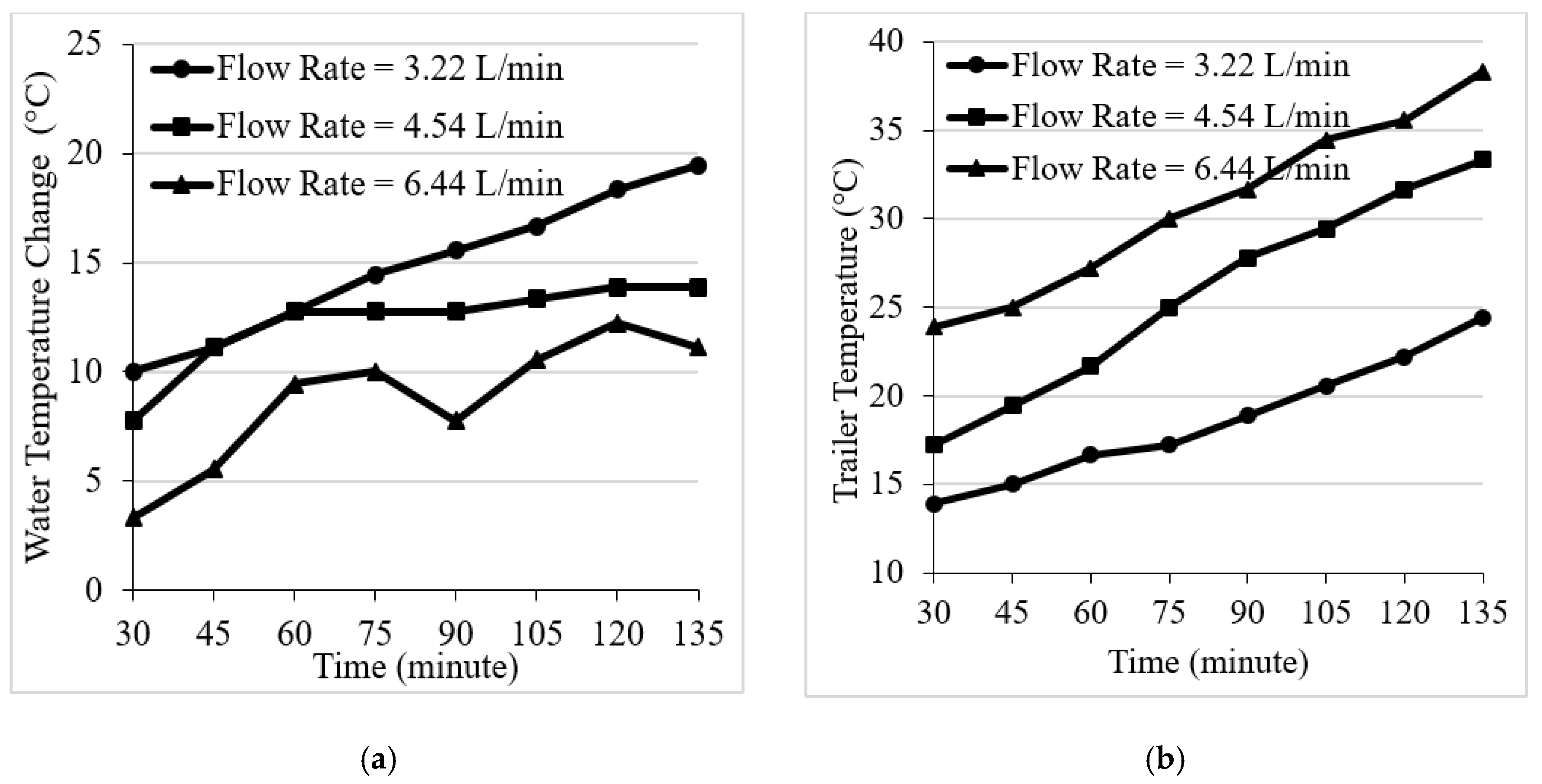
3.3. Effect of Flow Rates: 3.22 L/min, 4.54 L/min, 6.44 L/min
Cold water absorbed heat from the hot flue gas and was converted into hot water in the lab-scale STHE system while hot water ejected heat into the cold air of the trailer house and changed into cold water in the radiators. The flow rates of water are critical in determining the heat transfer rate in both the lab-scale STHE system and radiators in the trailer. This is because the flow rates of water multiplied by a constant specific heat and temperature change determine the heat absorption and rejection rate. Figure 7 summarizes the influence of the water flow rates on the water temperature change and trailer temperature. It was found that temperature changes between the cold water inlet and hot water outlet were in the range of 10.0 to 19.4 , 7.7 to 12.8 , 3.3 to 12.2 on using the lab-scale twisted tube-based STHE at water flow rates of 3.22 L/min, 4.54 L/min, and 6.44 L/min, respectively. Lower flow rates had a larger temperature change between cold water inlet and hot water outlet because there was sufficient time to absorb heat from the hot flue gas into the water medium. However, there is a limitation on the amount of heat rejection associated with a lower water flow rate during the space heating process of the trailer house. Trailer temperatures were observed to have increased to 24.4 , 33.3 and 38.3 at water flow rates of 3.22 L/min, 4.54 L/min, and 6.44 L/min, respectively. The trailer had the highest temperature of 38.3 at a water rate of 6.44 L/min after 135 min of co-combustion. A higher water flow rate (6.44 L/min) had a better heat transfer process in the trailer than lower flow rates because high amounts of heat at higher flow rate were ejected from the hot water in the radiators into the cold air of the trailer. However, the amount of rejected heat in the hot water of the radiators is still lower than the required heat in the cold air of the trailer. Thus, a higher water flow rate is required in the trailer to eject sufficient heat into the cold air and have equilibrium between the hot water and the cold air. The trailer temperature changers were 10.6 , 16.1 and 14.4 water flow rates of 3.22 L/min, 4.54 L/min, 6.44 L/min respectively. Results also indicate that higher water flow rates had higher trailer temperature increments to achieve the equilibrium between the air and water temperature.
3.4. Energy Flow, Conversion Efficiency, and Emissions Analysis
Energy flow analysis is an effective tool to perform an analysis and to propose sustainable systems. As shown in Figure 8, a schematic diagram, the energy production and heat flow during the co-combustion process in the lab-scale biomass conversion system was analyzed.
The higher heating value (HHV) of poultry litter and natural gas was found to be 11.30 MJ/kg and 46.52 MJ/kg, respectively [28]. HHV was multiplied by the mass flow rate to derive the total heating input of poultry litter. Then, HHV of natural gas was multiplied by the volumetric flow rate and density to calculate the total heating input of natural gas. The density of air and natural gas were assumed to be 1.225 kg/m3 and 0.8 kg/m3, respectively. Thereafter, the total mass flow rate of fuel and air were calculated. The specific heats of flue gas (2.01 J/g °C) and water (4.186 J/g °C) were assumed. The flue gas temperature change (681.2 °C) was measured to calculate the heat generated in the flue gas stream (71.14 MJ/h). In the meantime, it was found that the partial heat was used to produce electricity (about 1 kW) with a conversion efficiency of 20%. Thus, the total energy from the combustion process was divided into the flue gas stream (58.3%), Stirling engine (14.7%), and heat loss (27.0%). There was heat loss through conduction and radiation from the combustion chamber surface and bottom ash production. Results indicated that the flue gas was decreased from 681.2 to 389.9 while the water temperature was increased from 44.4 to 58.3 at a flow rate of 4.43 L/min in the STHE system. It was found that the lab-scale STHE system was used to collect 44.3% of the residual heat (15.44 MJ/h) from the flue gas stream (31.49 MJ/h) to produce hot water (about 57.2 °C). The produced hot water was sent to the radiators in the trailer and ultimately transferred heat into the cold air.
In order to evaluate the conversion efficiency of the STHE system, the amount of heat change in the water was divided by the amount of heat change in the flue gas under different operating conditions. Table 1 summarizes the results of the measured system output (e.g., flue gas temperature from biomass combustion, water temperature) and the calculated conversion efficiency at various operating conditions (e.g., flow direction, feeding rate of fuels, and water). Results indicated that the lab-scale STHE system may have produced hot water (about 63.9 ) with higher efficiency (up to 42.3%). Accordingly, the system may have a lower hot water temperature (about 30.6 ) at a lower conversion efficiency (close to 22.8%). It was also found that the counter-current flow with lower water flow rate may have a higher conversion efficiency than the co-current flow with a higher water flow rate because this setting provided enough water transport time and heat absorption time. It was also found that the conversion efficiency was increased by increasing the mixing ratio and higher energy content of poultry litter in the natural gas during the co-combustion process.
Emission standards and regulations vary by country, as well as issue date of license, biomass fuel type, heat output, and reference O2 concentration. As shown in Table 2, the NOx emission from co-combustion in the lab-scale biomass conversion process is significantly lower than the European emission limits. The lower emission of NOx can be explained by the combination effect of the decreased freeboard temperature in reducing the small amount of thermal NOx formation and increased species, such as char and CO in the fuel bed region to form a reducing environment. Therefore, NO can be reduced by the char suspended within the freeboard, i.e., 2NO + 2C → N2 + CO. In addition, NOx reduction appears when a large amount of CO emissions splashed and entrained into the freeboard and interacted with NO emission (2NO + 2CO → 2CO2 + N2) [7,9,23]. It is not surprising, therefore, that the CO emission is a little higher than the emission limits because there are two possible causes of CO increment: (1) added moisture from poultry litter, which may have caused convective cooling in the bed region and inhibited conversion of CO into CO2, and (2) the high volatile content of poultry litter attributed to the cooling effect and remaining unburnt in the upper part of the combustor [4,7,23].
4. Conclusions
Owing to the increasing cost of fuels and environmental problems associated with excess production and land application of poultry litter, it is imperative that poultry litter is converted into useful energy via the lab-scale STHE system. In this study a lab-scale STHE system was designed, fabricated, and evaluated. Effects of tube shape, flow direction, and water flow rates on system performance were investigated. Results showed that the twisted tube had a better performance than the straight tube in terms of higher water temperature changes (about 4.5 ) and trailer temperature increment (about 1.6 ). It was observed that the counter-current flow of the flue gas and the water had higher water temperature changes, LMTD, and trailer temperature increments, compared to co- current flow. In the meantime, water flow rate of 4.54 L/min was preferred because a higher water flow rate reduced the water temperature changes in the STHE system while a lower water flow rate decreased the trailer temperature increment. It is recommended to use the twisted tube at a water flow rate of 4.54 L/min and co-current direction to increase system performance. Energy flow analysis found that the lab-scale STHE system was able to collect 42.3% of residual heat from the flue gas and produce hot water (about 63.9 °C). Emission results indicate that NOx emission is significantly lower and CO emission is slightly higher than the European emission limits. This study showed that it is possible for poultry litter to be a viable source of space heating in order to reduce propane consumption and address run-off issues. It also provided a drier heat to mitigate ammonia concentration in the poultry house. An effective and environmentally friendly modality for space heating from a poultry litter combustion process using lab-scale STHE along with the Stirling engine and SFBC system can save energy costs, protect the environment, and increase the yield of chickens. In future study, the combination effect of water flow rates and flow direction on conversion efficiency of the lab-scale STHE system will be further investigated. In addition, heat transfer analysis and energy production of the SFBC and pilot-scale STHE system will be performed in poultry houses to identify the feasibility of space heating in the field.
Author Contributions
S.W.L. and X.Q. coordinated projects and received grants from the Abell Foundation. X.Q. conducted the literature reviews and found the research gaps. X.Q. and S.W.L. conceived and designed the approach to set up the testing facility and collected results. X.Q. and Y.Y. collected poultry litter samples from a poultry farm and performed the combustion test. X.Q. and S.W.L. collected and analyzed experimental results in this study. X.Q. and S.W.L. wrote the draft manuscript. S.W.L. reviewed this manuscript and provided his constructive comments and suggestions to improve the quality of the article. All authors have read and agreed to the published version of the manuscript.
Funding
This research was funded by the Abell Foundation and the APC was partially funded by the School of Graduate Studies at Morgan State University.
Acknowledgments
The authors would like to acknowledge the Abell Foundation and Office of Technology at Morgan State University for providing sponsorship and financial support to conduct this research. In addition, authors would like to appreciate the kind support of the research staff and facilities from the Center for Advanced Energy Systems and Environmental Control Technologies (CAESECT).
Conflicts of Interest
The authors declare no conflicts of interest.
References
- Patel, M.; Zhang, X.; Kumar, A. Techno-economic and life cycle assessment on lignocellulosic biomass thermochemical conversion technologies: A review. Renew. Sustain. Energy Rev. 2016, 53, 1486–1499. [Google Scholar] [CrossRef]
- Saidur, R.; Abdelaziz, E.A.; Demirbas, A.; Hossain, M.S.; Mekhilef, S. A review on biomass as a fuel for boilers. Renew. Sustain. Energy Rev. 2011, 15, 2262–2289. [Google Scholar] [CrossRef]
- Tripathi, M.; Sahu, J.N.; Ganesan, P. Effect of process parameters on production of biochar from biomass waste through pyrolysis: A review. Renew. Sustain. Energy Rev. 2016, 55, 467–481. [Google Scholar] [CrossRef]
- Lynch, D.; Henihan, A.M.; Bowen, B.; Lynch, D.; McDonnell, K.; Kwapinski, W.; Leahy, J.J. Utilisation of poultry litter as an energy feedstock. Biomass Bioenergy 2013, 49, 197–204. [Google Scholar] [CrossRef] [Green Version]
- Parker, D.; Li, Q. Poultry Litter Use and Transport in Caroline, Queen Anne’s Somerset and Wicomico Counties in Maryland: A Summary Report. Mid-Atlantic Regional Water Program. 2006. Available online: https://p2infohouse.org/ref/41/40131.pdf (accessed on 23 March 2019).
- Kelleher, B.P.; Leahy, J.J.; Henihan, A.M.; O’dwyer, T.F.; Sutton, D.; Leahy, M.J. Advances in poultry litter disposal technology–a review. Bioresour. Technol. 2002, 83, 27–36. [Google Scholar] [CrossRef]
- Qian, X.; Lee, S.; Chandrasekaran, R.; Yang, Y.; Caballes, M.; Alamu, O.; Chen, G. Electricity evaluation and emission characteristics of poultry litter co-combustion process. Appl. Sci. 2019, 9, 4116. [Google Scholar] [CrossRef] [Green Version]
- Abelha, P.; Gulyurtlu, I.; Boavida, D.; Barros, J.S.; Cabrita, I.; Leahy, J.; Kelleher, B.; Leahy, M. Combustion of poultry litter in a fluidised bed combustor. Fuel 2003, 82, 687–692. [Google Scholar] [CrossRef]
- Li, S.; Wu, A.; Deng, S.; Pan, W.P. Effect of co-combustion of chicken litter and coal on emissions in a laboratory-scale fluidized bed combustor. Fuel Process. Technol. 2008, 89, 7–12. [Google Scholar] [CrossRef]
- Cui, Y.; Theo, E.; Gurler, T.; Su, Y.; Saffa, R. A comprehensive review on renewable and sustainable heating systems for poultry farming. Int. J. Low-Carbon Technol. 2020, 15, 121–142. [Google Scholar] [CrossRef]
- Liang, Y.; Tabler, G.T.; Watkins, S.E.; Xin, H.; Berry, I.L. Energy use analysis of open-curtain vs. totally enclosed broiler houses in northwest Arkansas. Appl. Eng. Agric. 2009, 25, 577–584. [Google Scholar] [CrossRef] [Green Version]
- May, J.D.; Lott, B.D. The effect of environmental temperature on growth and feed conversion of broilers to 21 days of age. Poult. Sci. 2000, 79, 669–671. [Google Scholar] [CrossRef] [PubMed]
- Smith, S.; Meade, J.; Gibbons, J.; McGill, K.; Bolton, D.; White, P. Impact of direct and indirect heating systems in broiler units on environmental conditions and flock performance. J. Integr. Agric. 2016, 15, 2588–2595. [Google Scholar] [CrossRef] [Green Version]
- Yi, B.; Chen, L.; Sa, R.; Zhong, R.; Xing, H.; Zhang, H. High concentrations of atmospheric ammonia induce alterations of gene expression in the breast muscle of broilers (Gallus gallus) based on RNA-Seq. BMC Genom. 2016, 17, 598. [Google Scholar] [CrossRef] [PubMed] [Green Version]
- Bichkar, P.; Dandgaval, O.; Dalvi, P.; Godase, R.; Dey, T. Study of shell and tube heat exchanger with the effect of types of baffles. Procedia Manuf. 2018, 20, 195–200. [Google Scholar] [CrossRef]
- Salahuddin, U.; Bilal, M.; Ejaz, H. A review of the advancements made in helical baffles used in shell and tube heat exchangers. Int. Commun. Heat Mass 2015, 67, 104–108. [Google Scholar] [CrossRef]
- Duan, Z.; Shen, F.; Cao, X.; Zhang, J. Comprehensive effects of baffle configuration on the performance of heat exchanger with helical baffles. Nucl. Eng. Des. 2016, 300, 349–357. [Google Scholar] [CrossRef]
- Master, B.I.; Chunangad, K.S.; Pushpanathan, V. Fouling mitigation using helixchanger heat exchangers. In Proceedings of the ECI Conference on Heat Exchanger Fouling and Cleaning: Fundamentals and Applications, Santa Fe, NM, USA, 18–22 May 2003; pp. 17–322. [Google Scholar]
- Master, B.I.; Chunangad, K.S.; Boxma, A.J.; Karl, D.; Stehlik, P. Most frequently used heat exchangers from pioneering research to worldwide applications. Heat Transf. Eng. 2006, 27, 4–11. [Google Scholar] [CrossRef]
- Dubey, V.V.P.; Verma, R.R.; Verma, P.S.; Srivastava, A.K. Performance analysis of shell and tube type heat exchanger under the effect of varied operating condition. IOSR J. Mech. Civ. Eng. 2014, 11, 8–17. [Google Scholar] [CrossRef]
- Danielsen, S.O. Investigation of a Twisted-Tube Type Shell-and-Tube Heat Exchanger. Master’s Thesis, Institutt for Energi-og Prosessteknikk, Trondeim, Norway, June 2009. [Google Scholar]
- Yang, S.; Zhang, L.; Xu, H. Experimental study on convective heat transfer and flow resistance characteristics of water flow in twisted elliptical tubes. Appl. Therm. Eng. 2011, 31, 2981–2991. [Google Scholar] [CrossRef]
- Qian, X. Statistical Analysis and Evaluation of the Advanced Biomass and Natural Gas Co-Combustion Performance. Ph.D. Thesis, Morgan State University, Baltimore, MD, USA, 2019. [Google Scholar]
- Yrjölä, J.; Paavilainen, J. Modelling and analyses of heat exchangers in a biomass boiler plant. Int. J. Energy Res. 2004, 28, 473–494. [Google Scholar] [CrossRef]
- Stehlik, P. Heat exchangers as equipment and integrated items in waste and biomass processing. Heat Transf. Eng. 2007, 28, 383–397. [Google Scholar] [CrossRef]
- Tan, X.H.; Zhu, D.S.; Zhou, G.Y.; Zeng, L.D. Experimental and numerical study of convective heat transfer and fluid flow in twisted oval tubes. Int. J. Heat Mass Transf. 2012, 55, 4701–4710. [Google Scholar] [CrossRef]
- Tan, X.H.; Zhu, D.S.; Zhou, G.Y.; Zeng, L.D. Heat transfer and pressure drop performance of twisted oval tube heat exchanger. Appl. Therm. Eng. 2013, 50, 374–383. [Google Scholar] [CrossRef]
- Qian, X.; Lee, S.; Soto, A.-M.; Chen, G. Regression model to predict the higher heating value of poultry waste from proximate analysis. Resources 2018, 7, 39. [Google Scholar] [CrossRef] [Green Version]
- Koppejan, J.; Van Loo, S. The Handbook of Biomass Combustion and Co-Firing. Reprint; Earthscan: London, UK, 2010; pp. 129–132. [Google Scholar]
Figure 1.
Major space heating systems in the poultry houses: (a) Forced air furnace. (b) Radiant gas heater. (c) Radiant tube heater.
Figure 1.
Major space heating systems in the poultry houses: (a) Forced air furnace. (b) Radiant gas heater. (c) Radiant tube heater.

Figure 2.
Design of the lab-scale shell and tube heat exchanger (STHE) components: (a) 3D model without shell (b) 2D baffle (units: mm).
Figure 2.
Design of the lab-scale shell and tube heat exchanger (STHE) components: (a) 3D model without shell (b) 2D baffle (units: mm).

Figure 3.
Fabrication process of the lab-scale STHE prototype.

Figure 4.
The experimental STHE system setup for process analysis and performance evaluation.

Figure 5.
Comparison performance of the straight tube-based STHE and twisted tube-based STHE.

Figure 6.
Effect of flow direction on water and trailer temperature changes.

Figure 7.
Effect of flow rates on water temperature changes of: (a) STHE, (b) Trailer.

Figure 8.
Energy production and heat flow of poultry litter in the energy conversion process.


Table 1.
Conversion efficiency of STHE system under various operating conditions.
| Flow Direction | Poultry Litter (kg/h)/Natural Gas (m3/h) | Water Flow Rate (L/min) | Gas Temp. () | Water Temp. ( ) | Conversion Efficiency (%) | ||
|---|---|---|---|---|---|---|---|
| Hot | Cold | Cold | Hot | ||||
| Co-current | 2.09/1.13 | 2.40 | 516.2 | 190.9 | 17.8 | 30.6 | 22.8 |
| Co-current | 7.08/1.13 | 2.40 | 537.6 | 255.9 | 26.1 | 42.2 | 30.3 |
| Co-current | 9.71/1.13 | 2.40 | 670.5 | 340.1 | 32.2 | 52.8 | 31.6 |
| Counter-current | 2.09/1.13 | 1.70 | 494.2 | 276.5 | 13.9 | 34.4 | 37.9 |
| Counter-current | 7.08/1.13 | 1.70 | 547.3 | 314.8 | 16.7 | 41.7 | 39.4 |
| Counter-current | 9.71/1.13 | 1.70 | 674.5 | 397.9 | 30.6 | 63.9 | 42.3 |
Table 2.
Summary and comparison of emissions standards and tested results.
| Country | Heat Output (MW) | Fuel Type | CO (ppm) | NOx (ppm) | Ref. |
|---|---|---|---|---|---|
| Germany | 0.1–1.0 | straw (or similar) | 218.3 | 265.8 | [29] |
| Belgium | 0.5–1.0 | clean wood | 218.3 | 265.8 | [29] |
| Norway | 0.5–1.0 | biomass | 140.0 | 132.9 | [29] |
| Emission results of the lab-scale biomass conversion system | |||||
| U. S. | 33.9 kW | poultry litter | 180–350 | 8–35 | N/A |
© 2020 by the authors. Licensee MDPI, Basel, Switzerland. This article is an open access article distributed under the terms and conditions of the Creative Commons Attribution (CC BY) license (http://creativecommons.org/licenses/by/4.0/).
Share and Cite
MDPI and ACS Style
Qian, X.; Yang, Y.; Lee, S.W. Design and Evaluation of the Lab-Scale Shell and Tube Heat Exchanger (STHE) for Poultry Litter to Energy Production. Processes 2020, 8, 500. https://doi.org/10.3390/pr8050500
AMA Style
Qian X, Yang Y, Lee SW. Design and Evaluation of the Lab-Scale Shell and Tube Heat Exchanger (STHE) for Poultry Litter to Energy Production. Processes. 2020; 8(5):500. https://doi.org/10.3390/pr8050500
Chicago/Turabian StyleQian, Xuejun, Yulai Yang, and Seong W. Lee. 2020. "Design and Evaluation of the Lab-Scale Shell and Tube Heat Exchanger (STHE) for Poultry Litter to Energy Production" Processes 8, no. 5: 500. https://doi.org/10.3390/pr8050500
Note that from the first issue of 2016, this journal uses article numbers instead of page numbers. See further details here.