
The Role of Orientation and Temperature on the Mechanical Properties of a 20 Years Old Wind Turbine Blade GFR Composite

 ,
,  , and
, and 
Abstract
:
1. Introduction
2. Materials and Methods
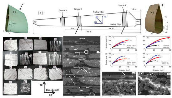
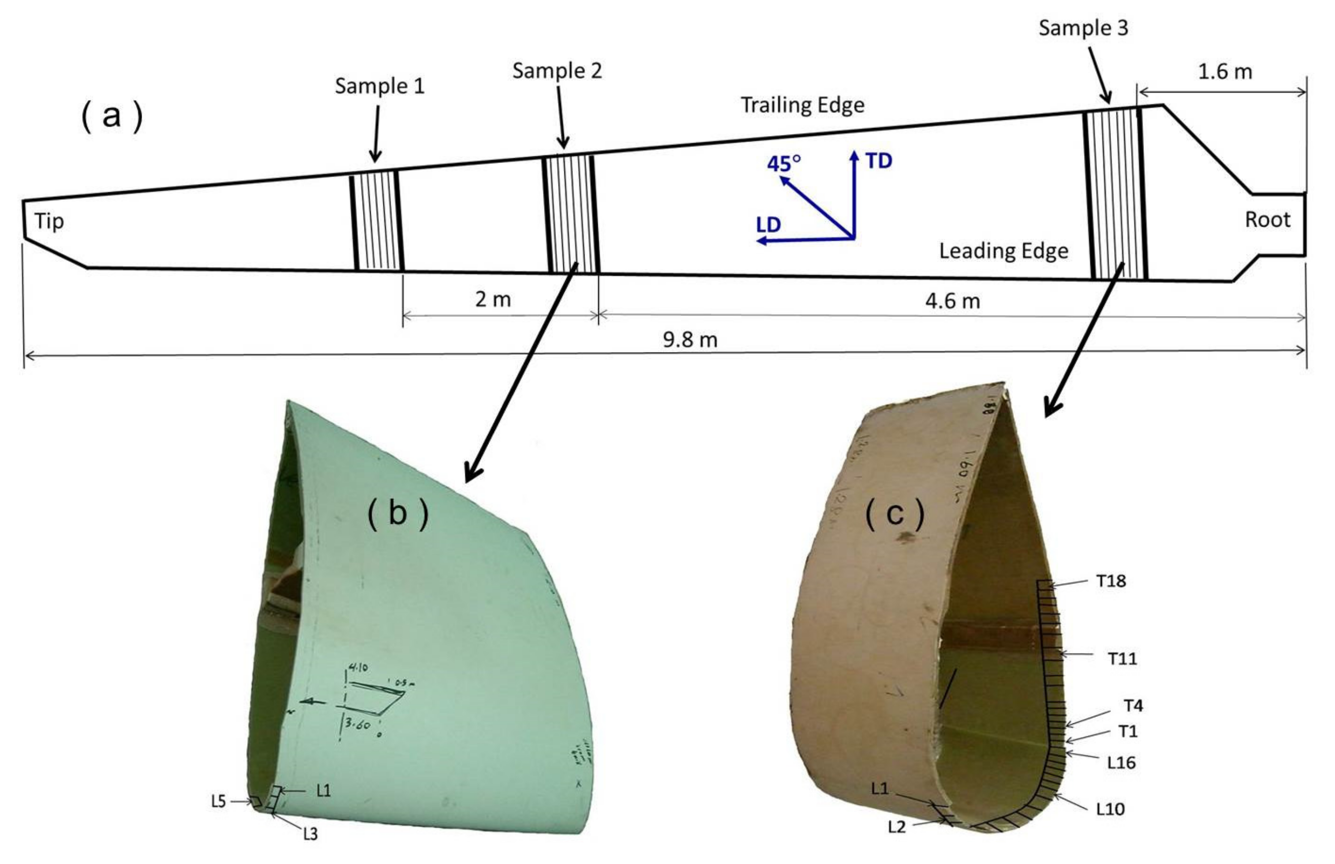
2.1. Material Sampling
2.2. Characterization Method
2.2.1. Lay-Up Sequence and Microstructure
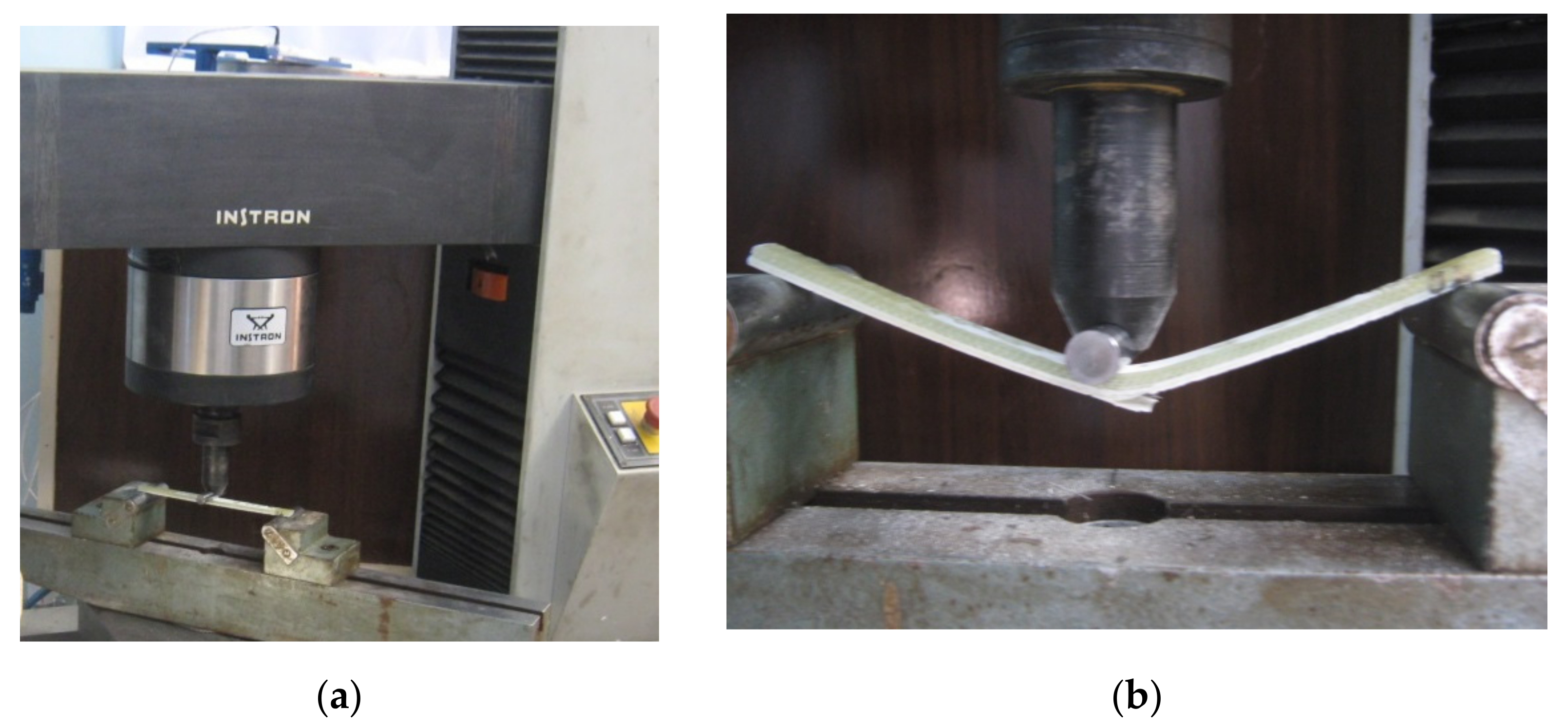
2.2.2. Mechanical Testing
3. Results and Discussion
3.1. Lay-Up and Microstructure
3.2. Material Behavior under Tensile Loading
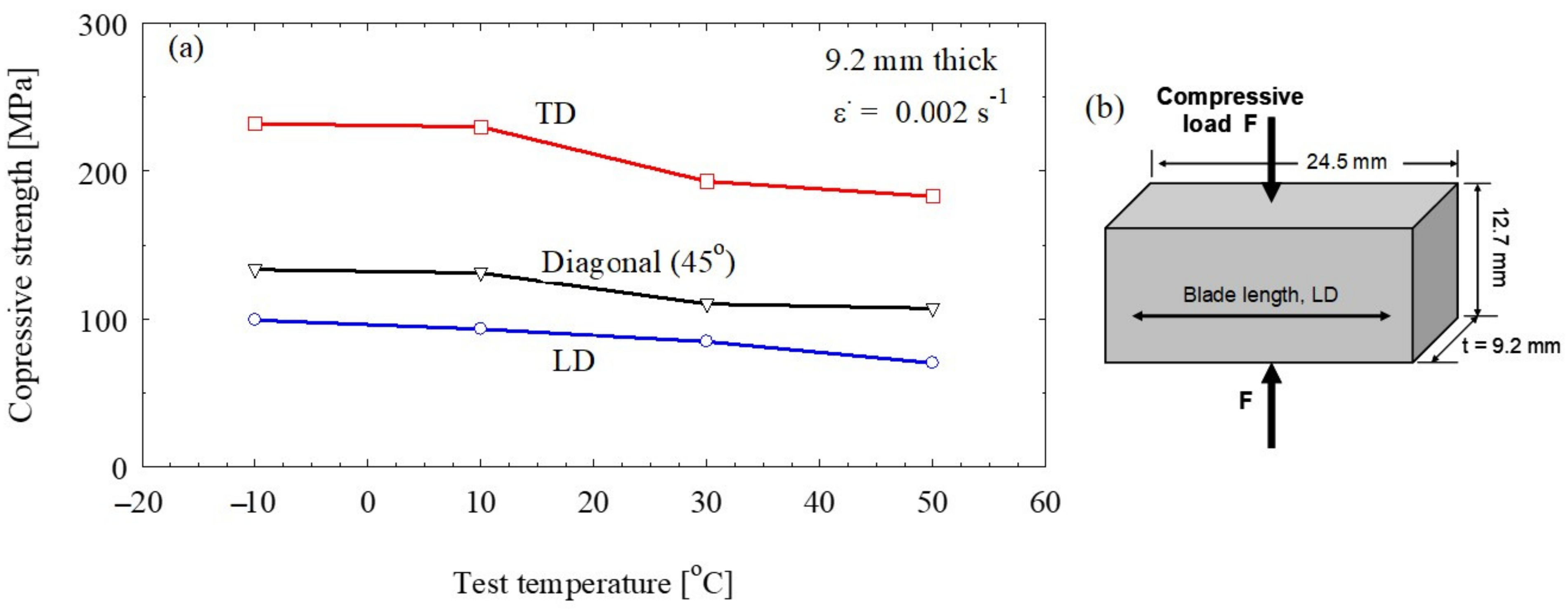
3.3. Compression Test Results
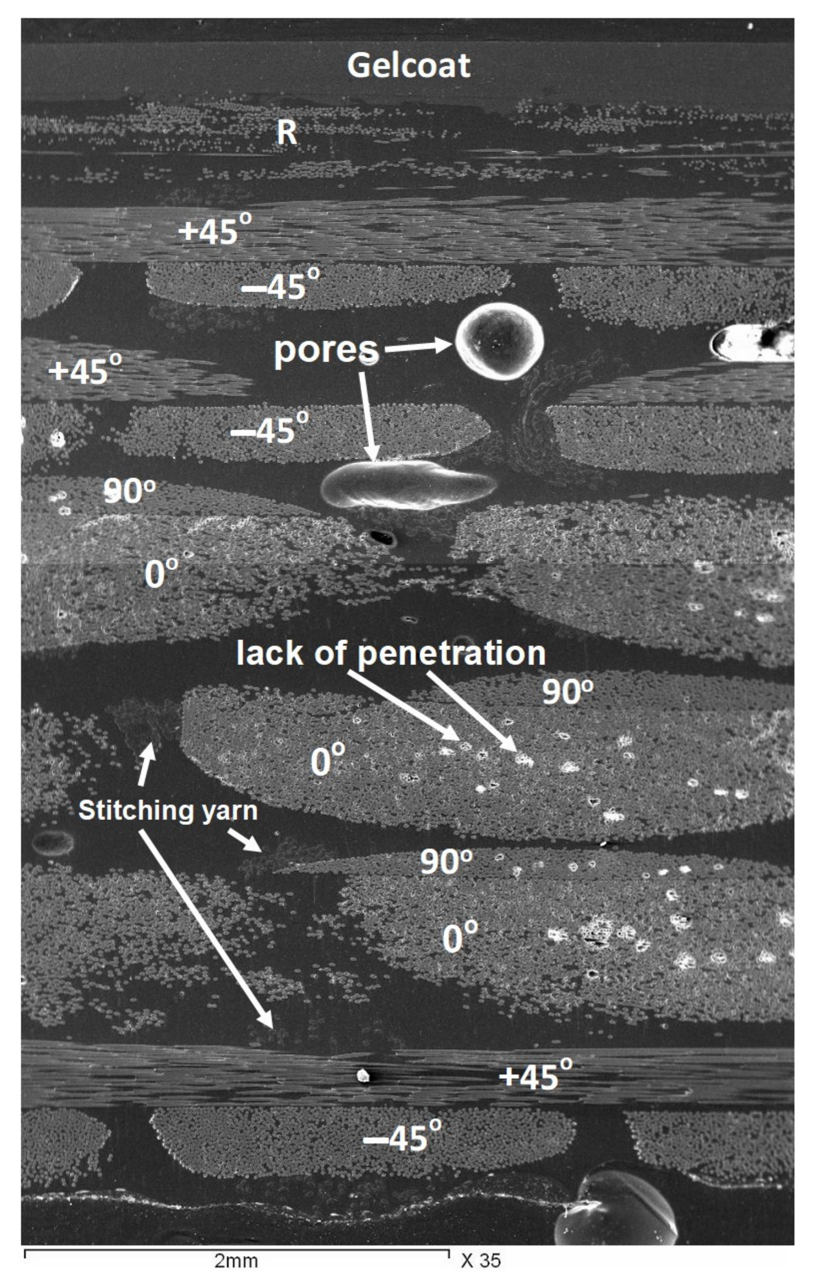
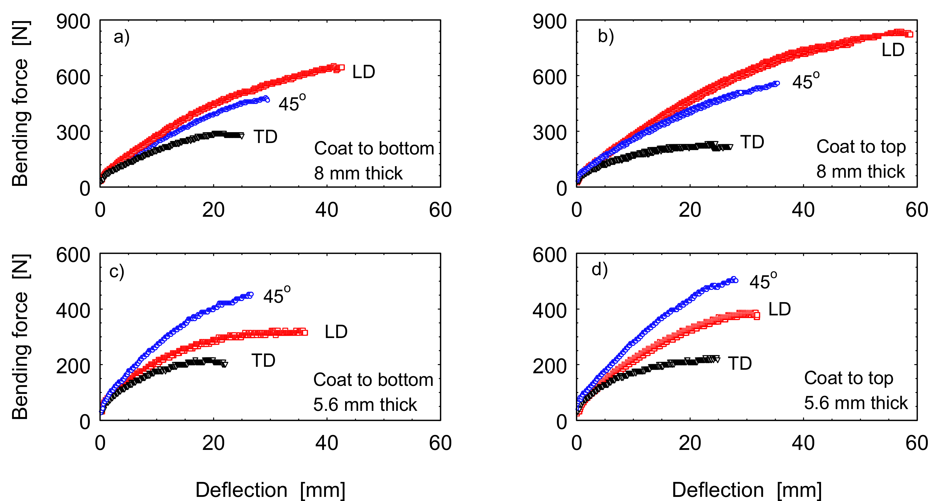
3.4. Three-Point Bending Behavior
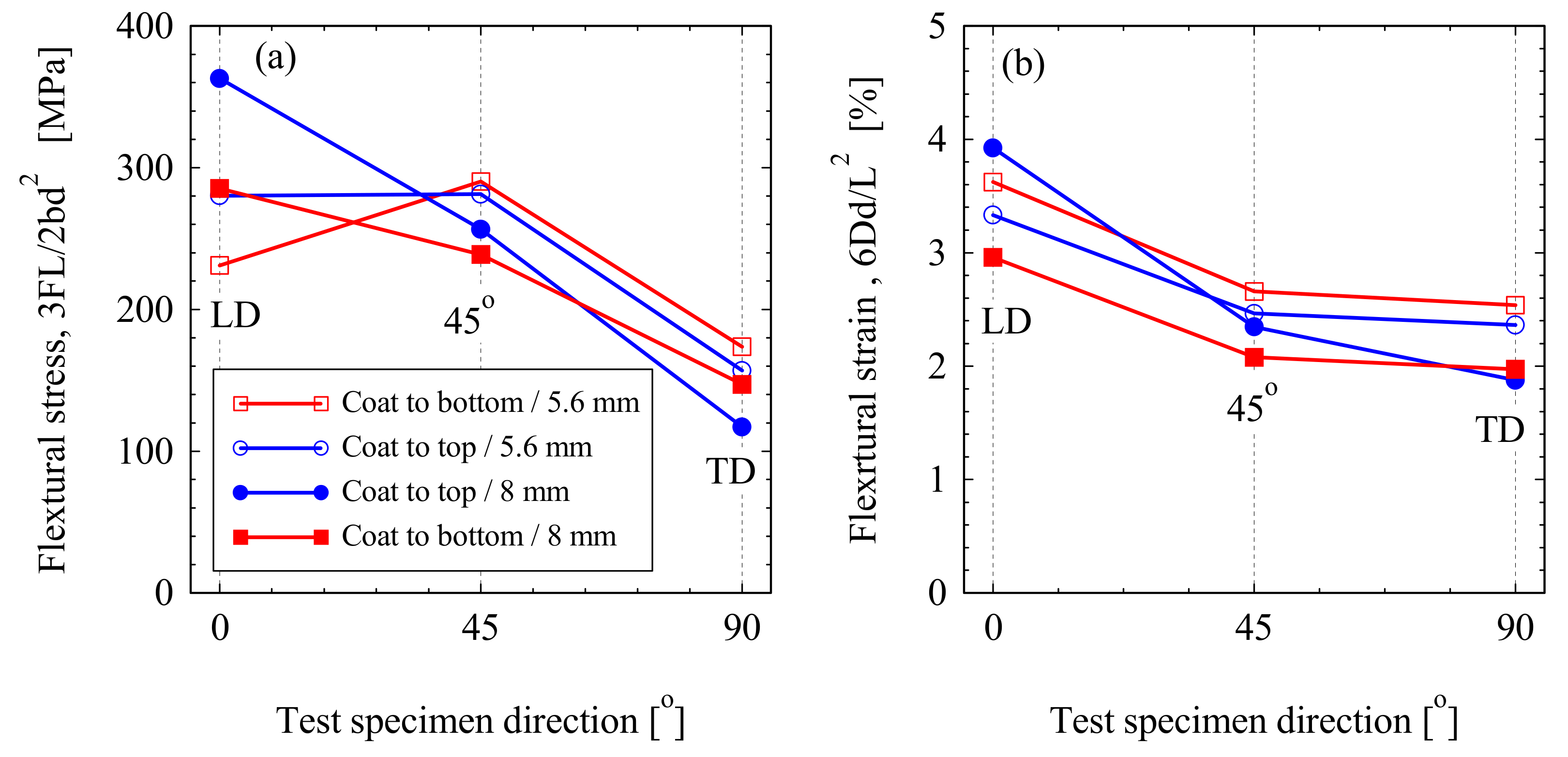
3.5. Effect of Fibers Orientation
3.6. Effect of Temperature on the Composites Mechanical Properties
4. Conclusions
- (1)
- The number of fiber fabric layers is decreasing along the blade length away from the root and the density of the fibers along the length is the highest (858 gm/mm2) and in the transverse direction is the lowest (83 gm/mm2).
- (2)
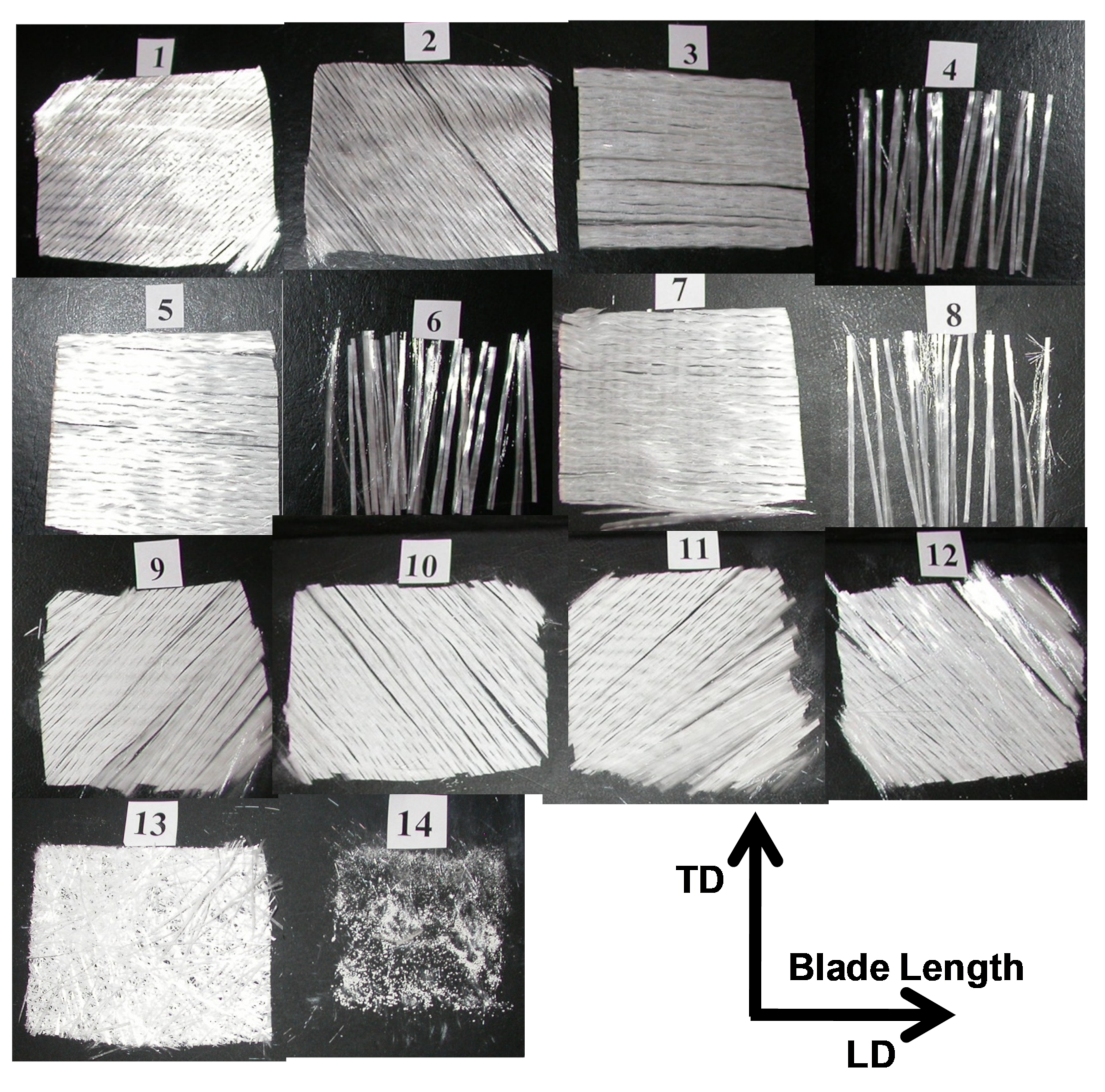
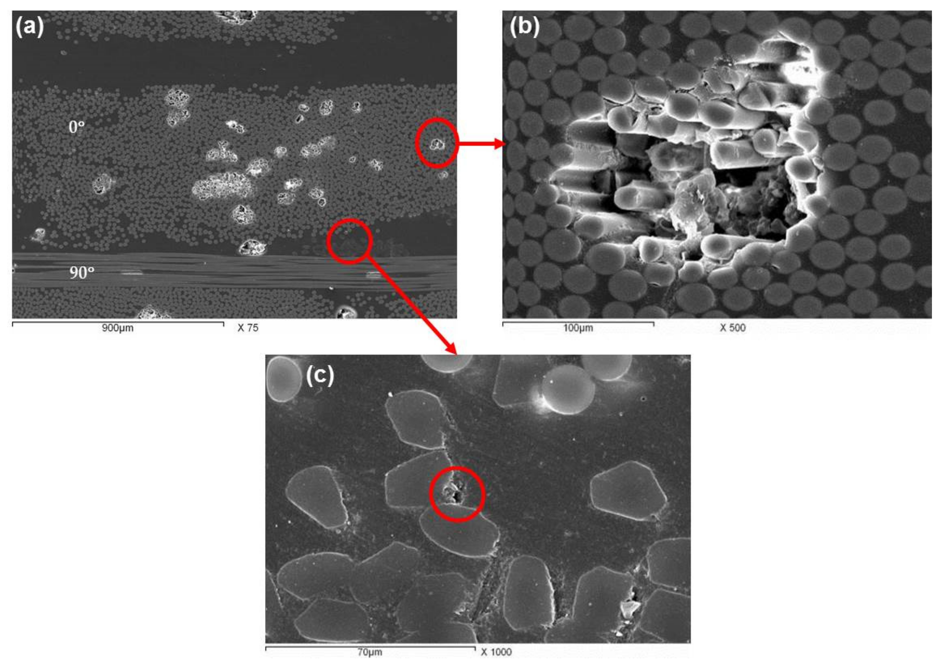
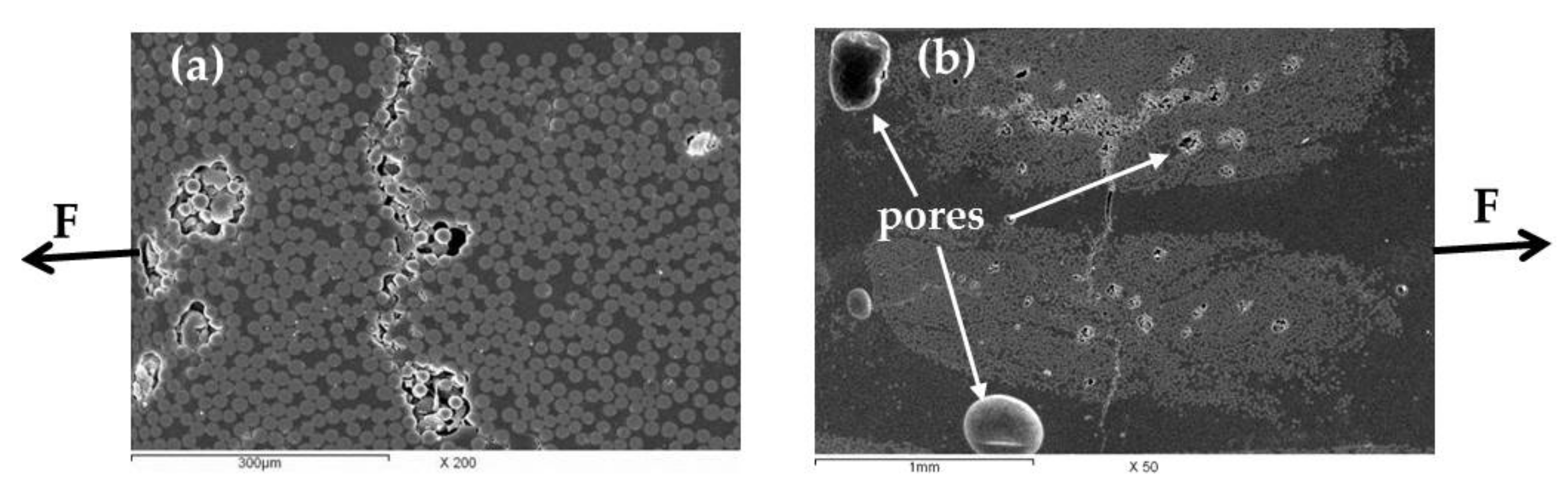
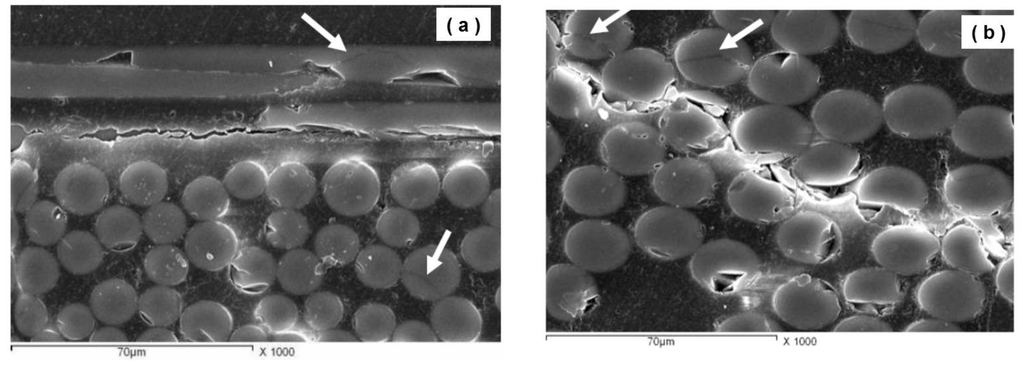
- The microstructure of the GFRP composite showed good wetting for the fiber by the polymer with some features of lack of penetration at the high density fiber bundles and some production porosity in the matrix.
- (3)
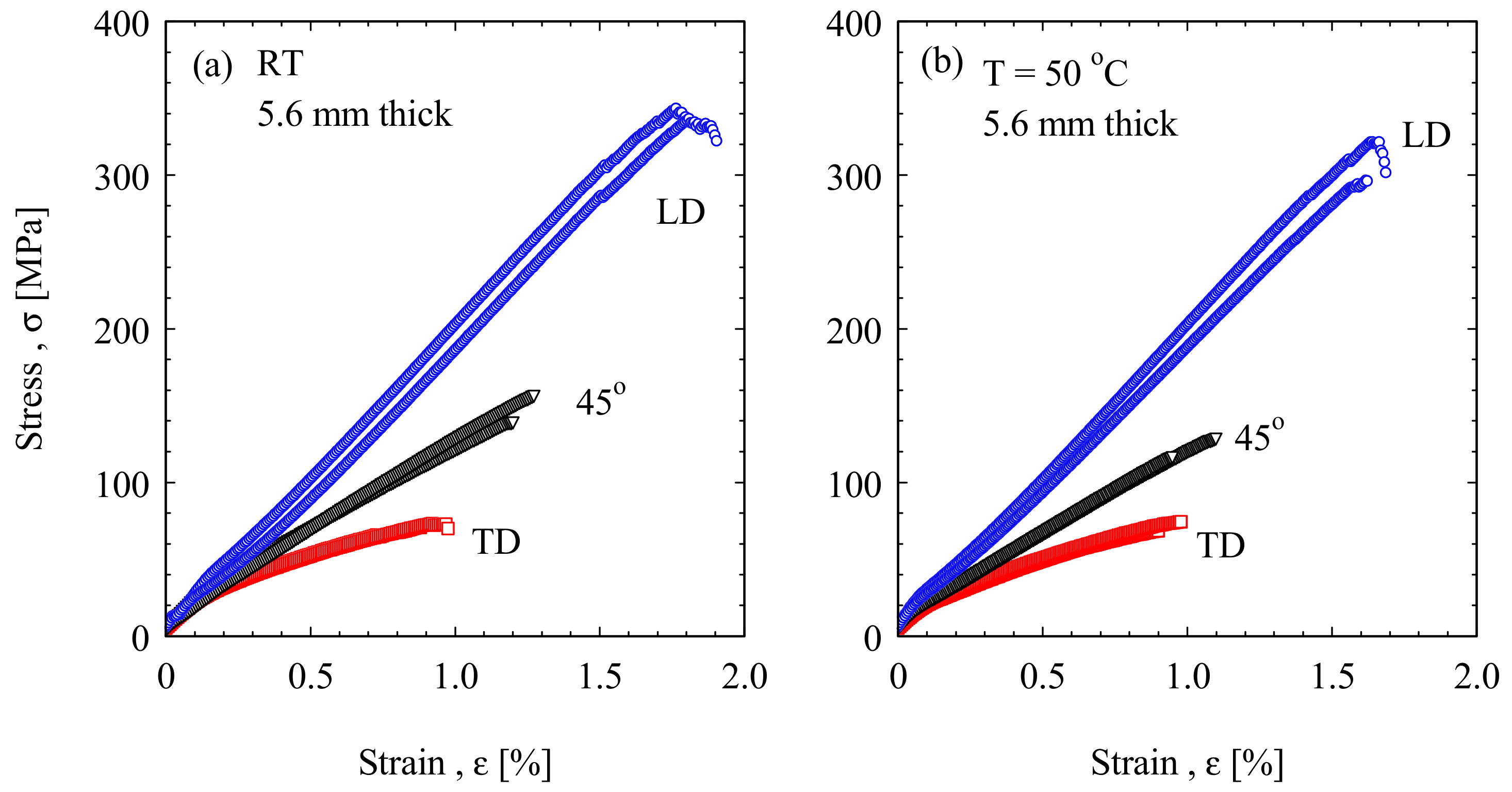
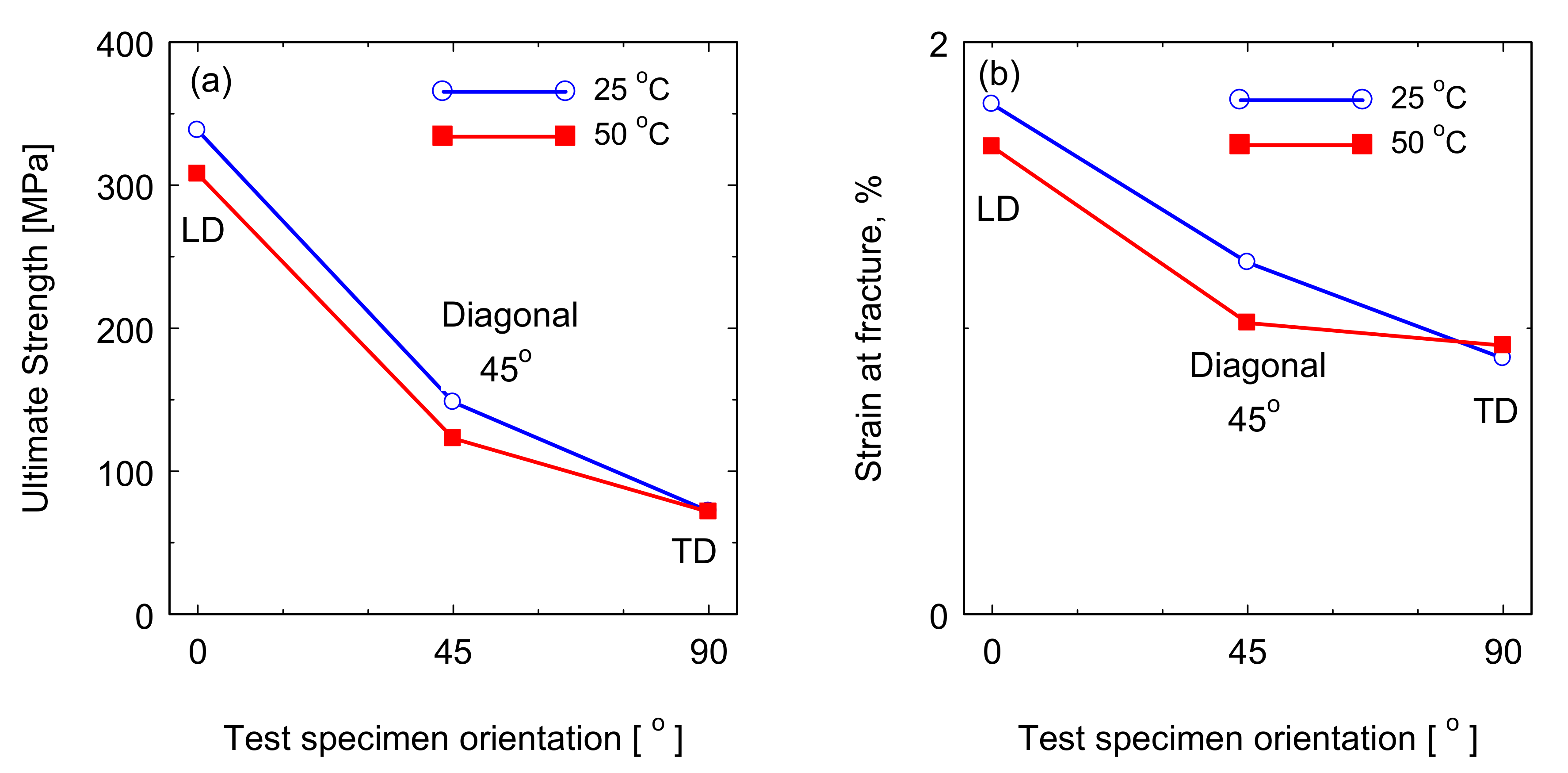
- The tensile properties at RT and high temperature are almost similar with the highest properties for the samples aligned with the blade length.
- (4)
- The compressive strength is highest at the transverse direction samples and lowest at the blade length direction and decreasing with the increase of the test temperature.
- (5)
- The bending properties are significantly affected by the fiber orientation with the highest properties for samples aligned with the blade length and the lowest for the samples with the transverse direction. The bending properties also affected by the gelcoat layer and the thickness of the sample.
- (6)
- Flexural loading has led to the following damage features: fiber fracture, through matrix cracking and cracking the fibers bundle.
Author Contributions
Funding
Institutional Review Board Statement
Informed Consent Statement
Data Availability Statement
Acknowledgments
Conflicts of Interest
References
- Brøndsted, P.; Lilholt, H.; Lystrup, A. Composite materials for wind power turbine blades. Annu. Rev. Mater. Res. 2005, 35, 505–538. [Google Scholar] [CrossRef]
- Hayman, B.; Wedel-Heinen, J.; Brøndsted, P. Materials Challenges and Future Wind Energy. MRS Bull. 2008, 33, 343–354. [Google Scholar] [CrossRef] [Green Version]
- Mishnaevsky, L.; Branner, K.; Petersen, H.N.; Beauson, J.; Mcgugan, M.; Sørensen, B.F. Materials for Wind Turbine Blades: An Overview. Mater. Rev. 2017, 10, 1285. [Google Scholar] [CrossRef] [PubMed] [Green Version]
- Ashby, M.F. Materials Selection in Mechanical Design; Elsevier Ltd.: Burlington, MA, USA, 2011; ISBN 9781856176637. [Google Scholar]
- Sutherland, H. Properties of Wind Turbine. Wind Energy 1999, 3, 1–34. [Google Scholar] [CrossRef] [Green Version]
- Akay, B.; Ragni, D.; Simão Ferreira, C.J.; van Bussel, G.J.W. Experimental investigation of the root flow in a horizontal axis wind turbine. Wind Energy 2013, 1–20. [Google Scholar] [CrossRef]
- Ataya, S.; Ahmed, M.M.Z. Damages of wind turbine blade trailing edge: Forms, location, and root causes. Eng. Fail. Anal. 2013, 35, 480–488. [Google Scholar] [CrossRef]
- Ataya, S.; Ahmed, M.; Ahmed, E. An Investigation of Damages in Low Power Wind Turbine Blades. J. Pet. Min. Eng. 2018, 20, 80–87. [Google Scholar] [CrossRef]
- Meng, H.; Lien, F.S.; Glinka, G.; Geiger, P. Study on fatigue life of bend-twist coupling wind turbine blade based on anisotropic beam model and stress-based fatigue analysis method. Compos. Struct. 2019, 208, 678–701. [Google Scholar] [CrossRef]
- Nijssen, R.P.L.; Brøndsted, P. Fatigue as a design driver for composite wind turbine blades. In Advances in Wind Turbine Blade Design and Materials; Woodhead Publishing Series in Energy; Brøndsted, P., Nijssen, R.P.L., Eds.; Woodhead Publishing: Sawston, UK, 2013; pp. 175–209. ISBN 978-0-85709-426-1. [Google Scholar]
- Kensche, C.W. Fatigue of Materials and Components for Wind Turbine Rotor Blades; European Commission ECSC-EC-EAEC: Brussels, Belgium, 1996; ISBN 92-827-4361-6. [Google Scholar]
- Bürkner, F.; Van Wingerde, A. Testing of rotor blades. In Proceedings of the 8th International Conference on Structural Dynamics (EURODYN), Leuven, Belgium, 4–6 July 2011; pp. 3511–3517. [Google Scholar]
- Bintu, A.; Vincze, G.; Picu, R.C.; Lopes, A.B. Effect of symmetric and asymmetric rolling on the mechanical properties of AA5182. Mater. Des. 2016, 100, 151–156. [Google Scholar] [CrossRef]
- Sayer, F.; Bürkner, F.; Buchholz, B.; Strobel, M.; Wingerde, A.M.; Busmann, H.; Seifert, H. Influence of a wind turbine service life on the mechanical properties of the material and the blade. Wind Energy 2013, 16, 163–174. [Google Scholar] [CrossRef]
- Zangana, S.; Epaarachchi, J.; Ferdous, W.; Leng, J. A novel hybridised composite sandwich core with Glass, Kevlar and Zylon fibres—Investigation under low-velocity impact. Int. J. Impact Eng. 2020, 137, 103430. [Google Scholar] [CrossRef]
- Zangana, S.; Epaarachchi, J.; Ferdous, W.; Leng, J.; Schubel, P. Behaviour of continuous fibre composite sandwich core under low-velocity impact. Thin-Walled Struct. 2021, 158, 107157. [Google Scholar] [CrossRef]
- Ferdous, W.; Manalo, A.; Peauril, J.; Salih, C.; Raghava Reddy, K.; Yu, P.; Schubel, P.; Heyer, T. Testing and modelling the fatigue behaviour of GFRP composites—Effect of stress level, stress concentration and frequency. Eng. Sci. Technol. Int. J. 2020, 23, 1223–1232. [Google Scholar] [CrossRef]
- Ferdous, W.; Manalo, A.; Wong, H.S.; Abousnina, R.; AlAjarmeh, O.S.; Zhuge, Y.; Schubel, P. Optimal design for epoxy polymer concrete based on mechanical properties and durability aspects. Constr. Build. Mater. 2020, 232, 117229. [Google Scholar] [CrossRef]
- Beauson, J.; Brøndsted, P. Wind Turbine Blades: An End of Life Perspective. In MARE-WINT: New Materials and Reliability in Offshore Wind Turbine Technology; Ostachowicz, W., McGugan, M., Schröder-Hinrichs, J.-U., Luczak, M., Eds.; Springer International Publishing: Cham, Switzerland, 2016; pp. 421–432. ISBN 978-3-319-39095-6. [Google Scholar]
- Cooperman, A.; Eberle, A.; Lantz, E. Wind turbine blade material in the United States: Quantities, costs, and end-of-life options. Resour. Conserv. Recycl. 2021, 168, 105439. [Google Scholar] [CrossRef]
- Liu, P.; Meng, F.; Barlow, C.Y. Wind turbine blade end-of-life options: An eco-audit comparison. J. Clean. Prod. 2019, 212, 1268–1281. [Google Scholar] [CrossRef] [Green Version]
- Kouloumpis, V.; Sobolewski, R.A.; Yan, X. Performance and life cycle assessment of a small scale vertical axis wind turbine. J. Clean. Prod. 2020, 247, 119520. [Google Scholar] [CrossRef]
- Liu, H.; Zhang, Z.; Jia, H.; Li, Q.; Liu, Y.; Leng, J. A novel method to predict the stiffness evolution of in-service wind turbine blades based on deep learning models. Compos. Struct. 2020, 252, 112702. [Google Scholar] [CrossRef]
- Habali, S.M.; Saleh, I.A. Local design, testing and manufacturing of small mixed airfoil wind turbine blades of glass fiber reinforced plastics: Part I: Design of the blade and root. Energy Convers. Manag. 2000, 41, 249–280. [Google Scholar] [CrossRef]
- Manwell, J.F.; McCowan, J.G.; Rogers, A.L. Wind Energy Explained: Theory, design and application. Wind Eng. 2006, 30, 169. [Google Scholar]
- Subrahmanian, K.P.; Dubouloz, F. Adhesives for bonding wind turbine blades. Reinf. Plast. 2009, 53, 26–29. [Google Scholar] [CrossRef]
- Yuhazri, M.Y.; Sihombing, H.; Zaimi, Z.A.M.; Nilson, G.C.H. A review on gelcoat used in laminated composite structure. Int. J. Res. Eng. Technol. 2015, 4, 49–58. [Google Scholar]
- Guidelines for Design of Wind Turbines, 2nd ed.; DNV Risø National Laboratory: Roskilde, Denmark, 2013; ISBN 8755028705.
- Saribiyik, M.; Caglar, N. Determination of mechanical properties of pultruded grp box section using a “short” tensile coupon. Gazi Univ. J. Sci. 2003, 16, 105–113. [Google Scholar]
- Salekeen, S.; Jones, D.L. Fatigue response of thick section fiberglass/epoxy composites. Compos. Struct. 2007, 79, 119–124. [Google Scholar] [CrossRef]
- Javaid, U.; Khan, Z.M.; Khan, M.B.; Bassyouni, M.; Abdel-Hamid, S.M.S.; Abdel-Aziz, M.H.; Ul Hasan, S.W. Fabrication and thermo-mechanical characterization of glass fiber/vinyl ester wind turbine rotor blade. Compos. Part B Eng. 2016, 91, 257–266. [Google Scholar] [CrossRef]
- Abdel-Wahab, A.A.; Ataya, S.; Silberschmidt, V.V. Temperature-dependent mechanical behaviour of PMMA: Experimental analysis and modelling. Polym. Test. 2017, 58, 86–95. [Google Scholar] [CrossRef] [Green Version]
- Guo, H.; Lu, C.; Chen, Y.; Tao, J.; Chen, L. Thermal—Mechanical Coupling Behavior of Directional Polymethylmethacrylate under Tension and Compression. Polymers 2018, 10, 1279. [Google Scholar] [CrossRef] [PubMed] [Green Version]
- Chung, D.D.L. Composite Materials Science and Applications, 2nd ed.; Springer: Berlin/Heidelberg, Germany, 2010; ISBN 978-1-84882-830-8. [Google Scholar]
- Zayed, E.M.; El-Tayeb, N.S.M.; Ahmed, M.M.Z.; Rashad, R.M. Development and Characterization of AA5083 Reinforced with SiC and Al2O3 Particles by Friction Stir Processing. In Advanced Structured Materials; Springer International Publishing: Cham, Switzerland, 2019; Volume 92. [Google Scholar] [CrossRef]
- Bakkar, A.; Ahmed, M.M.Z.; Alsaleh, N.A.; Seleman, M.M.E.; Ataya, S. Microstructure, Wear, and Corrosion Characterization of High TiC Content Inconel 625 Matrix Composites. J. Mater. Res. Technol. 2019, 8, 1102–1110. [Google Scholar] [CrossRef]


| Samples | Fiber Density (wt.%) | Lay-Up Sequence of GFRP | ||||||||||
|---|---|---|---|---|---|---|---|---|---|---|---|---|
| 1,2 | 3,4 | 5,6 | 7,8 | 9,10 | 11,12 | 13,14 | 15,16 | 17,18 | 19,20 | |||
| Sample 1 (S1) | 59 | ±45° | 0°/90° | 0°/90° | 0°/90° | ±45° | R/G | − | − | − | − | |
| Sample 2 (S2) | 60 | ±45° | 0°/90° | 0°/90° | 0°/90° | ±45° | ±45° | R/G | − | − | − | |
| Sample 3 (S3) | 55 | ±45° | 0°/90° | 0°/90° | 0°/90° | 0°/90° | 0°/90° | 0°/90° | ±45° | ±45° | R/G | |
| Orientation | Random | +45° | −45° | 0° | 90° |
|---|---|---|---|---|---|
| Fibers density (gm/m2) | 161 | 598 | 598 | 858 | 83 |
Publisher’s Note: MDPI stays neutral with regard to jurisdictional claims in published maps and institutional affiliations. |
© 2021 by the authors. Licensee MDPI, Basel, Switzerland. This article is an open access article distributed under the terms and conditions of the Creative Commons Attribution (CC BY) license (https://creativecommons.org/licenses/by/4.0/).
Share and Cite
Ahmed, M.M.Z.; Alzahrani, B.; Jouini, N.; Hessien, M.M.; Ataya, S. The Role of Orientation and Temperature on the Mechanical Properties of a 20 Years Old Wind Turbine Blade GFR Composite. Polymers 2021, 13, 1144. https://doi.org/10.3390/polym13071144
Ahmed MMZ, Alzahrani B, Jouini N, Hessien MM, Ataya S. The Role of Orientation and Temperature on the Mechanical Properties of a 20 Years Old Wind Turbine Blade GFR Composite. Polymers. 2021; 13(7):1144. https://doi.org/10.3390/polym13071144
Chicago/Turabian StyleAhmed, Mohamed M. Z., Bandar Alzahrani, Nabil Jouini, Mahmoud M. Hessien, and Sabbah Ataya. 2021. "The Role of Orientation and Temperature on the Mechanical Properties of a 20 Years Old Wind Turbine Blade GFR Composite" Polymers 13, no. 7: 1144. https://doi.org/10.3390/polym13071144