Preparation of Boron Nitride-Coated Carbon Fibers and Synergistic Improvement of Thermal Conductivity in Their Polypropylene-Matrix Composites


Abstract
:
1. Introduction
- To simplify the synthesis of a BN microlayer on CFs by removing the adverse environmental effects of using urea in the boriding process, hence carrying out nitriding by using only a gaseous precursor in a high-temperature furnace.
- To measure the effects of BN coating on the thermal conductivity and electrical resistivity of the final PMC.
- To propose BN–CFs incorporated with GF as the reinforcing filler system for the fabrication of functional PMCs.
2. Experimental Details
2.1. Materials
2.2. Preparation of BN-Modified CFs
2.3. Fabrication of PMC Samples
2.4. Characterizations
2.4.1. Surface Characteristics
2.4.2. Thermal and Electrical Characteristics
3. Results and Discussion
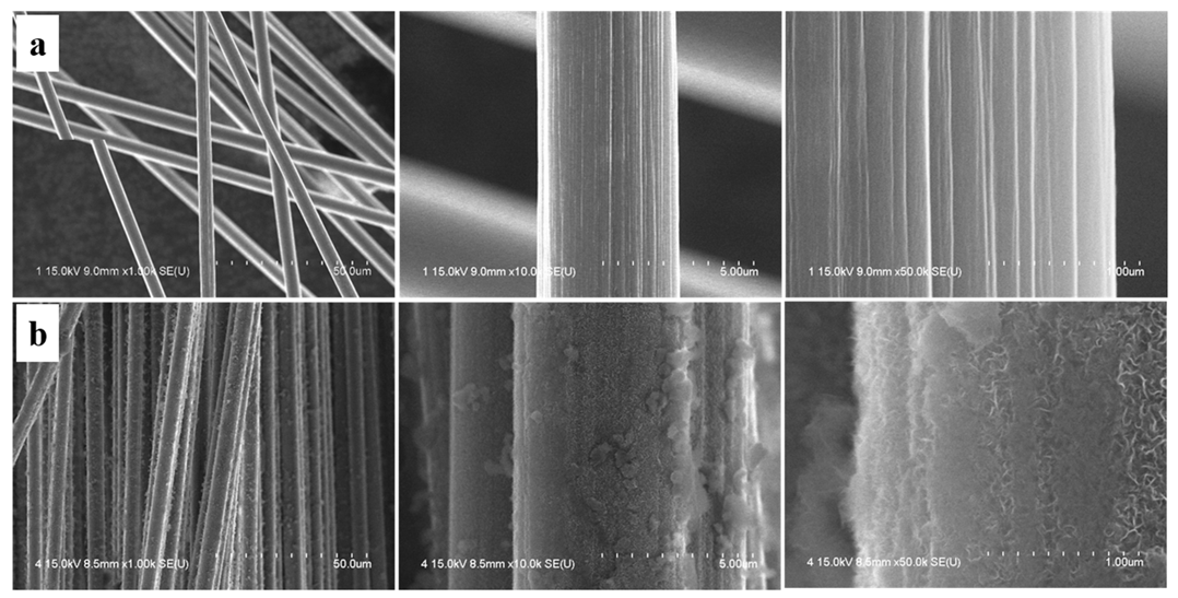
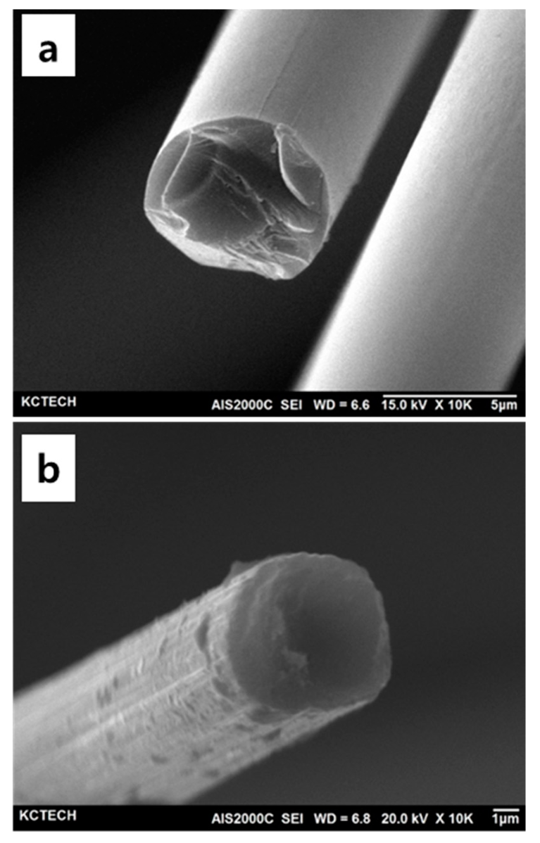
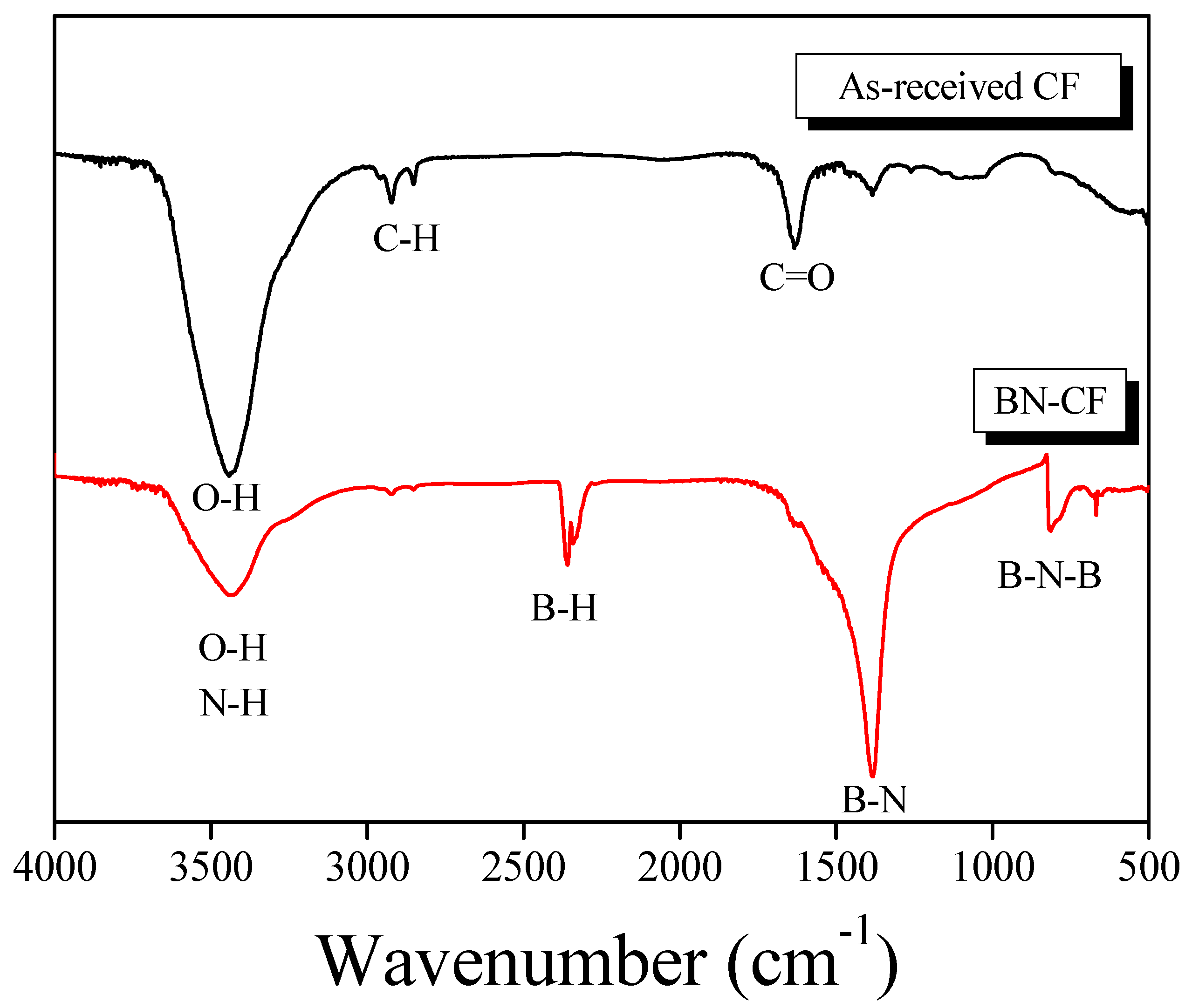
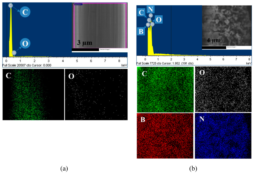
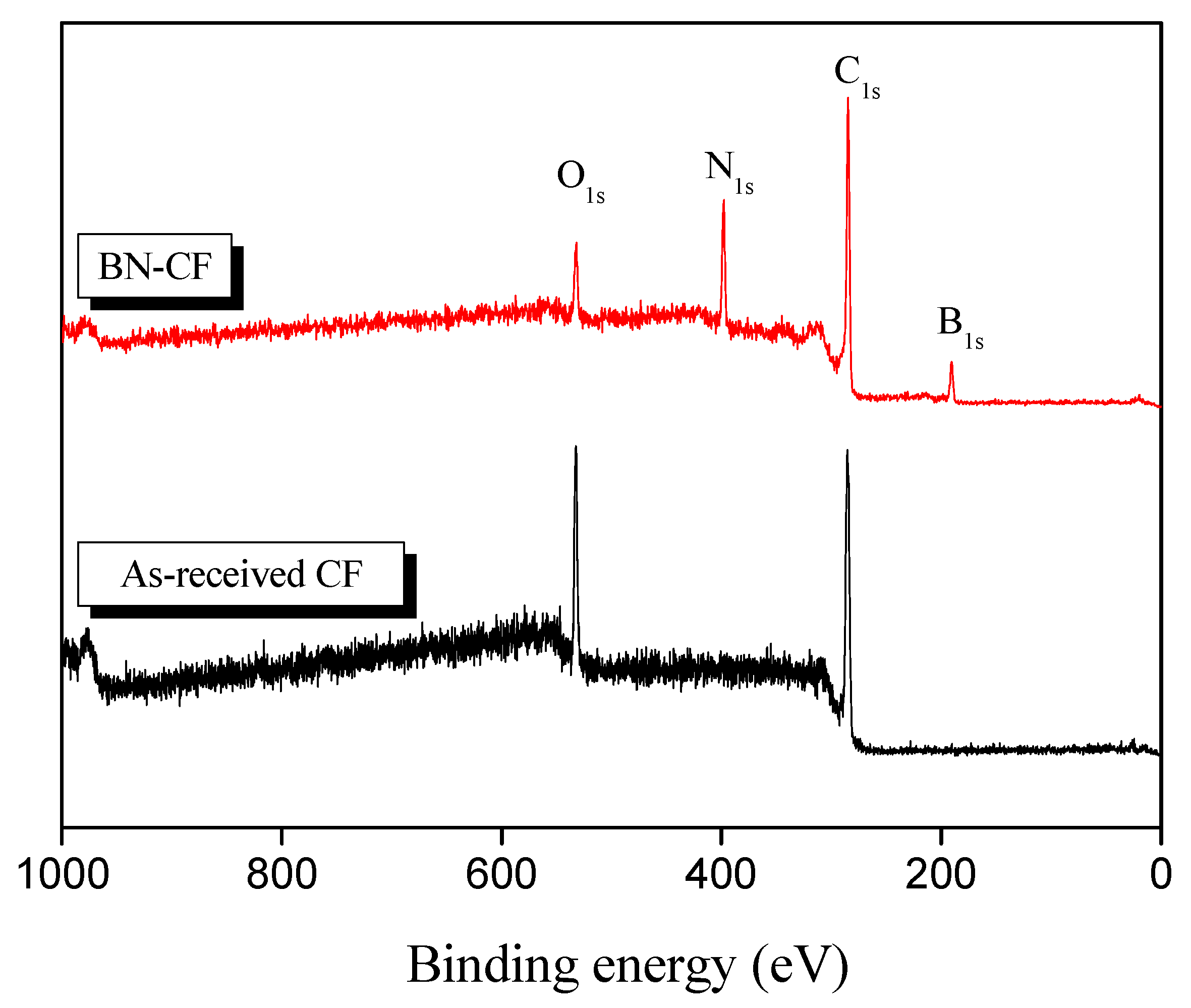
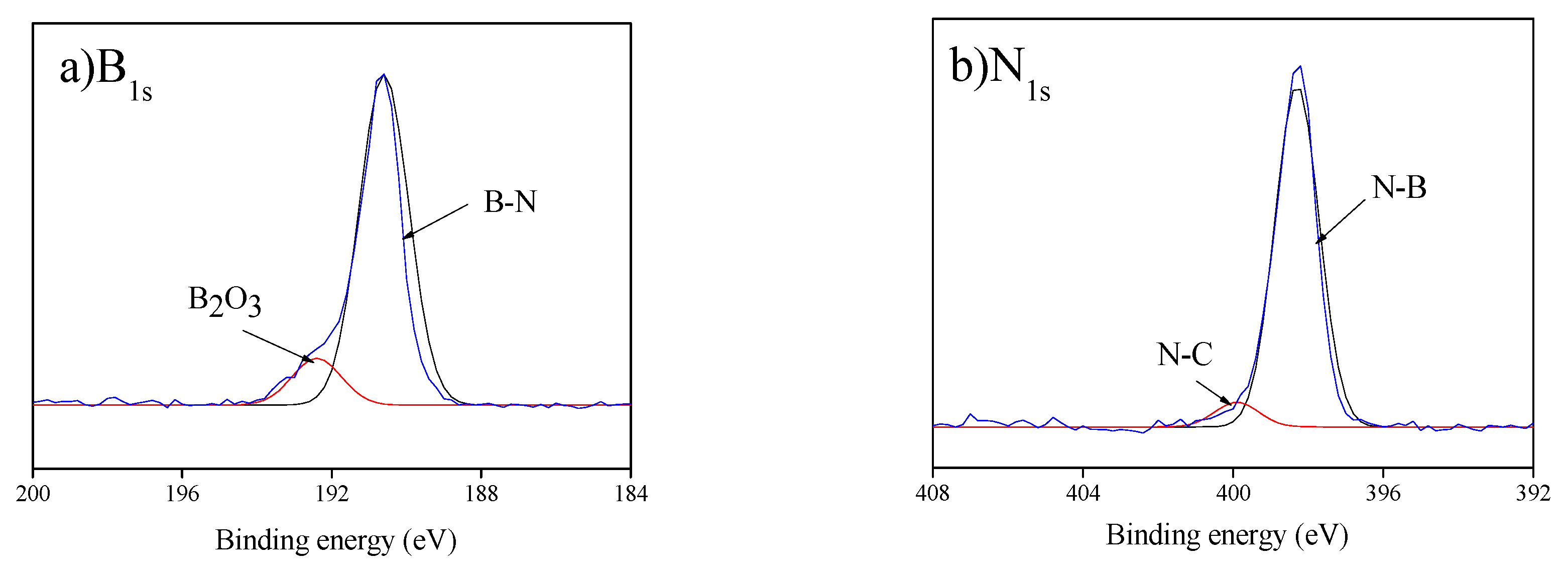
3.1. Surface Characteristics of BN–CFs
3.2. Thermal and Electrical Properties of BN–CFs
4. Conclusions
Author Contributions
Funding
Conflicts of Interest
References
- Zweben, C. Advances in composite materials for thermal management in electronic packaging. JOM 1998, 50, 47–51. [Google Scholar] [CrossRef]
- Badakhsh, A. A Study on Performance Characteristics of Polymer-Based Air-Cooled Heat Exchanger: From Material Design to Application. Master’s Thesis, Chonbuk National University, Jeollabuk-do, Korea, 2017. [Google Scholar]
- Badakhsh, A.; Lee, Y.M.; Rhee, K.Y.; Park, C.W.; An, K.H.; Kim, B.J. Improvement of thermal, electrical and mechanical properties of composites using a synergistic network of length controlled-CNTs and graphene nanoplatelets. Compos. B Eng. 2019, 175, 107075. [Google Scholar] [CrossRef]
- Chen, X.; Su, Y.; Reay, D.; Riffat, S. Recent research developments in polymer heat exchangers—A review. Renew. Sustain. Energy Rev. 2016, 60, 1367–1386. [Google Scholar] [CrossRef]
- Hussain, A.R.J.; Alahyari, A.A.; Eastman, S.A.; Thibaud-Erkey, C.; Johnston, S.; Sobkowicz, M.J. Review of polymers for heat exchanger applications: Factors concerning thermal conductivity. Appl. Therm. Eng. 2017, 113, 1118–1127. [Google Scholar] [CrossRef] [Green Version]
- Glade, H.; Moses, D.; Orth, T. Polymer Composite Heat Exchangers. In Innovative Heat Exchangers; Bart, H.J., Scholl, S., Eds.; Springer: Cham, Germany, 2018; pp. 53–116. [Google Scholar] [CrossRef]
- Badakhsh, A.; Park, C.W. From morphology of attrited copper/MWCNT hybrid fillers to thermal and mechanical characteristics of their respective polymer-matrix composites: An analytical and experimental study. J. Appl. Polym. Sci. 2017, 134, 45397. [Google Scholar] [CrossRef]
- Park, H.J.; Badakhsh, A.; Im, I.T.; Kim, M.S.; Park, C.W. Experimental study on the thermal and mechanical properties of MWCNT/polymer and Cu/polymer composites. Appl. Therm. Eng. 2016, 107, 907–917. [Google Scholar] [CrossRef]
- Rohani, H.; Badakhsh, A.; Park, C.W. Thermal performance of modified polymeric heatsinks as an alternative for aluminum in heat rejection systems. Appl. Therm. Eng. 2019, 159, 113823. [Google Scholar] [CrossRef]
- Ji, C.; Yan, C.; Wang, Y.; Xiong, S.; Zhou, F.; Li, Y.; Sun, R.; Wong, C.P. Thermal conductivity enhancement of CNT/MoS2/graphene-epoxy nanocomposites based on structural synergistic effects and interpenetrating network. Compos. B Eng. 2019, 163, 363–370. [Google Scholar] [CrossRef]
- Yan, C.; Yu, T.; Ji, C.; Kang, D.J.; Wang, N.; Sun, R.; Wong, C.P. Tailoring Highly Thermal Conductive Properties of Te/MoS2/Ag Heterostructure Nanocomposites Using a Bottom-Up Approach. Adv. Electron. Mater. 2019, 5, 1800548. [Google Scholar] [CrossRef] [Green Version]
- Wu, G.; Ma, L.; Jiang, H. The roles of surface wettability and roughness of carbon fibers in interfacial enhancement of silicone resin composites. Polym. Compos. 2019. [Google Scholar] [CrossRef]
- Tiwari, S.; Bijwe, J. Surface Treatment of Carbon Fibers—A Review. Procedia Technol. 2014, 14, 505–512. [Google Scholar] [CrossRef] [Green Version]
- Choi, W.K.; Kim, H.I.; Kang, S.J.; Lee, Y.S.; Han, J.H.; Kim, B.J. Mechanical interfacial adhesion of carbon fibers-reinforced polarized-polypropylene matrix composites: Effects of silane coupling agents. Carbon Lett. 2016, 17, 79–84. [Google Scholar] [CrossRef] [Green Version]
- Kim, D.K.; An, K.H.; Bang, Y.H.; Kwac, L.K.; Oh, S.Y.; Kim, B.J.K. Effects of electrochemical oxidation of carbon fibers on interfacial shear strength using a micro-bond method. Carbon Lett. 2016, 19, 32–39. [Google Scholar] [CrossRef] [Green Version]
- Mun, S.Y.; Lim, H.M.; Lee, S.H. Thermal and electrical properties of epoxy composite with expanded graphite-ceramic core-shell hybrids. Mater. Res. Bull. 2018, 97, 19–23. [Google Scholar] [CrossRef]
- Kim, H.H.; Han, W.; Lee, H.S.; Min, B.G.; Kim, B.J. Preparation and characterization of silicon nitride (SiN)-coated carbon fibers and their effects on thermal properties in composites. Mater. Sci. Eng. B 2015, 200, 132–138. [Google Scholar] [CrossRef]
- Ghasali, E.; Alizadeh, M.; Pakseresht, A.H.; Ebadzadeh, T. Preparation of silicon carbide/carbon fiber composites through high-temperature spark plasma sintering. J. Asian Ceram. Soc. 2017, 5, 472–478. [Google Scholar] [CrossRef] [Green Version]
- Kumar, R.; Bhargava, P. In situ-growth of silica nanowires in ceramic carbon composites. J. Asian Ceram. Soc. 2017, 5, 304–312. [Google Scholar] [CrossRef]
- Xiaoyan, Z.; Zengyi, T.; Beidi, Z.; Erhua, Z.; Kun, C. Investigation of laser cladding ceramic-metal composite coatings: Processing modes and mechanisms. Surf. Coat. Technol. 1996, 79, 209–217. [Google Scholar] [CrossRef]
- Lii, D.F.; Huang, J.L.; Tsui, L.J.; Lee, S.M. Formation of BN films on carbon fibers by dip-coating. Surf. Coat. Technol. 2002, 150, 269–276. [Google Scholar] [CrossRef]
- Zheng, Y.; Wang, S. Synthesis of boron nitride coatings on quartz fibers: Thickness control and mechanism research. Appl. Surf. Sci. 2011, 257, 10752–10757. [Google Scholar] [CrossRef]
- Zhou, W.; Xiao, P.; Li, Y.; Zhou, L. Dielectric properties of BN modified carbon fibers by dip-coating. Ceram. Int. 2013, 39, 6569–6576. [Google Scholar] [CrossRef]
- Krivoshapkin, P.V.; Mishakov, I.V.; Vedyagin, A.A.; Bauman, Y.I.; Krivoshapkina, E.F. Synthesis and characterization of carbon/ceramic composite materials for environmental applications. Compos. Commun. 2017, 6, 17–19. [Google Scholar] [CrossRef]
- Deb, B.; Bhattacharjee, B.; Ganguli, A.; Chaudhuri, S.; Pal, A.K. Boron nitride films synthesized by RF plasma CVD of borane–ammonia and nitrogen. Mater. Chem. Phys. 2002, 76, 130–136. [Google Scholar] [CrossRef]
- Li, J.S.; Zhang, C.R.; Li, B. Preparation and characterization of boron nitride coatings on carbon fibers from borazine by chemical vapor deposition. Appl. Surf. Sci. 2011, 257, 7752–7757. [Google Scholar] [CrossRef]
- Pippel, E.; Woltersdorf, J.; Dietrich, D.; Stöckel, S.; Weise, K.; Marx, G. CVD-coated boron nitride on continuous silicon carbide fibres: Structure and nanocomposition. J. Eur. Ceram. Soc. 2000, 20, 1837–1844. [Google Scholar] [CrossRef]
- Wang, H.; Zhang, S.; Li, Y.; Sun, D. Bias effect on microstructure and mechanical properties of magnetron sputtered nanocrystalline titanium carbide thin films. Thin Solid Film. 2008, 516, 5419–5423. [Google Scholar] [CrossRef]
- Lin, J.; Moore, J.J.; Mishra, B.; Pinkas, M.; Sproul, W.D.; Rees, J.A. Effect of asynchronous pulsing parameters on the structure and properties of CrAlN films deposited by pulsed closed field unbalanced magnetron sputtering (P-CFUBMS). Surf. Coat. Technol. 2008, 202, 1418–1436. [Google Scholar] [CrossRef]
- Chung, D.D.L. Materials for thermal conduction. Appl. Therm. Eng. 2001, 21, 1593–1605. [Google Scholar] [CrossRef]
- Hu, J.Q.; Lu, Q.Y.; Tang, K.B.; Yu, S.H.; Qian, Y.T.; Zhou, G.E.; Liu, X.M.; Wu, J.X. Synthesis and Characterization of Nanocrystalline Boron Nitride. J. Solid State Chem. 1999, 148, 325–328. [Google Scholar] [CrossRef]
- Wu, Z.; Li, J.; Wei, Y.; Huang, Z.; Yan, X.; Zhang, J. Influence of nano boron nitride (BN) on electric corrosion of fluororesin based super hydrophobic coatings for insulators. In Proceedings of the 2016 IEEE International Conference on High Voltage Engineering and Application (ICHVE), Chengdu, China, 19–22 September 2016; pp. 1–4. [Google Scholar]
- Thakur, V.K.; Vennerberg, D.; Kessler, M.R. Green Aqueous Surface Modification of Polypropylene for Novel Polymer Nanocomposites. ACS Appl. Mater. Interfaces 2014, 6, 9349–9356. [Google Scholar] [CrossRef] [Green Version]
- Michalska-Pożoga, I.; Rydzkowski, T.; Mazur, P.; Sadowska, O.; Thakur, V.K. A study on the thermodynamic changes in the mixture of polypropylene (PP) with varying contents of technological and post-user recyclates for sustainable nanocomposites. Vacuum 2017, 146, 641–648. [Google Scholar] [CrossRef]
- Kim, S.K.; Cho, H.; Kim, M.J.; Lee, H.J.; Park, J.H.; Lee, Y.B.; Kim, H.C.; Yoon, C.W.; Nam, S.W.; Kang, S.O. Efficient catalytic conversion of ammonia borane to borazine and its use for hexagonal boron nitride (white graphene). J. Mater. Chem. A 2013, 1, 1976–1981. [Google Scholar] [CrossRef]
- Chatterjee, S.; Kim, M.J.; Zakharov, D.N.; Kim, S.M.; Stach, E.A.; Maruyama, B.; Sneddon, L.G. Syntheses of Boron Nitride Nanotubes from Borazine and Decaborane Molecular Precursors by Catalytic Chemical Vapor Deposition with a Floating Nickel Catalyst. Chem. Mater. 2012, 24, 2872–2879. [Google Scholar] [CrossRef]
- Churchard, A.J.; Cyranski, M.K.; Dobrzycki, L.; Budzianowski, A.; Grochala, W. Nickel macrocycles with complex hydrides-new avenues for hydrogen storage research. Energy Environ. Sci. 2010, 3, 1973–1978. [Google Scholar] [CrossRef]
- Moreno, H.; Caicedo, J.C.; Amaya, C.; Muñoz-Saldaña, J.; Yate, L.; Esteve, J.; Prieto, P. Enhancement of surface mechanical properties by using TiN[BCN/BN]n/c-BN multilayer system. Appl. Surf. Sci. 2010, 257, 1098–1104. [Google Scholar] [CrossRef]
- Zhang, X.; Deng, J.; Wang, L.; Wang, X.; Yao, Q.; Chen, G.; He, D. Phase transformation in BN films by nitrogen-protected annealing at atmospheric pressure. Appl. Surf. Sci. 2008, 254, 7109–7113. [Google Scholar] [CrossRef]
- Phani, A.R. Thin films of boron nitride grown by CVD. Bull. Mater. Sci. 1994, 17, 219–224. [Google Scholar] [CrossRef]
- Termoss, H.; Toury, B.; Brioude, A.; Dazord, J.; Le Brusq, J.; Miele, P. High purity boron nitride thin films prepared by the PDCs route. Surf. Coat. Technol. 2007, 201, 7822–7828. [Google Scholar] [CrossRef]
- Huang, F.L.; Cao, C.B.; Xiang, X.; Lv, R.T.; Zhu, H.S. Synthesis of hexagonal boron carbonitride phase by solvothermal method. Diam. Relat. Mater. 2004, 13, 1757–1760. [Google Scholar] [CrossRef]
- Shen, L.; Tan, B.J.; Willis, W.S.; Galasso, F.S.; Suib, S.L. Characterization of Dip-Coated Boron Nitride on Silicon Carbide Fibers. J. Am. Ceram. Soc. 1994, 77, 1011–1016. [Google Scholar] [CrossRef]
- Kim, K.W.; Lee, H.M.; An, J.H.; Chung, D.C.; An, K.H.; Kim, B.J. Recycling and characterization of carbon fibers from carbon fiber reinforced epoxy matrix composites by a novel super-heated-steam method. J. Environ. Manag. 2017, 203, 872–879. [Google Scholar] [CrossRef]
- Das, M.; Basu, A.K.; Ghatak, S.; Joshi, A.G. Carbothermal synthesis of boron nitride coating on PAN carbon fiber. J. Eur. Ceram. Soc. 2009, 29, 2129–2134. [Google Scholar] [CrossRef]
- Berman, R. Heat conductivity of non-metallic crystals. Contemp. Phys. 1973, 14, 101–117. [Google Scholar] [CrossRef]


| Sample | Elemental Composition (%) | |||
|---|---|---|---|---|
| O1s | C1s | B1s | N1s | |
| As-received CF | 20.55 | 79.45 | - | - |
| BN–CF | 8.30 | 61.93 | 14.75 | 15.02 |
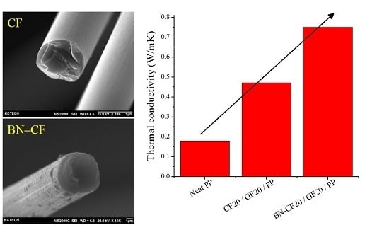
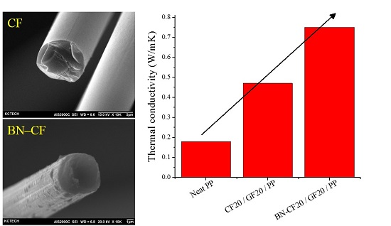
| Sample | Thermal Conductivity (W/mK) | Electrical Resistivity (Ω.cm) |
|---|---|---|
| Neat PP | 0.18 | - |
| CF20/GF20/PP | 0.47 | 4.72 |
| BN–CF20/GF20/PP | 0.75 | 37.84 |
| Sample | Electrical Resistivity (Ω.cm) |
|---|---|
| As-received CF | 2.76 × 10⁻² |
| BN–CF | 2.80 × 100 |
© 2019 by the authors. Licensee MDPI, Basel, Switzerland. This article is an open access article distributed under the terms and conditions of the Creative Commons Attribution (CC BY) license (http://creativecommons.org/licenses/by/4.0/).
Share and Cite
Badakhsh, A.; Han, W.; Jung, S.-C.; An, K.-H.; Kim, B.-J. Preparation of Boron Nitride-Coated Carbon Fibers and Synergistic Improvement of Thermal Conductivity in Their Polypropylene-Matrix Composites. Polymers 2019, 11, 2009. https://doi.org/10.3390/polym11122009
Badakhsh A, Han W, Jung S-C, An K-H, Kim B-J. Preparation of Boron Nitride-Coated Carbon Fibers and Synergistic Improvement of Thermal Conductivity in Their Polypropylene-Matrix Composites. Polymers. 2019; 11(12):2009. https://doi.org/10.3390/polym11122009
Chicago/Turabian StyleBadakhsh, Arash, Woong Han, Sang-Chul Jung, Kay-Hyeok An, and Byung-Joo Kim. 2019. "Preparation of Boron Nitride-Coated Carbon Fibers and Synergistic Improvement of Thermal Conductivity in Their Polypropylene-Matrix Composites" Polymers 11, no. 12: 2009. https://doi.org/10.3390/polym11122009