Characteristics, Compression, and Buffering Performance of Pomelo-Like Hierarchical Capsules Containing Shear Thickening Fluid


Abstract
:1. Introduction
2. Experimental Section
2.1. Materials and Methods
2.2. Preparation of STF
2.3. Preparation of STF Capsules
2.4. Measurements and Characterizations
3. Results and Discussion
3.1. Characterization of STF Capsules
3.2. Effect of Capsule Size on Thermal Stability
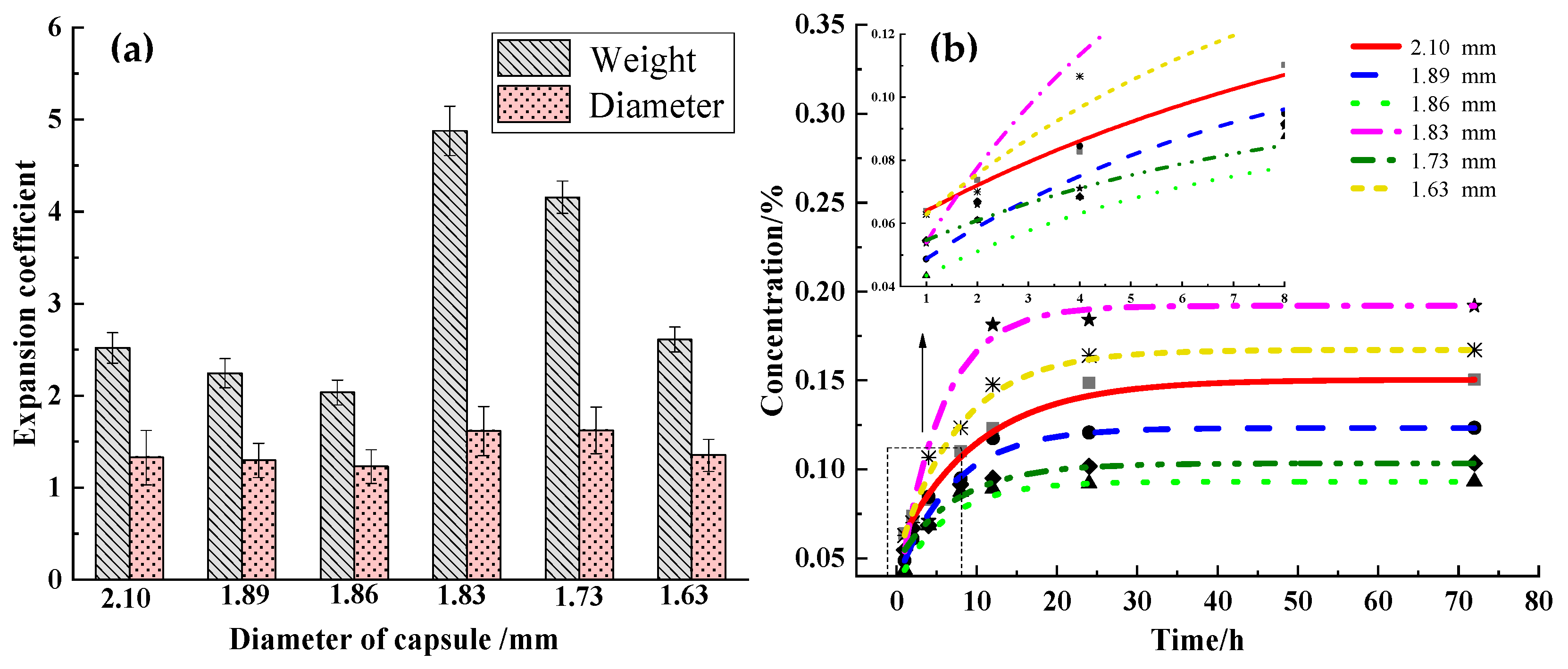
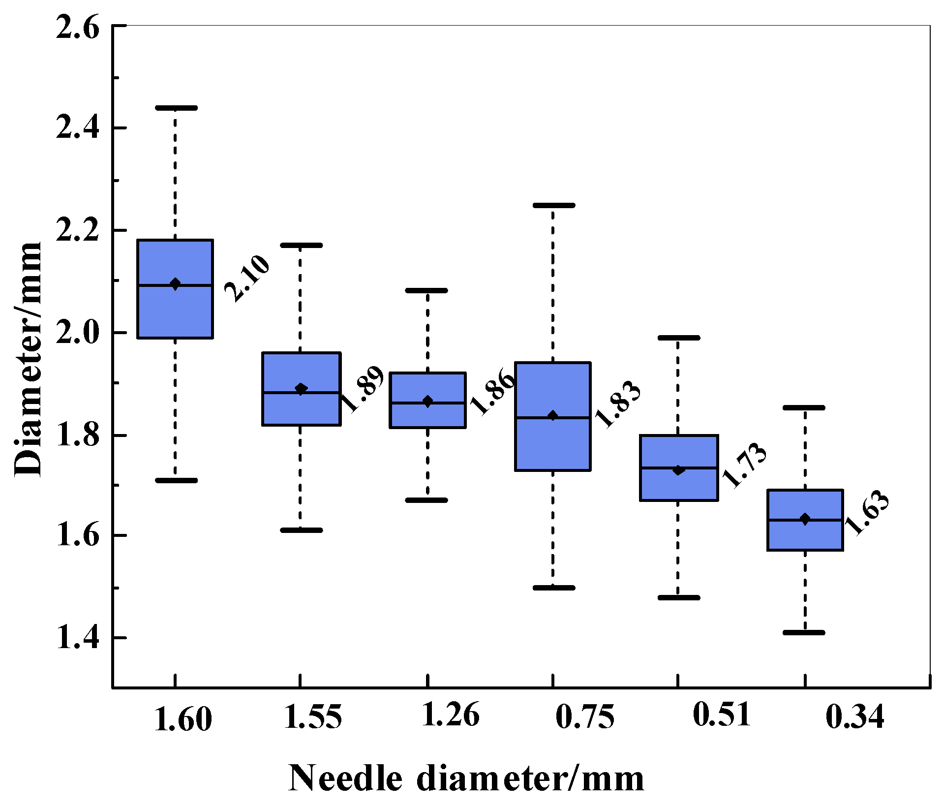
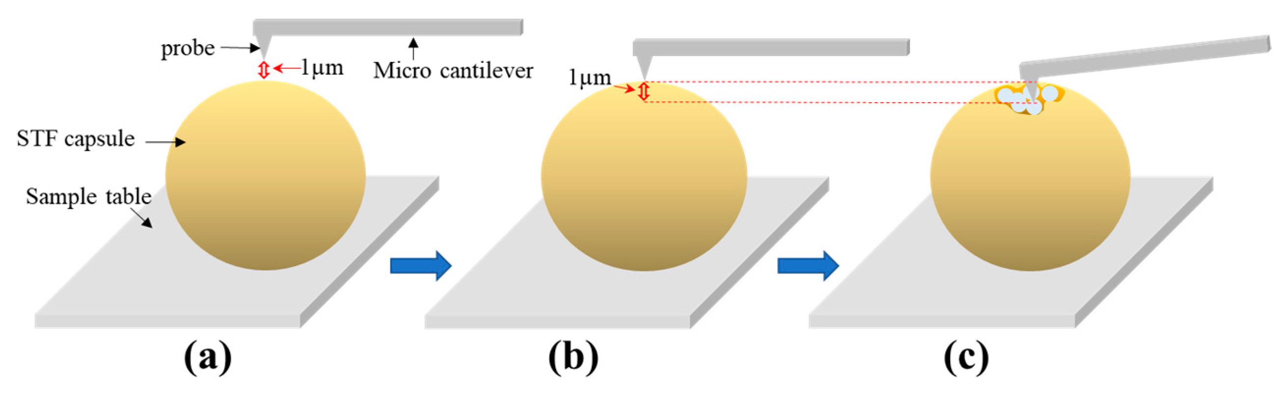
3.3. Effect of Capsule Size on Capsule Strength
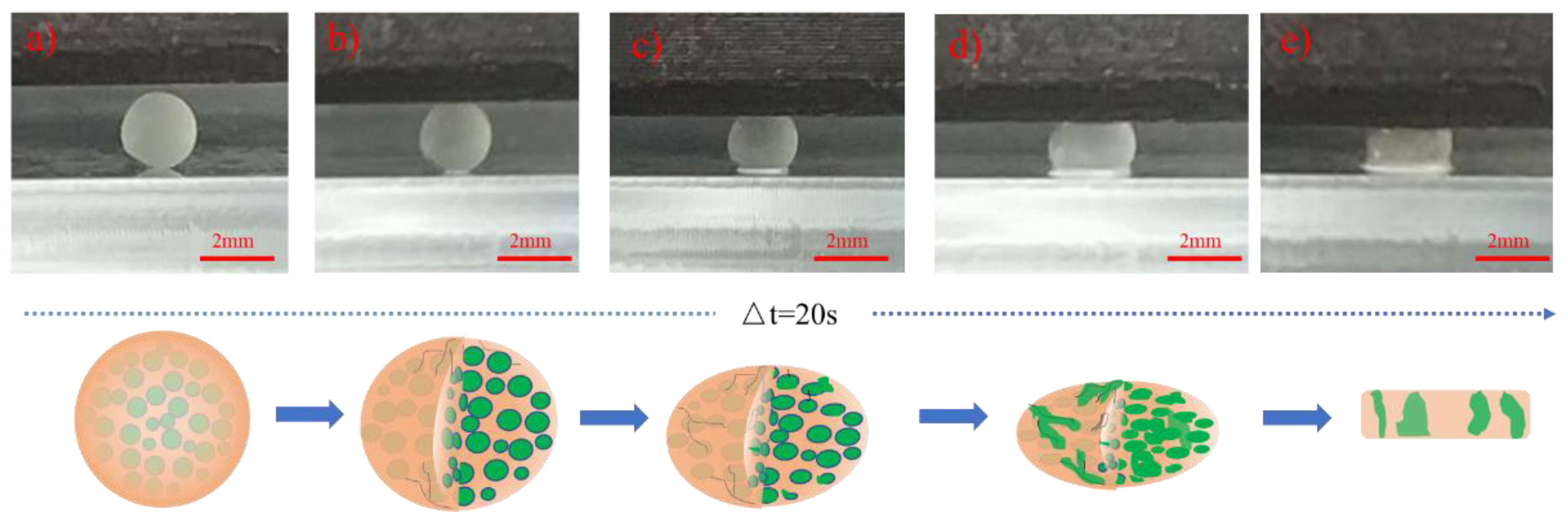
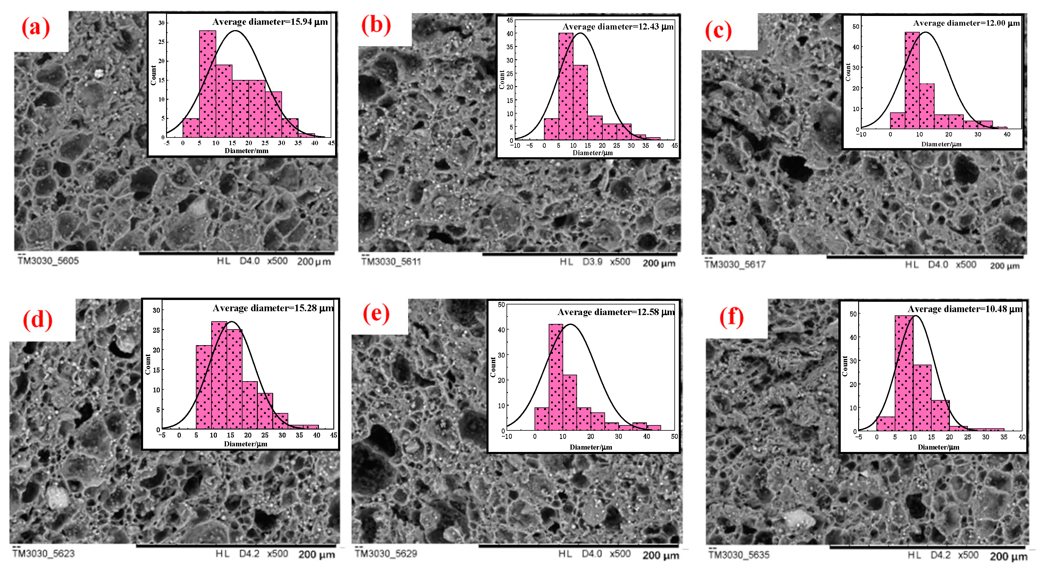
3.4. Effect of Capsule Size on Cavity Distribution
3.5. Slow Release Performance and Diffusion Mechanism
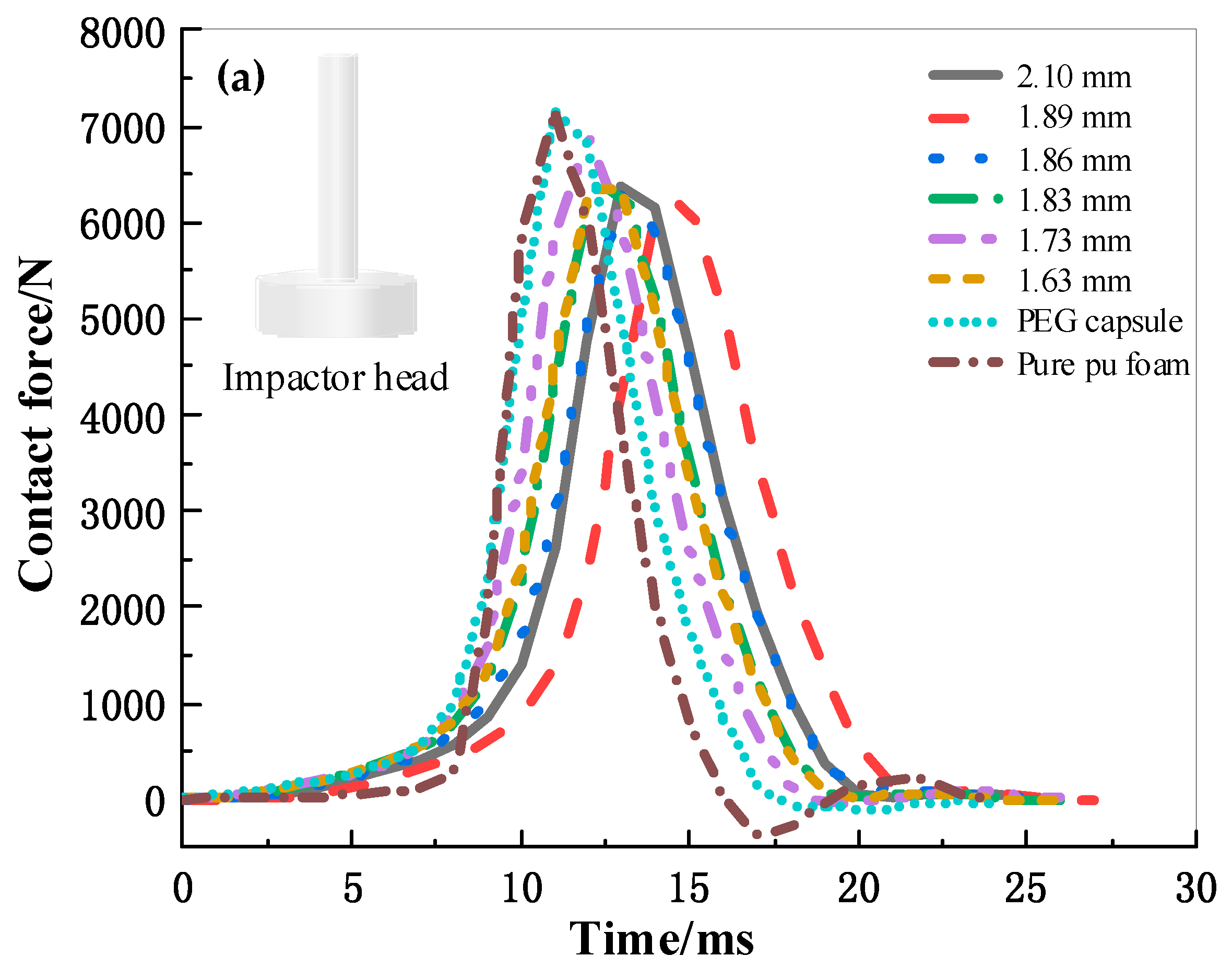
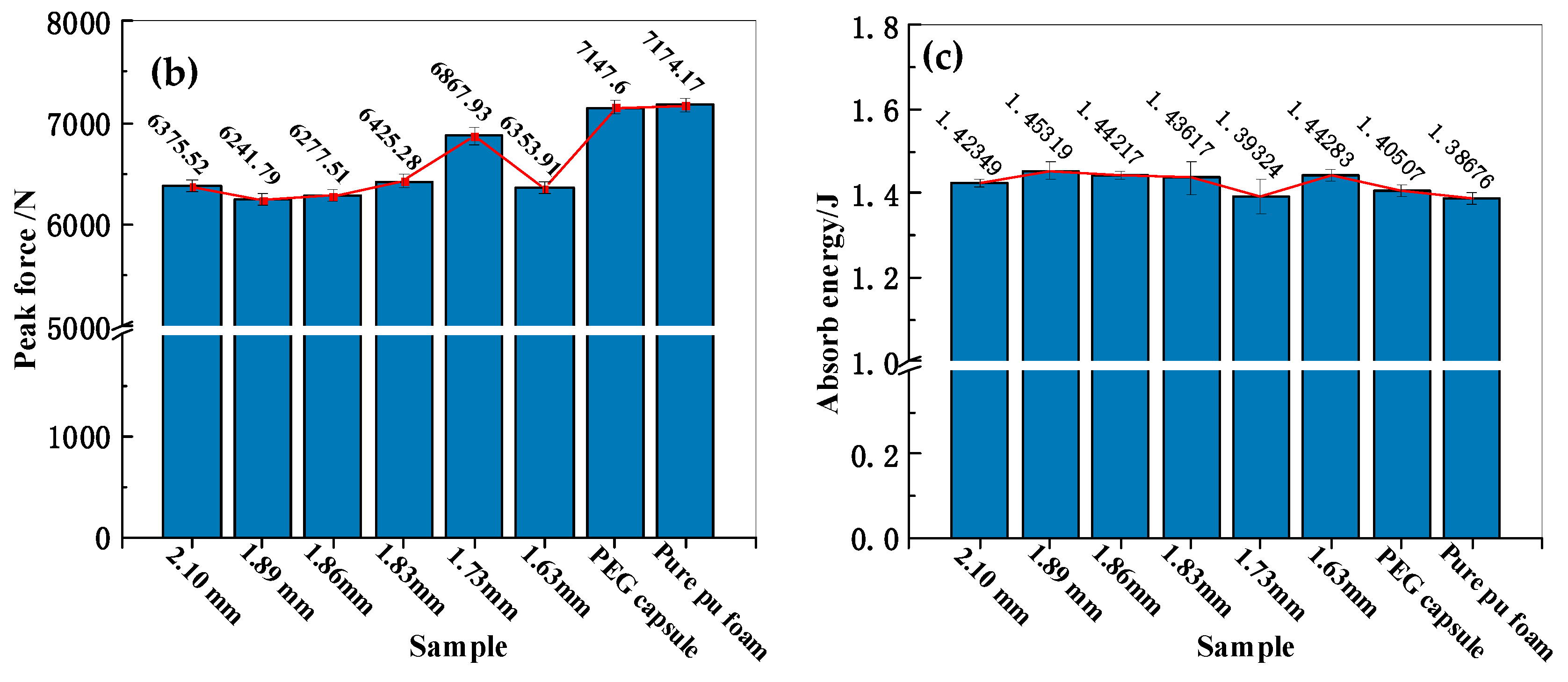
3.6. Effects of Capsule Size on Buffering Performance of Capsule-Filled Foam Composites (CPUC)
4. Conclusions
Author Contributions
Acknowledgments
Conflicts of Interest
Appendix A


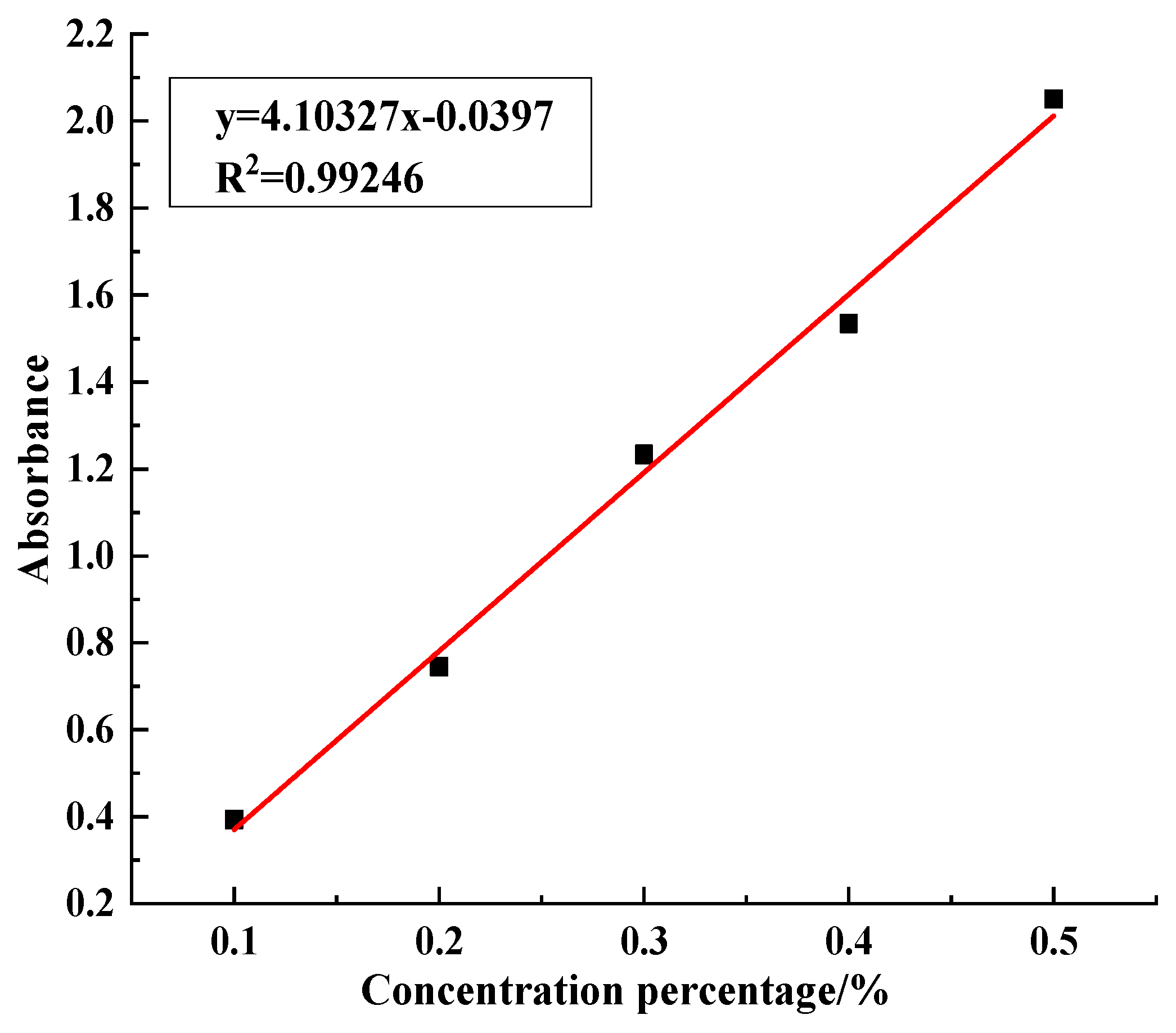
| STF concentration/% | 0.1 | 0.2 | 0.3 | 0.4 | 0.5 |
| Absorbance | 0.393467 | 0.7453 | 1.232833 | 1.5341 | 2.0507 |

References
- Thompson, J.B.; Kindt, J.H.; Drake, B.; Hansma, H.G.; Morse, D.E.; Hansma, P.K. Bone indentation recovery time correlates with bond reforming time. Nature 2001, 414, 773–776. [Google Scholar] [CrossRef] [PubMed]
- Brown, E.; Forman, N.A.; Orellana, C.S.; Zhang, H.; Maynor, B.W.; Betts, D.E.; Desimone, J.M.; Jaeger, H.M. Generality of shear thickening in dense suspensions. Nat. Mater. 2010, 9, 220–224. [Google Scholar] [CrossRef] [PubMed] [Green Version]
- Wagner, N.J.; Brady, J.F. Shear thickening in colloidal dispersions. Phys. Today 2009, 62, 27–32. [Google Scholar] [CrossRef] [Green Version]
- Wen, W.; Huang, X.; Yang, S.; Lu, K.; Sheng, P. The giant electrorheological effect in suspensions of nanoparticles. Nat. Mater. 2003, 2, 727–730. [Google Scholar] [CrossRef] [PubMed]
- Trappe, V.; Prasad, V.; Cipelletti, L.; Segre, P.N.; Weitz, D.A. Jamming phase diagram for attractive particles. Nature 2001, 411, 772–775. [Google Scholar] [CrossRef] [PubMed]
- Dowker, J.S.; Banach, R. Dilatancy in the flow and fracture of stretched colloidal suspensions. Nat. Commun. 2010, 1, 114. [Google Scholar]
- Fu, K.; Wang, H.; Chang, L.; Foley, M.; Friedrich, K.; Ye, L. Low-velocity impact behaviour of a shear thickening fluid (STF) and STF-filled sandwich composite panels. Compos. Sci Technol. 2018, 165, 74–83. [Google Scholar] [CrossRef]
- Majumdar, A.; Laha, A.; Bhattacharjee, D.; Biswas, I. Tuning the structure of 3D woven aramid fabrics reinforced with shear thickening fluid for developing soft body armour. Compos. Struct. 2017, 178, 415–425. [Google Scholar] [CrossRef]
- Thilagavathi, G.; Rajendrakumar, K.; Kannaian, T. Development of textile laminates for improved cut resistance. J. Eng Fibers Fabr. 2010, 5, 40–44. [Google Scholar] [CrossRef]
- Tien, D.T.; Kim, Y.S.; Chung, G.S. Stab resistance of woven and nonwoven aramid fabric composites. Text. Sci. Technol. 2011, 48, 246–251. [Google Scholar]
- Soutrenon, M.; Michaud, V. Impact properties of shear thickening fluid impregnated foams. Smart Mater. Struct. 2014, 23, 1–10. [Google Scholar] [CrossRef]
- Gürgen, S.; Kuşhan, M.C. The stab resistance of fabrics impregnated with shear thickening fluids including various particle size of additives. Compos. Part A Appl. Sci. Manuf. 2017, 94, 50–60. [Google Scholar] [CrossRef]
- Zhang, H.; Zhang, X.; Chen, Q.; Li, X.; Wang, P.; Yang, E.-H.; Duan, F.; Gong, X.; Zhang, Z.; Yang, J. Encapsulation of shear thickening fluid as an easy-to-apply impact-resistant material. J. Mater. Chem. A 2017, 5, 22472–22479. [Google Scholar] [CrossRef]
- Zhang, X.; Zhang, H.; Wang, P.; Chen, Q.; Li, X.; Zhou, Y.; Gong, X.; Zhang, Z.; Yang, E.-H.; Yang, J. Optimization of shear thickening fluid encapsulation technique and dynamic response of encapsulated capsules and polymeric composite. Compos. Sci. Technol. 2019, 170, 165–173. [Google Scholar] [CrossRef]
- Wu, Z.; Zhao, Y.; Kaleem, I.; Li, C. Preparation of calcium-alginate microcapsuled microbial fertilizer coating Klebsiella oxytoca Rs-5 and its performance under salinity stress. Eur. J. Soil Biol. 2011, 47, 152–159. [Google Scholar] [CrossRef]
- Wang, Q.; Du, Y.; Hu, X.; Yang, J.; Fan, L.; Feng, T. Preparation of alginate/soy protein isolate blend fibers through a novel coagulating bath. J. Appl. Polym. Sci. 2010, 101, 425–431. [Google Scholar] [CrossRef]
- Liu, X.; Huo, J.L.; Li, T.T.; Peng, H.K.; Lin, J.H.; Lou, C.W. Investigation of the shear thickening fluid encapsulation in an orifice coagulation bath. Polymers 2019, 11, 519. [Google Scholar] [CrossRef] [PubMed]
- Becker, T.A.; Kipke, D.R.; Brandon, T. Calcium alginate gel: A biocompatible and mechanically stable polymer for endovascular embolization. J. Biomed. Mater. Res. 2015, 54, 76–86. [Google Scholar] [CrossRef]
- George, M.; Abraham, T.E. Polyionic hydrocolloids for the intestinal delivery of protein drugs: Alginate and chitosan—A review. J. Control. Release 2006, 114, 1–14. [Google Scholar] [CrossRef]
- Paques, J.P.; van der Linden, E.; van Rijn, C.J.; Sagis, L.M. Preparation methods of alginate nanoparticles. Adv. Colloid Interface Sci. 2014, 209, 163–171. [Google Scholar] [CrossRef]
- Morelli, S.; Holdich, R.G.; Dragosavac, M.M. Chitosan and poly (vinyl alcohol) microparticles produced by membrane emulsification for encapsulation and pH controlled release. Chem. Eng. J. 2016, 288, 451–460. [Google Scholar] [CrossRef]
- Paques, J.P.; van der Linden, E.; Rijn, C.J.M.V.; Sagis, L.M.C. Alginate submicron beads prepared through w/o emulsification and gelation with CaCl2 nanoparticles. Food Hydrocoll. 2013, 31, 428–434. [Google Scholar] [CrossRef]
- Mørch, Ý.A.; Donati, I.; Strand, B.L. Effect of Ca2+, Ba2+, and Sr2+ on alginate microbeads. Biomacromolecules 2006, 7, 1471–1480. [Google Scholar] [CrossRef] [PubMed]
- Dev, A.; Mohan, J.C.; Sreeja, V.; Tamura, H.; Patzke, G.R.; Hussain, F.; Weyeneth, S.; Nair, S.V.; Jayakumar, R. Novel carboxymethyl chitin nanoparticles for cancer drug delivery applications. Carbohydr. Polym. 2010, 79, 1073–1079. [Google Scholar] [CrossRef]
- Li, D.; Guo, G.; Fan, R.; Liang, J.; Deng, X.; Luo, F.; Qian, Z. PLA/F68/dexamethasone implants prepared by hot-melt extrusion for controlled release of anti-inflammatory drug to implantable medical devices: I. preparation, characterization and hydrolytic degradation study. Int. J. Pharm. 2013, 441, 365–372. [Google Scholar] [CrossRef] [PubMed]
- Tsai, F.-H.; Chiang, P.-Y.; Kitamura, Y.; Kokawa, M.; Islam, M.Z. Producing liquid-core hydrogel beads by reverse spherification: Effect of secondary gelation on physical properties and release characteristics. Food Hydrocoll. 2017, 62, 140–148. [Google Scholar] [CrossRef]
- Hui, M.; Shengyan, P.; Yaqi, H.; Rongxin, Z.; Anatoly, Z.; Wei, C. A highly efficient magnetic chitosan “fluid” adsorbent with a high capacity and fast adsorption kinetics for dyeing wastewater purification. Chem. Eng. J. 2018, 345, 556–565. [Google Scholar] [CrossRef]
- Wang, H.Y.; Li, T.T.; Wu, L.W.; Lou, C.W.; Lin, J.H. Multifunctional, polyurethane-based foam composites reinforced by a fabric structure: Preparation, mechanical, acoustic, and EMI shielding properties. Materials 2018, 11, 2085. [Google Scholar] [CrossRef]
- Thielen, M.; Schmitt, C.N.; Eckert, S.; Speck, T.; Seidel, R. Structure-function relationship of the foam-like pomelo peel (Citrus maxima)—An inspiration for the development of biomimetic damping materials with high energy dissipation. Bioinspir. Biomim. 2013, 8, 025001. [Google Scholar] [CrossRef]
- Zhao, S.; Wang, Y.; Wang, L.; Jin, Y. Preparation, characterization and catalytic application of hierarchically porous LaFeO3 from pomelo peel template. Inorg. Chem. Front. 2017, 4, 994–1002. [Google Scholar] [CrossRef]
- Zhang, X.Z.; Li, W.H.; Gong, X.L. The rheology of shear thickening fluid (STF) and the dynamic performance of an STF-filled damper. Smart Mater. Struct. 2008, 17, 035027. [Google Scholar] [CrossRef]
- Wang, L.; Cheng, X.; Wang, Z.; Huang, H.; Ma, C.; Qin, Y. Effect of the NO + CO reaction on the consumption of carbon supports: An in situ TG-FTIR analysis. Chem. Eng. J. 2018, 352, 90–102. [Google Scholar] [CrossRef]
- Sivakami, R.; Thiyagarajan, P. The effect of citric acid on morphology and photoluminescence properties of white light emitting ZnO-SiO2 nanocomposites. Photonic Nanostruct. 2016, 20, 31–40. [Google Scholar] [CrossRef]
- Cosco, S.; Ambrogi, V.; Musto, P.; Carfagna, C. Properties of poly(urea-formaldheyde) microcapsules containing an epoxy resin. J. Appl. Polym. Sci. 2010, 105, 1400–1411. [Google Scholar] [CrossRef]
- Sarkar, S.; Kim, B. Analysis of graphene-encapsulated polymer microcapsules with superior thermal and storage stability behavior. Polym. Degrad. Stabil. 2017, 138, 72–81. [Google Scholar] [CrossRef]
- Ting, Z.; Min, Z.; Xiao-Mei, T.; Feng, C.; Jian-Hui, Q. Optimal preparation and characterization of poly (urea & ndash; formaldehyde) microcapsules. J. Appl. Polym. Sci. 2010, 115, 2162–2169. [Google Scholar]
- Fei, Y.; Li, Y.; Han, S.; Ma, J. Adsorptive removal of ciprofloxacin by sodium alginate/graphene oxide composite beads from aqueous solution. J. Colloid Interface Sci. 2016, 484, 196–204. [Google Scholar] [CrossRef]
- Zhang, M.; Hong, H.; Lin, H.; Shen, L.; Yu, H.; Ma, G.; Chen, J.; Liao, B.Q. Mechanistic insights into alginate fouling caused by calcium ions based on terahertz time-domain spectra analyses and DFT calculations. Water Res. 2018, 129, 337–346. [Google Scholar] [CrossRef]
- Butt, H.-J.; Cappella, B.; Kappl, M. Force measurements with the atomic force microscope: Technique, interpretation and applications. Surf. Sci. Rep. 2005, 59, 1–152. [Google Scholar] [CrossRef] [Green Version]
- Bellini, C.; Glass, P.; Sitti, M.; Di Martino, E.S. Biaxial mechanical modeling of the small intestine. J. Mech. Behav. Biomed. Mater. 2011, 4, 1727–1740. [Google Scholar] [CrossRef]
- Nechifor, C.-D.; Barzic, A.I.; Stoica, I.; Cloşca, V.; Dorohoi, D.-O. Study on glucose release ability from hydroxypropyl cellulose films. Polym. Bull. 2015, 72, 549–563. [Google Scholar] [CrossRef]
- Liechty, W.B.; Kryscio, D.R.; Slaughter, B.V.; Peppas, N.A. Polymers for drug delivery systems. Annu. Rev. Chem. Biomol. Eng. 2010, 1, 149–173. [Google Scholar] [CrossRef] [PubMed]
- Fabrice, S.M.; Laurent, C.; Jean, Y.C. Mechanical properties of high density polyurethane foams: II effect of the filler size. Compos. Sci. Technol. 2006, 66, 2709–2718. [Google Scholar]


| Capsule Size/mm | TInitial/°C | 1st Tmax /°C | 2nd Tmax /°C | Residual Mass Percentage/% |
|---|---|---|---|---|
| 2.10 | 219.7 | 296.8 | 367.3 | 9.54 |
| 1.89 | 235.4 | 296.3 | 364.7 | 8.67 |
| 1.86 | 224.7 | 295.6 | 367.3 | 9.85 |
| 1.83 | 219.1 | 294.1 | 367.2 | 10.38 |
| 1.73 | 224.3 | 297.0 | 362.4 | 3.28 |
| 1.63 | 232.5 | 295.8 | 362.3 | 7.46 |
| STF | 214.8 | 285.2 | / | 25.77 |
| PEG capsule | 223.5 | 290.1 | 362.4 | 0 |
| Diameter of Capsule/mm | R2 | Release Exponent (n) | Release Kinetic Constant (k) | Release Mechanism |
|---|---|---|---|---|
| 2.10 | 0.902 | 0.202 | 0.069 | Fickian diffusion |
| 1.89 | 0.825 | 0.185 | 0.062 | Fickian diffusion |
| 1.86 | 0.771 | 0.141 | 0.056 | Fickian diffusion |
| 1.83 | 0.774 | 0.289 | 0.063 | Fickian diffusion |
| 1.73 | 0.848 | 0.140 | 0.062 | Fickian diffusion |
| 1.63 | 0.856 | 0.208 | 0.076 | Fickian diffusion |
© 2019 by the authors. Licensee MDPI, Basel, Switzerland. This article is an open access article distributed under the terms and conditions of the Creative Commons Attribution (CC BY) license (http://creativecommons.org/licenses/by/4.0/).
Share and Cite
Li, T.-T.; Huo, J.; Liu, X.; Wang, H.; Shiu, B.-C.; Lou, C.-W.; Lin, J.-H. Characteristics, Compression, and Buffering Performance of Pomelo-Like Hierarchical Capsules Containing Shear Thickening Fluid. Polymers 2019, 11, 1138. https://doi.org/10.3390/polym11071138
Li T-T, Huo J, Liu X, Wang H, Shiu B-C, Lou C-W, Lin J-H. Characteristics, Compression, and Buffering Performance of Pomelo-Like Hierarchical Capsules Containing Shear Thickening Fluid. Polymers. 2019; 11(7):1138. https://doi.org/10.3390/polym11071138
Chicago/Turabian StyleLi, Ting-Ting, Junli Huo, Xing Liu, Hongyang Wang, Bing-Chiuan Shiu, Ching-Wen Lou, and Jia-Horng Lin. 2019. "Characteristics, Compression, and Buffering Performance of Pomelo-Like Hierarchical Capsules Containing Shear Thickening Fluid" Polymers 11, no. 7: 1138. https://doi.org/10.3390/polym11071138