Self-Healing Anti-Atomic-Oxygen Phosphorus-Containing Polyimide Film via Molecular Level Incorporation of Nanocage Trisilanolphenyl POSS: Preparation and Characterization


Abstract
:
1. Introduction
2. Materials and Methods
2.1. Materials
2.2. Measurements
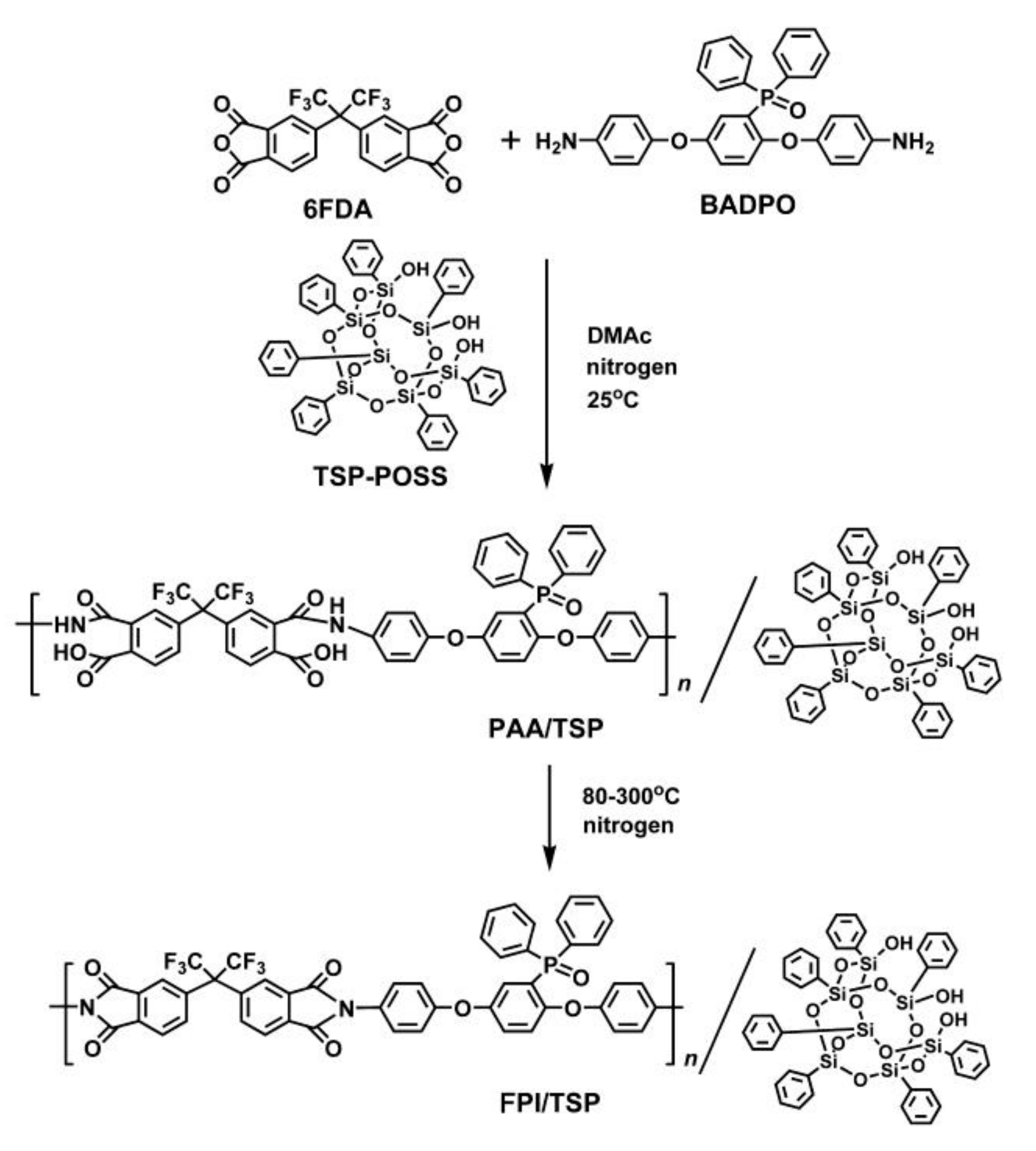
2.3. Synthesis of FPI/TSP–POSS Resins and Preparation of Composite Films
3. Results and Discussion
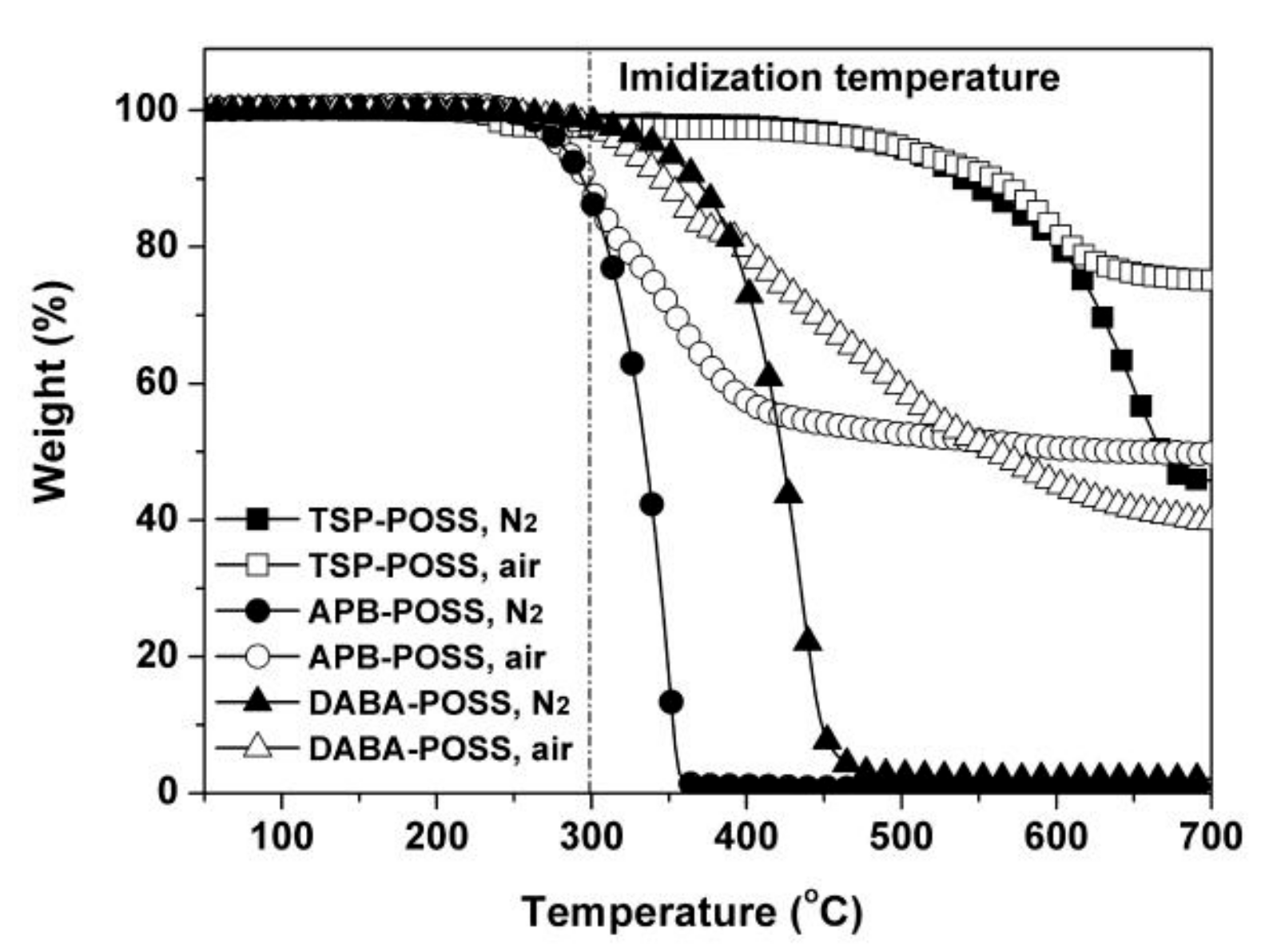
3.1. Evaluation and Choice of POSS Additives for PI Composite Films
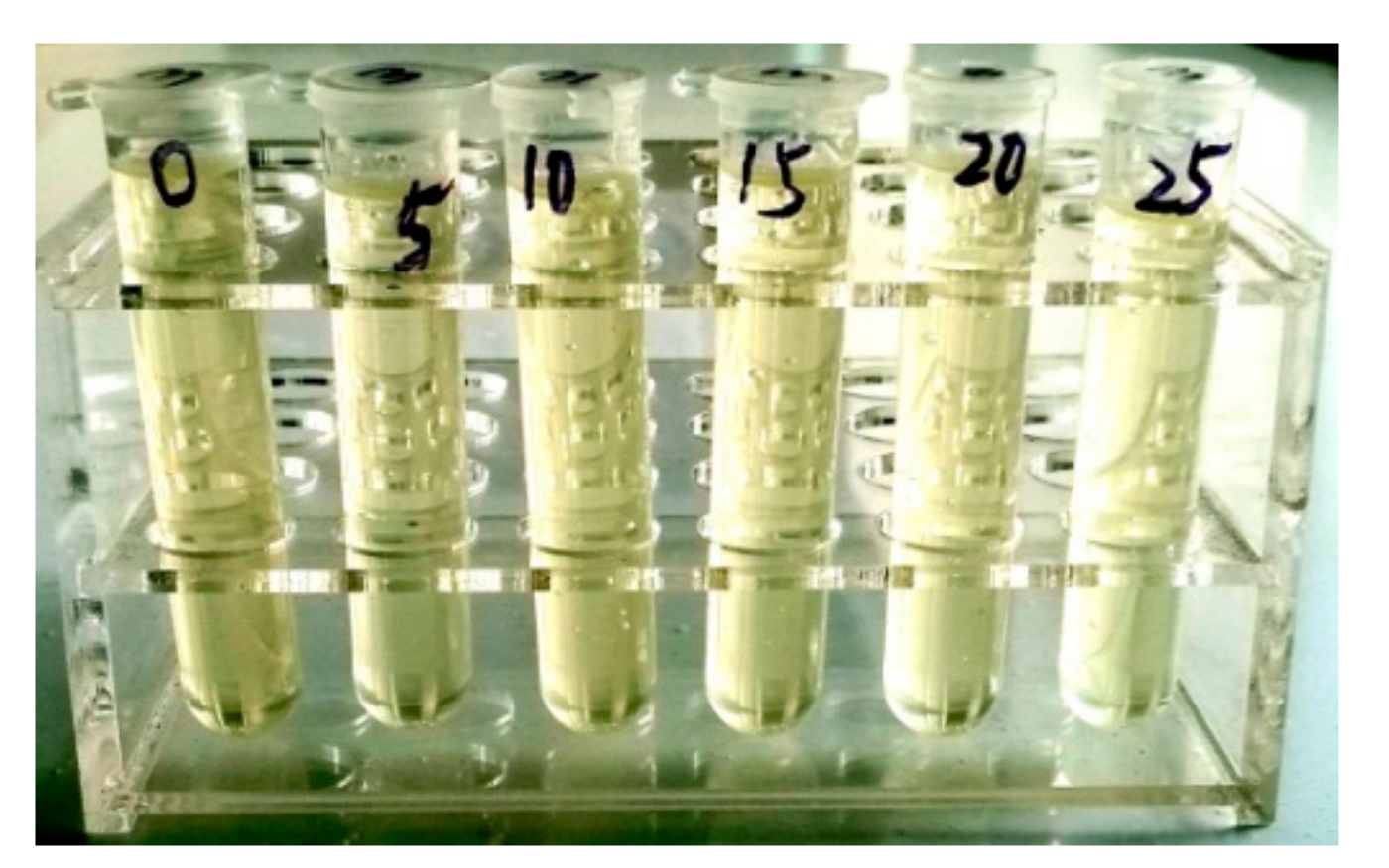
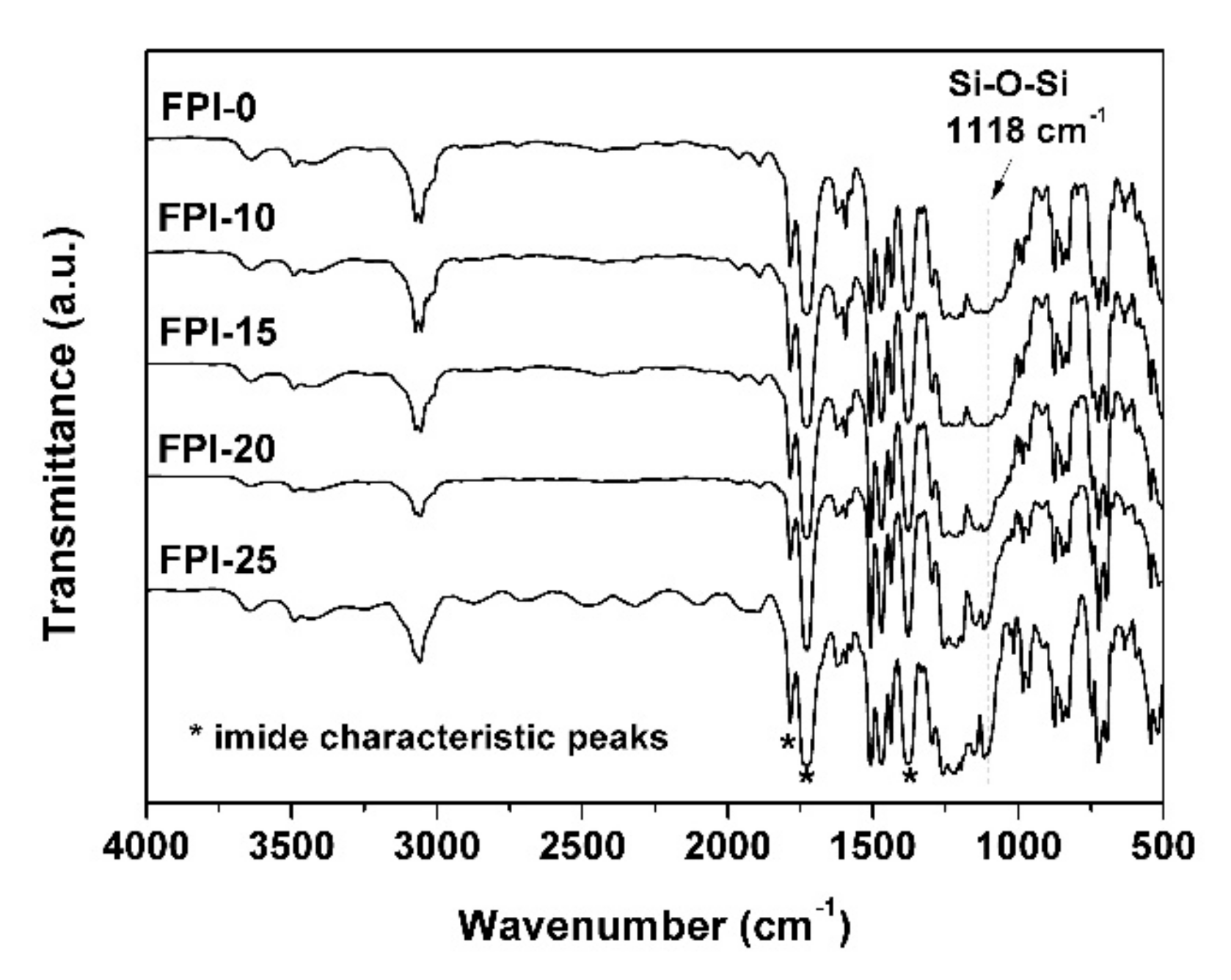
3.2. FPI/TSP–POSS Composite Film Preparation
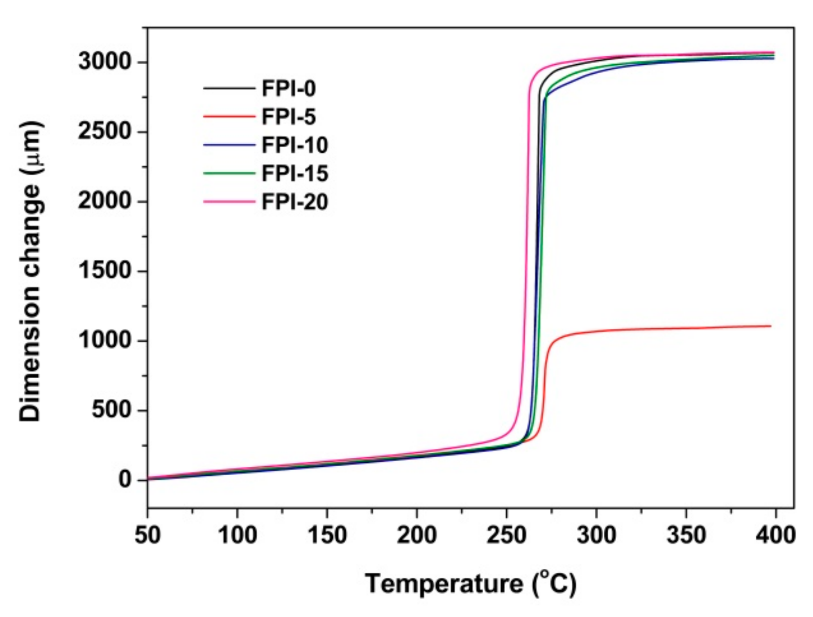
3.3. Thermal Properties
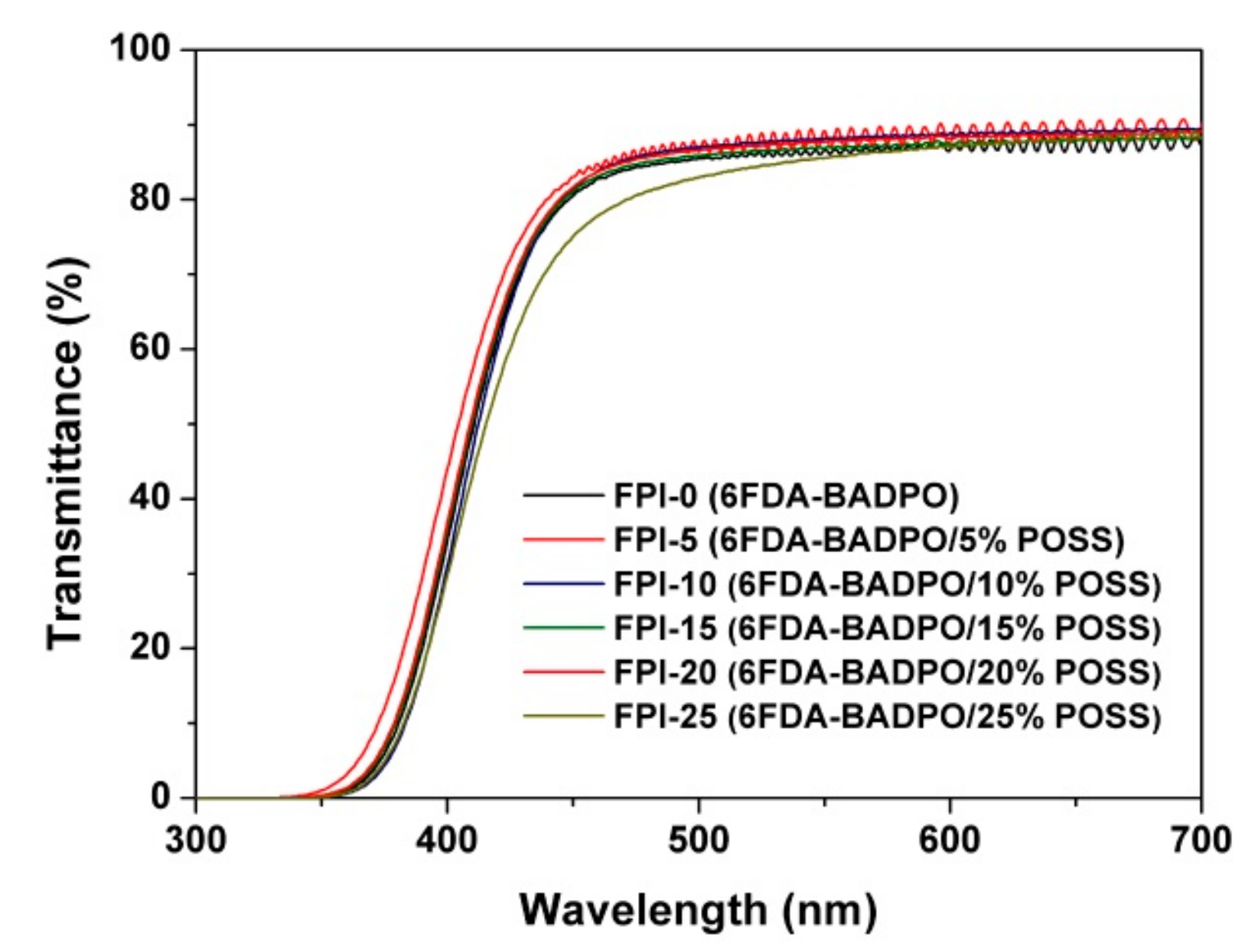
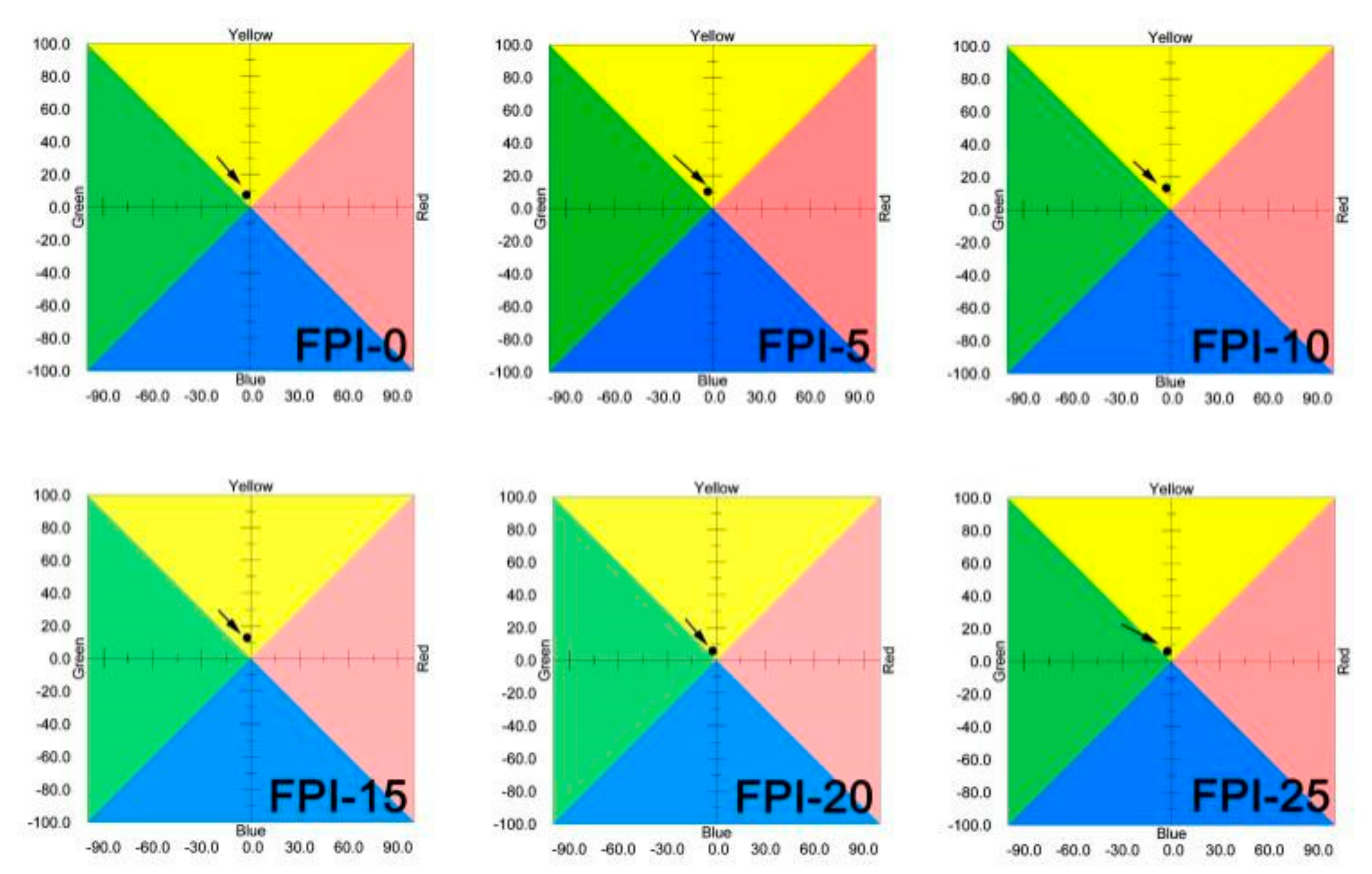
3.4. Optical Properties
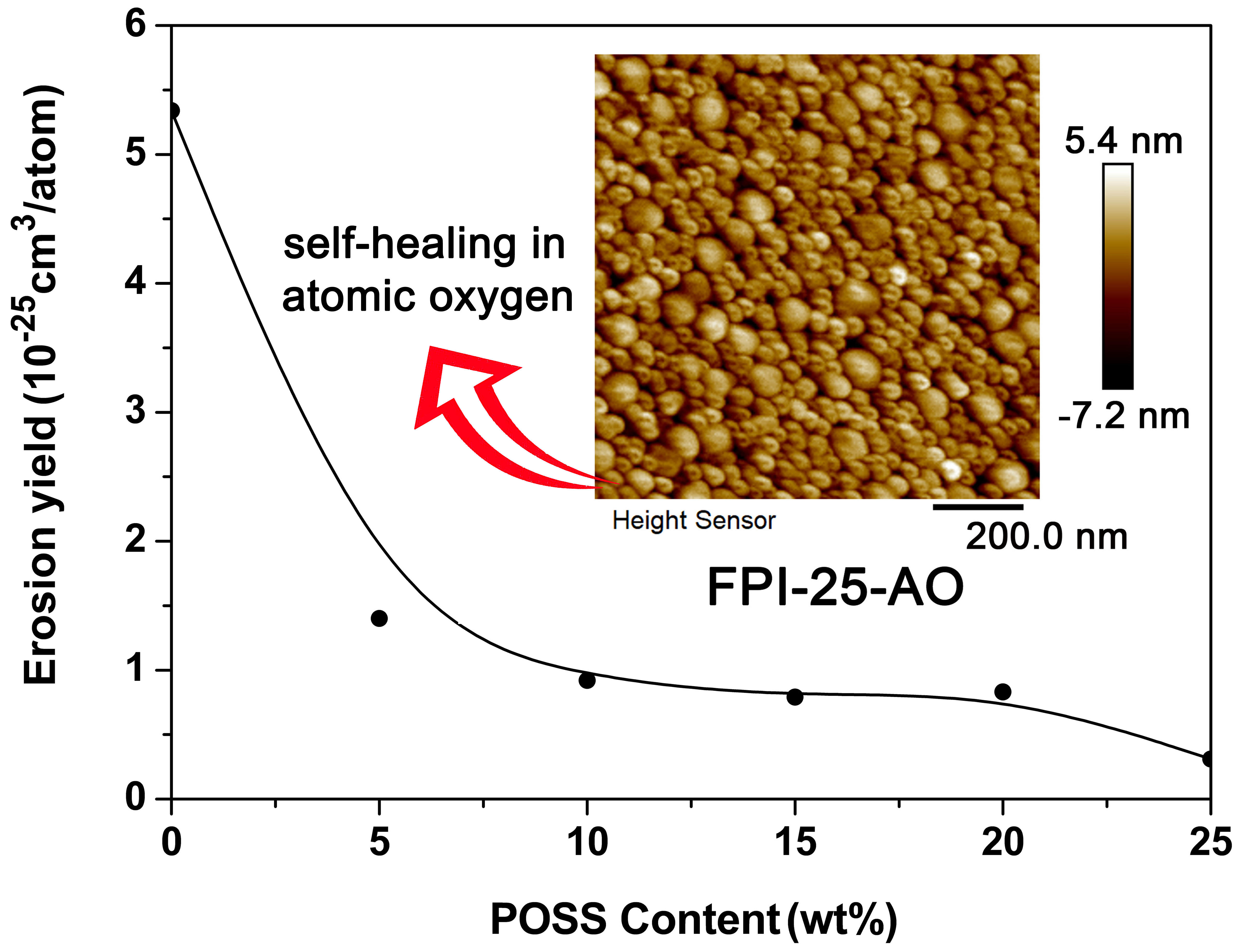
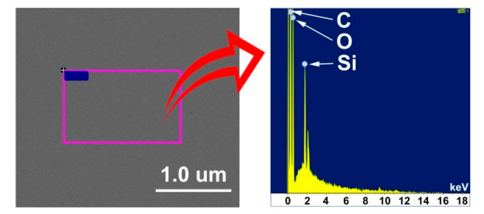
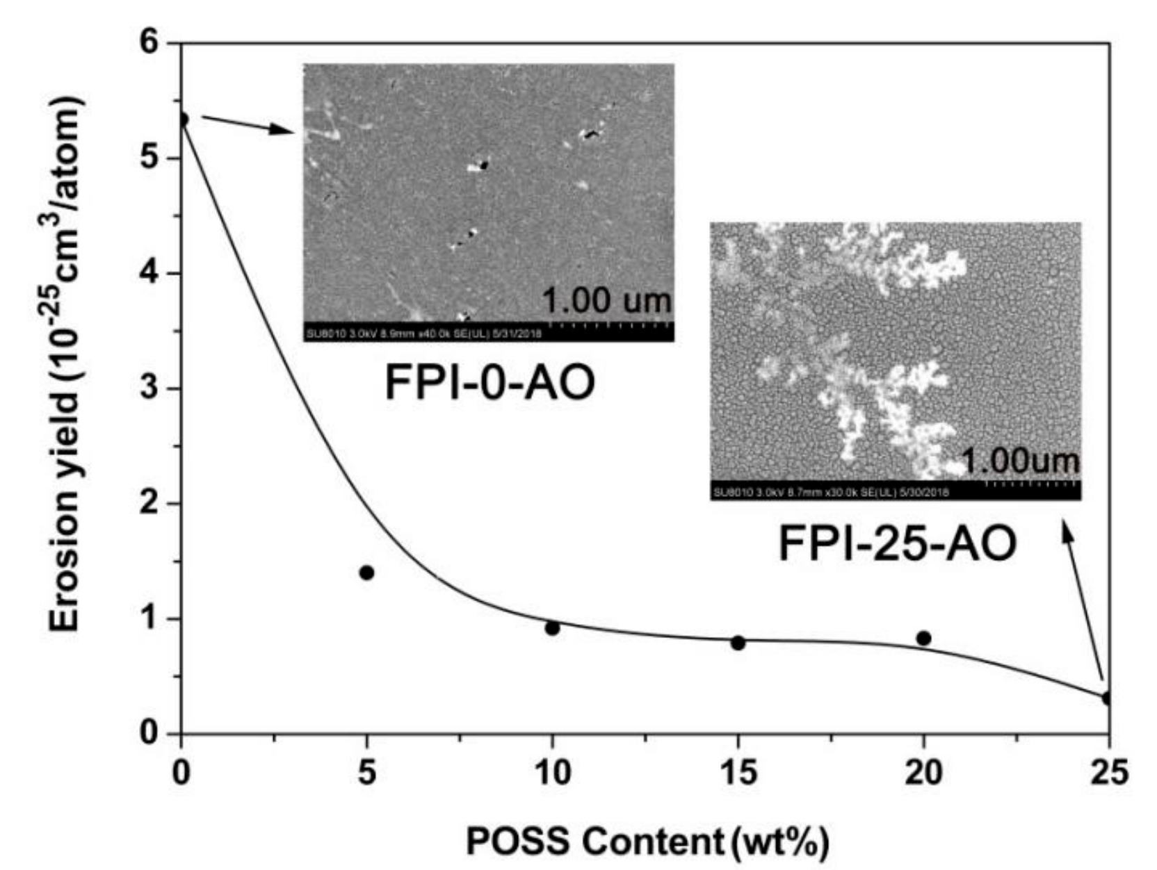
3.5. AO Erosion Properties
4. Conclusions
Author Contributions
Funding
Conflicts of Interest
References
- Reddy, M.R. Effect of low earth orbit atomic oxygen on spacecraft materials. J. Mater. Sci. 1995, 30, 281–307. [Google Scholar] [CrossRef]
- Gouzman, I.; Grossman, E.; Verker, R.; Atar, N.; Bolker, A.; Elia, N. Advances in polyimide-based materials for space applications. Adv. Mater. 2019, 1807738. [Google Scholar] [CrossRef] [PubMed]
- Novikov, L.S.; Chernik, V.N.; Naumov, S.F.; Sokolova, S.P.; Gerasimova, T.I.; Kurilyonok, A.O.; Smirnova, T.N. Degradation testing of spacecraft materials for long flights in low earth orbit. J. Spacecr. Rockets 2006, 43, 534–538. [Google Scholar] [CrossRef]
- Dever, J.A.; Miller, S.K.; Sechkar, E.A.; Wittberg, T.N. Space environment exposure of polymer films on the materials international space station experiment: Results from MISSE 1 and MISSE 2. High Perform. Polym. 2008, 20, 371–387. [Google Scholar] [CrossRef]
- Dever, J.; Banks, B.; de Groh, K.; Miller, S. Degradation of spacecraft materials. In Handbook of Environmental Degradation of Materials, 1st ed.; Kutz, M., Ed.; William Andrew Publishing: New York, NY, USA, 2005; pp. 465–501. [Google Scholar] [Green Version]
- Luo, Y.R. Comprehensive Handbook of Chemical Bond Energies, 1st ed.; Taylor and Francis/CRC: Abingdon, UK, 2007. [Google Scholar]
- Minton, T.K.; Wu, B.; Zhang, J.; Lindholm, N.F.; Abdulagatov, A.I.; O’Patchen, J.; George, S.M.; Groner, M.D. Protecting polymers in space with atomic layer deposition coatings. ACS Appl. Mater. Interfaces 2010, 2, 2515–2520. [Google Scholar] [CrossRef] [PubMed]
- Tagawa, M.; Yokota, K.; Ohmae, N.; Kinoshita, H. Volume diffusion of atomic oxygen in α-SiO2 protective coating. High Perform. Polym. 2000, 12, 53–63. [Google Scholar] [CrossRef]
- Qian, M.; Murray, V.J.; Wei, W.; Marshall, B.C.; Minton, T.K. Resistance of POSS polyimide blends to hyperthermal atomic oxygen attack. ACS Appl. Mater. Interfaces 2016, 8, 33982–33992. [Google Scholar] [CrossRef] [PubMed]
- Wang, X.; Li, Y.; Qian, Y.; Qi, H.; Li, J.; Sun, J. Mechanically robust atomic oxygen-resistant coatings capable of autonomously healing damage in low earth orbit space environment. Adv. Mater. 2018, 30, 1803854. [Google Scholar] [CrossRef] [PubMed]
- Lei, X.F.; Chen, Y.; Zhang, H.P.; Li, X.J.; Yao, P.; Zhang, Q.Y. Space survivable polyimides with excellent optical transparency and self-healing properties derived from hyperbranched polysiloxane. ACS Appl. Mater. Interfaces 2013, 5, 10207–10220. [Google Scholar] [CrossRef]
- Li, X.; Al-Ostaz, A.; Jaradat, M.; Rahmani, F.; Nouranian, S.; Rushing, G.; Manasrah, A.; Alkhateb, H.; Finckenor, M.; Lichtenhan, J. Substantially enhanced durability of polyhedral oligomeric silsequioxane-polyimide nanocomposites against atomic oxygen erosion. Eur. Polym. J. 2017, 92, 233–249. [Google Scholar] [CrossRef]
- García, S.J.; Fischer, H.R.; Van Der, Z.S. A critical appraisal of the potential of self healing polymeric coatings. Prog. Org. Coat. 2011, 72, 211–221. [Google Scholar] [CrossRef]
- Lei, X.; Qiao, M.; Tian, L.; Chen, Y.; Zhang, Q. Evolution of surface chemistry and morphology of hyperbranched polysiloxane polyimides in simulated atomic oxygen environment. Corros. Sci. 2015, 98, 560–572. [Google Scholar] [CrossRef]
- Connell, J.W. The effect of low earth orbit atomic oxygen exposure on phenylphosphine oxide-containing polymers. High Perform. Polym. 2000, 12, 43–52. [Google Scholar] [CrossRef]
- Wang, X.; Zhao, X.; Wang, M.; Shen, Z. The effects of atomic oxygen on polyimide resin matrix composite containing nano-silicon dioxide. Nucl. Instrum. Meth. B 2006, 243, 320–324. [Google Scholar] [CrossRef]
- Xiao, F.; Wang, K.; Zhan, M. Atomic oxygen erosion resistance of polyimide/ZrO2 hybrid films. Appl. Surf. Sci. 2010, 256, 7384–7388. [Google Scholar] [CrossRef]
- Philips, S.H.; Gonzalez, R.I.; Chaffee, K.P.; Haddad, T.S.; Hoflund, G.B.; Hsiao, B.S.; Fu, B.X. Remarkable AO resistance of POSS inorganic/organic polymers. In Proceedings of the 45th International SAMPE Symposium and Exhibition, Long Beach, CA, USA, 21–25 May 2000. [Google Scholar]
- Shepp, A.; Haghighat, R.; Lennhoff, J.; Schuler, P.; Connell, J.; Vaughn, J.; Swiener, J.J. Tor and cor- AO-VUV resistant polymers for space. In Protection of Materials and Structures from the Low Earth Orbit Space Environment, Proceedings of ICPMSE-3, Third International Space Conference, Toronto, ON, Canada, 26–26 April 1996; Springer: Dordrecht, The Netherlands, 1999. [Google Scholar]
- Zhao, Y.; Gao, H.; Li, G.M.; Liu, F.F.; Dai, X.M.; Dong, Z.X.; Qiu, X.P. Synthesis and AO resistant properties of novel polyimide fibers containing phenylphosphine oxide groups in main chain. Chin. J. Polym. Sci. 2019, 37, 59–67. [Google Scholar] [CrossRef]
- Li, G.; Wang, L.; Ni, H.; Pittman, C.U. Polyhedral oligomeric silsesquioxane (POSS) polymers and copolymers: A review. J. Inorg. Organomet. Polym. 2001, 11, 123–154. [Google Scholar] [CrossRef]
- Blanco, I. The rediscovery of POSS: A molecule rather than a filler. Polymers 2018, 10, 904. [Google Scholar] [CrossRef] [PubMed]
- Kuo, S.W.; Chang, F.C. POSS related polymer nanocomposites. Prog. Polym. Sci. 2011, 36, 1649–1696. [Google Scholar] [CrossRef]
- Yang, B.; Xu, H.; Yang, Z.; Liu, X. Design and architecture of low-dielectric-constant organic–inorganic hybrids from octahydridosilsesquioxanes. J. Mater. Chem. 2009, 19, 9038–9044. [Google Scholar] [CrossRef]
- Phillips, S.H.; Haddad, T.S.; Tomczak, S.J. Developments in nanoscience: Polyhedral oligomeric silsesquioxane (POSS)-polymers. Curr. Opin. Solid State Mater. Sci. 2004, 8, 21–29. [Google Scholar] [CrossRef]
- Suliga, A.; Jakubczyk, E.M.; Hamerton, I.; Viquerat, A. Analysis of atomic oxygen and ultraviolet exposure effects on cycloaliphatic epoxy resins reinforced with octa-functional POSS. Acta Astronaut. 2018, 142, 103–111. [Google Scholar] [CrossRef] [Green Version]
- Liu, L.R.; Huang, Y.D.; Liu, L. Effects of TriSilanolIsobutyl-POSS on thermal stability of methylsilicone resin. Polym. Degrad. Stab. 2006, 91, 2731–2738. [Google Scholar] [CrossRef]
- Liang, K.; Li, G.; Toghiani, H.; Koo, J.H.; Pittman, C.U. Cyanate ester/polyhedral oligomeric silsesquioxane (POSS) nanocomposites: Synthesis and characterization. Chem. Mater. 2006, 18, 301–312. [Google Scholar] [CrossRef]
- Liu, Y.Z.; Sun, Y.; Zeng, F.L.; Zhang, Q.H.; Geng, L. Characterization and analysis on atomic oxygen resistance of POSS/PVDF composites. Appl. Surf. Sci. 2014, 320, 908–913. [Google Scholar] [CrossRef]
- Mohamed, M.; Kuo, S. Functional polyimide/polyhedral oligomeric silsesquioxane nanocomposites. Polymers 2019, 11, 26. [Google Scholar] [CrossRef] [PubMed]
- Wang, P.; Tang, Y.; Yu, Z.; Gu, J.; Kong, J. Advanced aromatic polymers with excellent antiatomic oxygen performance derived from molecular precursor strategy and copolymerization of polyhedral oligomeric silsesquioxane. ACS Appl. Mater. Interfaces 2015, 7, 20144–20155. [Google Scholar] [CrossRef] [PubMed]
- Lee, Y.J.; Kuo, S.W.; Huang, C.F.; Chang, F.C. Synthesis and characterization of polybenzoxazine networks nanocomposites containing multifunctional polyhedral oligomeric silsesquioxane (POSS). Polymer 2006, 47, 4378–4386. [Google Scholar] [CrossRef]
- Verker, R.; Grossman, E.; Eliaz, N. Erosion of POSS-polyimide films under hypervelocity impact and atomic oxygen: The role of mechanical properties at elevated temperatures. Acta Mater. 2009, 57, 1112–1119. [Google Scholar] [CrossRef]
- Liu, F.; Guo, H.; Zhao, Y.; Qiu, X.; Gao, L. Enhanced resistance to the atomic oxygen exposure of POSS/polyimide composite fibers with surface enrichment through wet spinning. Eur. Polym. J. 2018, 105, 115–125. [Google Scholar] [CrossRef]
- Verker, R.; Grossman, E.; Gouzman, I.; Eliaz, N. TriSilanolPhenyl POSS–polyimide nanocomposites: Structure–properties relationship. Compos. Sci. Technol. 2009, 69, 2178–2184. [Google Scholar] [CrossRef]
- Fang, G.; Li, H.; Liu, J.; Ni, H.; Yang, H.; Yang, S. Intrinsically atomic-oxygen-resistant POSS-containing polyimide aerogels: Synthesis and characterization. Chem. Lett. 2015, 44, 1083–1085. [Google Scholar] [CrossRef]
- Minton, T.K.; Wright, M.E.; Tomczak, S.J.; Marquez, S.A.; Shen, L.; Brunsvold, A.L.; Cooper, R.; Zhang, J.M.; Vij, V.; Guenthner, A.J.; et al. Atomic oxygen effects on POSS polyimides in low earth orbit. ACS Appl. Mater. Interfaces 2012, 4, 492–502. [Google Scholar] [CrossRef] [PubMed]
- Reddy, M.R.; Srinivasamurthy, N.; Agrawal, B.L. Atomic oxygen protective coatings for Kapton film: A review. Surf. Coat. Technol. 1993, 58, 1–17. [Google Scholar] [CrossRef]
- Li, Z.; Song, H.; He, M.; Liu, J.; Yang, S. Atomic oxygen-resistant and transparent polyimide coatings from [3,5-bis (3-aminophenoxy) phenyl] diphenylphosphine oxide and aromatic dianhydrides: Preparation and characterization. Prog. Org. Coat. 2012, 75, 49–58. [Google Scholar] [CrossRef]
- Cuthbertson, J.W.; Molley, R.W.; Langer, W.D. High-flux source of low-energy neutral beams using reflection of ions from metals. Rev. Sci. Instrum. 1992, 63, 5279–5288. [Google Scholar] [CrossRef]
- De Groh, K.K.; Banks, B.A.; Mccarthy, C.E. MISSE 2 PEACE polymers atomic oxygen erosion experiment on the international space station. High Perform. Polym. 2008, 20, 388–409. [Google Scholar] [CrossRef]
- Atar, N.; Grossman, E.; Gouzman, I.; Bolker, A.; Murray, V.J.; Marshall, B.C.; Qian, M.; Minton, T.K.; Hanein, Y. Atomic-oxygen-durable and electrically-conductive CNT-POSS-polyimide flexible films for space applications. ACS Appl. Mater. Interfaces 2015, 7, 12047–12056. [Google Scholar] [CrossRef]
- Blanco, I.; Abate, L.; Bottino, F.A. Mono substituted octaphenyl POSSs: The effects of substituents on thermal properties and solubility. Thermochim. Acta 2017, 655, 117–123. [Google Scholar] [CrossRef]
- Blanco, I.; Bottino, F.A.; Abate, L. Influence of n-alkyl substituents on the thermal behaviour of Polyhedral Oligomeric Silsesquioxanes (POSSs) with different cage’s periphery. Thermochim. Acta 2016, 623, 50–57. [Google Scholar] [CrossRef]
- Blanco, I.; Bottino, F.A.; Cicala, G.; Cozzo, G.; Latteri, A.; Recca, A. Synthesis and thermal characterization of new dumbbell shaped POSS/PS nanocomposites: Influence of the symmetrical structure of the nanoparticles on the dispersion/aggregation in the polymer matrix. Polym. Compos. 2015, 36, 1394–1400. [Google Scholar] [CrossRef]
- Zhang, Y.; Liu, J.; Wu, X.; Guo, C.; Qu, L.; Zhang, X. Trisilanolphenyl-POSS nano-hybrid poly (biphenyl dianhydride-p-phenylenediamine) polyimide composite films: Miscibility and structure-property relationship. J. Polym. Res. 2018, 25, 139. [Google Scholar] [CrossRef]
- Liu, J.; Ueda, M. High refractive index polymers: Fundamental research and practical applications. J. Mater. Chem. 2009, 19, 8907–8919. [Google Scholar] [CrossRef]
- Sarkar, B.; Ayandele, E.; Venugopal, V.; Alexandridis, P. Polyhedral oligosilsesquioxane (POSS) nanoparticle localization in ordered structures formed by solvated block copolymers. Macromol. Chem. Phys. 2013, 214, 2716–2724. [Google Scholar] [CrossRef]


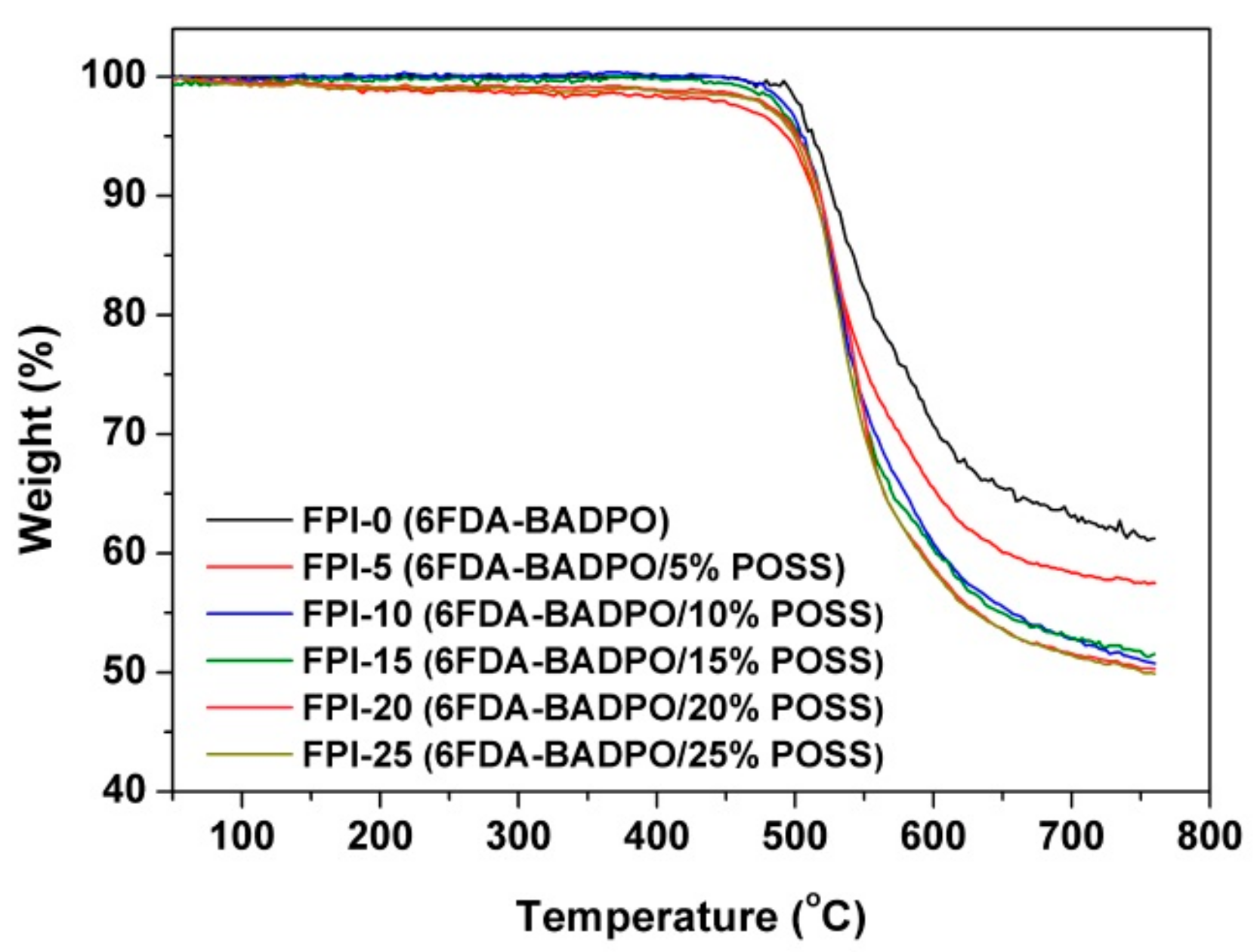
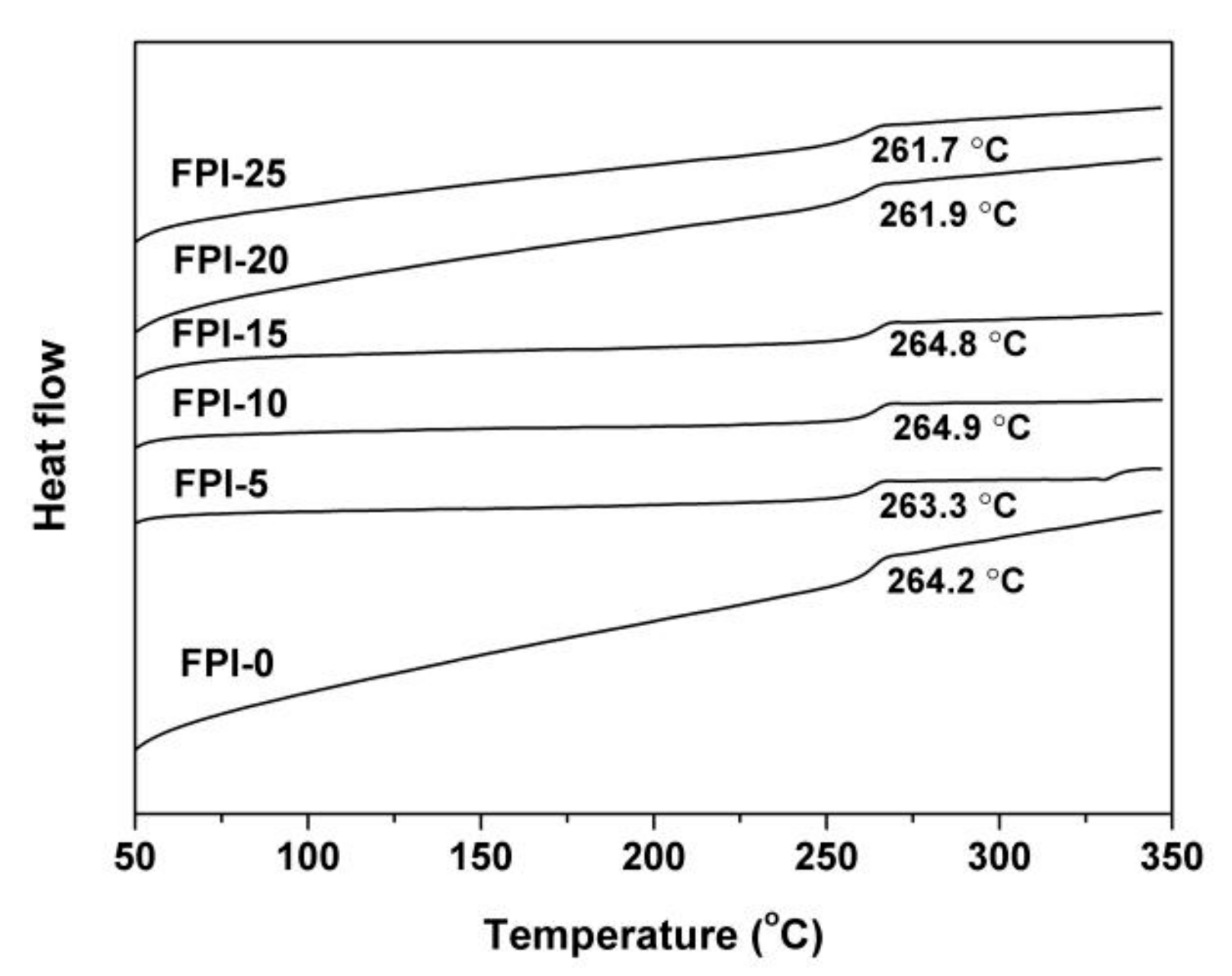
| Samples | Tg1 (°C) | T5%1 (°C) | T10%1 (°C) | Rw7601 (%) | CTE 1 (10−6/K) |
|---|---|---|---|---|---|
| FPI-0 | 264.2 | 514 | 527 | 61.2 | 66.6 |
| FPI-5 | 263.3 | 492 | 514 | 57.5 | 71.1 |
| FPI-10 | 264.9 | 504 | 517 | 50.7 | 65.2 |
| FPI-15 | 264.8 | 507 | 520 | 50.1 | 69.5 |
| FPI-20 | 261.9 | 501 | 517 | 50.3 | 75.2 |
| FPI-25 | 261.7 | 500 | 515 | 50.0 | 76.3 |
| Samples | λcutoff1 (nm) | T4502 (%) | T450AO2 (%) | b* 3 | Haze (%) | n4 | |||
|---|---|---|---|---|---|---|---|---|---|
| nTE | nTM | nAV | Δn | ||||||
| FPI-0 | 340.5 | 80.5 | 5.9 | 7.53 | 0.72 | 1.6230 | 1.6227 | 1.6229 | 0.0003 |
| FPI-5 | 333.0 | 83.0 | 39.7 | 10.23 | 11.56 | 1.6338 | 1.6256 | 1.6311 | 0.0082 |
| FPI-10 | 344.5 | 81.5 | 47.0 | 13.28 | 6.76 | 1.6267 | 1.6173 | 1.6236 | 0.0094 |
| FPI-15 | 339.5 | 81.1 | 45.0 | 12.70 | 6.74 | 1.6275 | 1.6289 | 1.6234 | 0.0086 |
| FPI-20 | 337.0 | 81.7 | 40.0 | 6.17 | 4.49 | 1.6189 | 1.6126 | 1.6168 | 0.0063 |
| FPI-25 | 344.5 | 75.1 | 58.9 | 5.71 | 3.28 | 1.6182 | 1.6100 | 1.6155 | 0.0082 |
| Samples | TSP–POSS 1 (%) | W12 (mg) | W22 (mg) | ΔW 3 (mg) | Es4 (10−25 cm3/atom) |
|---|---|---|---|---|---|
| FPI-0 | 0 | 13.35 | 12.13 | 1.22 | 5.34 |
| FPI-5 | 5 | 11.14 | 10.82 | 0.32 | 1.40 |
| FPI-10 | 10 | 15.37 | 15.16 | 0.21 | 0.92 |
| FPI-15 | 15 | 13.52 | 13.34 | 0.18 | 0.79 |
| FPI-20 | 20 | 17.87 | 17.68 | 0.19 | 0.83 |
| FPI-25 | 25 | 17.63 | 17.56 | 0.07 | 0.31 |
| Kapton | - | 30.85 | 24.00 | 6.85 | 30.00 |
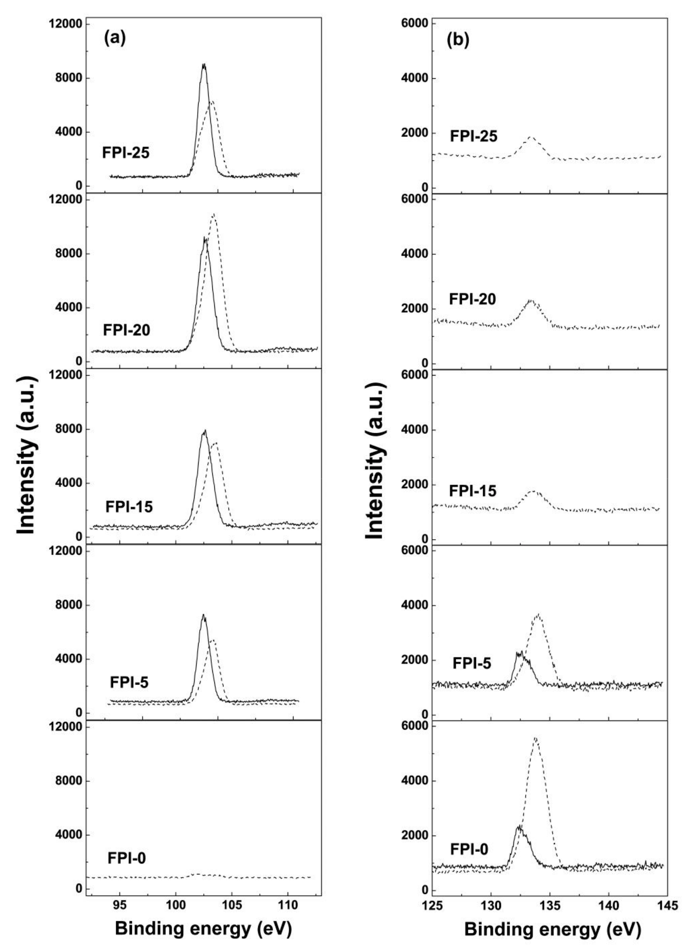
| Samples | Relative Atomic Concentration (%) | |||||||||
|---|---|---|---|---|---|---|---|---|---|---|
| Unexposed Samples | AO Exposed Samples | |||||||||
| Si2p | P2p | C1s | O1s | F1s | Si2p | P2p | C1s | O1s | F1s | |
| FPI-0 | ND 1 | 0.79 | 72.04 | 14.52 | 4.79 | ND | 5.64 | 32.31 | 28.20 | 5.77 |
| FPI-5 | 4.71 | 0.56 | 67.48 | 17.71 | 3.13 | 7.87 | 3.32 | 31.41 | 31.57 | 3.20 |
| FPI-15 | 5.34 | ND | 67.69 | 20.62 | 1.88 | 12.04 | 0.93 | 37.53 | 32.03 | 0.80 |
| FPI-20 | 6.80 | ND | 65.81 | 22.07 | 0.48 | 14.63 | 0.95 | 30.70 | 35.98 | 0.62 |
| FPI-25 | 7.19 | ND | 76.16 | 15.66 | 0.29 | 15.36 | 0.87 | 30.04 | 36.94 | 0.58 |
© 2019 by the authors. Licensee MDPI, Basel, Switzerland. This article is an open access article distributed under the terms and conditions of the Creative Commons Attribution (CC BY) license (http://creativecommons.org/licenses/by/4.0/).
Share and Cite
Wu, B.; Zhang, Y.; Yang, D.; Yang, Y.; Yu, Q.; Che, L.; Liu, J. Self-Healing Anti-Atomic-Oxygen Phosphorus-Containing Polyimide Film via Molecular Level Incorporation of Nanocage Trisilanolphenyl POSS: Preparation and Characterization. Polymers 2019, 11, 1013. https://doi.org/10.3390/polym11061013
Wu B, Zhang Y, Yang D, Yang Y, Yu Q, Che L, Liu J. Self-Healing Anti-Atomic-Oxygen Phosphorus-Containing Polyimide Film via Molecular Level Incorporation of Nanocage Trisilanolphenyl POSS: Preparation and Characterization. Polymers. 2019; 11(6):1013. https://doi.org/10.3390/polym11061013
Chicago/Turabian StyleWu, Bohan, Yan Zhang, Dayong Yang, Yanbin Yang, Qiang Yu, Li Che, and Jingang Liu. 2019. "Self-Healing Anti-Atomic-Oxygen Phosphorus-Containing Polyimide Film via Molecular Level Incorporation of Nanocage Trisilanolphenyl POSS: Preparation and Characterization" Polymers 11, no. 6: 1013. https://doi.org/10.3390/polym11061013