Modified Carbon Fiber Paper-Based Electrodes Wrapped by Conducting Polymers with Enhanced Electrochemical Performance for Supercapacitors


Abstract
:
1. Introduction
2. Experimental
2.1. Materials
2.2. Preparation of Activated Carbon Fiber Paper
2.3. Preparation of Cellulose Nanofibers
2.4. Preparation of A-CFP Based Electrodes
2.5. Assemble of the Symmetric Supercapacitors (ASSC)
2.6. Chemical Characterization and Electrochemical Measurements
3. Results and Discussion
3.1. SEM Images
3.2. FTIR Analysis
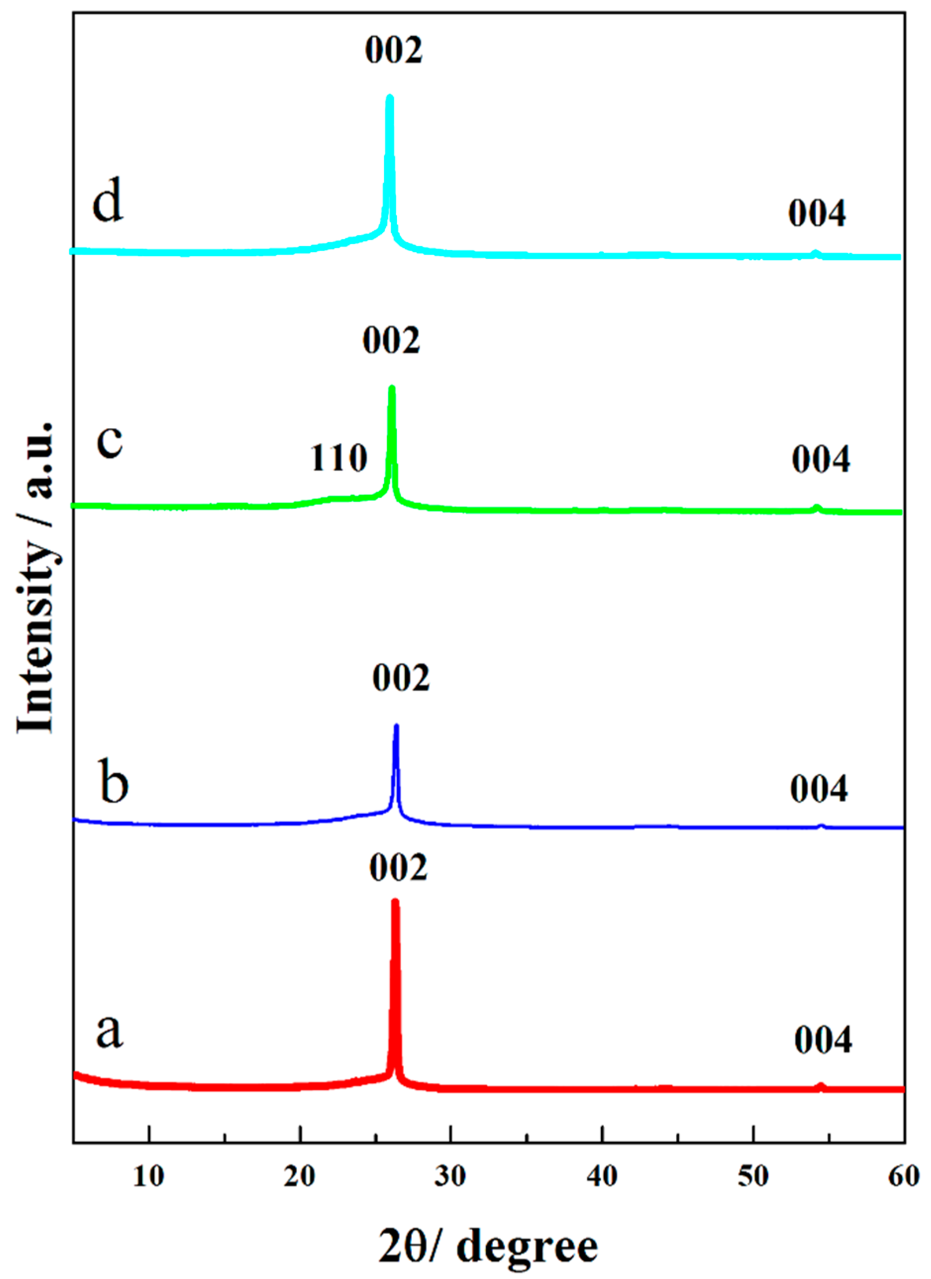
3.3. XRD Analysis
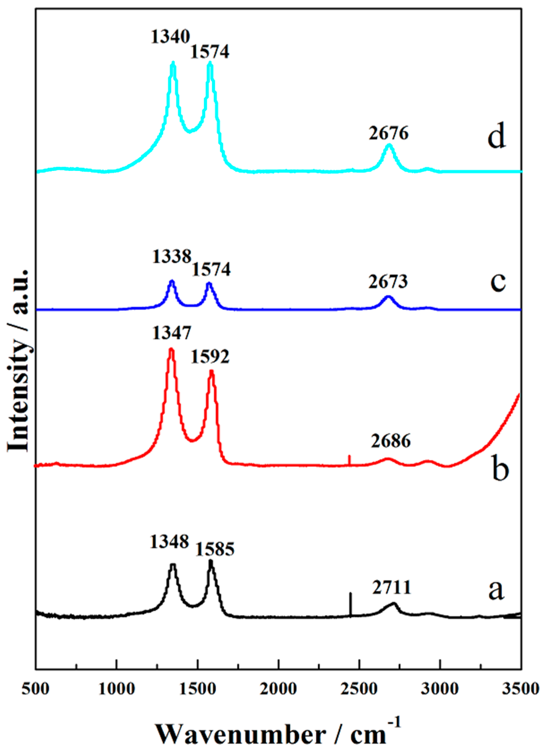
3.4. Raman Analysis
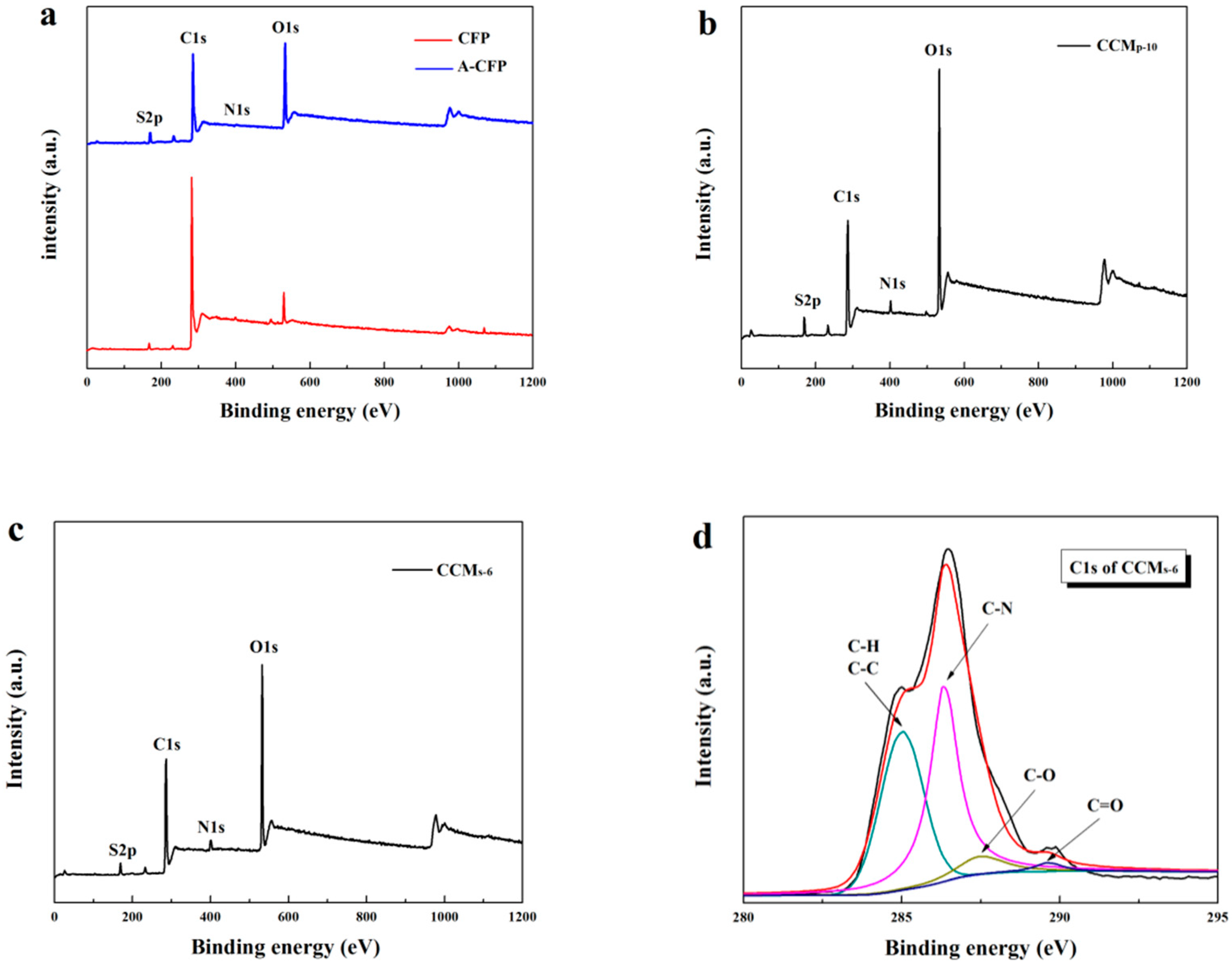
3.5. XPS Analysis
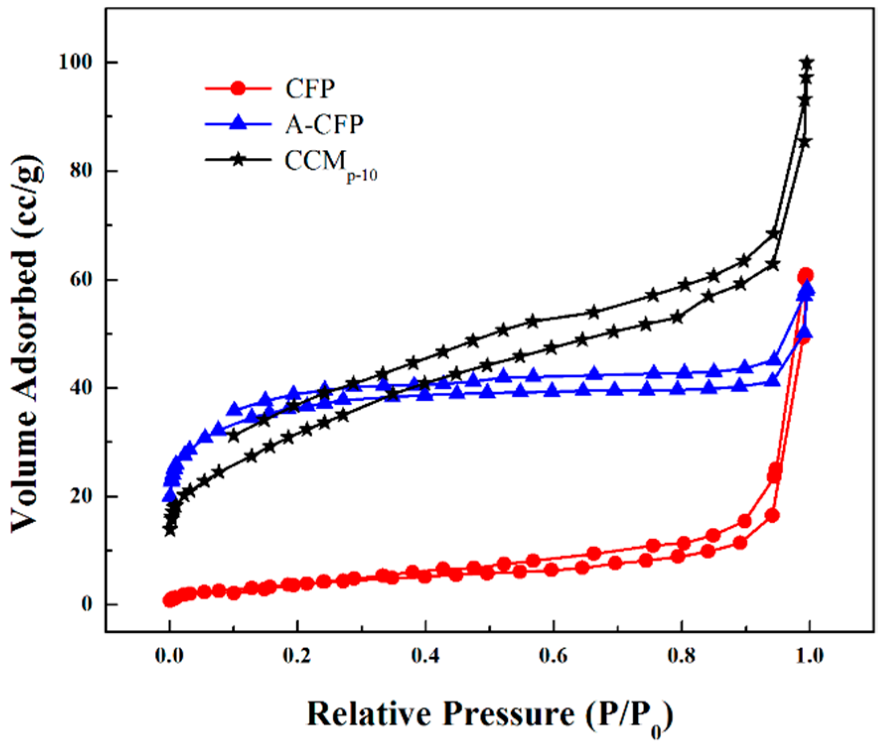
3.6. BET Analysis
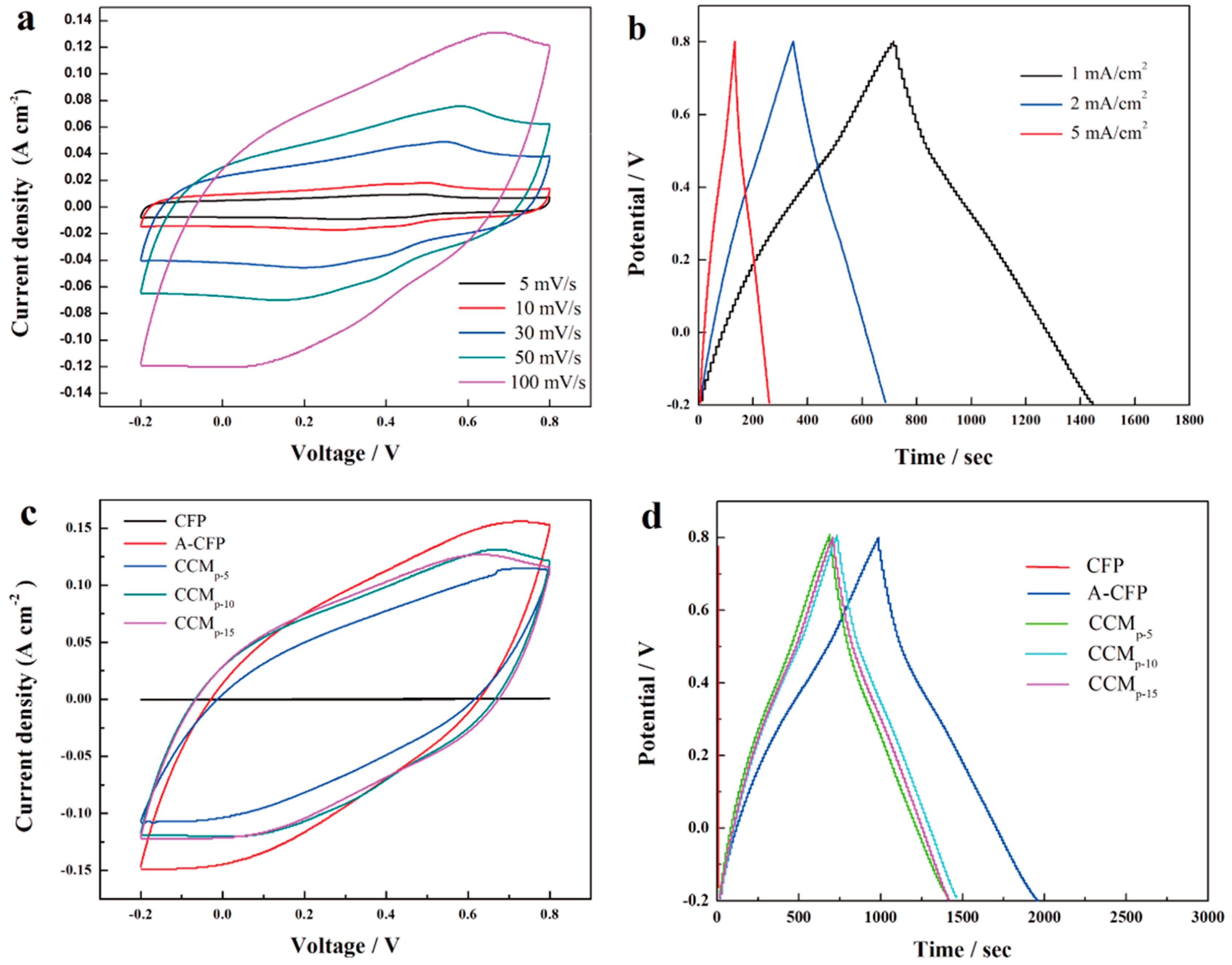
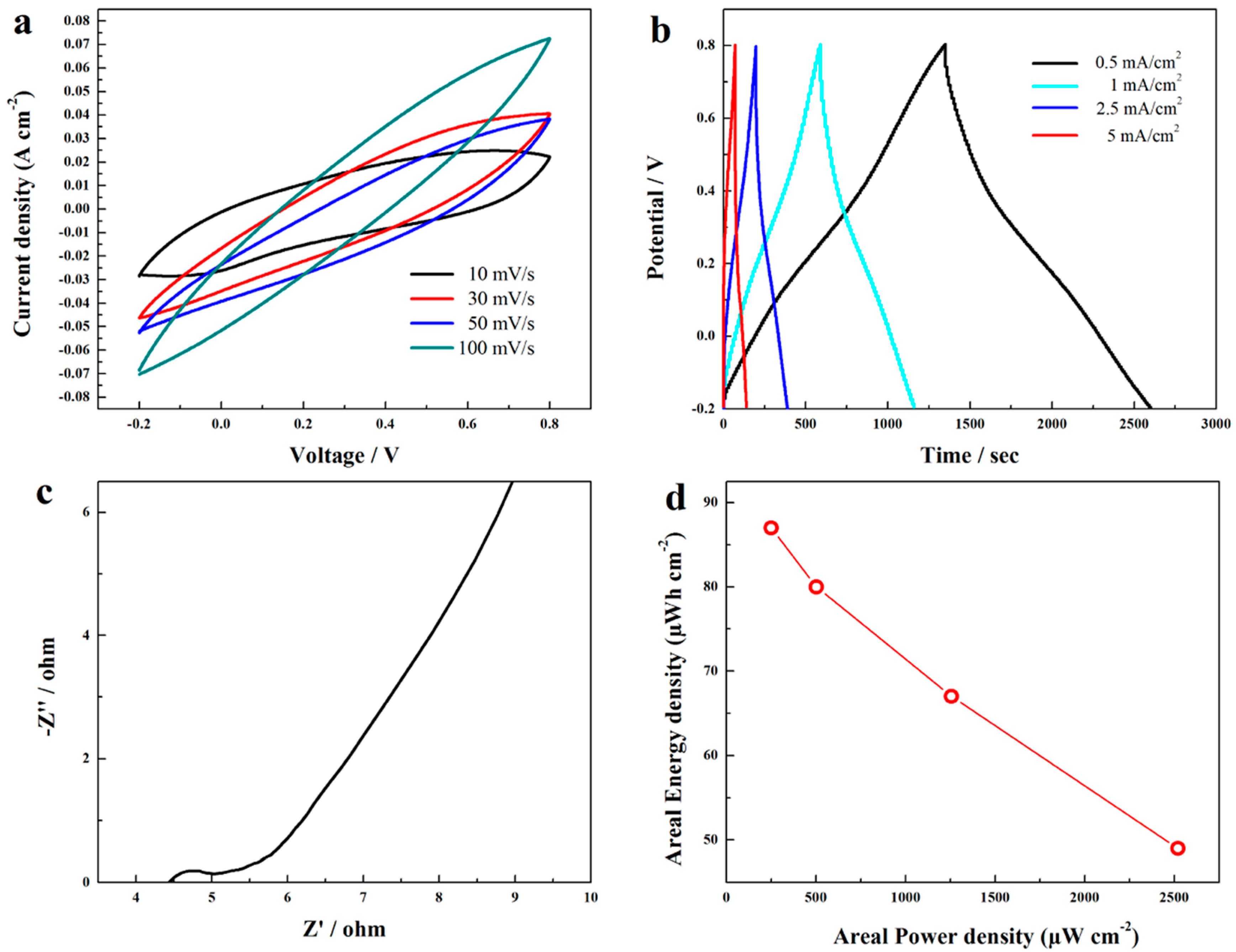
3.7. Electrochemical Characterization
4. Conclusions
Author Contributions
Funding
Acknowledgments
Conflicts of Interest
References
- Ma, C.; Li, Y.; Shi, J.; Song, Y.; Liu, L. High-performance supercapacitor electrodes based on porous flexible carbon nanofiber paper treated by surface chemical etching. Chem. Eng. J. 2014, 249, 216–225. [Google Scholar] [CrossRef]
- Srimuk, P.; Luanwuthi, S.; Krittayavathananon, A.; Sawangphruk, M. Solid-type supercapacitor of reduced graphene oxide-metal organic framework composite coated on carbon fiber paper. Electrochim. Acta 2015, 157, 69–77. [Google Scholar] [CrossRef]
- Xiao, J.; Wan, L.; Yang, S.; Xiao, F.; Wang, S. Design Hierarchical Electrodes with Highly Conductive NiCo2S4 Nanotube Arrays Grown on Carbon Fiber Paper for High-Performance Pseudocapacitors. Nano Lett. 2014, 14, 831–838. [Google Scholar] [CrossRef] [PubMed]
- Huang, L.; Chen, D.; Ding, Y.; Feng, S.; Wang, Z.L.; Liu, M. Nickel–Cobalt Hydroxide Nanosheets Coated on NiCo2O4 Nanowires Grown on Carbon Fiber Paper for High-Performance Pseudocapacitors. Nano Lett. 2013, 13, 3135–3139. [Google Scholar] [CrossRef] [PubMed]
- Rakhi, R.B.; Alshareef, H.N. Enhancement of the energy storage properties of supercapacitors using graphene nanosheets dispersed with metal oxide-loaded carbon nanotubes. J. Power Sources 2011, 196, 8858–8865. [Google Scholar] [CrossRef]
- Vangari, M.; Pryor, T.; Jiang, L. Supercapacitors: Review of Materials and Fabrication Methods. J. Energy Eng. 2013, 139, 72–79. [Google Scholar] [CrossRef]
- Muniraj, V.K.A.; Kamaja, C.K.; Shelke, M.V. RuO2·nH2O Nanoparticles Anchored on Carbon Nano-onions: An Efficient Electrode for Solid State Flexible Electrochemical Supercapacitor. ACS Sustain. Chem. Eng. 2016, 4, 2528–2534. [Google Scholar] [CrossRef]
- Sumboja, A.; Foo, C.Y.; Wang, X.; Lee, P.S. Large Areal Mass, Flexible and Free-Standing Reduced Graphene Oxide/Manganese Dioxide Paper for Asymmetric Supercapacitor Device. Adv. Mater. 2013, 25, 2809–2815. [Google Scholar] [CrossRef] [PubMed]
- Rakhi, R.B.; Chen, W.; Hedhili, M.N.; Cha, D.; Alshareef, H.N. Enhanced Rate Performance of Mesoporous Co3O4 Nanosheet Supercapacitor Electrodes by Hydrous RuO2 Nanoparticle Decoration. ACS Appl. Mater. Interfaces 2014, 6, 4196–4206. [Google Scholar] [CrossRef] [PubMed]
- Yu, G.; Hu, L.; Liu, N.; Wang, H.; Vosgueritchian, M.; Yang, Y.; Cui, Y.; Bao, Z. Enhancing the Supercapacitor Performance of Graphene/MnO2 Nanostructured Electrodes by Conductive Wrapping. Nano Lett. 2011, 11, 4438–4442. [Google Scholar] [CrossRef] [PubMed]
- Peng, H.; Ma, G.; Ying, W.; Wang, A.; Huang, H.; Lei, Z. In situ synthesis of polyaniline/sodium carboxymethyl cellulose nanorods for high-performance redox supercapacitors. J. Power Sources 2012, 211, 40–45. [Google Scholar] [CrossRef]
- Kim, J.-W.; Siochi, E.J.; Carpena-Núñez, J.; Wise, K.E.; Connell, J.W.; Lin, Y.; Wincheski, R.A. Polyaniline/Carbon Nanotube Sheet Nanocomposites: Fabrication and Characterization. ACS Appl. Mater. Interfaces 2013, 5, 8597–8606. [Google Scholar] [CrossRef] [PubMed]
- Wang, H.; Liu, J.; Chen, Z.; Chen, S.; Sum, T.C.; Lin, J.; Shen, Z.X. Synergistic capacitive behavior between polyaniline and carbon black. Electrochim. Acta 2017, 230, 236–244. [Google Scholar] [CrossRef]
- Niu, Z.; Luan, P.; Shao, Q.; Dong, H.; Li, J.; Chen, J.; Zhao, D.; Cai, L.; Zhou, W.; Chen, X.; et al. A “skeleton/skin” strategy for preparing ultrathin free-standing single-walled carbon nanotube/polyaniline films for high performance supercapacitor electrodes. Energy Environ. Sci. 2012, 5, 8726–8733. [Google Scholar] [CrossRef] [Green Version]
- Zhang, J.; Kong, L.-B.; Wang, B.; Luo, Y.-C.; Kang, L. In-situ electrochemical polymerization of multi-walled carbon nanotube/polyaniline composite films for electrochemical supercapacitors. Synth. Met. 2009, 159, 260–266. [Google Scholar] [CrossRef]
- Wang, K.; Meng, Q.; Zhang, Y.; Wei, Z.; Miao, M. High-Performance Two-Ply Yarn Supercapacitors Based on Carbon Nanotubes and Polyaniline Nanowire Arrays. Adv. Mater. 2013, 25, 1494–1498. [Google Scholar] [CrossRef] [PubMed]
- Zhu, W.; Zhang, Y.; Zhou, X.; Xu, J.; Liu, Z.; Yuan, N.; Ding, J. Miniaturized Stretchable and High-Rate Linear Supercapacitors. Nanoscale Res. Lett. 2017, 12. [Google Scholar] [CrossRef] [PubMed] [Green Version]
- Show, Y.; Imaizumi, K. Electric double layer capacitor with low series resistance fabricated by carbon nanotube addition. Diam. Relat. Mater. 2007, 16, 1154–1158. [Google Scholar] [CrossRef]
- Geng, Y.; Liu, M.Y.; Li, J.; Shi, X.M.; Kim, J.K. Effects of surfactant treatment on mechanical and electrical properties of CNT/epoxy nanocomposites. Compos. Part Appl. Sci. Manuf. 2008, 39, 1876–1883. [Google Scholar] [CrossRef]
- Shi, X.; Hu, Y.; Fu, F.; Zhou, J.; Wang, Y.; Chen, L.; Zhang, H.; Li, J.; Wang, X.; Zhang, L. Construction of PANI–cellulose composite fibers with good antistatic properties. J. Mater. Chem. A 2014, 2, 7669–7673. [Google Scholar] [CrossRef]
- Miao, C.; Hamad, W.Y. Cellulose reinforced polymer composites and nanocomposites: A critical review. Cellulose 2013, 20, 2221–2262. [Google Scholar] [CrossRef]
- Kim, Y.; McCoy, L.T.; Lee, E.; Lee, H.; Saremi, R.; Feit, C.; Hardin, I.R.; Sharma, S.; Mani, S.; Minko, S. Environmentally sound textile dyeing technology with nanofibrillated cellulose. Green Chem. 2017, 19, 4031–4035. [Google Scholar] [CrossRef]
- Czaja, W.K.; Young, D.J.; Kawecki, M.; Brown, R.M. The Future Prospects of Microbial Cellulose in Biomedical Applications. Biomacromolecules 2007, 8, 1–12. [Google Scholar] [CrossRef] [PubMed] [Green Version]
- Gui, Z.; Zhu, H.; Gillette, E.; Han, X.; Rubloff, G.W.; Hu, L.; Lee, S.B. Natural Cellulose Fiber as Substrate for Supercapacitor. ACS Nano 2013, 7, 6037–6046. [Google Scholar] [CrossRef] [PubMed]
- Siró, I.; Plackett, D. Microfibrillated cellulose and new nanocomposite materials: A review. Cellulose 2010, 17, 459–494. [Google Scholar] [CrossRef]
- Suktha, P.; Chiochan, P.; Iamprasertkun, P.; Wutthiprom, J.; Phattharasupakun, N.; Suksomboon, M.; Kaewsongpol, T.; Sirisinudomkit, P.; Pettong, T.; Sawangphruk, M. High-Performance Supercapacitor of Functionalized Carbon Fiber Paper with High Surface Ionic and Bulk Electronic Conductivity: Effect of Organic Functional Groups. Electrochim. Acta 2015, 176, 504–513. [Google Scholar] [CrossRef]
- Chen, W.; Yu, H.; Liu, Y. Preparation of millimeter-long cellulose I nanofibers with diameters of 30–80 nm from bamboo fibers. Carbohydr. Polym. 2011, 86, 453–461. [Google Scholar] [CrossRef]
- Yan, X.; Tai, Z.; Chen, J.; Xue, Q. Fabrication of carbon nanofiber–polyaniline composite flexible paper for supercapacitor. Nanoscale 2011, 3, 212–216. [Google Scholar] [CrossRef] [PubMed]
- Liu, S.; Li, D. Synthesis of chitin nanofibers, MWCNTs and MnO2 nanoflakes 3D porous network flexible gel-film for high supercapacitive performance electrodes. Appl. Surf. Sci. 2017, 398, 33–42. [Google Scholar] [CrossRef]
- Yang, C.; Chen, C.; Pan, Y.; Li, S.; Wang, F.; Li, J.; Li, N.; Li, X.; Zhang, Y.; Li, D. Flexible highly specific capacitance aerogel electrodes based on cellulose nanofibers, carbon nanotubes and polyaniline. Electrochim. Acta 2015, 182, 264–271. [Google Scholar] [CrossRef]
- Wang, Z.; Han, Y.; Zeng, Y.; Qie, Y.; Wang, Y.; Zheng, D.; Lu, X.; Tong, Y. Activated carbon fiber paper with exceptional capacitive performance as a robust electrode for supercapacitors. J. Mater. Chem. A 2016, 4, 5828–5833. [Google Scholar] [CrossRef]
- Zhang, F.; Pang, Z.; Dong, C.; Liu, Z. Preparing cationic cotton linter cellulose with high substitution degree by ultrasonic treatment. Carbohydr. Polym. 2015, 132, 214–220. [Google Scholar] [CrossRef] [PubMed]
- Zhu, Y.; Cheng, S.; Zhou, W.; Jia, J.; Yang, L.; Yao, M.; Wang, M.; Wu, P.; Luo, H.; Liu, M. Porous Functionalized Self-Standing Carbon Fiber Paper Electrodes for High-Performance Capacitive Energy Storage. ACS Appl. Mater. Interfaces 2017, 9, 13173–13180. [Google Scholar] [CrossRef] [PubMed]
- Gardner, S.D.; Singamsetty, C.S.K.; Booth, G.L.; He, G.-R.; Pittman, C.U., Jr. Surface characterization of carbon fibers using angle-resolved XPS and ISS. Carbon 1995, 33, 587–595. [Google Scholar] [CrossRef]
- Golczak, S.; Kanciurzewska, A.; Fahlman, M.; Langer, K.; Langer, J. Comparative XPS surface study of polyaniline thin films. Solid State Ion. 2008, 179, 2234–2239. [Google Scholar] [CrossRef]
- Kaewsongpol, T.; Sawangphruk, M.; Chiochan, P.; Suksomboon, M.; Suktha, P.; Srimuk, P.; Krittayavathananon, A.; Luanwuthi, S.; Iamprasertkun, P.; Wutthiprom, J.; et al. High-performance supercapacitor of electrodeposited porous 3D polyaniline nanorods on functionalized carbon fiber paper: Effects of hydrophobic and hydrophilic surfaces of conductive carbon paper substrates. Mater. Today Commun. 2015, 4, 176–185. [Google Scholar] [CrossRef]
- Zheng, Q.; Cai, Z.; Ma, Z.; Gong, S. Cellulose Nanofibril/Reduced Graphene Oxide/Carbon Nanotube Hybrid Aerogels for Highly Flexible and All-Solid-State Supercapacitors. ACS Appl. Mater. Interfaces 2015, 7, 3263–3271. [Google Scholar] [CrossRef] [PubMed]
- Lu, X.; Zeng, Y.; Yu, M.; Zhai, T.; Liang, C.; Xie, S.; Balogun, M.-S.; Tong, Y. Oxygen-Deficient Hematite Nanorods as High-Performance and Novel Negative Electrodes for Flexible Asymmetric Supercapacitors. Adv. Mater. 2014, 26, 3148–3155. [Google Scholar] [CrossRef] [PubMed]
- Gospodinova, N.; Mokreva, P.; Terlemezyan, L. Influence of hydrolysis on the chemical polymerization of aniline. Polymer 1994, 35, 3102–3106. [Google Scholar] [CrossRef]
- Zeng, S.; Chen, H.; Cai, F.; Kang, Y.; Chen, M.; Li, Q. Electrochemical fabrication of carbon nanotube/polyaniline hydrogel film for all-solid-state flexible supercapacitor with high areal capacitance. J. Mater. Chem. A 2015, 3, 23864–23870. [Google Scholar] [CrossRef]
- Qu, Y.; Lu, C.; Su, Y.; Cui, D.; He, Y.; Zhang, C.; Cai, M.; Zhang, F.; Feng, X.; Zhuang, X. Hierarchical-graphene-coupled polyaniline aerogels for electrochemical energy storage. Carbon 2018, 127, 77–84. [Google Scholar] [CrossRef]
- Zhang, H.; Qiu, W.; Zhang, Y.; Han, Y.; Yu, M.; Wang, Z.; Lu, X.; Tong, Y. Surface engineering of carbon fiber paper for efficient capacitive energy storage. J. Mater. Chem. A 2016, 4, 18639–18645. [Google Scholar] [CrossRef]
- Yang, C.; Zhang, L.; Hu, N.; Yang, Z.; Wei, H.; Wang, Y.; Zhang, Y. High-performance flexible all-solid-state supercapacitors based on densely-packed graphene/polypyrrole nanoparticle papers. Appl. Surf. Sci. 2016, 387, 666–673. [Google Scholar] [CrossRef]
- Zhou, Y.; Hu, X.; Shang, Y.; Hua, C.; Song, P.; Li, X.; Zhang, Y.; Cao, A. Highly flexible all-solid-state supercapacitors based on carbon nanotube/polypyrrole composite films and fibers. RSC Adv. 2016, 6, 62062–62070. [Google Scholar] [CrossRef]
- Liu, R.; Liu, C.; Fan, S. A photocapacitor based on organometal halide perovskite and PANI/CNT composites integrated using a CNT bridge. J. Mater. Chem. A 2017, 5, 23078–23084. [Google Scholar] [CrossRef]


| Electrode Materials | Electrolyte | Capacitance (mF·cm−2) | Ref. |
|---|---|---|---|
| CNT/PANI hydrogel film | 1 M H2SO4 | 680 | [40] |
| Graphene/PANI aerogels | H2SO4/PVA | 679 | [41] |
| Carbon fiber paper | 6 M KOH | 750 | [42] |
| Graphene/polypyrrole | H2SO4/PVA | 477 | [43] |
| CNT/polypyrrole | H3PO4/PVA | 27.8 | [44] |
| Organometal halide perovskite solar cells/CNT/PANI | PVA | 422 | [45] |
© 2018 by the authors. Licensee MDPI, Basel, Switzerland. This article is an open access article distributed under the terms and conditions of the Creative Commons Attribution (CC BY) license (http://creativecommons.org/licenses/by/4.0/).
Share and Cite
Tan, S.; Li, J.; Zhou, L.; Chen, P.; Shi, J.; Xu, Z. Modified Carbon Fiber Paper-Based Electrodes Wrapped by Conducting Polymers with Enhanced Electrochemical Performance for Supercapacitors. Polymers 2018, 10, 1072. https://doi.org/10.3390/polym10101072
Tan S, Li J, Zhou L, Chen P, Shi J, Xu Z. Modified Carbon Fiber Paper-Based Electrodes Wrapped by Conducting Polymers with Enhanced Electrochemical Performance for Supercapacitors. Polymers. 2018; 10(10):1072. https://doi.org/10.3390/polym10101072
Chicago/Turabian StyleTan, Sicong, Jiajia Li, Lijie Zhou, Peng Chen, Jiangtao Shi, and Zhaoyang Xu. 2018. "Modified Carbon Fiber Paper-Based Electrodes Wrapped by Conducting Polymers with Enhanced Electrochemical Performance for Supercapacitors" Polymers 10, no. 10: 1072. https://doi.org/10.3390/polym10101072