TiO2 Coated ZnO Nanorods by Mist Chemical Vapor Deposition for Application as Photoanodes for Dye-Sensitized Solar Cells


1
School of Systems Engineering, Kochi University of Technology, Kami, Kochi 782-8502, Japan
2
Center for Nanotechnology, Kochi University of Technology, Kami, Kochi 782-8502, Japan
*
Author to whom correspondence should be addressed.
Nanomaterials 2019, 9(9), 1339; https://doi.org/10.3390/nano9091339
Submission received: 13 August 2019
/
Revised: 12 September 2019
/
Accepted: 15 September 2019
/
Published: 19 September 2019
(This article belongs to the Special Issue Nanoparticles for Photovoltaics)
Abstract
:In this study, a mist chemical vapor deposition method was applied to create a coating of titanium dioxide particles in order to fabricate ZnO/TiO2 core–shell nanostructures. The thin layers of titanium dioxide on the zinc oxide nanorods were uniform and confirmed as pure anatase phase. The morphological, structural, optical and photoluminescence properties of the ZnO/TiO2 core–shell structures were influenced by coating time. For instance, the crystallinity of the titanium dioxide increased in accordance with an increase in the duration of the coating time. Additionally, the thickness of the titanium dioxide layer gradually increased with the coating time, resulting in an increased surface area. The transmittance of the arrayed ZnO/TiO2 core–shell structures was 65% after 15 min of coating. The obtained ZnO/TiO2 core–shell nanostructures demonstrated high potentiality to serve as photoanodes for application in dye-sensitized solar cells.
1. Introduction
Since Brian O’Regan and Michael Grätzel developed dye-sensitized solar cells (DSSCs) in 1991 [1], DSSCs have been widely investigated as a promising alternative to conventional photovoltaic devices due to their low fabrication cost, nontoxicity and promising conversion efficiency [2,3]. Hitherto, titanium dioxide (TiO2)-based DSSCs have been reported to achieve a notable power conversion efficiency (PCE) of more than 14% [4]. In order to improve the PCE, four dominant functions—specifically the photoanodes, dye, electrolyte and counter electrodes—need to be optimized. Photoanodes in particular have a strong influence on the PCE of DSSCs due to their electron injection and transportation processes. Further improvement in the PCE of TiO2-based DSSCs is difficult due to the intrinsic properties of TiO2, such as the difficulty of constructing TiO2 nanostructures, which limits the surface area of TiO2 photoanodes in a DSSC. The low carrier transportation rate of TiO2 also leads to low electron mobility in photoanodes [5,6]. Recently, zinc oxide (ZnO) has attracted much attention as an alternative photoanode material because it exhibits a similar bandgap (3.37 eV at room temperature) and electron injection process from excited dyes as TiO2 [7]. Additionally, ZnO achieves a much higher electron mobility (200~1000 cm2/(V∙s)) than TiO2 (0.1~4 cm2/(V∙s)) [8], which may enhance its electron transportation. Moreover, ZnO is much easier to fabricate into various nanostructures with good alignment, which increases its light absorption [9]. Therefore, ZnO is expected to be a promising photoanode material to improve the conversion efficiency of DSSCs. Compared with random ZnO particles, one-dimensional ZnO nanostructures, including nanotubes, nanorods and nanowires, are intended to facilitate fast electron transfer and thereby reduce electron recombination in DSSCs [10].
It has been reported that the highest power conversion efficiency of a pure ZnO-based DSSC is 7.5% [10,11], which is much lower than that of a TiO2-based DSSC [4]. First, due to its poor chemical stability, ZnO can be easily dissolved in both acidic and strong alkaline solutions at room temperature. Therefore, pure ZnO photoanodes are easy to dissolve in acidic dye and electrolyte solutions. Moreover, some defects of ZnO increase electron–hole recombination and Zn2+/dye complex formation at the interface [12,13,14,15]. One solution to overcome such disadvantages is to fabricate a core–shell structure by coating a chemically stable shell onto ZnO. This core–shell structure forms an energy barrier that can reduce electron—hole recombination and passivate the ZnO surface, thereby reducing the formation of the Zn2+/dye complex [16]. Compared with ZnO, TiO2 shows excellent chemical stability; it is stable in all alkaline solutions and most acidic solutions (except hydrofluoric acid) at room temperature. By coating a TiO2 shell onto the whole surface of a ZnO photoanode, the chemical stability of the photoanode should be significantly improved (equal to the chemical stability of TiO2), while the electron–hole recombination on the surface of the ZnO photoanode should also be reduced. Therefore, ZnO/TiO2 core–shell nanorods are one of the most promising nanocomposites. It has been reported that the PCE of DSSCs with pure ZnO photoanodes can be improved by about 1 to 5 times by coating a TiO2 shell onto the ZnO photoanodes [17,18,19,20]. Among the three phases of TiO2, brookite phase TiO2 is the most difficult to fabricate into a thin film [21,22], while anatase phase TiO2 has a band gap (~3.2 eV) more similar to ZnO (~3.37 eV) than rutile phase TiO2 (~3.0 eV) [23,24]. Previous studies have reported that ZnO nanorods can be coated with a TiO2 layer by the solution method, the sol-gel method or atomic layer deposition [25,26,27]. However, control of the phase, thickness and uniformity of the TiO2 layer remain unsolved issues. According to our previous research [28,29], mist chemical vapor deposition (mist CVD) [30] is an effective method of synthesizing pure anatase phase TiO2 thin films.
In this study, the mist CVD system consisted of two stages: A stage involving the creation of mist droplets and a deposition stage (in a reaction chamber). In the first stage, mist droplets were transformed from a solution of precursors by three ultrasonic transducers (2.4 MHz). Then, the mist droplets were transported into a reaction chamber by carrier and dilution gases. During transportation in the specially-designed reaction chamber, the size of the mist droplets was decreased from the microscale to the nanoscale. The nanoscale was maintained until deposition. Due to gravity and adsorption, the mist droplets moved effectively onto the substrate, which was set in the reaction chamber with the appropriate heating [28,30].
In our previous research, well-arrayed ZnO nanorods with high transmittance (over 70% in the visible region) were fabricated using a chemical bath deposition (CBD) method [31,32,33]. Here, in order to obtain photoanodes with excellent chemical stability, high transmittance, and high electron mobility, we employed both the mist CVD and CBD methods to fabricate ZnO/TiO2 core–shell nanorods by coating ZnO nanorods with TiO2 particles.
2. Materials and Methods
2.1. Fabrication of ZnO/TiO2 Core–Shell Nanorods
Aluminum oxide (2 wt.%)-doped ZnO (AZO) thin films with 300 nm thickness were deposited on alkali-free glass sheets (Eagle XG, Corning Inc., Corning, NY, USA) by a conventional 13.56 MHz radio frequency (RF) magnetron sputtering system. Following the deposition of the AZO films, ZnO nanorods were fabricated on the AZO substrates by CBD. During the CBD process, the substrates were immersed in a solution containing Zn(NO3)2 and hexamethylenetetramine (C6H12N4, HMTA) for 5 h at 95 °C. The deposition conditions for the AZO film and ZnO nanorods are shown in Table 1 and Table 2, respectively. After deposition, the obtained ZnO nanorods were coated with TiO2 by the mist CVD method. The deposition conditions for coating are shown in Table 3.
2.2. Characterization
The morphological properties of the ZnO nanorods were evaluated at 5 kV by a field emission scanning electron microscope (FESEM, SU-8020, Hitachi, Tokyo, Japan). Energy dispersive X-ray spectroscopy (EDS) analysis was performed at 15 kV using a silicon drift detector (SDD, X-Max, Horiba, Tokyo, Japan) fitted to the FESEM. The structural properties were investigated by grazing incidence X-ray diffraction (GIXRD, ATX-G, Rigaku, Tokyo, Japan) with an incidence angle of 0.35° and Raman spectroscopy (LabRAM HR-800, Horiba Jobin Yvon, Longjumeau, France) with a 532.8 nm excitation laser. Transmittance measurements were acquired using a spectrophotometer (U-4100, Hitachi, Tokyo, Japan). The photoluminescence (PL) spectra were acquired by a micro-PL/Raman spectroscope (iHR320, Horiba, Tokyo, Japan) with a 325 nm He-Cd laser as the excitation light source. All measurements were carried out at room temperature.
3. Results
The proposed mechanism of ZnO/TiO2 core–shell nanorod fabrication is shown in Figure 1. First, the ZnO nanorods were prepared on the AZO film, which acted as a seed layer, by the CBD method. After the CBD process, the obtained ZnO nanorods were placed in the reaction chamber for mist CVD. During the mist CVD process, the mist droplets—including both titanium tetraisopropoxide (TTIP) and ethanol—were transformed from the solution of precursors by ultrasonic transducers. Following this, the mist droplets were transported onto the surface of the ZnO nanorods by carrier and dilution gases. During transportation of the mist droplets in the reaction chamber, the size of the mist droplets decreased from a few micrometers to a few nanometers under the influence of heat, evapotranspiration and burst. Finally, anatase phase TiO2 particle shells were deposited on the surface of the ZnO nanorods due to the pyrolysis reaction of TTIP at 400 °C [28].
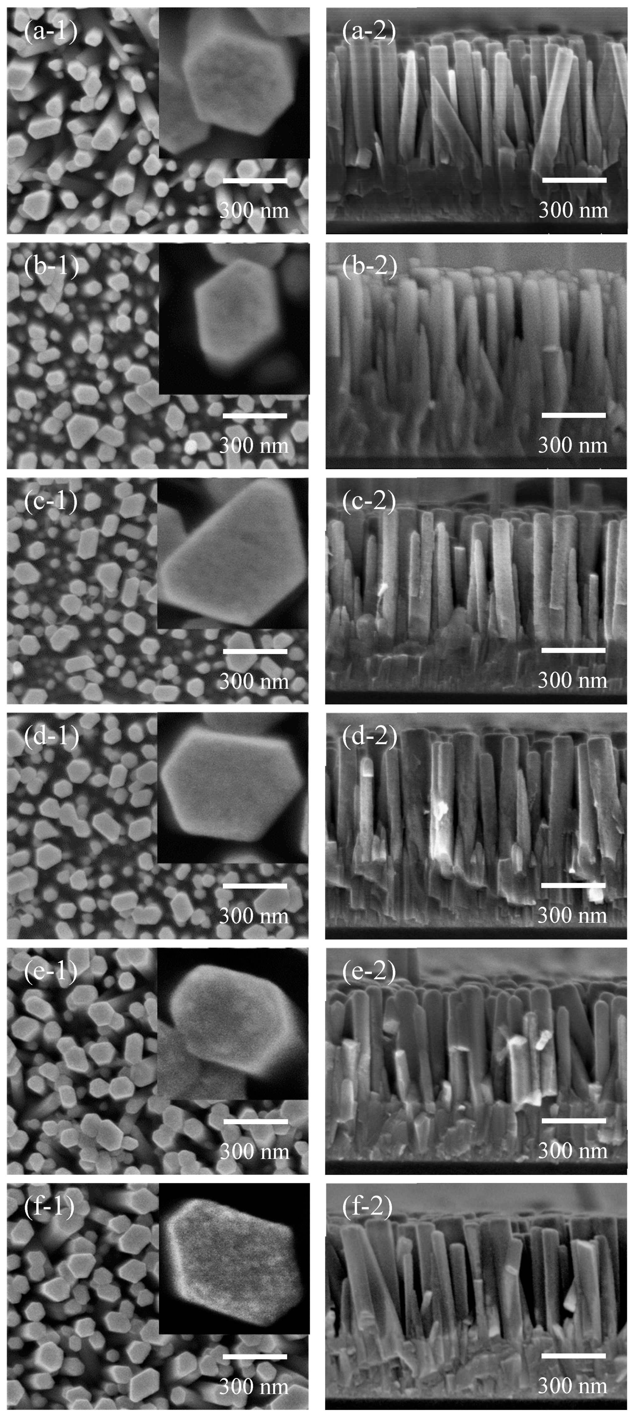
Figure 2 shows SEM images of the as-deposited ZnO nanorods and ZnO nanorods coated with TiO2 by mist CVD. From the top view images, uniform ZnO nanorods with hexagonal structure were obtained on the AZO substrate after the CBD process. The inset images in the top view images show the surface of a single ZnO nanorod. Compared with the as-deposited ZnO nanorods, no obvious changes were observed on the surface of the nanorods coated with TiO2 for 30 s, 2 min and 5 min. When the TiO2 coating time was increased to 10 min and 15 min, TiO2 particles were observed on the surface of the ZnO nanorods. Compared with the relatively smooth surface of the as-deposited ZnO nanorods, the ZnO nanorods coated with TiO2 for 15 min showed a rough surface with many TiO2 particles, indicating the surface area of the nanorods had increased. A larger surface area of photoanodes in a DSSC enhances its adsorption of dye, which may improve the PCE of the DSSC. Based on the cross section view images, it appeared the ZnO nanorods grew vertically on the AZO substrates, and the average length of the ZnO nanorods was around 600 nm. The SEM results revealed that the TiO2 particle layers on the ZnO nanorods were uniform.
EDS elemental mapping images of the ZnO nanorods coated with TiO2 for 10 min are shown in Figure 3. The elemental mappings of zinc, titanium and oxygen are shown in Figure 3b–d, respectively. As shown in Figure 3c, elemental titanium was confirmed from the bottom to the top of the ZnO nanorods, indicating that the whole surface of the nanorods was successfully coated with TiO2 particles. Considering electron mobility and chemical stability are essential attributes of materials, the TiO2 shell that covers the whole surface of a ZnO nanorod will significantly improve the chemical stability of ZnO photoanodes, and the ZnO nanorod inside the TiO2 shell will significantly improve the electron mobility of TiO2 photoanodes. This TiO2 shell is also capable of reducing electron–hole recombination on the surface of ZnO photoanodes. Therefore, the fabrication of ZnO/TiO2 core–shell nanorods solves the shortcomings of TiO2 photoanodes (low electron mobility) and ZnO photoanodes (poor chemical stability).
Figure 4 shows the GIXRD patterns of as-deposited ZnO nanorods and ZnO nanorods coated with TiO2 by mist CVD. The observed peaks corresponded with the diffractions from (100), (002), (101), (102), (110), (103), and (112) crystal planes of ZnO. It was clear that the (103) peaks were the dominant peaks, which was due to the low incidence angle (0.35°) employed in the GIXRD analysis. After coating TiO2 for 30 s and 2 min, the intensity of the ZnO peaks between 30° and 40° decreased, suggesting the growth of TiO2 on the surface of the ZnO nanorods. When the TiO2 coating time was increased from 2 min through each time interval to 15 min, an increasing trend in the intensity of the ZnO peaks was observed. This could be attributed to annealing effects during the mist CVD process, which was operated at 400 °C. The crystallinity of the ZnO nanorods was improved by the annealing effects. The inset image in Figure 4 shows the details of the GIXRD patterns from 20° to 30°. In this inset, no peak of TiO2 may be observed from the ZnO nanorods coated with TiO2 for 30 s, 2 min or 5 min, which may be due to insufficient thickness of the TiO2 layer. A (101) diffraction peak, which corresponds with anatase phase TiO2, was observed at 2 θ of 25.3° when the TiO2 coating time was increased to 10 min and 15 min. The intensity of the TiO2 (101) diffraction peak increased as the TiO2 coating time increased, indicating the thickness of the TiO2 layer increased.
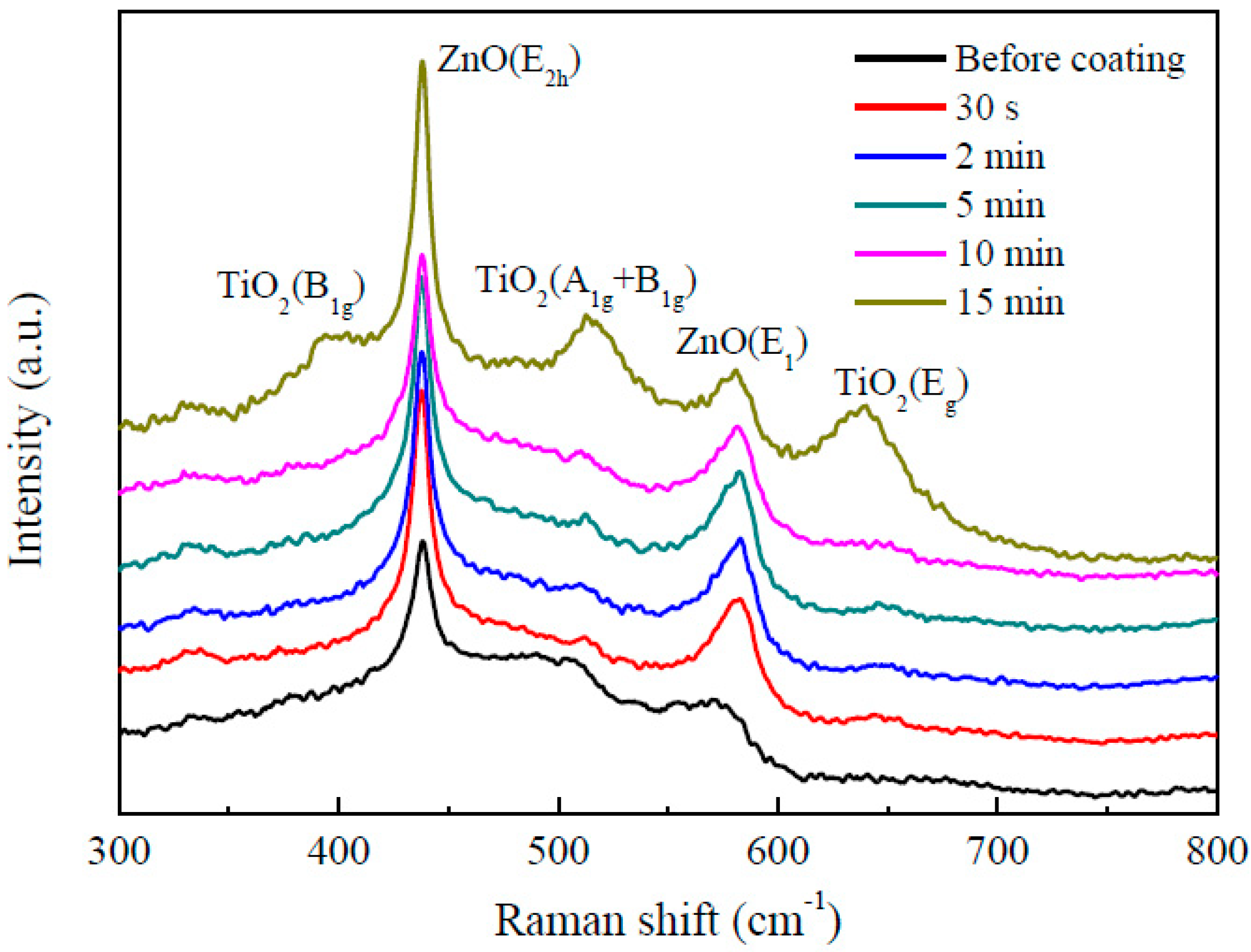
Figure 5 shows the Raman spectra of the as-deposited ZnO nanorods and ZnO nanorods coated with TiO2 by mist CVD. The peaks at 438 cm−1 and 582 cm−1 were assigned to the E2h mode and E1 (LO) mode of ZnO, respectively. Three more peaks were observed in the Raman spectrum for the ZnO nanorods coated with TiO2 for 15 min. The peaks at 398 cm−1, 639 cm−1 and 515 cm−1 corresponded respectively with the B1g mode, Eg mode and a doublet of the A1g and B1g modes of anatase phase TiO2, suggesting the ZnO nanorods were coated with TiO2 successfully. This result was in agreement with those from the EDS and GIXRD measurements.
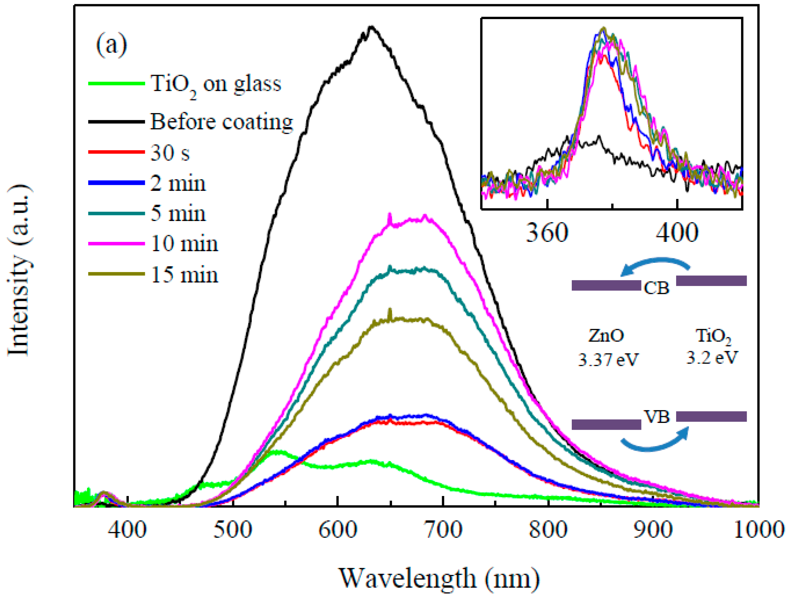
PL spectroscopy is a well-established tool for understanding the fate of photoinduced charge carriers and interfacial charge transfer [34,35,36,37]. The PL spectra of the TiO2 film on glass, as-deposited ZnO nanorods and ZnO nanorods coated with TiO2 by mist CVD are shown in Figure 6a. The inset image shows the details of the PL spectra from 340 nm to 420 nm. The as-deposited ZnO nanorods showed a weak ultraviolet (UV) emission centered at 370 nm and a strong visible emission centered at 632 nm. The UV emission of the as-deposited ZnO nanorods corresponded with the band gap of ZnO (around 3.37 eV). Compared with the as-deposited ZnO nanorods, the UV emission of the ZnO nanorods coated with TiO2 for 30 s and 2 min showed a slight red shift. As the TiO2 coating time increased from 2 min to 15 min, the UV emission red-shifted gradually to 382 nm, which corresponds with the band gap of anatase phase TiO2 (around 3.2 eV). A PL emission of TiO2 from 400 nm to 700 nm was not observed for the ZnO nanorods coated with TiO2. This PL quenching of TiO2 suggests a charge transfer from TiO2 to ZnO.
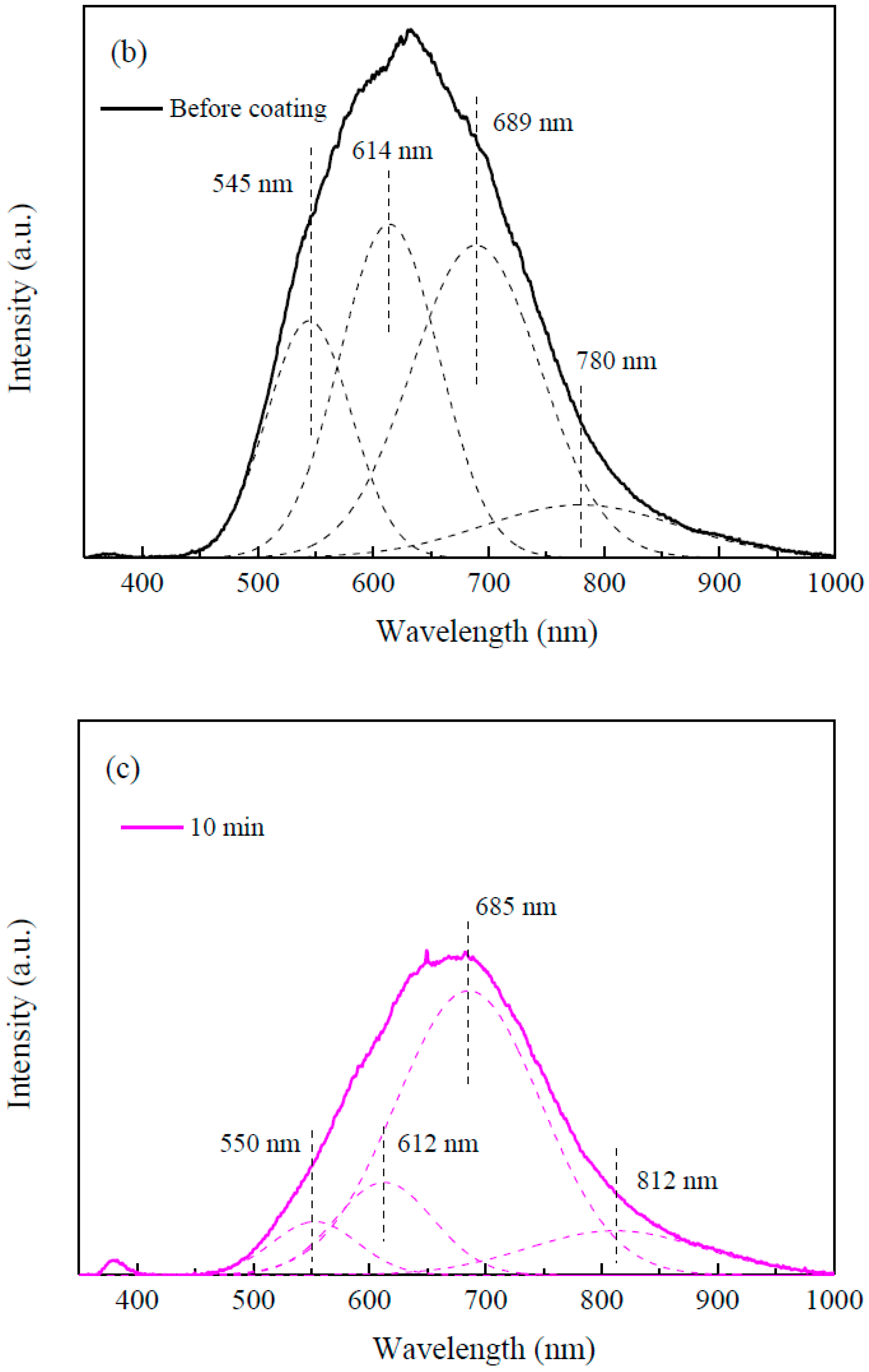
According to the curve fitting for the as-deposited ZnO nanorods visible emission, shown in Figure 6b, the visible emission peak of the as-deposited ZnO nanorods was divided into four emission peaks (dashed line). The emission peaks of the as-deposited ZnO nanorods located at 545 nm (~2.27 eV) and 614 nm (~2.02 eV) may be attributed to oxygen vacancies [38,39,40,41], while the emission peaks located at 689 nm (~1.80 eV) and 780 nm (~1.59 eV) may be attributed to oxygen interstitials [38]. It was observed that the visible emission of the ZnO nanorods showed a red shift after coating with TiO2. After the ZnO nanorods were coated with TiO2 for 30 s, the peak intensity of the visible emission decreased steeply. As the TiO2 coating time increased from 30 s to 15 min, the peak intensity of the visible emission first increased and then decreased. The highest visible emission peak intensity of the ZnO/TiO2 core–shell nanorods was obtained with a TiO2 coating time of 10 min. The curve fitting of visible emission of the ZnO nanorods coated with TiO2 for 10 min is shown in Figure 6c. After curve fitting, the visible emission peak was divided into four emission peaks (dashed line). Similar to the discussion of the as-deposited ZnO nanorods above, the emission peaks located at 550 nm and 612 nm may be attributed to oxygen vacancies in the ZnO nanorods, and the emission peak located at 685 nm may be attributed to oxygen interstitials. The broad emission peak centered at 812 nm (~1.53 eV) may be attributed to oxygen interstitials in the ZnO nanorods and titanium interstitials in the TiO2 coating [42,43]. Based on the curve fitting results, the red shift of the ZnO nanorods’ visible emission was attributed to the intensity decrease of the emissions located at around 550 nm and 612 nm, which was due to the annealing effects during the mist CVD process.
The PL results indicated that all of the defects in ZnO could be decreased by coating it with TiO2. The oxygen interstitials in ZnO were decreased slightly after coating with TiO2. The oxygen vacancies in ZnO were significantly decreased due to the annealing effects during the mist CVD process. Such a decrease in the defects of a photoanode can lead to a decrease in electron–hole recombination, which may, in turn, contribute to a higher PCE of DSSCs.
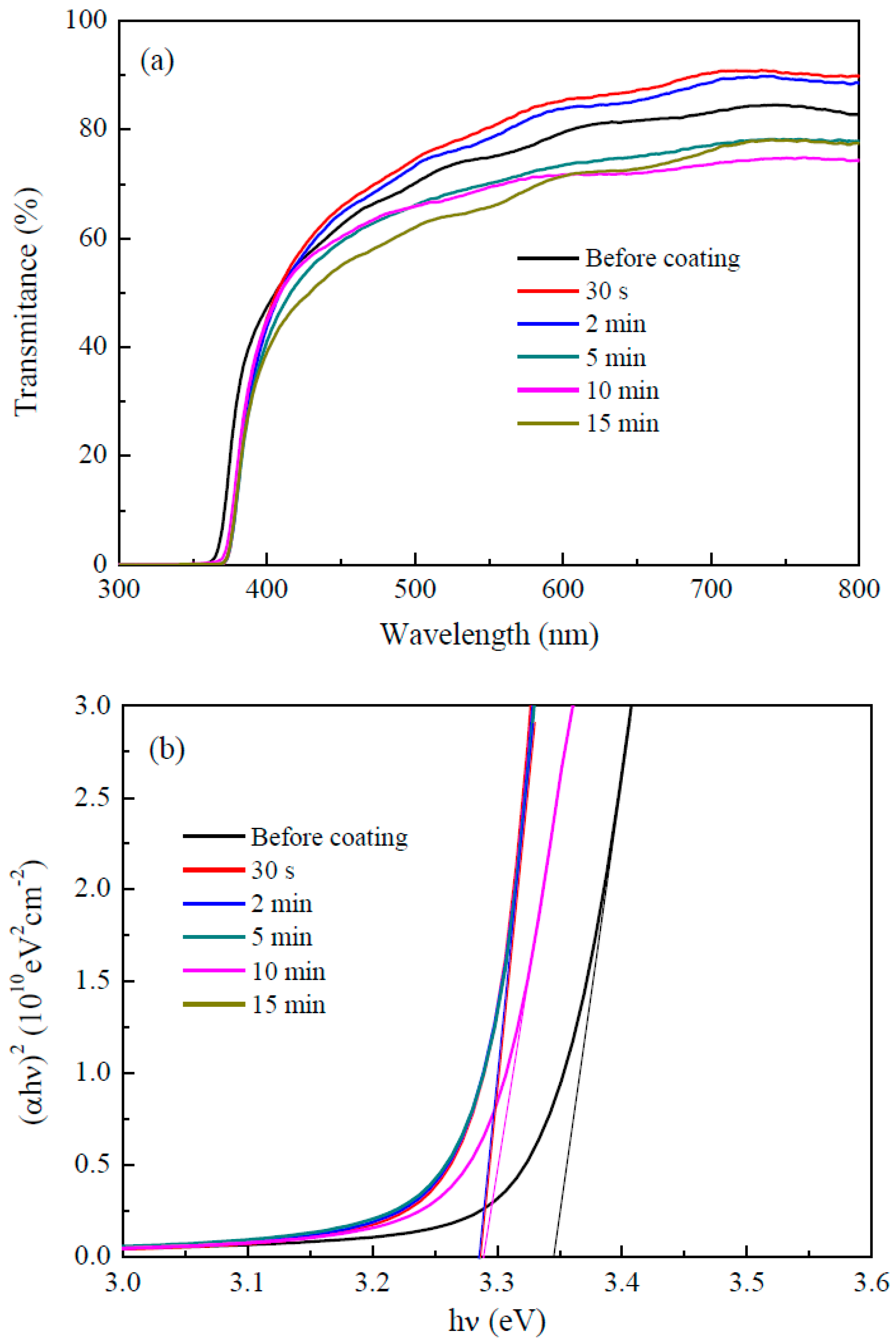
The transmission spectra of the as-deposited ZnO nanorods and ZnO nanorods coated with TiO2 by mist CVD are shown in Figure 7a. The transmittance of the as-deposited ZnO nanorods was around 75% in the visible region. The transmittance gradually decreased to around 65% as the TiO2 coating time was increased from 30 s to 15 min.
The bandgap (Eg) of the as-deposited ZnO nanorods and ZnO nanorods coated with TiO2 could be obtained from the transmittance and absorbance of the ZnO nanorods using the following equations [44]:
where α is the absorption coefficient, hν the incidence photon energy, A a constant, d the film thickness, and T the transmittance. As shown in Figure 7b, a plot of (αhν)2 as a function of hν was made to determine Eg by linear fitting. After fitting, the Eg of the as-deposited ZnO nanorods was around 3.34 eV, which corresponds with the band gap of bulk ZnO (3.37 eV). The Eg of ZnO/TiO2 core–shell nanorods was around 3.28 eV, which corresponds with the band gap of anatase phase TiO2 (3.2 eV).
4. Conclusions
Well-arrayed ZnO/TiO2 core–shell nanorods were successfully fabricated on an AZO substrate. We found that mist CVD was a successful method for coating thin layers of TiO2 onto ZnO nanorods. The TiO2 shells on the ZnO nanorods were confirmed as pure anatase phase, which contributes toward high chemical stability as photoanodes. The surface area of the ZnO nanorods was significantly increased with an increase in the TiO2 coating time. The transmittance of the ZnO nanorods decreased from 75% to 65% after 15 min of coating with TiO2. The well-arrayed ZnO/TiO2 core–shell nanorods contribute to a high transmittance (around 70%), greater electron transfer, greater chemical stability, and a relatively large surface area for dye absorption. As such, these nanorods are expected to be applied as photoanodes to improve the PCE for DSSCs.
Author Contributions
Conceptualization, Q.Z.; methodology, Q.Z.; investigation, Q.Z.; data curation, Q.Z.; writing—original draft preparation, Q.Z.; writing—review & editing, C.L.; visualization, C.L.; supervision, C.L.; project administration, C.L.; funding acquisition, C.L.
Funding
This research was funded by [the Ministry of Education, Culture, Sports, Science, and Technology (MEXT) in Japan, grant number [17K06394].
Acknowledgments
The authors gratefully acknowledge the financial support by Grant-in-Aid for Scientific Research from the Ministry of Education, Culture, Sports, Science, and Technology (MEXT), Japan.
Conflicts of Interest
The authors declare no conflict of interest.
References
- Regan, B.O.; Gratzel, M. A low-cost, high-efficiency solar cell based on dye-sensitized. Nature 1991, 353, 737–740. [Google Scholar] [CrossRef]
- Yang, L.; Leung, W.W.F. Application of a bilayer TiO2 nanofiber photoanode for optimization of dye-sensitized solar cells. Adv. Mater. 2011, 23, 4559–4562. [Google Scholar] [CrossRef] [PubMed]
- Graetzel, M.; Janssen, R.A.J.; Mitzi, D.B.; Sargent, E.H. Materials interface engineering for solution-processed photovoltaics. Nature 2012, 488, 304–312. [Google Scholar] [CrossRef] [PubMed]
- Kakiage, K.; Aoyama, Y.; Yano, T.; Oya, K.; Fujisawa, J.I.; Hanaya, M. Highly-efficient dye-sensitized solar cells with collaborative sensitization by silyl-anchor and carboxy-anchor dyes. Chem. Commun. 2015, 51, 15894–15897. [Google Scholar] [CrossRef] [PubMed]
- Law, M.; Greene, L.E.; Johnson, J.C.; Saykally, R.; Yang, P. Nanowire dye-sensitized solar cells. Nat. Mater. 2005, 4, 455–459. [Google Scholar] [CrossRef] [PubMed]
- Zhang, Q.; Dandeneau, C.S.; Zhou, X.; Cao, G. ZnO nanostructures for dye-sensitized solar cells. Adv. Mater. 2009, 21, 4087–4108. [Google Scholar] [CrossRef]
- Kolodziejczak-Radzimska, A.; Jesionowski, T. Zinc oxide-from synthesis to application: A review. Materials 2014, 7, 2833–2881. [Google Scholar] [CrossRef]
- Tiwana, P.; Docampo, P.; Johnston, M.B.; Snaith, H.J.; Herz, L.M. Electron mobility and injection dynamics in mesoporous ZnO, SnO2, and TiO2 films used in dye-sensitized solar cells. ACS Nano 2011, 5, 5158–5166. [Google Scholar] [CrossRef]
- Gonzalez-Valls, I.; Lira-Cantu, M. Vertically-aligned nanostructures of ZnO for excitonic solar cells: A review. Energy Environ. Sci. 2009, 2, 19–34. [Google Scholar] [CrossRef]
- Vittal, R.; Ho, K.C. Zinc oxide based dye-sensitized solar cells: A review. Renew. Sustain. Energy Rev. 2017, 70, 920–935. [Google Scholar] [CrossRef]
- Memarian, N.; Concina, I.; Braga, A.; Rozati, S.M.; Vomiero, A.; Sberveglieri, G. Hierarchically assembled ZnO nanocrystallites for high-efficiency dye-sensitized solar cells. Angew. Chem. Int. Ed. 2011, 50, 12321–12325. [Google Scholar] [CrossRef] [PubMed]
- Lu, L.; Li, R.; Fan, K.; Peng, T. Effects of annealing conditions on the photoelectrochemical properties of dye-sensitized solar cells made with ZnO nanoparticles. Sol. Energy 2010, 84, 844–853. [Google Scholar] [CrossRef]
- Ambade, S.B.; Mane, R.S.; Ghule, A.V.; Takwale, M.G.; Abhyankar, A.; Cho, B.W.; Han, S.H. Contact angle measurement: A preliminary diagnostic method for evaluating the performance of ZnO platelet-based dye-sensitized solar cells. Scr. Mater. 2009, 61, 12–15. [Google Scholar] [CrossRef]
- Yan, F.; Huang, L.; Zheng, J.; Huang, J.; Lin, Z.; Huang, F.; Wei, M. Effect of surface etching on the efficiency of ZnO-based dye-sensitized solar cells. Langmuir 2010, 26, 7153–7156. [Google Scholar] [CrossRef] [PubMed]
- Horiuchi, H.; Katoh, R.; Hara, K.; Yanagida, M.; Murata, S.; Arakawa, H.; Tachiya, M. Electron injection efficiency from excited N3 into nanocrystalline ZnO films: Effect of (N3-Zn2+) aggregate formation. J. Phys. Chem. B 2003, 107, 2570–2574. [Google Scholar] [CrossRef]
- Law, M.; Greene, L.E.; Radenovic, A.; Kuykendall, T.; Liphardt, J.; Yang, P. ZnO-Al2O3 and ZnO-TiO2 core-shell nanowire dye-sensitized solar cells. J. Phys. Chem. B 2006, 110, 22652–22663. [Google Scholar] [CrossRef] [PubMed]
- Chandiran, A.K.; Abdi-Jalebi, M.; Nazeeruddin, M.K.; Grätzel, M. Analysis of electron transfer properties of ZnO and TiO2 photoanodes for dye-sensitized solar cells. ACS Nano 2014, 8, 2261–2268. [Google Scholar] [CrossRef] [PubMed]
- Atienzar, P.; Ishwara, T.; Illy, B.N.; Ryan, M.P.; O’Regan, B.C.; Durrant, J.R.; Nelson, J. Control of photocurrent generation in polymer/ZnO nanorod solar cells by using a solution-processed TiO2 overlayer. J. Phys. Chem. Lett. 2010, 1, 708–713. [Google Scholar] [CrossRef]
- Feng, Y.; Ji, X.; Duan, J.; Zhu, J.; Jiang, J.; Ding, H.; Meng, G.; Ding, R.; Liu, J.; Hu, A.; et al. Synthesis of ZnO@TiO2 core-shell long nanowire arrays and their application on dye-sensitized solar cells. J. Solid State Chem. 2012, 190, 303–308. [Google Scholar] [CrossRef]
- Prabakar, K.; Son, M.; Kim, W.Y.; Kim, H. TiO2 thin film encapsulated ZnO nanorod and nanoflower dye sensitized solar cells. Mater. Chem. Phys. 2011, 125, 12–14. [Google Scholar] [CrossRef]
- Paola, A.D.; Bellardita, M.; Palmisano, L. Brookite, the Least Known TiO2 Photocatalyst. Catalysts 2013, 3, 36–73. [Google Scholar] [CrossRef]
- Moret, M.P.; Zallen, R.; Vijay, D.P.; Desu, S.B. Broo Kite-Rich Titania Films Made by Pulsed Laser Deposition. Thin Solid Films 2000, 366, 8–10. [Google Scholar] [CrossRef]
- Sennik, E.; Kilinc, N.; Ozturk, Z.Z. Electrical and VOC sensing properties of anatase and rutile TiO2 nanotubes. J. Alloy. Compd. 2014, 616, 89–96. [Google Scholar] [CrossRef]
- Zou, C.W.; Wang, J.; Xie, W. Synthesis and enhanced NO2 gas sensing properties of ZnO nanorods/TiO2 nanoparticles heterojunction composites. J. Colloid Interface Sci. 2016, 478, 22–28. [Google Scholar] [CrossRef] [PubMed]
- Zhao, R.; Zhu, L.; Cai, F.; Yang, Z.; Gu, X.; Huang, J.; Cao, L. ZnO/TiO2 core-shell nanowire arrays for enhanced dye-sensitized solar cell efficiency. Appl. Phys. A Mater. Sci. Process. 2013, 113, 67–73. [Google Scholar] [CrossRef]
- Goh, G.K.L.; Le, H.Q.; Huang, T.J.; Hui, B.T.T. Low temperature grown ZnO@TiO2 core shell nanorod arrays for dye sensitized solar cell application. J. Solid State Chem. 2014, 214, 17–23. [Google Scholar] [CrossRef]
- Greene, L.E.; Law, M.; Yuhas, B.D.; Yang, P. ZnO-TiO2 core-shell nanorod/P3HT solar cells. J. Phys. Chem. C 2007, 111, 18451–18456. [Google Scholar] [CrossRef]
- Zhang, Q.; Li, C. Pure anatase phase titanium dioxide films prepared by mist chemical vapor deposition. Nanomaterials 2018, 8, 827. [Google Scholar] [CrossRef]
- Zhang, Q.; Li, C. Effect of substrates on structural properties of pure anatase phase titanium dioxide thin films prepared by mist chemical vapor deposition. ECS J. Solid State Sci. Technol. 2018, 7, P654–P659. [Google Scholar] [CrossRef]
- Kawaharamura, T.; Mori, K.; Orita, H.; Shirahata, T.; Fujita, S.; Hirao, T. Effect of O3 and aqueous ammonia on crystallization of MgO thin film grown by mist chemical vapor deposition. Jpn. J. Appl. Phys. 2013, 52, 035501. [Google Scholar] [CrossRef]
- Li, X.; Li, C.; Kawaharamura, T.; Wang, D.; Nitta, N.; Furuta, M.; Furuta, H.; Hatta, A. Influence of substrates on formation of zinc oxide nanostructures by a novel reducing annealing method. Nanosci. Nanotechnol. Lett. 2014, 6, 174–180. [Google Scholar] [CrossRef]
- Li, X.; Li, C.; Hou, S.; Hatta, A.; Yu, J.; Jiang, N. Thickness of ITO thin film influences on fabricating ZnO nanorods applying for dye-sensitized solar cell. Compos. Part B Eng. 2015, 74, 147–152. [Google Scholar] [CrossRef]
- Hou, S.; Li, C. Aluminum-doped zinc oxide thin film as seeds layer effects on the alignment of zinc oxide nanorods synthesized in the chemical bath deposition. Thin Solid Films 2016, 605, 37–43. [Google Scholar] [CrossRef]
- Ansari, S.A.; Cho, M.H. Facile and sustainable synthesis of carbon-doped ZnO nanostructures towards the superior visible light photocatalytic performance. New J. Chem. 2017, 41, 9314–9320. [Google Scholar] [CrossRef]
- Ansari, S.A.; Cho, M.H. Simple and large scale construction of MoS2-g-C3N4 heterostructures using mechanochemistry for high performance electrochemical supercapacitor and visible light photocatalytic applications. Sci. Rep. 2017, 7, 43055. [Google Scholar] [CrossRef] [PubMed]
- Ansari, M.Z.; Ansari, S.A.; Parveen, N.; Cho, M.H.; Song, T. Lithium ion storage ability, supercapacitor electrode performance, and photocatalytic performance of tungsten disulfide nanosheets. New J. Chem. 2018, 42, 5859–5867. [Google Scholar] [CrossRef]
- Ansari, S.A.; Cho, M.H. Growth of three-dimensional flower-like SnS2 on g-C3N4 sheets as an efficient visible-light photocatalyst, photoelectrode, and electrochemical supercapacitance material. Sustain. Energy Fuels 2017, 1, 510–519. [Google Scholar] [CrossRef]
- Lee, C.T. Fabrication methods and luminescent properties of ZnO materials for light-emitting diodes. Materials 2010, 3, 2218–2259. [Google Scholar] [CrossRef]
- Liang, Y.; Wicker, S.; Wang, X.; Erichsen, E.S.; Fu, F. Organozinc precursor-derived crystalline ZnO nanoparticles: Synthesis, characterization and their spectroscopic properties. Nanomaterials 2018, 8, 22. [Google Scholar] [CrossRef]
- Vijayalakshmi, S.; Venkataraj, S.; Jayavel, R. Characterization of cadmium doped zinc oxide (Cd:ZnO) thin films prepared by spray pyrolysis method. J. Phys. D Appl. Phys. 2008, 41, 245403. [Google Scholar] [CrossRef]
- Saikia, L.; Bhuyan, D.; Saikia, M.; Malakar, B.; Dutta, D.K.; Sengupta, P. Photocatalytic performance of ZnO nanomaterials for self sensitized degradation of malachite green dye under solar light. Appl. Catal. A 2015, 490, 42–49. [Google Scholar] [CrossRef]
- Mi, Y.; Weng, Y. Band alignment and controllable electron migration between rutile and anatase TiO2. Sci. Rep. 2015, 5, 1–10. [Google Scholar] [CrossRef] [PubMed]
- Lima, S.A.M.; Sigoli, F.A.; Jafelicci, M., Jr.; Davolos, M.R. Luminescent properties and lattice correlation defects on zinc oxide. Int. J. Inorg. Mater. 2001, 3, 749–754. [Google Scholar] [CrossRef]
- Reddy, R.S.; Sreedhar, A.; Reddy, A.S.; Uthanna, S. Effect of film thickness on the structural morphological and optical properties of nanocrystalline ZnO films formed by RF magnetron sputtering. Adv. Mater. Lett. 2012, 3, 239–245. [Google Scholar] [CrossRef]
Figure 1.
Mechanism of ZnO/TiO2 core–shell nanorod fabrication.

Figure 2.
SEM images of the as-deposited ZnO nanorods (a) and ZnO nanorods coated with TiO2 by mist chemical vapor deposition (CVD) for (b) 30 s; (c) 2 min; (d) 5 min; (e) 10 min; and (f) 15 min ((1) top view and (2) cross section view).
Figure 2.
SEM images of the as-deposited ZnO nanorods (a) and ZnO nanorods coated with TiO2 by mist chemical vapor deposition (CVD) for (b) 30 s; (c) 2 min; (d) 5 min; (e) 10 min; and (f) 15 min ((1) top view and (2) cross section view).

Figure 3.
The energy dispersive X-ray spectroscopy (EDS) elemental mapping images of the ZnO nanorods coated with TiO2 for 10 min ((a) a field emission scanning electron microscope (FESEM) image; (b) a zinc element mapping image; (c) a titanium element mapping image; and (d) an oxygen element mapping image).

Figure 4.
Grazing incidence X-ray diffraction (GIXRD) patterns of the as-deposited ZnO nanorods and ZnO nanorods coated with TiO2 by mist CVD.
Figure 4.
Grazing incidence X-ray diffraction (GIXRD) patterns of the as-deposited ZnO nanorods and ZnO nanorods coated with TiO2 by mist CVD.

Figure 5.
Raman spectra of the as-deposited ZnO nanorods and ZnO nanorods coated with TiO2 by mist CVD.
Figure 5.
Raman spectra of the as-deposited ZnO nanorods and ZnO nanorods coated with TiO2 by mist CVD.

Figure 6.
(a) Photoluminescence (PL) spectra of the TiO2 film on glass, as-deposited ZnO nanorods and ZnO nanorods coated with TiO2 by mist CVD; (b) PL spectra curve fitting of the as-deposited ZnO nanorods; and (c) PL spectra curve fitting of the ZnO nanorods coated with TiO2 for 10 min.
Figure 6.
(a) Photoluminescence (PL) spectra of the TiO2 film on glass, as-deposited ZnO nanorods and ZnO nanorods coated with TiO2 by mist CVD; (b) PL spectra curve fitting of the as-deposited ZnO nanorods; and (c) PL spectra curve fitting of the ZnO nanorods coated with TiO2 for 10 min.


Figure 7.
(a) Transmission spectra of the as-deposited ZnO nanorods and ZnO nanorods coated with TiO2 by mist CVD; and (b) variation of (ahν)2 of the as-deposited ZnO nanorods and ZnO nanorods coated with TiO2 as a function of the photon energy (hν).
Figure 7.
(a) Transmission spectra of the as-deposited ZnO nanorods and ZnO nanorods coated with TiO2 by mist CVD; and (b) variation of (ahν)2 of the as-deposited ZnO nanorods and ZnO nanorods coated with TiO2 as a function of the photon energy (hν).


Table 1.
Deposition conditions of aluminum oxide (2 wt.%)-doped ZnO (AZO) film.
| Target | AZO (2 wt.%) |
| Working distance (mm) | 60 |
| Working gas, flow rate (sccm) | Argon, 30 |
| Pressure (Pa) | 1 |
| Deposition temperature (°C) | 150 |
| RF power (W) | 60 |
Table 2.
Deposition conditions of ZnO nanorods.
| Solute | Zn(NO3)2, HMTA |
| Solvent | Ultrapure water |
| Concentration Zn(NO3)2 (mmol/L) | 15 |
| Concentration HMTA (mmol/L) | 7.5 |
| Deposition temperature (°C) | 95 |
| Deposition time (h) | 5 |
Table 3.
Deposition conditions of TiO2 coating.
| Solute | TTIP |
| Solvent | Ethanol |
| Concentration (mol/L) | 0.10 |
| Deposition temperature (°C) | 400 |
| Carrier gas, flow rate (L/min) | Compressed air, 2.5 |
| Dilution gas, flow rate (L/min) | Compressed air, 4.5 |
| Coating time (min) | 0.5, 2, 5, 10, 15 |
© 2019 by the authors. Licensee MDPI, Basel, Switzerland. This article is an open access article distributed under the terms and conditions of the Creative Commons Attribution (CC BY) license (http://creativecommons.org/licenses/by/4.0/).
Share and Cite
MDPI and ACS Style
Zhang, Q.; Li, C. TiO2 Coated ZnO Nanorods by Mist Chemical Vapor Deposition for Application as Photoanodes for Dye-Sensitized Solar Cells. Nanomaterials 2019, 9, 1339. https://doi.org/10.3390/nano9091339
AMA Style
Zhang Q, Li C. TiO2 Coated ZnO Nanorods by Mist Chemical Vapor Deposition for Application as Photoanodes for Dye-Sensitized Solar Cells. Nanomaterials. 2019; 9(9):1339. https://doi.org/10.3390/nano9091339
Chicago/Turabian StyleZhang, Qiang, and Chaoyang Li. 2019. "TiO2 Coated ZnO Nanorods by Mist Chemical Vapor Deposition for Application as Photoanodes for Dye-Sensitized Solar Cells" Nanomaterials 9, no. 9: 1339. https://doi.org/10.3390/nano9091339
Note that from the first issue of 2016, this journal uses article numbers instead of page numbers. See further details here.