Development and Applications of MOFs Derivative One-Dimensional Nanofibers via Electrospinning: A Mini-Review


1
Key Laboratory for Green Chemical Process of Ministry of Education, Hubei Engineering Research Center for Advanced Fine Chemicals, School of Chemical Engineering and Pharmacy, Wuhan Institute of Technology, Wuhan 430073, China
2
Department of Biomedical Engineering, Khalifa University of Science and Technology, Abu Dhabi 127788, UAE
*
Authors to whom correspondence should be addressed.
†
These authors contributed equally to this work.
Nanomaterials 2019, 9(9), 1306; https://doi.org/10.3390/nano9091306
Submission received: 31 July 2019
/
Revised: 29 August 2019
/
Accepted: 9 September 2019
/
Published: 12 September 2019
Abstract
:Metal organic frameworks (MOFs) have been exploited for various applications in science and engineering due to the possibility of forming different mesoscopic frameworks and pore structures. To date, further development of MOFs for practical applications in areas such as energy storage and conversion have encountered tremendous challenge owing to the unitary porous structure (almost filled entirely with micropores) and conventional morphology (e.g., sphere, polyhedron, and rod shape). More recently, one-dimensional (1D) MOFs/nanofibers composites emerged as a new molecular system with highly engineered novel structures for tailored applications. In this mini-review, the recent progress in the development of MOFs-based 1D nanofibers via electrospinning will be elaborated. In particular, the promising applications and underlying molecular mechanism of electrospun MOF-derived carbon nanofibers are primarily focused and analyzed here. This review is instrumental in providing certain guiding principles for the preparation and structural analysis of MOFs/electrospun nanofibers (M-NFs) composites and electrospun MOF-derived nanomaterials.
1. Introduction
MOFs are synthesized by the incorporation of both inorganic and organic units through template-guided assembly (e.g., mesh synthesis). The design flexibility of MOF in terms of highly variable geometry and functionality based on the choices of incorporated constituents has attracted increasing attentions from researchers in catalysis, energy, and electronics. The main advantage of MOFs in comparison with conventional porous materials is the achievement of specific structure and tunable porosity at the molecular level by adjusting both metal species and organic ligands. For instance, the typical porosity of MOFs is higher than 50% of the total solid volume while the surface area of MOFs generally ranges from 1000 to 10,000 m2 g−1, both superior to those found in conventional porous materials such as carbons and molecular sieve [1].
Until now, most studies in MOF have been steered towards the development of potential applications in important technological areas, such as catalysts [2,3,4], carbon dioxide capture [5], gas storage/separation [6,7,8,9], sensors [10,11], etc. However, many challenges remain to be resolved for advancing various emerging applications of MOF based devices. For instance, crystalline MOF is fragile and easy to be disintegrated into fine powder, which causes a series of problems in adsorption and separation process, such as pipeline blockage, separation efficiency, low MOF recovery [12]. In catalytic process, metal nanoparticles within the MOF matrix tend to agglomerate due to the large surface tension, resulting in a significant reduction in catalyst activity. Moreover, the structural stability and conductivity of MOF materials are difficult to meet the stringent requirements of battery materials.
In order to expand the applications of MOFs, more attention has been paid to the design and fabrication of 1D MOFs/nanofibers composites and their derivatives [13]. For example, MOFs/nanofibers can be carbonized to produce MOFs-derived carbon nanofibers. This new class of MOFs/nanofibers and their carbonized products contain abundant active sites, which are advantageous to the improvement of reaction activity. At the same time, the coexistence of mickle micropores and mesopores significantly enhances the adsorption capacity and electrical conductivity during catalytic process. In addition, the stability of MOF derivative nanofibers composites is enhanced, which is attributed to the protective effect of nanofiber component and the increased cohesiveness between nanofibers and active components [14].
While various methods have been introduced for the synthesis of MOFs/nanofibers composites and their derivatives, it is worthwhile to mention that electrospinning has emerged as the most reliable technique for preparing MOFs/electrospun nanofibers (M-NFs). In general, electrospinning applies a strong electric field upon a polymer solution or polymer melt under active dispensation to nanofibers of 2 nm to several micrometers in diameter onto designated substrates [15,16]. Electrospun nanofibers are characterized by three-dimensional (3D) porous framework and nano-structure, which are crucial properties for providing unique capabilities in various applications [17,18]. Thus electrospinning technique enables the preparation of new materials with multifunctional properties including 3D architecture, nanoscale structure, and chemical functionality, which are arduous to achieve in other alternative processes—e.g., thermally-induced phase separation [19]. More importantly, electrospinning opens the possibility to prepare a variety of classes of novel materials—such as polymer alloys, nanoparticles, active agents, etc. In recent years, there have been several reviews focusing on MOFs [20,21] as well as electrospinning [22,23,24,25,26]. To date, there were few reviews on M-NFs and their carbonized products (MOFs-derived carbon nanofibers, M-CNFs). A recent review published in Materials Horizons solely discussed the applications of MOF-derived porous or hollow carbon-based nanofibers for energy storage and conversion [13]. Only a limited information about MOF/nanofibers was provided in the above review [13]. Due to their attractive properties for respective applications in different fields, a systematic survey and analysis of the synthesis and applications of electrospun MOF nanofiber materials and electrospun MOFs-derived carbon nanofibers is required, which is instrumental for researchers in multidisciplinary fields ranging from material sciences and catalysis to electronics.
2. MOFs-Derived Nanofibers via Electrospinning
2.1. ZIFs/Electrospun Nanofibers (Z-NFs)
Zeolitic imidazolate frameworks (ZIFs) are a typical class of MOFs characterized by its porous crystalline structure extending into 3D space by bridging each tetrahedral metal ion with multiple imidazolate (Im) groups. Due to the flexibility of metal ions and organic blocks, the structure and properties of zeolites can be forged with interesting properties for challenging applications in molecular catalysis and separation [27]. As such, ZIFs have become the preferred material for preparing M-NFs based on relatively its simple synthesis, design flexibility, and structural specificity. The preparations and applications of M-NFs have been extensively studied in recent years [14,28,29,30,31,32,33,34]. At present, there are two main methods for preparing M-NFs:
(I) In situ growth method by preparing electrospun nanofibers that are incorporated with contain metal ions (or ligands), followed by in situ growth of MOF nanoparticles on electrospun nanofibers;
(II) Co-electrospinning synthesis by mixing MOF nanoparticles with a polymer solution to form a precursor followed by formation of M-NFs via electrospinning.
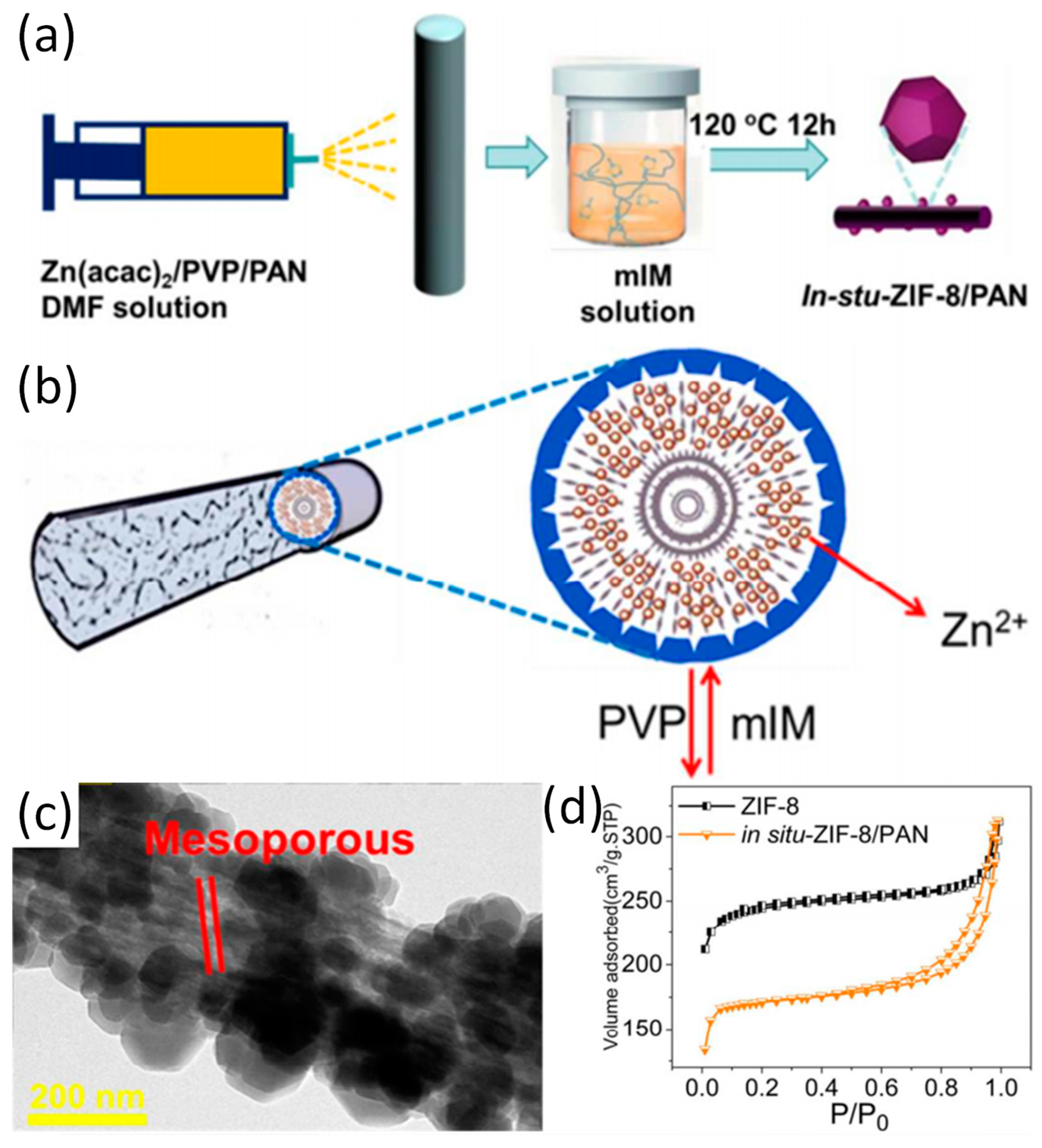
First of all, the preparation of zeolitic imidazolate framework-8 (ZIF-8)/polyacrylonitrile (PAN) nanofibers is introduced as a model M-NFs by in situ growth method (Ⅰ) was highlighted [14]. Specifically, as depicted in Figure 1a, zinc acetylacetonate (Zn(acac)2), PAN, and poly-(vinylpyrrolidone) (PVP) are mixed in N,N-Dimethylformamide (DMF) to obtain an electrospun precursor solution. Then Zn(acac)2/PVP/PAN fibers are prepared by electrospinning immediately followed by immersion in mixed with 2-methylimidazole (mIM) solution within a Teflon-lined container and kept at 120 °C for 12 hours. Because PVP is more hydrophilic than PAN, PVP can be extracted from Zn(acac)2/PVP/PAN fibers in accompany by the generation of pore structure by hydrothermal treatment (Figure 1b). It was shown that ZIF-8 nanocrystals grow tightly on the surface of PAN nanofibers. The mesoporous structure of in situ-ZIF-8/PAN is displayed on the surface of nanofibers during in situ growth process, which may be attributed to the removal of PVP (Figure 1c). Interestingly, a typical behavior of type IV hysteresis loop as shown in Figure 1e validates the existence of mesopores on ZIF-8/PAN fibers. Recently, mIM/PAN nanofibers have been prepared by electrospinning and subsequent chelating with Zn2+ ions provided by zinc acetate, leading to the formation of core–shell PAN@ZIF-8 [35]. Addition of mIM and zinc acetate solution during in situ growth can promote the further growth of ZIF-8 nanocrystals. Moreover, the core–shell structure of the composite displays high toughness due to the support of underlying PAN nanofibers. With regard to the in situ growth method in obtaining Z-NFs, organic ligand/polymer NFs or metal ion/polymer NFs are prepared first, and then the ZIFs crystal grows on the respective NFs.
Apart from in situ-grown ZIF-8/PAN, other types of Z-NFs prepared have been prepared by in situ growth method. Zhou and co-workers reported the first time in situ crystal growth of ZIF-8 on electrospun polyurethane (PU) nanofibers (ZIF-8/PU) [34]. More specifically, the surface of PU nanofibers were roughened by the treatment with concentrated sulfuric acid and chromic anhydride, exposing more binding sites on the nanofiber surface. For instance, the emergence of anionic groups on the surface of PU nanofiber facilitates the adsorption of Zn2+, which serves as the coordination center of the ZIF-8 nanocrystal to be eventually distributed in high concentration on the PU nanofibers. Moreover, BET surface area of ZIF-8/PU decreases with the amount of ZIF-8 nanocrystal. Although the loading of the MOFs nanoparticles was increased by activating the surface of the fiber and the like, which brought about an occlusion of the pores and attenuate the adverse effects of the one-dimensional morphology of the nanofibers. Therefore, it is not advisable to increase the load blindly, various factors such as the ‘bearing capacity of the nanofibers’ should be comprehensively considered in the preparation of M-NFs.
In addition to pre-treating the materials during in-situ growth to optimize the structure of the M-NFs, different metal sources can also be used to obtain different structures and performances. Different types of materials can be selected as the source of metal ions or as templates for the growth of ZIFs crystal. By introducing other materials into the crystal growth process, a variety of composites with unique structures and physical properties can be obtained. Activation of the fiber surface and continued addition of ligand or metal ion solution during in situ growth can promote the ZIFs crystal growth. When In2O3/ZnO2 nanofibers instead of Zn2+ coated PU nanofiber was applied as a source of Zn2+ for serving as a template for the in situ growth of ZIF-8, an In2O3/ZIF-8 core–shell complex was successfully produced with the effective loading of ZIF-8. It is also noteworthy that the transformation from ZnO particles to metal centers coordinated with organic ligands may likely lead to the formation of structural defects between linkers, thus enlarging the pore size of metal–organic framework ZIF-8 [36,37]. In addition, the transformation as mentioned above can cause ZIF-8 to form multiple pore structures.
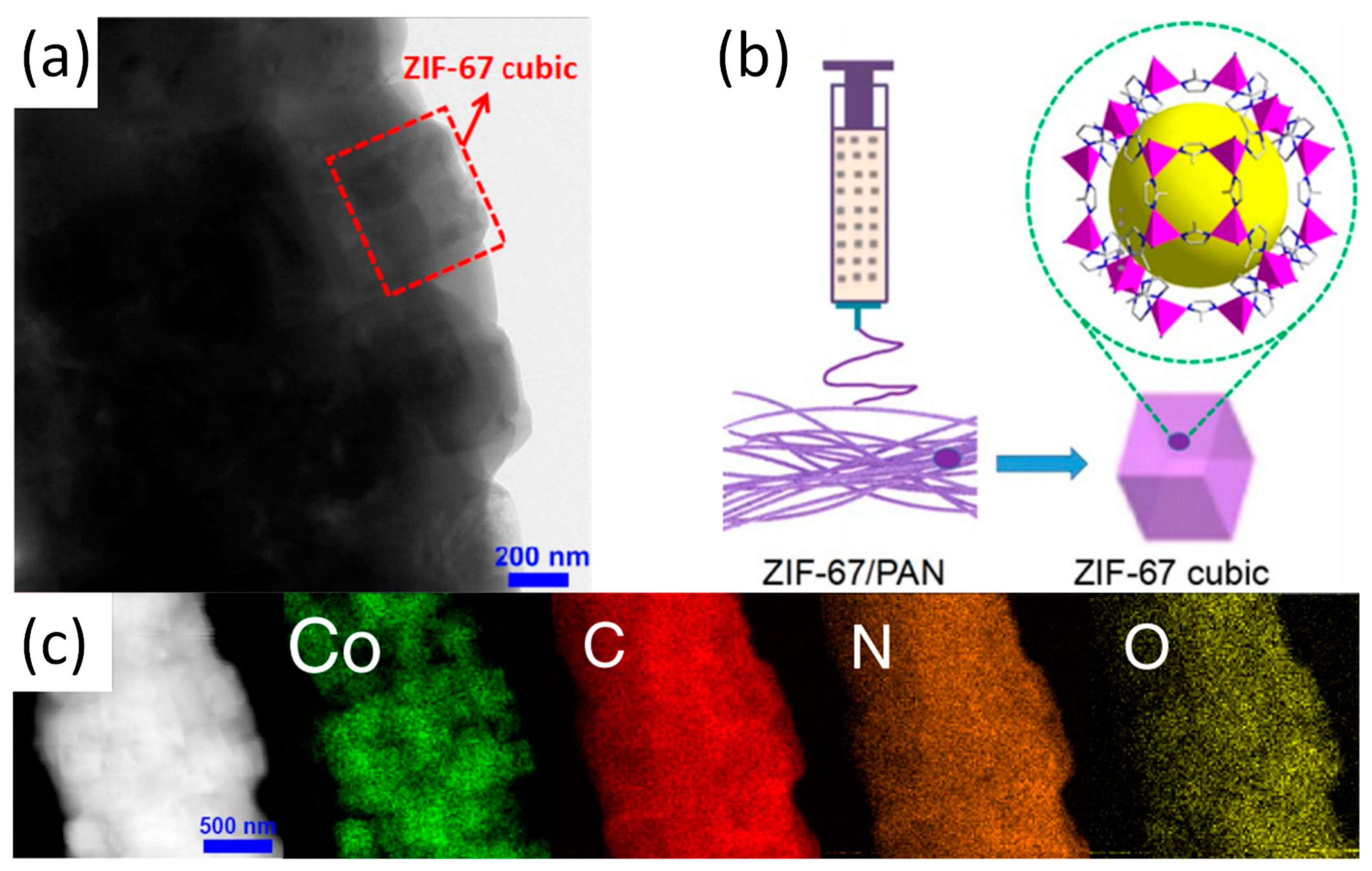
While the in situ growth method is being developed, another method known co-electrospinning has received increasing attentions. Again, ZIF-67/PAN is used as a typical example to cover the co-electrospinning method in detail [38]. Schematic diagram, TEM image and the corresponding elemental mapping of ZIF-67/PAN as shown in Figure 2. After the synthesis of ZIF-67 nanoparticles, the nanoparticles were mixed with PAN to form an electrospun precursor solution and ZIF-67/PAN nanofiber was fabricated by electrospinning. When the ZIF-67/PAN are applied to the catalytic degradation of pollutants, the high specific surface area of the ZIF/PAN can promote effective contact between active sites and pollutants. Random arrays and macroscopic materials with continuous specific surface area and flexibility are also promotive to the recovery and reuse of catalysts [39]. In addition to the most common only used PAN and PVP, the use of other polymers such as polyethylene oxide (PEO) and polystyrene (PS) has improved the fiber stability and expanded the range of possible applications. Previously, Smarsly and co-workers have reported on ZIF-8/PVP nanofibers, which was prepared by co-electrospinning [33]. Table 1 lists the BET surface area of the nanofibers formed by the combination of ZIF-8 and different types of polymer. The co-electrospinning method enables ZIFs nanoparticles to be uniformly loaded on electrospun fibers. It is worth noting that the co-electrospinning method imposes design constraints on the selection of ZIFs within a specific range of size. If ZIFs is too large compared to the electrospun fibers with dimension of several hundred nanometers, it would result in the ineffective encapsulation of ZIF by the electrospun fiber matrix and nonuniform dispersion of the particles on the fiber matrix. Comparatively, the ZIFs particles with appropriate size would be evenly dispersed in the electrospun solution before electrospinning to ensure uniform loading of the particles on electrospun fibers. Regardless of the method route of synthesis of the Z-NFs, it has the following characteristics in general:
- (a)
- ZIFs nanoparticles are evenly loaded in the fiber matrix and the degree of loading is adjustable, which effectively avoid the large-scale agglomeration of ZIFs nanoparticles;
- (b)
- Defects, mesopores, etc. can be formed during electrospinning;
- (c)
- Nanofibers can enhance the mechanical properties and stability of Z-NFs due to its support and protection of ZIFs nanoparticles.
2.2. Other Types of M-NFs
Z-NFs is not only the most representative type of material in M-NFs, but also the earliest and most widely studied materials. With the development of Z-NFs, more MOF materials other than sole ZIFs have been produced through the fabrication of nanofiber composites by electrospinning (in the rest of the article, M-NFs only refers to other types of M-NFs except Z-NFs). M-NFs are prepared in a similar way compared to Z-NFs, while larger range of structural and physical properties of M-NFs are revealed, due to the significant variability among different metal centers and organic ligands [40,41,42,43,44,45,46,47].
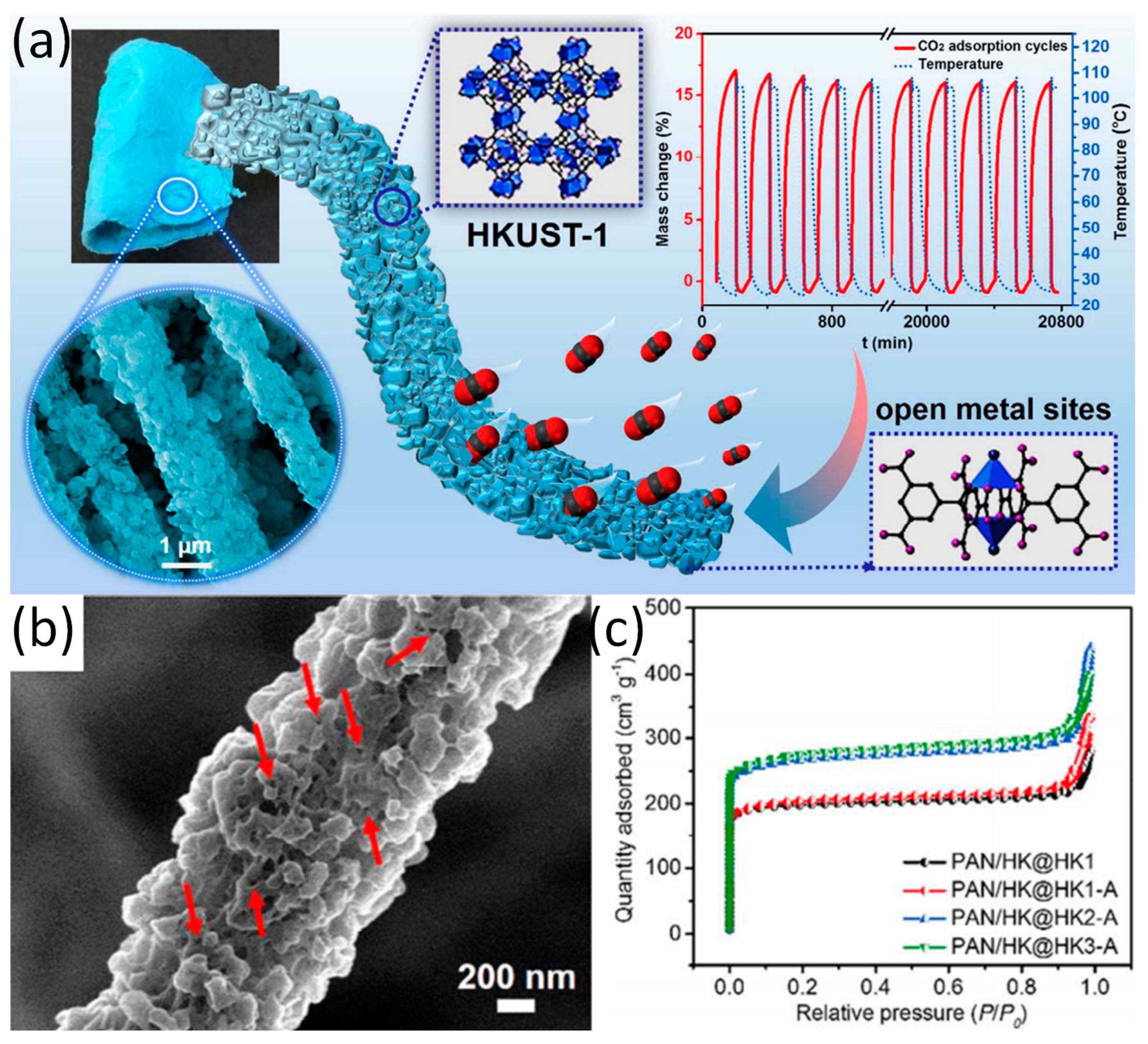
The preparation methods of ZIFs are simple and the preparation conditions are mild. However, the preparation conditions of MOFs such as HKUST-1 are complicated. Thus, the preparation of such M-NFs has a variety of methods. For instance, Wang and co-workers have prepared a new type of M-NFs known as HKUST-1 (Cu-MOF)/PAN nanofibers by combining co-electrospinning and in situ growth, which promoted multiple growth and activation processes [40]. The active site of CO2 adsorption on the HKUST-1/PAN nanofibers are mainly at the open metal sites (Figure 3a). The as-synthesized HKUST-1 particles and HKUST-1/PAN NFs readily exhibits polydisperse microporous characteristics (Figure 3b). As shown in Figure 3c, the BET surface area of the HKUST-1/PAN NFs increase significantly due to the increase of the loading of HKUST-1 nanoparticles after three times of growth and activation. Interestingly, the multiple growth and activation processes during the preparation of HKUST-1/PAN nanofibers with high HKUST-1 can promote the effective integration between coordinated unsaturated metal sites and uncoordinated –COO- within frameworks [48]. In addition, the membranous HKUST-1/PAN nanofibers solves the problem of pipeline blocking and recovery inefficiency during the adsorption process as the nanofiber is less susceptible to powder and display less tendency to form agglomerate [49,50].
Multiple activations and growths can enhance the loading of MOF nanoparticles and the binding force of MOF particles and nanofibers to obtain more stable and more active composites. Besides, similar performance can be achieved by selecting the appropriate polymer with a target group which can form a strong bonding with the organic functional groups or ions in MOFs. Recently, Peng and co-workers have reported a UiO-66/PVA (polyvinyl alcohol) nanofiber networks via co-electrospinning [41]. The hydroxyl groups (-OH) in PVA and the carboxylic acid groups (-COOH) in UiO-66 could be esterified during the electrospinning process to form ester bonds, which facilitates the formation of interwoven nanofiber networks. Moreover, the nanofiber networks can improve the wettability of materials in the electrolytes when it is applied as battery materials [51]. It is tough to fabricate independent MOF–organic matrix composites with high MOF-loading capacity by general preparation method. Recently, Wu et al. have reported the fabrications of HKUST-1/PS (polystyrene) and MIL-101(Fe)/PS via co-electrospinning when most MOF particles are encapsulated within the fibers during electrospinning [42]. Only when MOF particles with high loading enough are exposed to the surface of the fibers, the carrying of gas and the transfer of electron can be facilitated for the materials. However, adding high load of MOF particles will reduce the suitability of polymer solutions for use in electrospinning. In addition, with the increase of MOF loading during electrospinning, it is difficult to obtain compact and continuous MOF films. By using MOF-doped electrospun nanofibers as the skeletal backbone, the growth of second MOF layer on the fibers can overcome the existing difficulties [42]. In short, the problems of preparing M-NFs can be resolved by a combination of co-electrospinning and in situ growth.
The polymers related to M-NFs which were reported in recent years are mainly PAN, PVP, PVA, PS, etc. However, many other polymers (such as PVDF, PA, PEO, etc.) are also important materials for preparing M-NFs. Laurila et al. reported the in situ crystal growth of HKUST-1 on electrospun cellulose nanofibers [52]. Yang et al. also reported on a composite material, which was composed of cellulose paper and MOF-5 (Zn3(BDC)2) metal organic frameworks (paper@MOF-5) materials [53]. Zhao et al. reported that TiO2 coatings deposited on polyamide-6 (PA-6) nanofibers by atomic layer deposition (ALD) to form Zr-based MOF thin films (PA-6@TiO2@UiO-66-NH2). Moreover, certain MOF–nanofiber textile composites can achieve ultra-fast degradation of chemical warfare agents (CWAs) [54]. Wu et al. reported that electrospun nanofiber membrane composed of MOFs and SPPESK was applied in proton exchange membrane fuel cell [55]. Recently, Xu et al. reported on the application of ZIF-8 functionalized hierarchical micronanofiber membrane (PVDF-g-ZIF-8) in high-efficiency oil/water separation [29]. Rosal and co-workers presented polylactic acid (PLA) fibers containing cobalt-based MOF as a new class of antimicrobial film material [31]. Similarly, Shariatinia and co-workers reported on the synthesis of antimicrobial chitosan–polyethylene oxide (CS-PEO) nanofiber mats loaded with ZIF-8 NPs via electrospinning [56]. Table 2 lists the application performances or properties of different types of MOF/electrospun nanofibers in recent years.
3. Electrospun MOFs-Derived Carbon Nanofibers
3.1. Synthesis
Electrospun MOFs-derived carbon nanofibers (M-CNFs) are generally prepared by heat treatment and reduction of M-NFs that obtained via electrospinning. After M-NFs are obtained, the heat treatment of composites can be roughly classified into two categories:
(I) The composites are directly subjected to high temperature carbonization under an air atmosphere to obtain a target product (direct calcination method). The structure and properties of the target product can be controlled by changing the temperature, heating rate, and calcination time.
(II) Preheating the composites in an air atmosphere at lower temperature and then transferring the composites to high temperature carbonization under N2 (or Ar) atmosphere (indirect calcination method).
In the direct calcination method, pure phase metal oxides can be obtained at higher temperatures. Recently, Kim and co-workers have reported that the as-spun Pd@ZIF-8/PVP/Sn composite NFs were transformed to PdO@ZnO-SnO2 NTs after the calcination at 600 °C for 1 h in air atmosphere under the heating rate of 10 °C min−1 [61]. Some polymer fibers (such as PAN) are easily decomposed at high temperatures, causing the damage to the fiber structure. Therefore, in the indirect calcination method, before the calcination of samples at high temperature, the samples are preheated and oxidized first to remove some heat-labile organic functional groups to ensure the integrity of the nanofiber network structure. For instance, Guo et al. reported the obtention of the Co/CoOx-N-C via the pyrolysis process that includes stabilization and carbonization. The progress of stabilization was implement in air at 280 °C for 2 h. Carbonization step was conducted in a N2 atmosphere at temperature up to 800 °C for 1 h [62].
3.2. Application
The wide application of M-CNFs is attributed to its attractive structures such as one-dimensional nanofibrous morphology and hollow tubular structure. MOFs-derived carbon nanofibers have been considered as excellent electrode materials in energy conversion and storage devices [63,64,65]. Moreover, catalysis and sensors are also the main applications of M-CNFs. Typical applications (e.g., battery, sensor, and electrocatalyst) of materials are presented and analyzed.
3.2.1. Battery
• Lithium/sodium ion battery
The difference in physical properties of electrode material directly affects the performance of the battery. Poor battery performance is mainly attributed to two aspects: (1) Its extremely low intrinsic electrical conductivity; (2) Volume expansion of the material during charging/discharging, which causes particle comminution and spalling [66]. Many studies have focused on the development of electrode materials with high specific capacity, good rate performance and stability. For instance, Yi et al. reported on a Mn3O4/graphene composites as electrode of battery [67]. Although the material has high reversible capacity and current density, due to the high surface energy and van der Waals forces, irreversible overlap and condensation of graphene nanosheets easily occur during charging and discharging. Wang et al. reported that preparation of carbon-coated manganese oxide (Mn3O4@C) via solvothermal reaction of manganese acetate monohydrate and polyvinylpyrrolidone [68]. However, the active material is encapsulated in carbon during solvothermal process, which will result in a reduced contact interface between the active material and the electrolyte. M-CNFs as a new class of carbon materials have received more and more attention due to their outstanding performance, and the supporting effect of the carbon nanofiber networks on the system can improve the resistance of the composite towards volume change. Moreover, the carbon nanofiber networks can uniformly load the MOF nanoparticles, which increase the contact area between the composite and the electrolyte. For instance, Yang et al. a porous Co3O4 with electrospun carbon (Co3O4/C) prepared by annealing the ZIF-67/PAN templates, the Co3O4/C shows a capacity of 1024.1 mAh g −1 after 100 cycles [69].
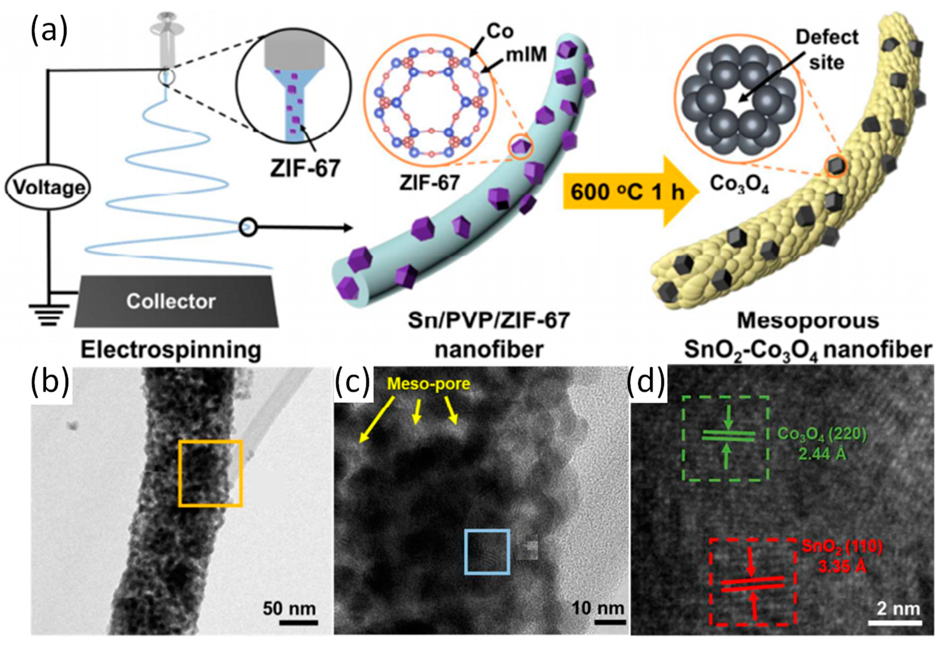
Electrospun MOFs-derived one-dimensional carbon nanofibers are ideal materials for battery electrode materials due to their high specific surface area, good electrical conductivity, and well-defined porous structure. For instance, Cheong et al. have prepared one dimension SnO2-Co3O4 NFs with ZIF-67 (which contains Co ions and mIM) as a template [70]. Schematic illustration of synthesis of SnO2-Co3O4 NFs are shown in Figure 4a. The one-dimensional SnO2-Co3O4 NFs was formed via electrospinning and subsequent calcination process form a large number of mesoporous structures. The results shows that the introduction of the ZIF-67 framework not only causes the material to form a large number of oxygen vacancies, but also enhances the conductivity of the material, inducing more active sites for Li storage in lithium-ion batteries (LIBs). As such SnO2-Co3O4 NFs maintain a reversible capacity of 1287 mAh g−1 after 300 cycles at a current density of 500 mA g–1. Similarly, the authors have prepared hollow porous SnO2-CuO composite nanotubes by electrospinning and calcination [71]. After the introduction of the MOF framework as a template and co-electrospinning with polymers, the formed SnO2-MxOy (metal oxide) nanocomposites (nanofibers) display a porous (mesoporous) structure as well as a large number of defects and oxygen vacancies, which solves the problems of poor cycle stability, low ionic conductivity, and low reversible capacity of SnO2. In addition to the introduction of MOF framework into SnO2 system by electrospinning and heat treatment to form SnO2-MxOy porous nanofibers, many reports have focused on the formation of metal oxide/carbon nanofibers composites formed by co-electrospinning of MOF nanoparticles and polymer and the subsequent heat treatment as electrode materials for batteries. Yang et al. have reported a yolk–shell MnOx carbon nanofiber composite (ysMnOx@NC) based on Mn-MOF [72]. The yolk–shell structure of the material can be seen from the Figure 5d. The structure can accommodate volume changes during material cycling and reduce loss of activity. It is shown that ysMnOx@NC retains great activity even after 1000 cycles (current density of 2 A g−1). Double buffering of nanofibers and the yolk–shell structure can reduce the activity due to material loss during cycling, thereby increasing the reversible capacity of the battery.
Preparing materials with special structure (porous or yolk shell structures) is a way to improve the performance of M-CNFs as battery materials. Besides, preparation of bimetallic or polymetallic composite materials is also an important method to optimize the performance of M-CNFs. The improvement in performance is mainly due to the synergy between bimetallic or polymetallic. Sodium-ion batteries (SIBs) are also of much interests. Recently, Li and co-workers have reported a kind of hierarchical heteroatom-doped carbon nanofibers decorated with several nanocomposites (NiCo2O4/NiO/carbon nanofibers) based on Co/Ni-ZIF, which was prepared via successive carbonization and oxidation heat-treatments [73]. One-dimensional carbon nanofibers are intertwined by the MOF framework to form a 3D conductive matrix, and uniform dispersion of the active material therein can also improve electrical conductivity and cycle stability. The material showed a high sodium storage capacity of up to 210 mAh g−1 after 200 cycles (100 mA g−1). Zhang et al. have also prepared carbon fibers with uniformly distributed Co3O4 hollow nanoparticles (NPs) by electrospinning of ZIF-67 NPs and thermal treatment [74].
To sum up, typical composite materials are generally obtained by using the MOF as a template via electrospinning and the subsequent heat treatment or reduction process. When the material is applied to the LIBs and SIBs, the performance is improved mainly for the following reasons:
(a) The MOF framework will form excess oxygen vacancies and defects, thereby increasing the active site of the material during post-treatments;
(b) The porous interwoven network of MOF derivative carbon nanofiber can improve the mass/charge transport and the conductivity of the material, support the composite system, and adapt the cyclic change of the material to reduce the loss of activity of the material for achieving high lithium (sodium) storage capacity;
(c) Synergistic interaction between polymetallic and between metal and carbon nanofiber networks can improves material performance;
(d) Anisotropic materials with hollow and porous structures have large specific surface area and strong carrying capacity.
• Metal-air battery
Zn-air battery is the most widely studied and used battery in the metal-air battery category. MOFs are considered as a suitable material for Zn-air battery due to its tunable structure and inherent heteroatoms that promote electron transfer. However, MOF-derived carbon catalysts are generally susceptible to evolution into isolated nanoparticles, which greatly reduces conductivity and thus weakens its electrochemical properties. One-dimensional porous conductive networks of carbon nanotubes or carbon fibers have been shown to improve the conductivity and electron transfer of materials, which has aroused widespread interest among researchers. It is worth mentioning that composite materials like M-CNFs with hierarchical structure and hybrid nanostructures provide additional channels for material diffusion, promoting exposure of active reactive sites [75].
3.2.2. Supercapacitor
According to different energy storage mechanisms (SCs), supercapacitors can be divided into two categories: electric double layer capacitors (EDLCs) and Faraday quasi capacitors. EDLCs has received much attention for its outstanding advantages [76]. Carbon materials with a porous structure and a large surface area are necessary to improve the performance of EDLCs. Among the conventional carbon materials—including carbon nanotubes [77], graphene [78,79], and carbon nanofibers (CNFs) [80,81]—many of them have been widely used as electrodes for EDLCs. Kim et al. reported a carbon materials with a high specific surface (1453 m2 g−1) by activated carbon fiber prepared [82] The introduction of nitrogen not only increases the energy density of the composite but also promotes the conduction of electrons [82,83]. M-CNFs are well suited for application as supercapacitor electrode materials because of their large specific surface area with abundant pore structure and inherent N-doping. For instance, Yao et al. reported the nitrogen-enriched hierarchical porous carbon nanofibers (NHCFs) prepared by electrospinning the composite of ZIF-8 and PAN, and at a current density of 40 A g−1, the specific capacitance was maintained at 146.7 F g−1 [84]. Recently, the author also reported on the N-doped graphitic hierarchically porous carbon nanofibers which were obtained by electrospinning a composite of bimetallic organic framework (Zn/Co-MOF) and polyacrylonitrile. The Zn/Co-MOF-based carbon nanofibers exhibited a high capacitance of 326 F g−1 at 0.5 A g−1 [85].
3.2.3. Sensor
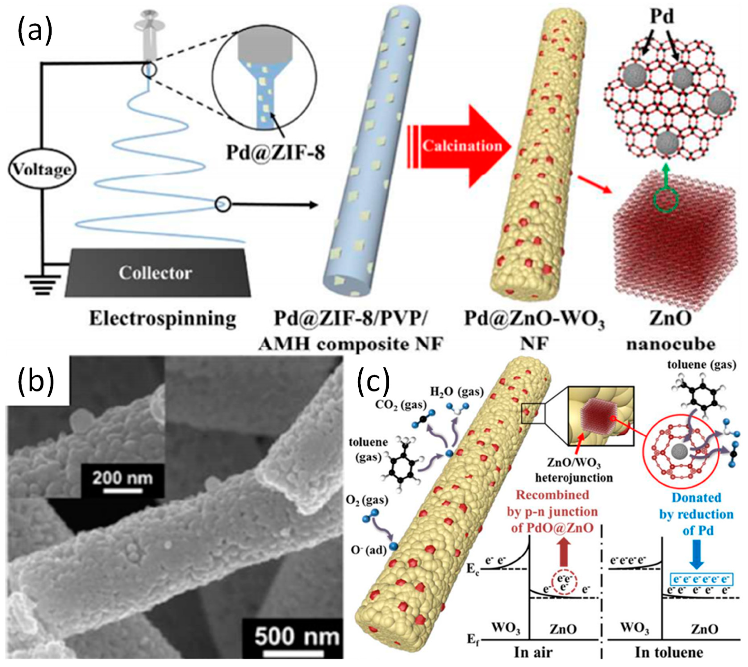
Nowadays, air pollution is getting more serious, the monitoring of volatile organic pollutants such as acetone is receiving more attentions. MOFs have many attractive features, including the ability to encapsulate precious metal nanoparticles (metal@MOF) [86]. Hermes et al. have reported that metal organic chemical vapor deposition was used to release metal atoms from precursor and penetrate metal atoms into MOFs [87]. Jiang et al. synthesized the NPs@ZIF-8 coated with nanoparticles via sequential deposition and reduction of metal precursors [88]. However, the application of these methods is limited by the relatively poor chemical stability of MOF, which is mainly attributed to thermal instability of organic ligand in MOFs. It is worth noting that the heterojunction formed between the carbon nanofibers and the active material from MOF, which can improve the stability of the composite. Moreover, the reduced clustering of precious metal nanoparticles in composite nanofiber matrix can improve the sensing performance of the material. In addition, electrospinning functionalizes catalysts onto one-dimensional nanofibers to provide high specific surface area and high gas accessibility as required for high performance chemical sensors [89]. For instance, Koo et al. have reported on the heterogeneous sensitization of metal-embedded metal oxide (M@MO) composite catalysts driven by MOF on semiconductor metal oxide (SMO) nanofibers (NFs) via electrospinning and calcination [90]. During calcination, metals are oxidized to a metal oxide while the framework of the MOFs remains and the nanoparticles are fixed onto the framework. Electrospinning enables the immobilization of 3D M@MO composites on a one-dimensional fiber, leading to the development of high performance chemical sensors with high specific surface area and excellent gas accessibility. In addition, M@MO composites act as synergistic catalysts due to the heterojunctions between metal oxide frame and the SMO NFs. Preparative process diagram of the Pd@ZnO-WO3 NFs is shown in the Figure 6a. TEM images of the samples are shown in the Figure 6b, and inset is its high magnification TEM image. Pd@ZIF-8 particles are embedded on the surface of ammonium metatungstate hydrate (AMH)/PVP NFs and composite NFs. Dual heterogeneous multi-junctions appears on the interface between Pd-ZnO and ZnO-WO3 via electrospinning, which promotes electron conduction and sensing performance of Pd@ZnO-WO3 NFs. Kim and co-workers have conducted further research on the basis of this work and prepared the PdO@ZnO dual catalysts-loaded hollow SnO2 NTs (PdO@ZnO-SnO2 NTs) via electrospinning and the subsequent calcination [61]. The hollow structure in PdO@ZnO-SnO2 NTs can ensure the uniform loading of a large amount of precious metal particles, and the active sites are also increased correspondingly. The hollow PdO@ZnO-SnO2 NTs exhibited high acetone response (Rair/Rgas = 5.06 at 400 °C@1 ppm). Guo et al. have prepared the Pt-ZnO-In2O3 composite nanofibers with ZIF-8 as a template by electrospinning [91]. The excellent acetone gas sensing property of Pt-ZnO-In2O3 NFs is related to the n-n heterojunctions between ZnO and In2O3 and p-n heterojunction formed between p-type PtO2 and n-type In2O3 (ZnO). Precious metal particles can be uniformly dispersed in the network structure formed by electrospun nanofibers and MOF frames, which can effectively solve the deterioration of sensing performance caused by agglomeration of metal particles. After heat treatment, a variety of heterojunctions formed in the material can enhance the conductivity and the synergy among the metal oxides, and a large number of oxygen vacancies can improve the sensing performance.
3.2.4. Electrocatalyst
Fuel cells are receiving more attentions with the development of clean energy technologies [92,93]. In general, oxygen reduction reaction (ORR) plays a key role in fuel cells, metal-air batteries, and water decomposition [94]. Pt and its alloys are considered to be the most effective ORR electrocatalyst at present, but their high cost and poor stability stimulate the increasing interests to develop new materials as potential replacements [95]. However, the materials currently developed still possesses the disadvantages such as low conductivity, environmental pollution, and unsatisfactory performance. Electrospinning is an important method for preparing carbon nanofibers with large specific surface area, good electrical conductivity, excellent mechanical strength, and good chemical stability [96]. MOFs are precursors and templates that are well suited for the preparation of porous carbon materials. Thus MOF-derived carbon-based materials have attracted increasing attention in ORR catalysis due to their adjustable structure, and porous characteristics. Due to the importance of the inherent transition metals or heteroatoms, the performance of electrospun MOF-derived electrocatalysts can be optimized by selecting suitable metal (or metal cluster) centers and organic ligands. For instance, Niu et al. have designed Zn-Co bimetallic nitrogen doped hollow carbon nanofiber composite for ORR application [97].
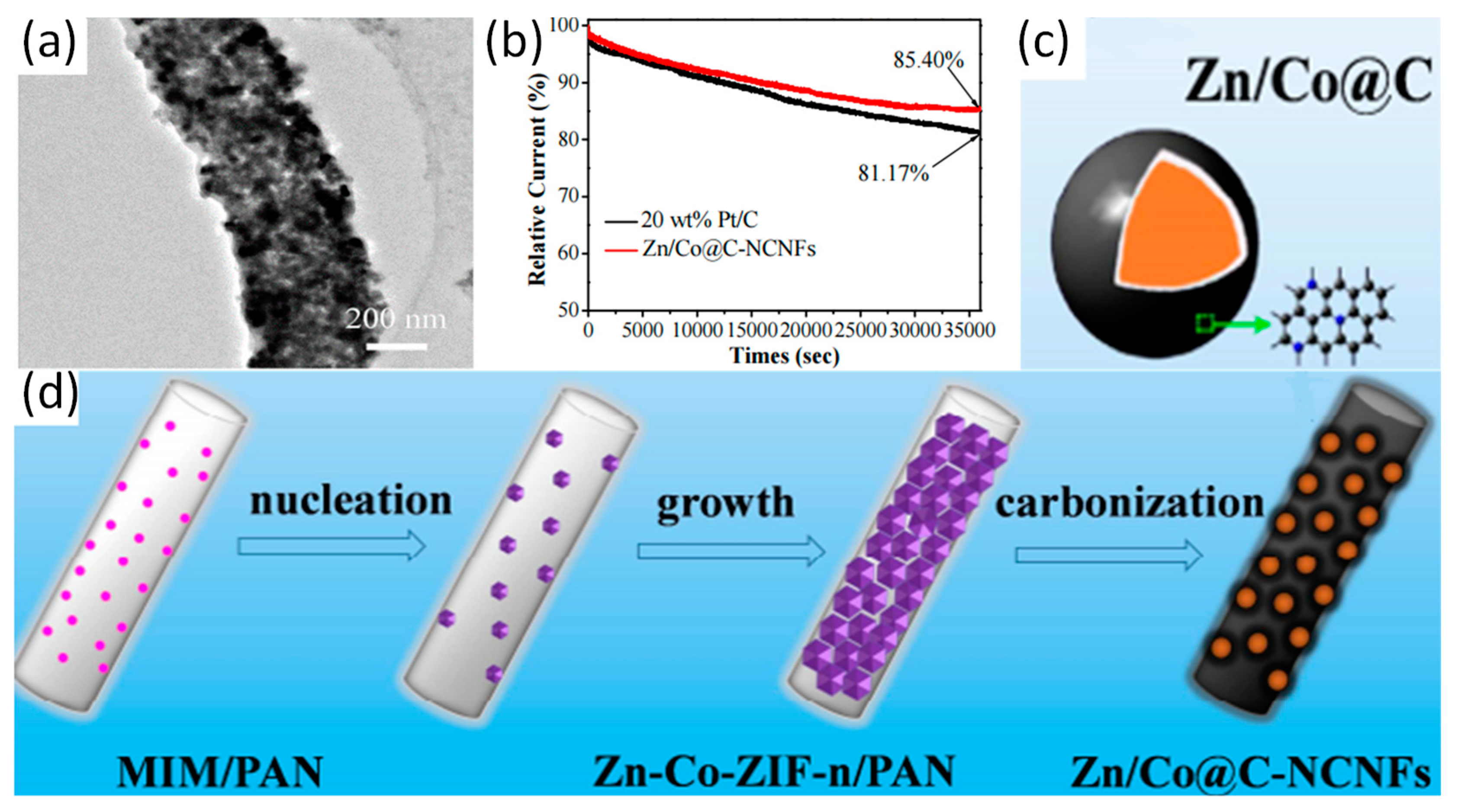
Bimetall zeolitic imidazolate frameworks (ZIFs) grown on the surface of MIM/PAN electrospun nanofibers via electrospinning, that is Zn-Co-ZIF-n(shell)/PAN(core) nanofibers (n refers to the molar ratio of Zn/Co before carbonization). After subsequent calcination, Zn/Co@C-NCNFs with layered network structure and high surface area are prepared, whose core layer is nitrogen-doped carbon nanofibers (NCNFs) and the shell layer is Zn/Co bimetallic nanoparticles coated with graphitic carbon layer (Zn/Co@C). Preparative process of Zn/Co@C-NCNFs is shown in Figure 7d. The diameter of the nanofibers gradually increases, which is corresponding to the growth process of nanofibers. The results illustrate that metal ions and organic ligands nucleate by coordination and grow on nanofibers. As the particles are limited by the surface of the fiber during growth, the smaller particle can be obtained easily. Moreover, Zn/Co@C-NCNFs displays core–shell nanofiber structure with dual active centers, and the formation of the graphitic layer in Zn/Co@C-NCNFs are beneficial to the conduction of electrons. The result showed that the duration stability of the Zn/Co@C-NCNFs was far better than that of the commercially available 20 wt % Pt/C (Figure 7b). Graphite carbon formed by carbonization can significantly improve the conductivity of materials. In addition, doped N combines with graphite carbon under high-temperature carbonization, and the formation of mesoporous structure can enhance the electrochemical properties of the material. Guo et al. have reported a novel pod-like nitrogen-doped carbon fibers encapsulated with cobalt/cobalt oxide nanoparticles (Co/CoOX-N-C), which were prepared by electrospinning and carbonization with ZIF-67 used as a template [62]. The Co/CoOX-N-C exhibited excellent discharge specific capacity (610 mAh g−1) and discharge voltage, which are comparable to 20 wt % Pt/C and RuO2. Moreover, Wu et al. have reported that hierarchical porous Fe-N-doped carbon nanofibers (Fe-NHCFs) can be fabricated via carbonization of MOF nanofibers [98]. Fe-N doping induces a large number of active sites to enhance the electrocatalytic activity of materials. Parallel characteristics with Pt/C is obtained in an assembled Zn-air battery, which provides a discharge current density of 90 mA cm−2 and an output peak power density of 61 mW cm−2. Application performances or properties of representative electrospun MOF-derived carbon nanofibers are shown in Table 3.
MOF-derived carbon-based materials doped with heteroatom can exhibit electrocatalytic properties comparable to those of Pt, which mainly due to the following aspects:
(a) The inherent MOF framework and pore canals formed by interweaving the electrospun fibers with the organic framework during the carbonization process provide additional channels for O2 in the system (promoting mass transfer);
(b) Highly graphitized and one-dimensional porous conductive networks improve the conductivity and electron transfer of materials;
(c) Metal-heteroatom doping in the system induces the formation of a large number of active sites.
4. Summary and Outlook
Due to the existence of heterojunction between MOF nanoparticles and nanofibers, the stability of the materials are enhanced while active sites are increased in number. In addition, the anxiety regarding the difficulty of recycling and easy agglomeration of the nanoparticle can be relieved with the adoption of the electrospun fibers support. After calcination, the mesoporous structure, defects and oxygen vacancies may be formed in the electrospun MOF-derived nanomaterials (mainly referring to the materials after heat treatment), which is beneficial for the improvement of the performance of the obtained composite nanofibers. However, further efforts in the field are still needed to address the following issues:
(1) For M-NFs composite materials: (a) the activity and specific surface area of the material decrease compared to their constituent MOFs nanoparticles; (b) The loading of MOFs particles in the electrospinning method is less controllable and the stable growth of MOFs particles on the fibers is hard to be achieved during in situ growth process.
(2) For the electrospun MOF-derived nanomaterials, the mechanical properties of the fibers after heat treatment are significantly reduced, hindering its further application.
(3) More research should focus on the relationship between performance and structure. In other words, M-NFs and their derivatives obtained by electrospinning have great potential in many emerging applications.
Author Contributions
Investigation, M.L. and N.C.; Resources, V.C. and F.Y.; Writing—original draft preparation, M.L.; Writing—review and editing, M.L., N.C., and V.C.
Funding
This research was supported by National Natural Science Foundation of China (21571147, 51808414), Natural Science Foundation of Hubei Province (2018CFB108), Hubei Collaborative Innovation Center for Down-Streaming Products in Ethylene Project and Process Intensification, Outstanding Young and Middle-aged Scientific Innovation Team of Colleges and Universities of Hubei Province: "Biomass chemical technologies and materials" (Grant No. T201908) and Graduate Innovative Fund of Wuhan Institute of Technology (CX2018002). V.C. acknowledges the financial support of Khalifa University of Science and Technology through CIRA-2018-02.
Conflicts of Interest
The authors declare no conflict of interest.
References
- Furukawa, H.; Cordova, K.E.; O’Keeffe, M.; Yaghi, O.M. The chemistry and applications of metal-organic frameworks. Science 2013, 341, 1230444. [Google Scholar] [CrossRef] [PubMed]
- Li, B.; Wen, H.M.; Cui, Y.; Zhou, W.; Qian, G.; Chen, B. Emerging multifunctional metal-organic framework materials. Adv. Mater. 2016, 28, 8819–8860. [Google Scholar] [CrossRef] [PubMed]
- Lee, J.; Farha, O.K.; Roberts, J.; Scheidt, K.A.; Nguyen, S.T.; Hupp, J.T. Metal-organic framework materials as catalysts. Chem. Soc. Rev. 2009, 38, 1450–1459. [Google Scholar] [CrossRef] [PubMed]
- Chen, Y.; Huang, X.; Zhang, S.; Li, S.; Cao, S.; Pei, X.; Zhou, J.; Feng, X.; Wang, B. Shaping of metal–organic frameworks: From fluid to shaped bodies and robust foams. J. Am. Chem. Soc. 2016, 138, 10810–10813. [Google Scholar] [CrossRef] [PubMed]
- Furukawa, H.; Ko, N.; Go, Y.B.; Aratani, N.; Choi, S.B.; Choi, E.; Yazaydin, A.Ö.; Snurr, R.Q.; O’Keeffe, M.; Kim, J. Ultrahigh porosity in metal-organic frameworks. Science 2010, 329, 424–428. [Google Scholar] [CrossRef] [PubMed]
- Chen, Y.; Zhang, S.; Cao, S.; Li, S.; Chen, F.; Yuan, S.; Xu, C.; Zhou, J.; Feng, X.; Ma, X.; et al. Roll-to-Roll Production of Metal-Organic Framework Coatings for Particulate Matter Removal. Adv. Mater. 2017, 29, 1606221. [Google Scholar] [CrossRef] [PubMed]
- Qiu, S.; Xue, M.; Zhu, G. Metal-organic framework membranes: From synthesis to separation application. Chem. Soc. Rev. 2014, 43, 6116–6140. [Google Scholar] [CrossRef]
- Li, J.R.; Kuppler, R.J.; Zhou, H.C. Selective gas adsorption and separation in metal-organic frameworks. Chem. Soc. Rev. 2009, 38, 1477–1504. [Google Scholar] [CrossRef]
- Li, X.; Liu, Y.; Wang, J.; Gascon, J.; Li, J.; Van der Bruggen, B. Metal-organic frameworks based membranes for liquid separation. Chem. Soc. Rev. 2017, 46, 7124–7144. [Google Scholar] [CrossRef]
- Lustig, W.P.; Mukherjee, S.; Rudd, N.D.; Desai, A.V.; Li, J.; Ghosh, S.K. Metal-organic frameworks: Functional luminescent and photonic materials for sensing applications. Chem. Soc. Rev. 2017, 46, 3242–3285. [Google Scholar] [CrossRef]
- Pan, Y.; Xue, M.; Chen, M.; Fang, Q.; Zhu, L.; Valtchev, V.; Qiu, S. ZIF-derived in situ nitrogen decorated porous carbons for CO2 capture. Inorg. Chem. Front. 2016, 3, 1112–1118. [Google Scholar] [CrossRef]
- Ahn, Y.; Park, S.; Kim, G.; Hwang, Y.; Lee, C.; Shin, H.; Lee, J. Development of high efficiency nanofilters made of nanofibers. Curr. Appl. Phys. 2006, 6, 1030–1035. [Google Scholar] [CrossRef]
- Wang, C.; Kaneti, Y.V.; Bando, Y.; Lin, J.; Liu, C.; Li, J.; Yamauchi, Y. Metal–organic framework-derived one-dimensional porous or hollow carbon-based nanofibers for energy storage and conversion. Mater. Horiz. 2018, 5, 394–407. [Google Scholar] [CrossRef]
- Wang, C.; Zheng, T.; Luo, R.; Liu, C.; Zhang, M.; Li, J.; Sun, X.; Shen, J.; Han, W.; Wang, L. In Situ Growth of ZIF-8 on PAN Fibrous Filters for Highly Efficient U(VI) Removal. ACS Appl. Mater. Interfaces 2018, 10, 24164–24171. [Google Scholar] [CrossRef] [PubMed]
- Hunley, M.T.; Long, T.E. Electrospinning functional nanoscale fibers: A perspective for the future. Polym. Int. 2008, 57, 385–389. [Google Scholar] [CrossRef]
- Lannutti, J.; Reneker, D.; Ma, T.; Tomasko, D.; Farson, D. Electrospinning for tissue engineering scaffolds. Mater. Sci. Eng. C 2007, 27, 504–509. [Google Scholar] [CrossRef]
- Li, W.J.; Laurencin, C.T.; Caterson, E.J.; Tuan, R.S.; Ko, F.K. Electrospun nanofibrous structure: A novel scaffold for tissue engineering. J. Biomed. Mater. Res. 2002, 60, 613–621. [Google Scholar] [CrossRef] [PubMed]
- Bhardwaj, N.; Kundu, S.C. Electrospinning: A fascinating fiber fabrication technique. Biotechnol. Adv. 2010, 28, 325–347. [Google Scholar] [CrossRef]
- Kim, J.F.; Kim, J.H.; Lee, Y.M.; Drioli, E. Thermally induced phase separation and electrospinning methods for emerging membrane applications: A review. Aiche J. 2016, 62, 461–490. [Google Scholar] [CrossRef]
- Stock, N.; Biswas, S. Synthesis of metal-organic frameworks (MOFs): Routes to various MOF topologies, morphologies, and composites. Chem. Rev. 2011, 112, 933–969. [Google Scholar] [CrossRef]
- Rosi, N.L.; Eckert, J.; Eddaoudi, M.; Vodak, D.T.; Kim, J.; O’Keeffe, M.; Yaghi, O.M. Hydrogen storage in microporous metal-organic frameworks. Science 2003, 300, 1127–1129. [Google Scholar] [CrossRef]
- Siró, I.; Plackett, D. Microfibrillated cellulose and new nanocomposite materials: A review. Cellulose 2010, 17, 459–494. [Google Scholar] [CrossRef]
- Fereydouni, N.; Darroudi, M.; Movaffagh, J.; Shahroodi, A.; Butler, A.E.; Ganjali, S.; Sahebkar, A. Curcumin nanofibers for the purpose of wound healing. J. Cell. Physiol. 2019, 234, 5537–5554. [Google Scholar] [CrossRef]
- Greiner, A.; Wendorff, J.H. Electrospinning: A fascinating method for the preparation of ultrathin fibers. Angew. Chem. Int. Ed. Engl. 2007, 46, 5670–5703. [Google Scholar] [CrossRef]
- Sahoo, N.G.; Rana, S.; Cho, J.W.; Li, L.; Chan, S.H. Polymer nanocomposites based on functionalized carbon nanotubes. Prog. Polym. Sci. 2010, 35, 837–867. [Google Scholar] [CrossRef]
- Sill, T.J.; von Recum, H.A. Electrospinning: Applications in drug delivery and tissue engineering. Biomaterials 2008, 29, 1989–2006. [Google Scholar] [CrossRef]
- Phan, A.; Doonan, C.J.; Uribe-Romo, F.J.; Knobler, C.B.; O’Keeffe, M.; Yaghi, O.M. Synthesis, Structure, and Carbon Dioxide Capture Properties of Zeolitic Imidazolate Frameworks. Acc. Chem. Res. 2010, 43, 58–67. [Google Scholar] [CrossRef]
- Liu, Y.; Wang, R.; Zhang, T.; Liu, S.; Fei, T. Zeolitic imidazolate framework-8 (ZIF-8)-coated In2O3 nanofibers as an efficient sensing material for ppb-level NO2 detection. J. Colloid Interface Sci. 2019, 541, 249–257. [Google Scholar] [CrossRef]
- Xu, S.; Ren, L.-F.; Zhou, Q.; Bai, H.; Li, J.; Shao, J. Facile ZIF-8 functionalized hierarchical micronanofiber membrane for high-efficiency separation of water-in-oil emulsions. J. Appl. Polym. Sci. 2018, 135, 46462. [Google Scholar] [CrossRef]
- Yang, W.; Liu, X.; Chen, L.; Liang, L.; Jia, J. A metal-organic framework devised Co-N doped carbon microsphere/nanofiber hybrid as a free-standing 3D oxygen catalyst. Chem. Commun. (Camb.) 2017, 53, 4034–4037. [Google Scholar] [CrossRef]
- Quirós, J.; Boltes, K.; Aguado, S.; de Villoria, R.G.; Vilatela, J.J.; Rosal, R. Antimicrobial metal–organic frameworks incorporated into electrospun fibers. Chem. Eng. J. 2015, 262, 189–197. [Google Scholar] [CrossRef]
- Bechelany, M.; Drobek, M.; Vallicari, C.; Abou Chaaya, A.; Julbe, A.; Miele, P. Highly crystalline MOF-based materials grown on electrospun nanofibers. Nanoscale 2015, 7, 5794–5802. [Google Scholar] [CrossRef]
- Ostermann, R.; Cravillon, J.; Weidmann, C.; Wiebcke, M.; Smarsly, B.M. Metal-organic framework nanofibers via electrospinning. Chem. Commun. (Camb) 2011, 47, 442–444. [Google Scholar] [CrossRef]
- Lian, Z.; Huimin, L.; Zhaofei, O. In situ crystal growth of zeolitic imidazolate frameworks (ZIF) on electrospun polyurethane nanofibers. Dalton Trans. 2014, 43, 6684–6688. [Google Scholar] [CrossRef] [Green Version]
- Gao, M.; Zeng, L.; Nie, J.; Ma, G. Polymer–metal–organic framework core–shell framework nanofibers via electrospinning and their gas adsorption activities. RSC Adv. 2016, 6, 7078–7085. [Google Scholar] [CrossRef]
- Morabito, J.V.; Chou, L.Y.; Li, Z.; Manna, C.M.; Petroff, C.A.; Kyada, R.J.; Palomba, J.M.; Byers, J.A.; Tsung, C.K. Molecular encapsulation beyond the aperture size limit through dissociative linker exchange in metal-organic framework crystals. J. Am. Chem. Soc. 2014, 136, 12540–12543. [Google Scholar] [CrossRef]
- Xu, P.; Xu, T.; Yu, H.; Li, X. Resonant-Gravimetric Identification of Competitive Adsorption of Environmental Molecules. Anal. Chem. 2017, 89, 7031–7037. [Google Scholar] [CrossRef]
- Wang, C.; Wang, H.; Luo, R.; Liu, C.; Li, J.; Sun, X.; Shen, J.; Han, W.; Wang, L. Metal-organic framework one-dimensional fibers as efficient catalysts for activating peroxymonosulfate. Chem. Eng. J. 2017, 330, 262–271. [Google Scholar] [CrossRef]
- Chou, Y.; Shao, C.; Li, X.; Su, C.; Xu, H.; Zhang, M.; Zhang, P.; Zhang, X.; Liu, Y. BiOCl nanosheets immobilized on electrospun polyacrylonitrile nanofibers with high photocatalytic activity and reusable property. Appl. Surf. Sci. 2013, 285, 509–516. [Google Scholar] [CrossRef]
- Zhang, Y.; Zhang, Y.; Wang, X.; Yu, J.; Ding, B. Ultrahigh Metal-Organic Framework Loading and Flexible Nanofibrous Membranes for Efficient CO2 Capture with Long-Term, Ultrastable Recyclability. ACS Appl. Mater. Interfaces 2018, 10, 34802–34810. [Google Scholar] [CrossRef]
- Zhang, C.; Shen, L.; Shen, J.; Liu, F.; Chen, G.; Tao, R.; Ma, S.; Peng, Y.; Lu, Y. Anion-Sorbent Composite Separators for High-Rate Lithium-Ion Batteries. Adv. Mater. 2019, 31, e1808338. [Google Scholar] [CrossRef]
- Wu, Y.-N.; Li, F.; Liu, H.; Zhu, W.; Teng, M.; Jiang, Y.; Li, W.; Xu, D.; He, D.; Hannam, P.; et al. Electrospun fibrous mats as skeletons to produce free-standing MOF membranes. J. Mater. Chem. 2012, 22, 16971–16978. [Google Scholar] [CrossRef]
- Peterson, G.W.; Lu, A.X.; Epps, T.H., III. Tuning the Morphology and Activity of Electrospun Polystyrene/UiO-66-NH2 Metal-Organic Framework Composites to Enhance Chemical Warfare Agent Removal. ACS Appl. Mater. Interfaces 2017, 9, 32248–32254. [Google Scholar] [CrossRef]
- Lu, A.X.; McEntee, M.; Browe, M.A.; Hall, M.G.; DeCoste, J.B.; Peterson, G.W. MOFabric: Electrospun Nanofiber Mats from PVDF/UiO-66-NH2 for Chemical Protection and Decontamination. ACS Appl. Mater. Interfaces 2017, 9, 13632–13636. [Google Scholar] [CrossRef]
- Leus, K.; Krishnaraj, C.; Verhoeven, L.; Cremers, V.; Dendooven, J.; Ramachandran, R.K.; Dubruel, P.; Van Der Voort, P. Catalytic carpets: Pt@MIL-101@electrospun PCL, a surprisingly active and robust hydrogenation catalyst. J. Catal. 2018, 360, 81–88. [Google Scholar] [CrossRef]
- Ismail, F.M.; Abdellah, A.M.; Ali, P.A.; Shawky, S.M.; Alkordi, M.H.; El-Sherbiny, I.M. Bilayer sandwich-like membranes of metal organic frameworks-electrospun polymeric nanofibers via SiO2 nanoparticles seeding. Mater. Today Commun. 2017, 12, 119–124. [Google Scholar] [CrossRef]
- Efome, J.E.; Rana, D.; Matsuura, T.; Lan, C.Q. Insight Studies on Metal-Organic Framework Nanofibrous Membrane Adsorption and Activation for Heavy Metal Ions Removal from Aqueous Solution. ACS Appl. Mater. Interfaces 2018, 10, 18619–18629. [Google Scholar] [CrossRef]
- Yan, X.; Komarneni, S.; Zhang, Z.; Yan, Z. Extremely enhanced CO2 uptake by HKUST-1 metal–organic framework via a simple chemical treatment. Microporous Mesoporous Mater. 2014, 183, 69–73. [Google Scholar] [CrossRef]
- Zhang, Y.; Yuan, S.; Feng, X.; Li, H.; Zhou, J.; Wang, B. Preparation of Nanofibrous Metal-Organic Framework Filters for Efficient Air Pollution Control. J. Am. Chem. Soc. 2016, 138, 5785–5788. [Google Scholar] [CrossRef]
- Zhang, Y.; Guan, J.; Wang, X.; Yu, J.; Ding, B. Balsam-Pear-Skin-Like Porous Polyacrylonitrile Nanofibrous Membranes Grafted with Polyethyleneimine for Postcombustion CO2 Capture. ACS Appl. Mater. Interfaces 2017, 9, 41087–41098. [Google Scholar] [CrossRef]
- Zhang, W.; Tu, Z.; Qian, J.; Choudhury, S.; Archer, L.A.; Lu, Y. Design Principles of Functional Polymer Separators for High-Energy, Metal-Based Batteries. Small 2018, 14, e1703001. [Google Scholar] [CrossRef]
- Laurila, E.; Thunberg, J.; Argent, S.P.; Champness, N.R.; Zacharias, S.; Westman, G.; Öhrström, L. Enhanced Synthesis of Metal-Organic Frameworks on the Surface of Electrospun Cellulose Nanofibers. Adv. Eng. Mater. 2015, 17, 1282–1286. [Google Scholar] [CrossRef] [Green Version]
- Yang, Q.; Zhang, M.; Song, S.; Yang, B. Surface modification of PCC filled cellulose paper by MOF-5 (Zn3(BDC)2) metal-organic frameworks for use as soft gas adsorption composite materials. Cellulose 2017, 24, 3051–3060. [Google Scholar] [CrossRef]
- Zhao, J.; Lee, D.T.; Yaga, R.W.; Hall, M.G.; Barton, H.F.; Woodward, I.R.; Oldham, C.J.; Walls, H.J.; Peterson, G.W.; Parsons, G.N. Ultra-Fast Degradation of Chemical Warfare Agents Using MOF–Nanofiber Kebabs. Angew. Chem. Int. Ed. 2016, 55, 13224–13228. [Google Scholar] [CrossRef]
- Wu, B.; Pan, J.; Ge, L.; Wu, L.; Wang, H.; Xu, T. Oriented MOF-polymer composite nanofiber membranes for high proton conductivity at high temperature and anhydrous condition. Sci. Rep. 2014, 4, 4334. [Google Scholar] [CrossRef]
- Kohsari, I.; Shariatinia, Z.; Pourmortazavi, S.M. Antibacterial electrospun chitosan-polyethylene oxide nanocomposite mats containing ZIF-8 nanoparticles. Int. J. Biol. Macromol. 2016, 91, 778–788. [Google Scholar] [CrossRef]
- Liu, F.; Xu, H. Development of a novel polystyrene/metal-organic framework-199 electrospun nanofiber adsorbent for thin film microextraction of aldehydes in human urine. Talanta 2017, 162, 261–267. [Google Scholar] [CrossRef]
- Yan, Z.; Wu, M.; Hu, B.; Yao, M.; Zhang, L.; Lu, Q.; Pang, J. Electrospun UiO-66/polyacrylonitrile nanofibers as efficient sorbent for pipette tip solid phase extraction of phytohormones in vegetable samples. J. Chromatogr. A 2018, 1542, 19–27. [Google Scholar] [CrossRef]
- Asiabi, M.; Mehdinia, A.; Jabbari, A. Preparation of water stable methyl-modified metal-organic framework-5/polyacrylonitrile composite nanofibers via electrospinning and their application for solid-phase extraction of two estrogenic drugs in urine samples. J. Chromatogr. A 2015, 1426, 24–32. [Google Scholar] [CrossRef]
- Hong, Y.; Liu, C.; Cao, X.; Chen, Y.; Chen, C.; Chen, Y.; Pan, Z. Process Evaluation of the Metal-Organic Frameworks for the Application of Personal Protective Equipment with Filtration Function. Polymers 2018, 10, 1386. [Google Scholar] [CrossRef]
- Koo, W.-T.; Jang, J.-S.; Choi, S.-J.; Cho, H.-J.; Kim, I.-D. Metal–organic framework templated catalysts: Dual sensitization of PdO–ZnO composite on hollow SnO2 nanotubes for selective acetone sensors. ACS Appl. Mater. Interfaces 2017, 9, 18069–18077. [Google Scholar] [CrossRef]
- Guo, J.; Chen, B.; Hao, Q.; Nie, J.; Ma, G. Pod-like structured Co/CoOx nitrogen-doped carbon fibers as efficient oxygen reduction reaction electrocatalysts for Zn-air battery. Appl. Surf. Sci. 2018, 456, 959–966. [Google Scholar] [CrossRef]
- Chen, Y.M.; Yu, L.; Lou, X.W. Hierarchical Tubular Structures Composed of Co3O4 Hollow Nanoparticles and Carbon Nanotubes for Lithium Storage. Angew. Chem. Int. Ed. Engl. 2016, 55, 5990–5993. [Google Scholar] [CrossRef]
- Eftekhari, A.; Kim, D.-W. Cathode materials for lithium–sulfur batteries: A practical perspective. J. Mater. Chem. A 2017, 5, 17734–17776. [Google Scholar] [CrossRef]
- Elazari, R.; Salitra, G.; Garsuch, A.; Panchenko, A.; Aurbach, D. Sulfur-impregnated activated carbon fiber cloth as a binder-free cathode for rechargeable Li-S batteries. Adv. Mater. 2011, 23, 5641–5644. [Google Scholar] [CrossRef]
- Lavoie, N.; Malenfant, P.R.; Courtel, F.M.; Abu-Lebdeh, Y.; Davidson, I.J. High gravimetric capacity and long cycle life in Mn3O4/graphene platelet/LiCMC composite lithium-ion battery anodes. J. Power Sources 2012, 213, 249–254. [Google Scholar] [CrossRef]
- Nam, I.; Kim, N.D.; Kim, G.-P.; Park, J.; Yi, J. One step preparation of Mn3O4/graphene composites for use as an anode in Li ion batteries. J. Power Sources 2013, 244, 56–62. [Google Scholar] [CrossRef]
- Wang, C.; Yin, L.; Xiang, D.; Qi, Y. Uniform carbon layer coated Mn3O4 nanorod anodes with improved reversible capacity and cyclic stability for lithium ion batteries. ACS Appl. Mater. Interfaces 2012, 4, 1636–1642. [Google Scholar] [CrossRef]
- Yang, Q.; Feng, C.; Liu, J.; Guo, Z. Synthesis of porous Co3O4/C nanoparticles as anode for Li-ion battery application. Appl. Surf. Sci. 2018, 443, 401–406. [Google Scholar] [CrossRef]
- Cheong, J.Y.; Koo, W.-T.; Kim, C.; Jung, J.-W.; Kim, I.-D. Feasible Defect Engineering by Employing Metal Organic Framework Templates into One-Dimensional Metal Oxides for Battery Applications. ACS Appl. Mater. Interfaces 2018, 10, 20540–20549. [Google Scholar] [CrossRef]
- Cheong, J.Y.; Kim, C.; Jung, J.W.; Yoon, K.R.; Kim, I.D. Porous SnO2-CuO nanotubes for highly reversible lithium storage. J. Power Sources 2018, 373, 11–19. [Google Scholar] [CrossRef]
- Yang, C.; Yao, Y.; Lian, Y.; Chen, Y.; Shah, R.; Zhao, X.; Chen, M.; Peng, Y.; Deng, Z. A Double-Buffering Strategy to Boost the Lithium Storage of Botryoid MnOx/C Anodes. Small 2019, 15, e1900015. [Google Scholar] [CrossRef]
- Zhang, W.M.; Cao, P.; Zhang, Z.H.; Zhao, Y.J.; Zhang, Y.; Li, L.; Yang, K.; Li, X.W.; Gu, L. Nickel/cobalt metal-organic framework derived 1D hierarchical NiCo2O4/NiO/carbon nanofibers for advanced sodium storage. Chem. Eng. J. 2019, 364, 123–131. [Google Scholar] [CrossRef]
- Zhang, C.L.; Lu, B.R.; Cao, F.H.; Yu, Z.L.; Cong, H.P.; Yu, S.H. Hierarchically structured Co3O4@carbon porous fibers derived from electrospun ZIF-67/PAN nanofibers as anodes for lithium ion batteries. J. Mater. Chem. A 2018, 6, 12962–12968. [Google Scholar] [CrossRef]
- Wang, Q.; Lei, Y.; Chen, Z.; Wu, N.; Wang, Y.; Wang, B.; Wang, Y. Fe/Fe3C@C nanoparticles encapsulated in N-doped graphene–CNTs framework as an efficient bifunctional oxygen electrocatalyst for robust rechargeable Zn–air batteries. J. Mater. Chem. A 2018, 6, 516–526. [Google Scholar] [CrossRef]
- Wu, M.; Hu, X.; Li, C.; Li, J.; Zhou, H.; Zhang, X.; Liu, R. Encapsulation of metal precursor within ZIFs for bimetallic N-doped carbon electrocatalyst with enhanced oxygen reduction. Int. J. Hydrog. Energy 2018, 43, 14701–14709. [Google Scholar] [CrossRef]
- Wang, G.; Ling, Y.; Qian, F.; Yang, X.; Liu, X.-X.; Li, Y. Enhanced capacitance in partially exfoliated multi-walled carbon nanotubes. J. Power Sources 2011, 196, 5209–5214. [Google Scholar] [CrossRef]
- Hong, J.-Y.; Wie, J.J.; Xu, Y.; Park, H.S. Chemical modification of graphene aerogels for electrochemical capacitor applications. PCCP 2015, 17, 30946–30962. [Google Scholar] [CrossRef]
- Shen, L.; Wang, D.; Jin, Z.; Che, L.; Cai, N.; Wang, Y.; Lu, Y. The effect of drying modes on aqueous dispersion of graphene oxide solids. Funct. Mater. Lett. 2019, 12, 1950043. [Google Scholar] [CrossRef]
- Cai, N.; Fu, J.; Chan, V.; Liu, M.; Chen, W.; Wang, J.; Zeng, H.; Yu, F. MnCo2O4@nitrogen-doped carbon nanofiber composites with meso-microporous structure for high-performance symmetric supercapacitors. J. Alloys Compd. 2019, 782, 251–262. [Google Scholar] [CrossRef]
- Cai, N.; Fu, J.; Zeng, H.; Luo, X.; Han, C.; Yu, F. Reduced graphene oxide-silver nanoparticles/nitrogen-doped carbon nanofiber composites with meso-microporous structure for high-performance symmetric supercapacitor application. J. Alloys Compd. 2018, 742, 769–779. [Google Scholar] [CrossRef]
- Kim, C.; Choi, Y.-O.; Lee, W.-J.; Yang, K.-S. Supercapacitor performances of activated carbon fiber webs prepared by electrospinning of PMDA-ODA poly (amic acid) solutions. Electrochim. Acta 2004, 50, 883–887. [Google Scholar] [CrossRef]
- Chen, Y.; Dong, J.; Qiu, L.; Li, X.; Li, Q.; Wang, H.; Liang, S.; Yao, H.; Huang, H.; Gao, H. A catalytic etching-wetting-dewetting mechanism in the formation of hollow graphitic carbon fiber. Chem 2017, 2, 299–310. [Google Scholar] [CrossRef]
- Yao, Y.; Wu, H.; Huang, L.; Li, X.; Yu, L.; Zeng, S.; Zeng, X.; Yang, J.; Zou, J. Nitrogen-enriched hierarchically porous carbon nanofiber network as a binder-free electrode for high-performance supercapacitors. Electrochim. Acta 2017, 246, 606–614. [Google Scholar] [CrossRef]
- Yao, Y.; Liu, P.; Li, X.; Zeng, S.; Lan, T.; Huang, H.; Zeng, X.; Zou, J. Nitrogen-doped graphitic hierarchically porous carbon nanofibers obtained via bimetallic-coordination organic framework modification and their application in supercapacitors. Dalton Trans. 2018, 47, 7316–7326. [Google Scholar] [CrossRef]
- Wang, H.; Yuan, X.; Wu, Y.; Zeng, G.; Chen, X.; Leng, L.; Li, H. Synthesis and applications of novel graphitic carbon nitride/metal-organic frameworks mesoporous photocatalyst for dyes removal. Appl. Catal. B Environ. 2015, 174–175, 445–454. [Google Scholar] [CrossRef]
- Hermes, S.; Schröter, M.K.; Schmid, R.; Khodeir, L.; Muhler, M.; Tissler, A.; Fischer, R.W.; Fischer, R.A. Metal@MOF: Loading of highly porous coordination polymers host lattices by metal organic chemical vapor deposition. Angew. Chem. Int. Ed. 2005, 44, 6237–6241. [Google Scholar] [CrossRef]
- Jiang, H.-L.; Akita, T.; Ishida, T.; Haruta, M.; Xu, Q. Synergistic catalysis of Au@Ag core−shell nanoparticles stabilized on metal−organic framework. J. Am. Chem. Soc. 2011, 133, 1304–1306. [Google Scholar] [CrossRef]
- Ma, Q.; Wang, J.; Dong, X.; Yu, W.; Liu, G. Flexible Janus nanoribbons array: A new strategy to achieve excellent electrically conductive anisotropy, magnetism, and photoluminescence. Adv. Funct. Mater. 2015, 25, 2436–2443. [Google Scholar] [CrossRef]
- Koo, W.-T.; Choi, S.-J.; Kim, S.-J.; Jang, J.-S.; Tuller, H.L.; Kim, I.-D. Heterogeneous sensitization of metal–organic framework driven metal@metal oxide complex catalysts on an oxide nanofiber scaffold toward superior gas sensors. J. Am. Chem. Soc. 2016, 138, 13431–13437. [Google Scholar] [CrossRef]
- Guo, L.; Chen, F.; Xie, N.; Kou, X.; Wang, C.; Sun, Y.; Liu, F.; Liang, X.; Gao, Y.; Yan, X.; et al. Ultra-sensitive sensing platform based on Pt-ZnO-In2O3 nanofibers for detection of acetone. Sens. Actuators B Chem. 2018, 272, 185–194. [Google Scholar] [CrossRef]
- Chu, S.; Majumdar, A. Opportunities and challenges for a sustainable energy future. Nature 2012, 488, 294–303. [Google Scholar] [CrossRef]
- Zhang, J.; Zhao, Z.; Xia, Z.; Dai, L. A metal-free bifunctional electrocatalyst for oxygen reduction and oxygen evolution reactions. Nat. Nanotechnol. 2015, 10, 444–452. [Google Scholar] [CrossRef]
- Xia, B.Y.; Yan, Y.; Li, N.; Wu, H.B.; Lou, X.W.D.; Wang, X. A metal–organic framework-derived bifunctional oxygen electrocatalyst. Nat. Energy 2016, 1, 15006. [Google Scholar] [CrossRef]
- Debe, M.K. Electrocatalyst approaches and challenges for automotive fuel cells. Nature 2012, 486, 43–51. [Google Scholar] [CrossRef]
- Huang, J.; Liu, Y.; Hou, H.; You, T. Simultaneous electrochemical determination of dopamine, uric acid and ascorbic acid using palladium nanoparticle-loaded carbon nanofibers modified electrode. Biosens. Bioelectron. 2008, 24, 632–637. [Google Scholar] [CrossRef]
- Niu, Q.; Guo, J.; Chen, B.; Nie, J.; Guo, X.; Ma, G. Bimetal-organic frameworks/polymer core–shell nanofibers derived heteroatom-doped carbon materials as electrocatalysts for oxygen reduction reaction. Carbon 2017, 114, 250–260. [Google Scholar] [CrossRef]
- Wu, M.; Li, C.; Liu, R. Freestanding 1D Hierarchical Porous Fe-N-Doped Carbon Nanofibers as Efficient Oxygen Reduction Catalysts for Zn–Air Batteries. Energy Technol. 2019, 7, 1800790. [Google Scholar] [CrossRef]
- Li, Z.; Tang, B. Mn3O4/nitrogen-doped porous carbon fiber hybrids involving multiple covalent interactions and open voids as flexible anodes for lithium-ion batteries. Green Chem. 2017, 19, 5862–5873. [Google Scholar] [CrossRef]
- Liu, W.; Xu, L.; Sheng, K.; Zhou, X.; Zhang, X.; Chen, C.; Dong, B.; Bai, X.; Geyu, L.; Song, H. Facile synthesis of controllable TiO2 composite nanotubes via templating route: Highly sensitive detection of toluene by double driving from Pt@ZnO NPs. Sens. Actuators B Chem. 2018, 273, 1676–1686. [Google Scholar] [CrossRef]
Figure 1.
(a) The schematic diagram of in situ growth of ZIF-8 on PAN; (b) The formation mechanism of in situ ZIF-8/PAN fibers; (c) TEM patterns of the in situ-ZIF-8/PAN; (d) The N2 adsorption and desorption measurements of in situ-ZIF-8/PAN and ZIF-8. Reproduced from [14], with permission from American Chemical Society, 2018.

Figure 2.
(a) TEM image of ZIF-67/PAN; (b) Preparation schematic of ZIF-67/PAN; (c) STEM image and the corresponding elemental mapping of ZIF-67/PAN. Reproduced from [38], with permission from Elsevier, 2017.
Figure 2.
(a) TEM image of ZIF-67/PAN; (b) Preparation schematic of ZIF-67/PAN; (c) STEM image and the corresponding elemental mapping of ZIF-67/PAN. Reproduced from [38], with permission from Elsevier, 2017.

Figure 3.
(a) Overview of HKUST-1/PAN and adsorption of CO2; (b) SEM image with higher magnification of the HKUST-1/PAN nanofiber; (c) N2 adsorption–desorption isotherms of samples with different growth times. Reproduced form [40], with permission from American Chemical Society, 2017.
Figure 3.
(a) Overview of HKUST-1/PAN and adsorption of CO2; (b) SEM image with higher magnification of the HKUST-1/PAN nanofiber; (c) N2 adsorption–desorption isotherms of samples with different growth times. Reproduced form [40], with permission from American Chemical Society, 2017.

Figure 4.
(a) Schematic illustration of synthesis process of SnO2-Co3O4 NFs; (b) TEM image of SnO2-Co3O4 NFs; (c) and (d) HRTEM image of SnO2-Co3O4 NFs Reproduced form [70], with permission from American Chemical Society, 2018.
Figure 4.
(a) Schematic illustration of synthesis process of SnO2-Co3O4 NFs; (b) TEM image of SnO2-Co3O4 NFs; (c) and (d) HRTEM image of SnO2-Co3O4 NFs Reproduced form [70], with permission from American Chemical Society, 2018.

Figure 5.
(a) Schematic fabrication process of ysMnOx@NC; (b) Prolonged cycle stability of samples at the current density of 2 A g−1; (c) TEM images of ysMnOx@NC. Reproduced from [72], with permission from Wiley, 2019.
Figure 5.
(a) Schematic fabrication process of ysMnOx@NC; (b) Prolonged cycle stability of samples at the current density of 2 A g−1; (c) TEM images of ysMnOx@NC. Reproduced from [72], with permission from Wiley, 2019.

Figure 6.
(a) Preparative process diagram of the Pd@ZnO-WO3 NFs; (b) TEM image of Pd@ZnO-WO3 NFs and high magnification TEM image; (c) Schematic illustration of sensing mechanism for Pd@ZnO-WO3 NFs. Reproduced from [90], with permission from American Chemical Society, 2016.
Figure 6.
(a) Preparative process diagram of the Pd@ZnO-WO3 NFs; (b) TEM image of Pd@ZnO-WO3 NFs and high magnification TEM image; (c) Schematic illustration of sensing mechanism for Pd@ZnO-WO3 NFs. Reproduced from [90], with permission from American Chemical Society, 2016.

Figure 7.
(a) TEM image of the Zn/Co@C-NCNFs; (b) Durability evaluation from current versus time chronoamperometric responses of the Zn/Co@C-NCNFs and 20 wt % Pt/C electrodes; Schematic illustration of (c) Core–shell structure and (d) the preparation of Zn/Co@C-NCNFs. Reproduced from [97], with permission from Elsevier, 2016.


Table 1.
BET surface area of ZIF-8/polymers nanofibers.
| Sample | ZIF-8 Concentration (wt %) | BET surface area/m2 g−1 | Ref. |
|---|---|---|---|
| ZIF-8 | 100 | 960 | [33] |
| ZIF-8/PVP | 22 | 180 | [33] |
| ZIF-8/PVP | 56 | 530 | [33] |
| PVP | 0 | 10 | [33] |
| ZIF-8/PS | 25 | 210 | [33] |
| ZIF-8 | 100 | 1195 | [34] |
| ZIF-8/PU | 63 | 566 | [34] |
| ZIF-8 | 100 | 1219 | [34] |
| PAN@ZIF-8 | - | 983 | [35] |
Table 2.
Application performances or properties of representative M-NFs.
| M-NFs | Metal center of MOFs | Property or application | Value | Ref. |
|---|---|---|---|---|
| ZIF-8/PVDF | Zn | Oil/water separation | Rejection rate 92.93% | [29] |
| Co-MOF/PLA | Co | Antimicrobial mats | - | [31] |
| ZIF-67/PLA | Co | Antibacterial film | - | [32] |
| ZIF-8/PU | Zn | BET surface area | 566 cm2 g −1 | [34] |
| ZIF-8/PAN | Zn | BET surface area | 983 cm2 g −1 | [35] |
| HKUST-1/PAN | Cu | CO2 capture | 3.9 mmol g−1 | [40] |
| UiO-66-NH2/PS | Zr | Chemical warfare agent removal | Soman half-lives (t1/2) 95 min | [43] |
| MOF-808/PAN | Zr | Heavy metal ions removal | Adsorption capacities (225.05 mg g−1 for Cd2+ 287.06 mg g−1 for Zn2+) | [47] |
| HKUST-1/Cellulose | Cu | BET surface area | Increased 44 to 440 m2 g−1 | [52] |
| MOF-5/Cellulose | Zn | Gas adsorption. | - | [53] |
| Zr-MOF/PA-6 | Zr | Degradation of CWAs | Half-lives of nerve agent soman 2.3 min | [54] |
| Zn-MOF/SPPESK | Zn | Proton exchange membrane fuel cell | Proton conductivity (8.2 ± 0.16) × 10−2 S cm−1 (160 °C) | [55] |
| ZIF-8/CS-PEO | Zn | Antimicrobial mats | 100% antibacterial activity against Gram-positive Staphylococcus aureus | [56] |
| MOF-199/PS | Cu | Determination of acetaldehyde in human urine | Limits of detection 0.01 to 0.02 ng mL−1 | [57] |
| UiO-66/PAN | Zr | Determination of plant hormone content | Limit of detection 0.01 ng mL−1 | [58] |
| MOF-5/PAN | Zn | Solid-phase extraction of two estrogenic drugs in urine samples | Limit of detection 0.02 g L−1 | [59] |
| ZIF-8/PAN | Zn | Functional textiles with filtration function | Removal of PM2.5 78.35% | [60] |
Table 3.
Application performances or properties of conventional carbon nanocomposites and representative electrospun MOFs-derived carbon nanofibers.
Table 3.
Application performances or properties of conventional carbon nanocomposites and representative electrospun MOFs-derived carbon nanofibers.
| Composites | Precursor (or Template) | Property (or Application) | Value | Ref. | |
|---|---|---|---|---|---|
| Mn3O4/graphene | Mn/GO | Lithium ion battery | Reversible capacity of 500 mAh g−1 at a current density of 60 mA g−1 | [67] | |
| Mn3O4@C | Mn/PVP | Lithium ion battery | Reversible capacity of 473 mAh g−1 at a current density of 40 mA g−1 | [68] | |
| Co3O4/C | ZIF-67/PAN | Lithium ion battery | Capacity of 1024.1mAh g−1 after 100 cycles | [69] | |
| SnO2-Co3O4 NFs | ZIF-67 | Lithium ion battery | Reversible capacity of 1287 mAh g–1 after 300 cycles | [70] | |
| MnOx/CNFs | Mn-MOF | Lithium ion battery | Prolonged stability over 1000 cycles | [72] | |
| NiCo2O4/NiO/CNFs | Ni/Co-MOF | Sodium ion battery | Sodium-storage capacity of 210 mAh g−1 | [73] | |
| Co3O4@CNFs | ZIF-67/PAN | Lithium ion battery | The reversible capacity 558 mAh g−1 after 500 cycles at 5 A g−1 | [74] | |
| Mn3O4/NPCs | Mn-MOF | Lithium ion battery | Specific capacity (1058 mAh g−1 at 50 mA g−1) | [99] | |
| N-doped Co/CoOx CNFs | ZIF-67@PAN | Zn-air battery | Discharge specific capacity of 610 mAh g−1 | [62] | |
| Fe-N-doped CNFs | Zn-Fe-ZIF/PAN | Zn-air battery | Comparable with the commercial 20wt % Pt/C | [98] | |
| Exfoliated-CNTs | Multi-walled carbon nanotubes | Supercapacitors | Specific capacitance of 165 F g−1 at current density of 5 A g−1 | [77] | |
| Graphene aerogels(GAs) | GO | Supercapacitors | - | [78] | |
| Graphitized polyimide web | Pyromellitic dianhydride (PMDA)/4,4’-oxydianiline (ODA) | Supercapacitors | Specific capacitance 175 F g−1 at current density of 1000 mA g−1 | [82] | |
| N-doped graphitic hierarchically porous carbon nanofibers (NGHPCF) | Zn/Co-MOF | Supercapacitors | Specific capacitance of 326 F g−1 at current density of 0.5 A g−1 | [85] | |
| Pd@MOF-5 | MOF-5 | - | - | [87] | |
| Au@Ag/ZIF-8 | ZIF-8 | Catalysis | - | [88] | |
| PdO@ZnO-SnO2 NTs | Pd@ZIF-8 | Acetone sensor | Rair/Rgas = 5.06 at 400 °C@1 ppm | [61] | |
| Pt@ZnOTiO2 NTs | Pt@ZIF-8 | Toluene sensor | Detection limit (23 parts per billion) | [100] | |
| Pt-ZnO-In2O3 NFs | Pt@ZIF-8 | Acetone sensor | Response and recovery times to 100 ppm acetone (1/44 s) at 300 °C | [91] | |
| Zn/Co@C-NCNFs | Zn-Co-ZIF/PAN | ORR | Electron selectivity 3.69 | [97] | |
| Pt@MIL-101@PCL | MIL-101 | Hydrogenation catalyst | Complete reaction within 90 min | [45] | |
© 2019 by the authors. Licensee MDPI, Basel, Switzerland. This article is an open access article distributed under the terms and conditions of the Creative Commons Attribution (CC BY) license (http://creativecommons.org/licenses/by/4.0/).
Share and Cite
MDPI and ACS Style
Liu, M.; Cai, N.; Chan, V.; Yu, F. Development and Applications of MOFs Derivative One-Dimensional Nanofibers via Electrospinning: A Mini-Review. Nanomaterials 2019, 9, 1306. https://doi.org/10.3390/nano9091306
AMA Style
Liu M, Cai N, Chan V, Yu F. Development and Applications of MOFs Derivative One-Dimensional Nanofibers via Electrospinning: A Mini-Review. Nanomaterials. 2019; 9(9):1306. https://doi.org/10.3390/nano9091306
Chicago/Turabian StyleLiu, Mingming, Ning Cai, Vincent Chan, and Faquan Yu. 2019. "Development and Applications of MOFs Derivative One-Dimensional Nanofibers via Electrospinning: A Mini-Review" Nanomaterials 9, no. 9: 1306. https://doi.org/10.3390/nano9091306
Note that from the first issue of 2016, this journal uses article numbers instead of page numbers. See further details here.