
PEDOT-Coated Red Phosphorus Nanosphere Anodes for Pseudocapacitive Potassium-Ion Storage


1
School of Material Science and Engineering, Shaanxi Key Laboratory of Green Preparation and Functionalization for Inorganic Materials, Shaanxi University of Science and Technology, Xi’an 710021, China
2
Center of Nanomaterials for Renewable Energy, State Key Laboratory of Electrical Insulation and Power Equipment, School of Electrical Engineering, Xi’an Jiaotong University, Xi’an 710054, China
3
Department of Computational Materials Design, Max-Planck-Insitut für Eisenforschung GmbH, Max-Planck-Strasse 1, D-40237 Düsseldorf, Germany
*
Authors to whom correspondence should be addressed.
Nanomaterials 2021, 11(7), 1732; https://doi.org/10.3390/nano11071732
Submission received: 31 May 2021
/
Revised: 26 June 2021
/
Accepted: 27 June 2021
/
Published: 30 June 2021
Abstract
:Potassium-ion batteries (KIBs) have come up as a potential alternative to lithium-ion batteries due to abundant potassium storage in the crust. Red phosphorus is a promising anode material for KIBs with abundant resources and high theoretical capacity. Nevertheless, large volume expansion, low electronic conductivity, and limited K+ charging speed in red phosphorus upon cycling have severely hindered the development of red phosphorus-based anodes. To obtain improved conductivity and structural stability, surface engineering of red phosphorus is required. Poly(3,4-ethylenedioxythiophene) (PEDOT)-coated red phosphorus nanospheres (RPNP@PEDOT) with an average diameter of 60 nm were synthesized via a facile solution-phase approach. PEDOT can relieve the volume change of red phosphorus and promote electron/ion transportation during charge−discharge cycles, which is partially corroborated by our DFT calculations. A specific capacity of 402 mAh g−1 at 0.1 A g−1 after 40 cycles, and a specific capacity of 302 mAh g−1 at 0.5 A g−1 after 275 cycles, were achieved by RPNP@PEDOT anode with a high pseudocapacitive contribution of 62%. The surface–interface engineering for the organic–inorganic composite of RPNP@PEDOT provides a novel perspective for broad applications of red phosphorus-based KIBs in fast charging occasions.
1. Introduction
Lithium-ion batteries (LIBs) have found wide application in the area of consumer electronics such as portable electronics, electrical vehicles, and grid-scale energy storage [1]. However, owing to the uneven distribution and limited resources of lithium, attention has shifted to other alternative rechargeable battery technologies [2]. Potassium-ion batteries (KIBs) are one of the promising candidates due to the abundance of potassium resources and the low cost of raw materials [3,4,5,6,7]. Considerable efforts have been devoted to searching for applicable anode materials to gain stable and fast K+ insertion/extraction [8]. Among the promising anode materials, e.g., carbonaceous materials [9,10,11], titanium-based compounds [12,13], alloys [14,15], and metal oxides/chalcogenides/phosphides [16,17,18], red phosphorus (RP) has attracted increasing attention due to the high abundance of P element and its high theoretical capacity (843 mAhg−1 with KP) [19,20].
However, low electronic conductivity and the great volume expansion (>300%) upon cycling have severely limited the large-scale commercial utilization of RP-based anodes [21,22]. Furthermore, the surface-induced pseudocapacitive process, which involves the charge transfer with surface/subsurface atoms [23,24], is imperative to satisfy fast charging demands. It is difficult to achieve high rate performance by the diffusion-controlled pseudocapacitive process due to the large size of K+ ions and poor mass diffusion of K+ ions in the bulk RP. Reducing the particle size of RP [25,26] and further surface engineering can improve the diffusion kinetics to some extent. Nevertheless, the particle size and surface condition of RP that is synthesized by widely-used vaporization−condensation and mechanical ball-milling techniques are uncontrollable [27,28]. Thus, preparing uniformly distributed RP nanoparticles with a robust surface condition that is suitable for boosting electron/ion diffusion is imperative, which can be achieved by incorporating carbon, alloy, and conjugated polymer [29,30,31,32,33] surface layers.
Herein, RP nanospheres wrapped by Poly(3,4-ethylenedioxythiophene) (PEDOT) as volume expansion buffering and electrical conductivity boosting layer were synthesized through a facile solution-phase approach. PEDOT was coated onto RP nanoparticles to yield RPNP@PEDOT particles with well-controlled morphology and size distribution (average diameter of around 60 nm) [34]. The small size of RP nanospheres can shorten the transport distance of electrons and K+ during insertion/extraction. In addition, a continuous and fast electron and ion path in the electrode can be provided by PEDOT [29,35,36,37]. Moreover, PEDOT conformal coating could relieve the volume variation and pulverization of RP nanoparticles upon cycling, and thus enhance the structural stability [36]. As a consequence, the produced RPNP@PEDOT hybrid material exhibits superior rate capability, outstanding pseudocapacitive behavior, and ultra-high capacity than bare RP nanospheres when utilized as KIB anodes. For this reason, a specific capacity of 402 mAh g−1 at 0.1 A g−1 after 40 cycles, and a specific capacity of 302 mAh g−1 at 0.5 A g−1 after 275 cycles, were achieved by RPNP@PEDOT anode, which stands out from other reported phosphorus-based KIB anodes, showing strong competitiveness in potassium storage fields. The pseudocapacitive contribution for KIB is 62%, showing great potential in rapid charging. The combined organic–inorganic coating design provides a new insight to improve the electrochemical performance of RP-based nanocomposites, which are promising anode materials for secondary batteries.
2. Materials and Methods
2.1. Preparation of Materials
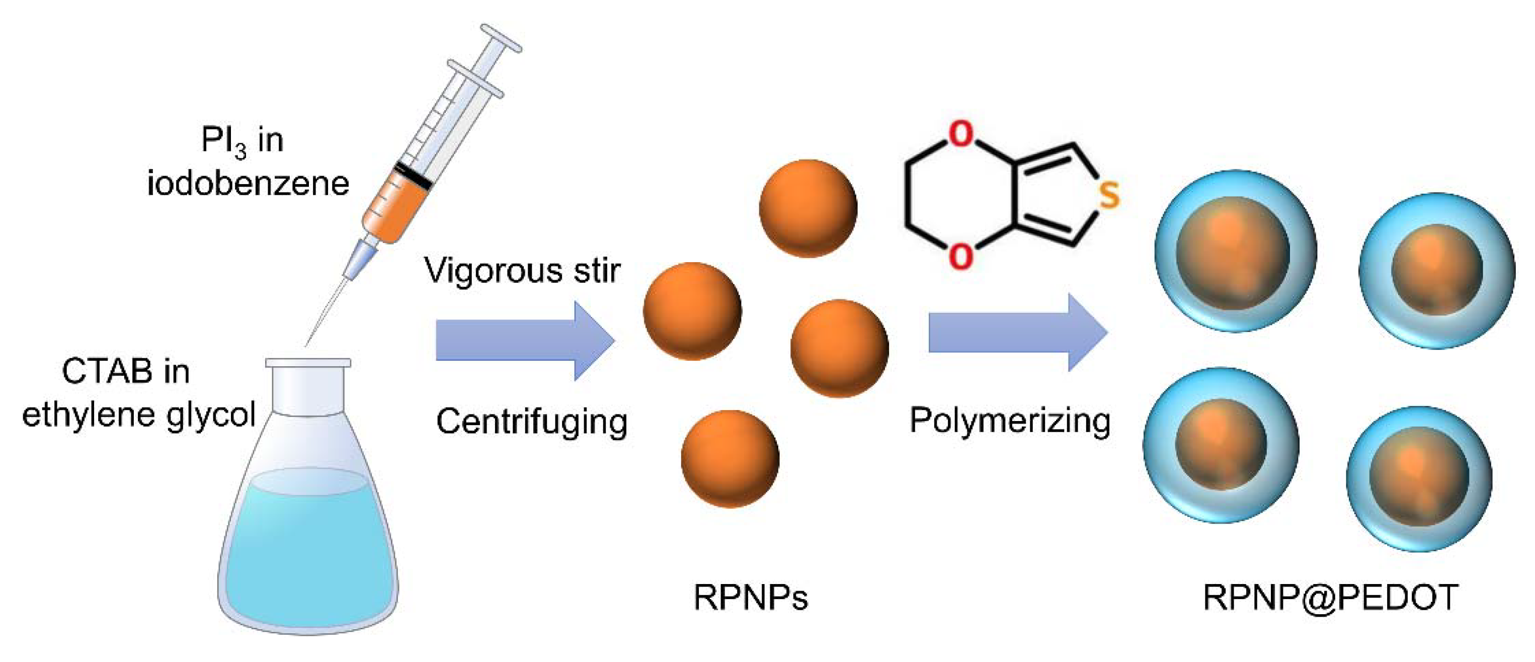
A solution-phase approach has been utilized to synthesize red phosphorus nanospheres (RPNPs) on a large scale in an ambient environment (shown in Figure 1). A total of 3.09 g of PI3 was reduced by 10 mL ethylene glycol to generate RPNPs in the presence of 0.016 mol/L CTAB by vigorous stirring for less than 10 min. CTAB was utilized as a surfactant to limit the growth of phosphorus. After centrifuging at 8000 rpm and drying in a vacuum overnight, RPNPs were obtained and stored in a glove box filled with Ar. To coat PEDOT onto RPNPs, EDOT was added to HCl solution and stirred vigorously for 0.5 h. Then, RPNPs and (NH4)2S2O8 were added to the solution and stirred for another 10 h. The resulting orange powder was washed several times with distilled water and ethanol, and dried overnight at 80 °C to get RPNP@PEDOT.
2.2. Characterization
Raman spectroscopies were obtained by a single monochromator with a microscope (Reinishaw inVia) equipped with CCD array detector, and 514 nm Argon ion laser was selected for sample excitation. The morphologies of RPNPs and RPNP@PEDOT were identified by field emission scanning electron microscopy (FESEM, SU8100, HITACHI) and high-resolution transmission electron microscopy (HRTEM, FEI Tecnai G2 F20 S-TWIN). X-ray diffraction (XRD) patterns were obtained using a Bruker equipment. The XPS spectra of RPNPs and RPNP@PEDOT were obtained by AXIS SUPRA.
2.3. Electrochemical Measurements
The K+ storage performance of RPNP@PEDOT and its control sample, RPNPs were measured with a half-cell KIB configuration. The CR2025 coin-type cells were assembled in an argon-filled glove box with both moisture and oxygen levels less than 0.1 ppm (Etelux Minilab glove box). K plates with diameters of 12 mm were used as counter electrodes. The work electrodes were prepared by mixing the active materials (80 wt%), super-P (10 wt%), and poly (vinyl difluoride) (PVDF, 10 wt%) pasting on a pure Cu foil for both KIB cell. Glass fiber (Whatman) films were used as separators for KIBs. The electrolyte used for KIBs was 1.0M KFSI in a 50:50 (v/v) mixture of ethylene carbonate (EC) and diethyl carbonate (DEC). The galvanostatic charge and discharge experiments were performed on a NEWARE multi-channel battery test system in the voltage range between 0.01 and 2.00 V vs. K/K+. The cyclic voltammetry (CV) profiles were obtained from the Autolab PGSTAT302N electrochemical workstation in the voltage range of 0.01–2.00 V vs. K/K+ at a scanning rate of 0.1 to 2.0 mV s−1.
2.4. Calculation Method
All our calculations were performed using the plane-wave Vienna Ab initio Simulation Package (VASP, version 5.4.4) [38,39,40]. A projector augmented-wave (PAW) pseudopotential method [41] was applied to describe interactions between core and valence electrons. A kinetic energy cutoff of 500 eV and Γ-centred 2 × 2 × 2, 2 × 2 × 3 and 2 × 2 × 1 k-point meshes were adopted for PEDOT, RP and PEDOT/RP heterostructure, respectively. These parameters were necessary for convergence of the total energy to within 10−5 eV per atom and force less than 0.01 eV/Å per atom. The PBEsol functional [42], a version of Perdew–Burke–Ernzerh (PBE) functional revised for solids was used for geometry optimization. The climbing image nudged elastic band (CI-NEB) method [43,44], an efficient method in determining the minimum energy diffusion path between two given positions, was applied to estimate the energy barrier for diffusion of K+.
3. Results and Discussion
3.1. Morphology and Structure of RPNP@PEDOT
The RPNPs with an average diameter of 60 nm were prepared by a facile solution-phase oxidation-reduction reaction (Figure 2a,d). After polymerization of EDOT, a conformal PEDOT layer of ~15 nm is uniformly coated onto the RPNPs, forming a hierarchical RPNP@PEDOT core-shell structure (Figure 2b,e). The wide-range TEM picture of RPNP@PEDOT is shown in Figure 2c. The corresponding HAADF image of Figure 2c is shown in Figure 2f, in which the RPNP@PEDOT particles were deformed to some extent due to relatively long-time electron irradiation during the HAADF process. Nevertheless, the contrast between the PEDOT layer and the inner RPNPs is still clear to be distinguished, further confirming the successful wrapping of PEDOT onto RPNPs.
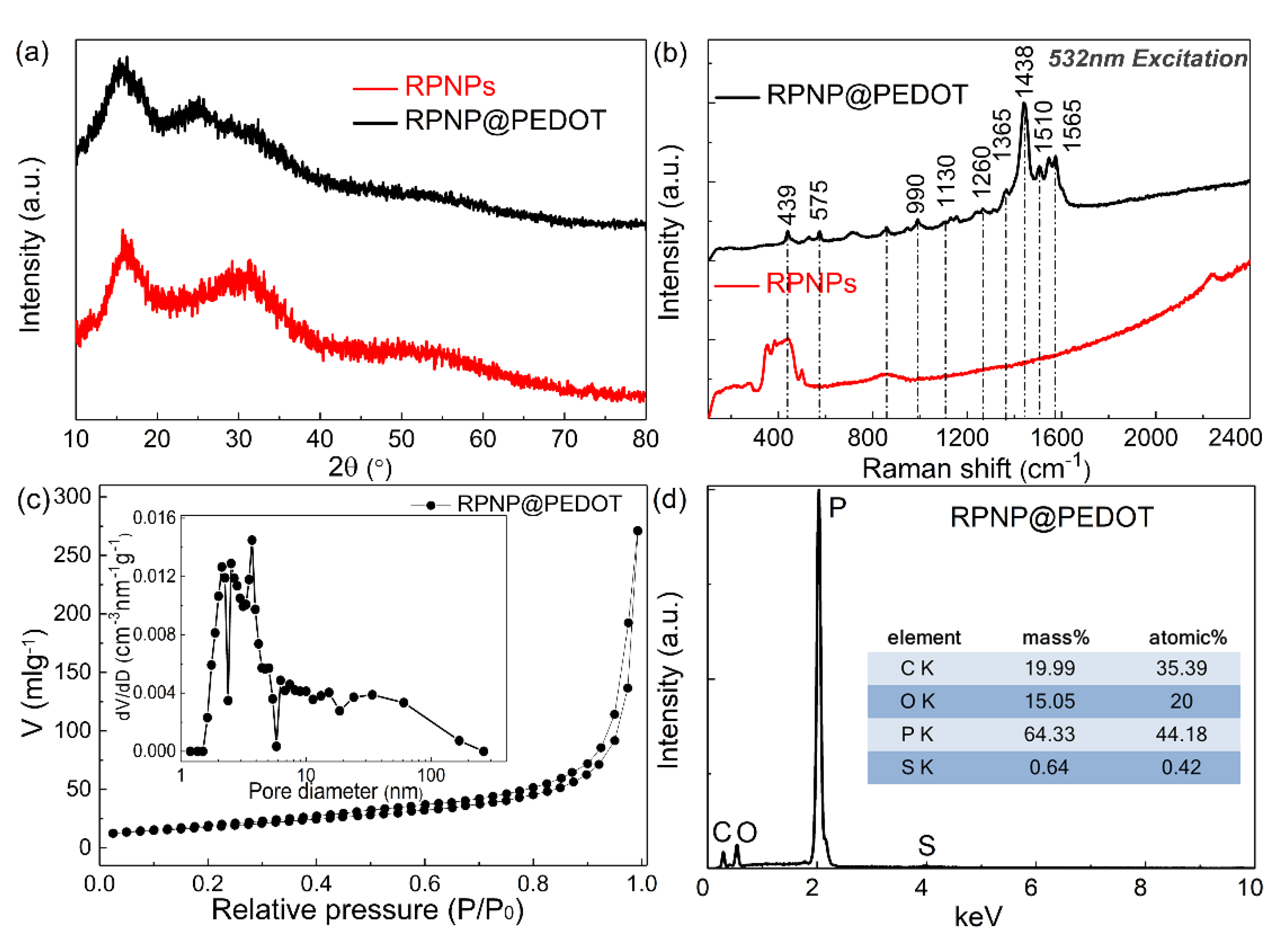
The measured XRD pattern of bare RPNPs and RPNP@PEDOT are similar to each other (Figure 3a) and dominated by three broadened diffraction peaks at 13−16°, 25−38°, and 47−65°, respectively, which is consistent with the XRD patterns of typical RP-based materials. The RP-related peak intensity in the XRD pattern of RPNP@PEDOT is weakened because of the PEDOT polymer coating layer. The measured Raman features of RPNPs are consistent with reported commercial RP, which contains a broadband within 300 to 500 cm−1. After coating PEDOT, the observed bands in the Raman spectra of RPNP@PEDOT (Figure 3b) are all attributable to PEDOT, further indicating the successful polymerization of the PEDOT layer. In particular, the strong peak located at 1438 cm−1 is associated with the symmetric stretching vibration of C=C. Compared with standard PEDOT data, the blue shift of this peak indicates good doping during the synthesis process, which enhances the conductivity of the polymer. The peak located at 1510 cm−1 is associated with the asymmetric C=C stretching vibrations.
The N2 adsorption–desorption isotherms and calculated BJH pore-size distributions of RPNP@PEDOT are shown in Figure 3c. The specific surface area of RPNP@PEDOT is 64.88 m2 g−1, which was determined from the linear portion of the Brunauer–Emmett–Teller (BET) plot. The decomposition temperature of RP (within 300–400 °C) is close to that of PEDOT. Thus, TGA measurement is unable to determine the mass content of PEDOT in RPNP@PEDOT. The SEM-EDS analysis was utilized to estimate the phosphorus content in RPNP@PEDOT. To reduce the analysis error of carbon content, RPNP@PEDOT was dispersed onto a silicon wafer other than directly attached on conductive adhesive during SEM-EDS measurements. As shown in Figure 3d, the phosphorus content is ~64.33 wt% in the RPNP@PEDOT sample.
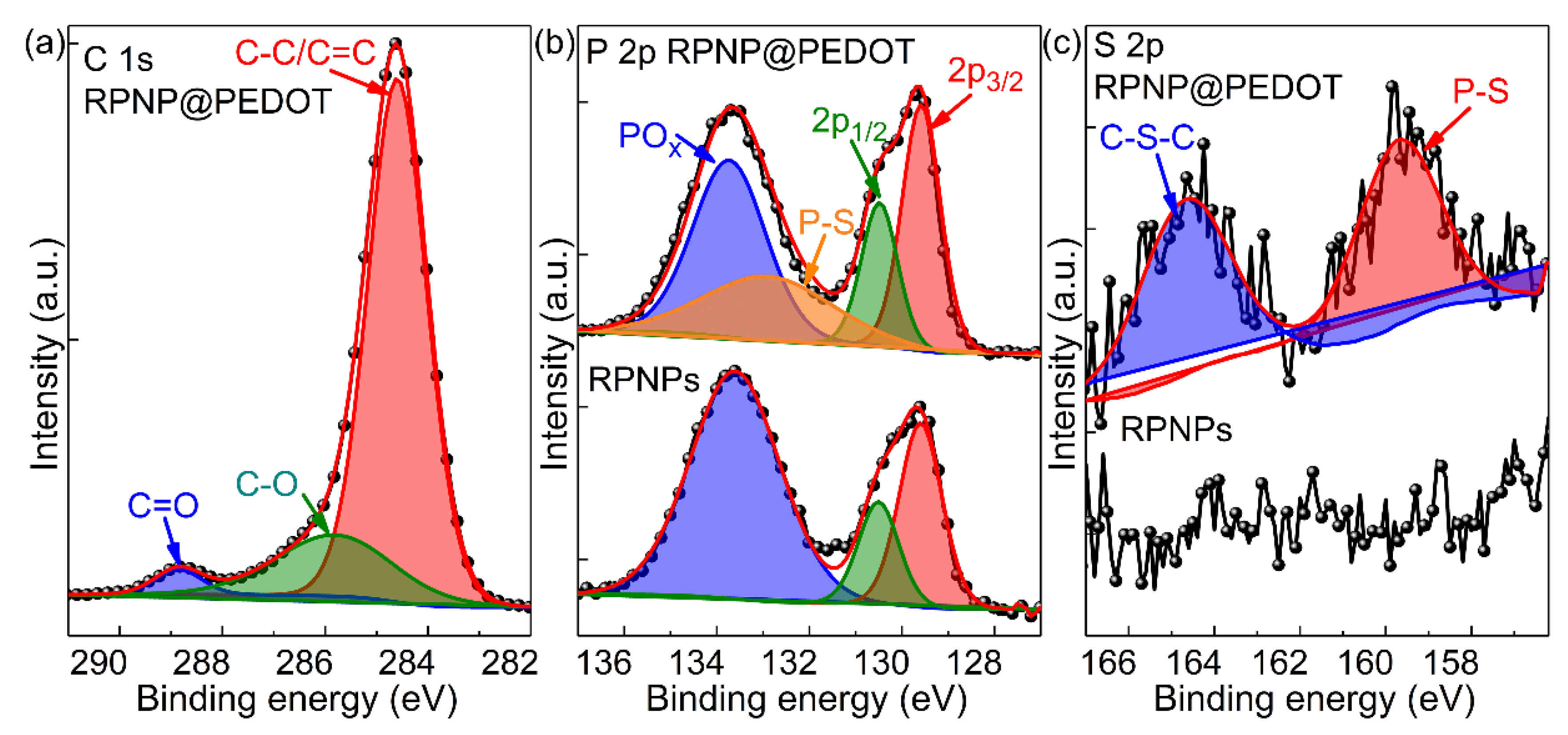
To further characterize the surface chemical composition of RPNPs and RPNP@PEDOT samples, XPS measurements were conducted. As shown in Figure 4a, the C 1s spectra of RPNP@PEDOT show three peaks at 284.6, 285.8, 288.9 eV, which are associated with C–C/C=C, C–O, C=O bonds in the PEDOT surface layer, respectively. In the XPS spectra of P 2p from RPNPs and RPNP@PEDOT (Figure 4b), the doublet located at 129.6 and 130.5 eV (split by 0.85 eV with an integrated intensity ratio of 2:1) corresponds to P 2p3/2 and P 2p1/2 orbitals, which are consistent with reported XPS data of RP. In addition, the peak located at 133.8 eV is due to the oxidation of RP and the formation of POx. RP, especially nano-sized RPNPs, is prone to oxidation in the ambient atmosphere. Compared with RPNP@PEDOT, the POx peak is much stronger in the XPS P 2p spectra of RPNPs, indicting the oxidation protection and stabilization functions of the PEDOT layer for RPNPs. In the S 2p spectrum of RPNP@PEDOT (Figure 4c), two weak peaks located at 164.6 and 159.6 eV correspond to C–S–C and P-S bonds, respectively, indicating the formation of a phosphorus–sulfur bond during the liquid-phase reaction. In contrast, no visible S 2p signal was detected in the RPNPs sample.
3.2. Potassium Ion Battery Anode Performance
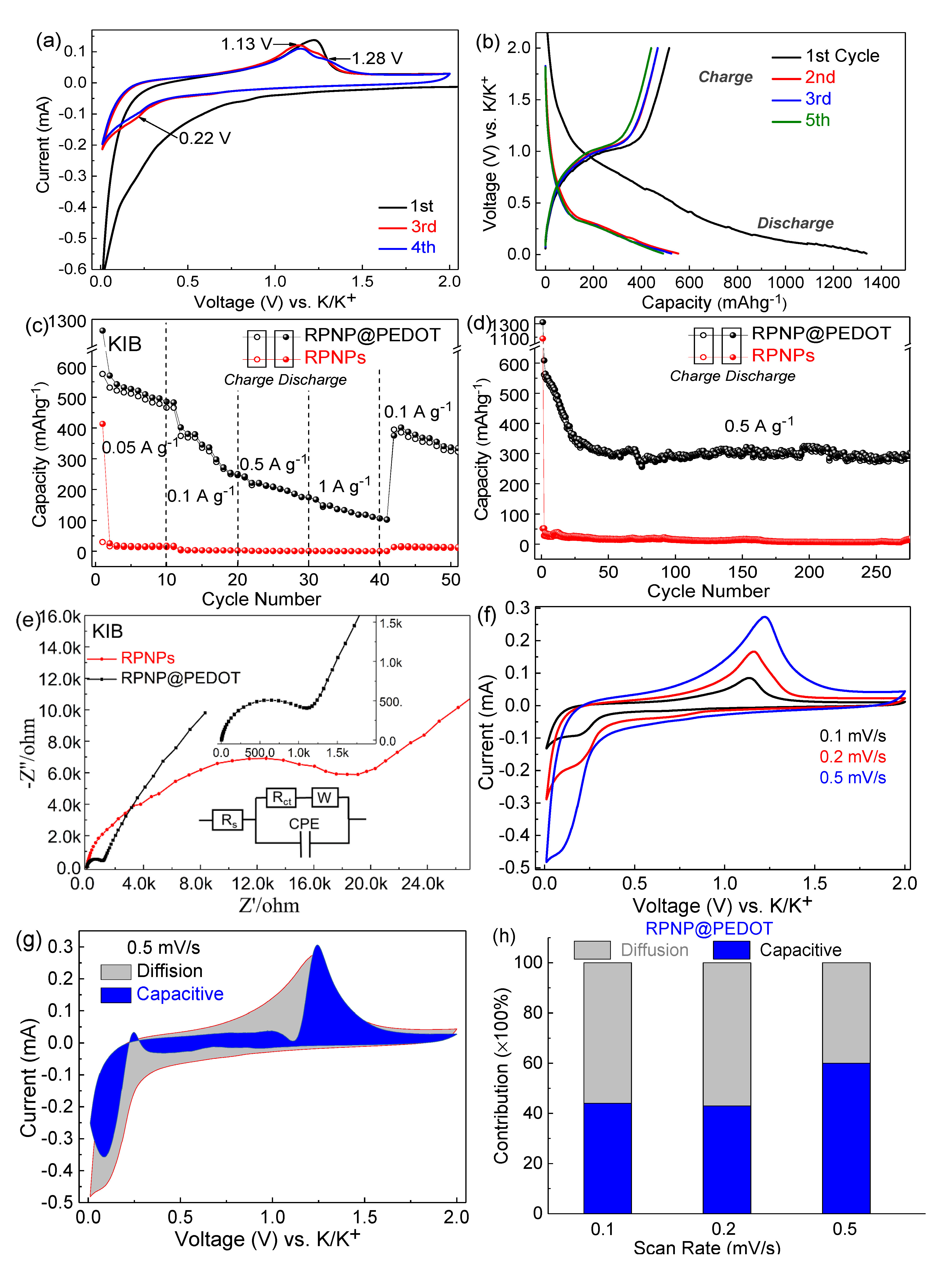
The electrochemical performances of RPNPs and RPNP@PEDOT as anodes for KIBs were investigated using a half-cell configuration. The CV profile at a scan rate of 0.2 mV s−1 and charging–discharging profiles at a current density of 0.1 A g−1 of RPNP@PEDOT are shown in Figure 5a,b to elaborate the K+ insertion/extraction mechanism. The CV peaks agree well with the correlative potential plateaus of the discharge/charge voltage profiles of RPNP@PEDOT anodes. The peak positions are consistent with most reported RP-based KIB anodes. In the CV curve of the RPNP@PEDOT KIB anode, an unrepeatable major peak at ~0.01 V (vs. K/K+) was observed in the first cathodic scan, which is associated with the SEI formation. A weak cathodic peak located at 0.22 V appeared during the subsequent cycles, which represents the K+ insertion reaction. Two oxidation peaks centered at 1.13 and 1.28 V appeared in the anodic scans due to the depotassiation processes of RP and PEDOT.
The rate performance of RPNP@PEDOT and RPNPs for KIB half-cells is illustrated in Figure 5c. The KIB performances (capacities and stability) of RPNP@PEDOT anodes are much better than those of RPNPs counterparts due to the structural protection and increased electrical conduction induced by PEDOT. The 1st discharge capacity of RPNP@PEDOT and RPNPs is 1137 and 413 mAh g−1 (at 50 mA g−1), respectively. The 2nd-cycle discharge capacities of 570, 402, 222, and 150 mAh g−1 were obtained from RPNP@PEDOT anodes at current rates of 0.05, 0.1, 0.5, and 1 A g−1, respectively, showing excellent rate performance. After changing the current back to 0.1 A g−1 after 40 cycles, the capacity recovered to 402 mA h g−1, exhibit excellent reversible performance. By contrast, the 2nd-cycle discharge capacities of 18, 3, 1, 1, and 13 mAh g−1 were obtained from RPNPs anodes at current rates of 0.05, 0.1, 0.5, 1, and 0.1 A g−1, respectively.
The KIB cycling stability at 0.5 A g−1 is shown in Figure 5d. The 1st discharge capacity of RPNP@PEDOT and RPNPs are 1322 and 1078 mAh g−1, respectively, confirming the potassium storage capability of RP. Capacity degradation was observed in the first 30 cycles in the case of RPNP@PEDOT, which is a common phenomenon for phosphorus-based anodes. After the limited degradation process, the capacity of RPNP@PEDOT stabilized at 302 mAh g−1 after 275 cycles at 0.5 A g−1, showing excellent long-term durability and fast-charging potential. As a contrast, huge capacity degradation (from 1078 to 53 mAh g−1) occurred at the 2nd-cycle in the case of RPNPs, and the capacity stabilized at only ~20 mAh g−1 at the final stage. The poor potassium storage ability of bare RPNPs is probably due to the undesirable surface condition of bare RPNPs for K+ to transport.
The electrochemical impedance spectroscopy (EIS) spectra were measured and shown by Nyquist plots (Figure 5e). In the inset equivalent circuit model, Rs, Rct, CPE, and W are the resistance between current collector and electrolyte, charge transfer resistance, constant phase element for double-layer capacitor, and Warburg impedance, respectively. The fitted Rct of RPNP@PEDOT anode (1110 Ω) is much lower than that of RPNPs anode (~20,000 Ω). Additionally, the slope of −Z’’ vs. Z’ curve at the low-frequency range for the RPNP@PEDOT anode is higher than that of the RPNPs anode, suggesting more efficient K+ diffusion and corresponding pseudocapacitance behavior of the RPNP@PEDOT.
To further investigate the pseudocapacitance behavior of the RPNP@PEDOT hybrid, the charge storage kinetics of the RPNP@PEDOT and RPNPs were evaluated by CV measurements at various scan rates (Figure 5f). The capacitive-controlled contribution ratio and diffusion-controlled contribution ratio in the RPNP@PEDOT and RPNPs anodes were quantitatively acquired using the measured CV curves and Equation (1):
where and are current density and scan rate, respectively. The k1 and k2 are constants related to capacitive contribution and diffusion contribution of the current response in the CV curves. Thus, the current at a fixed potential (V) is composed of two kinetic processes: capacitive () and diffusion-controlled () processes. The capacitive contribution of the RPNP@PEDOT at a scan rate of 0.5 mV s−1 is 62%, as illustrated in Figure 5g (blue color), and the remaining grey color region is diffusion-dominated. The capacitive contributions of the RPNP@PEDOT anode are 62%, 43%, and 44% at 0.5, 0.2, and 0.1 mV s−1, respectively (shown in Figure 5h), showing considerable pseudocapacitive K+ storage behavior.
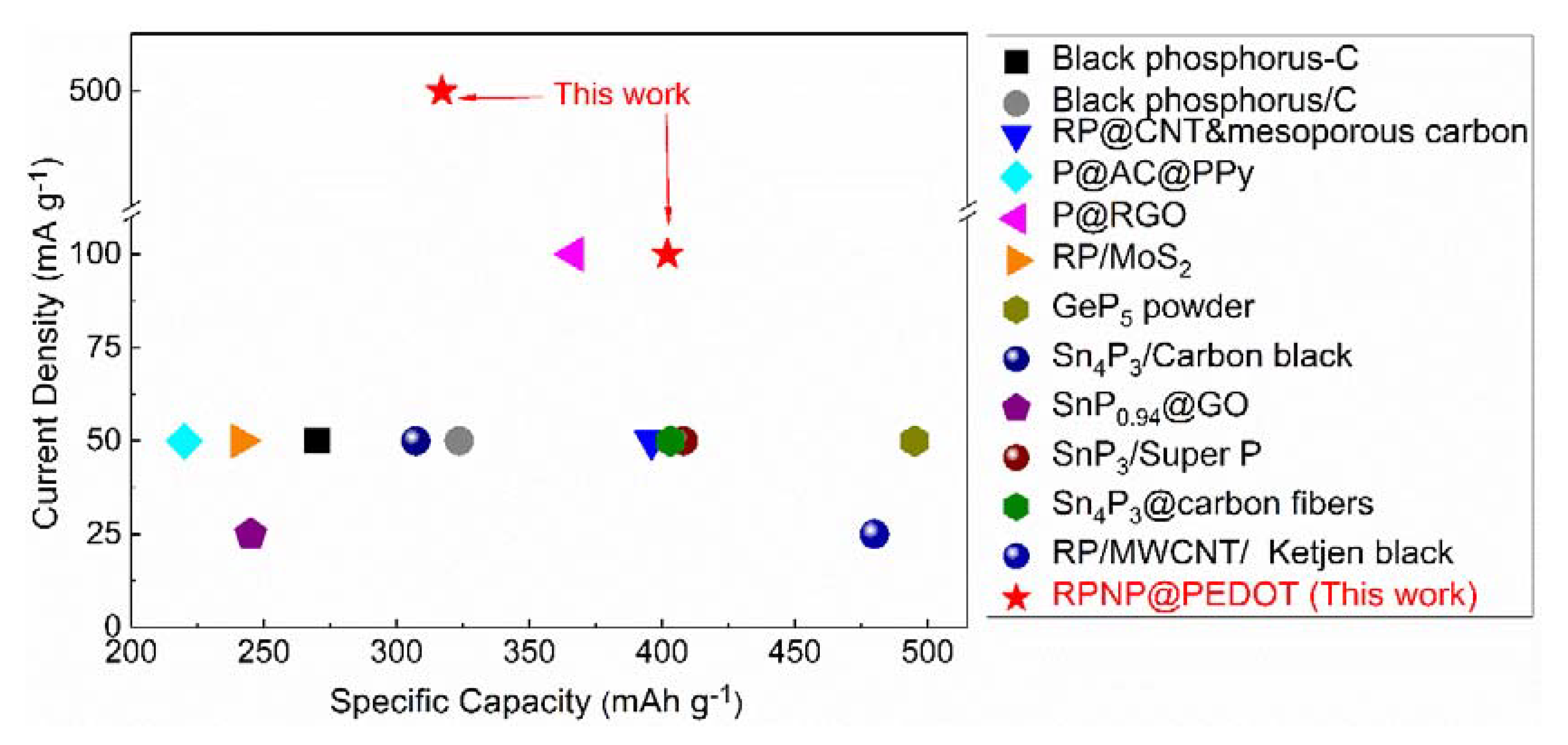
The potassium storage performance of the RPNP@PEDOT was compared with various phosphorous/carbon-based hybrids in terms of depotassiation capacity, as shown in Figure 6 and Table 1. The outstanding cycling performance of the RPNP@PEDOT can be ascribed to the strong structural stabilization effect of the PEDOT coating layer during insertion/extraction of K+ ions, whereas, the distinguished rate capacity and pseudocapacitive behavior benefit from the enhanced electron and ion conductivity induced by PEDOT.
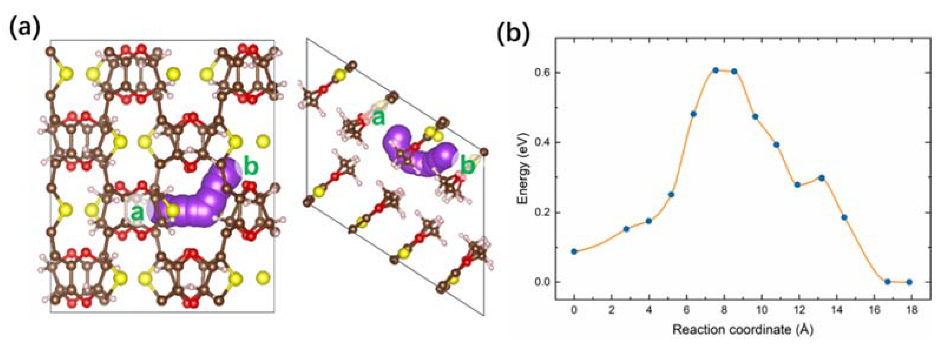
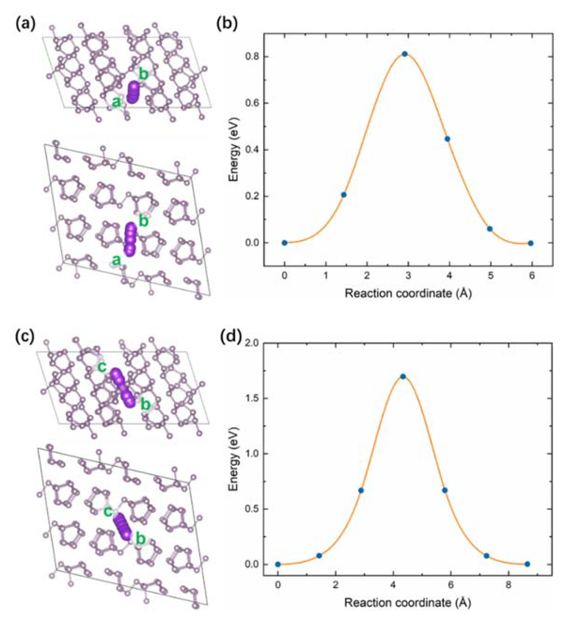
To further elucidate the improved electrochemical properties of the RPNP@PEDOT hybrid, DFT calculations were performed to investigate the diffusion behavior of K+ in the PEDOT and RP. The climbing image nudged elastic band (CI-NEB) method was applied to study the diffusion of a single K ion in the PEDOT and RP by calculating the variation in energy as K+ moves between equivalent interstitial sites. The diffusion coordinate is calculated based on the cumulative sum of the trajectory length of all atoms in the structures. Figure 7a shows the trajectory of K+ diffusion in the PEDOT molecule, while the corresponding energy profiles along pathways (a to b sites) are exhibited in Figure 7b. This pathway involves an energy barrier of 0.61 eV. In terms of K+ diffusion in the RP, two pathways were considered. One is parallel to the phosphorus layers (Figure 8a), whereas the other one is across the phosphorus layers (Figure 8c). Pathways from a to b sites have a lower energy barrier of 0.81 eV (Figure 8b). However, as K+ moves from c to d sites, it passes across a P–P bond by overcoming a higher energy barrier of 1.70 eV (Figure 8d). Compared with the diffusion barriers in the RP, the one in the PEDOT module is lower, indicating higher K+ mobility, which will help to avoid the accumulation of K ions on the surface and facilitate the storage of K ions when taking it as an anode.
4. Conclusions
The RPNP@PEDOT hybrid with a core-shell structure was synthesized by a simple liquid-phase procedure, and characterized by HRTEM, SEM, XRD, XPS and Raman scattering. The PEDOT coating can prevent the RPNPs from pulverization and fragmentation into the electrolyte during potassiation/depotassiation cycles. In addition, P–S bonding at the interface of the PEDOT and RPNPs was verified by XPS characterization, which can further stabilize the core-shell structure upon cycling. Enhanced electron and ion transportation were induced by the PEDOT due to its conjugated polymer nature. This is partially evidenced by our DFT calculation in terms of the lower diffusion barriers of K+ in the PEDOT than that in the RP. The improved electrochemical performances of the RPNP@PEDOT anode than the bare RPNPs anode are attributed to the unique inorganic-organic combination structural design. As a result, a specific capacity of 402 mAh g−1 at 0.1 A g−1 after 40 cycles, and a specific capacity of 302 mAh g−1 at 0.5 A g−1 after 275 cycles, was achieved by the RPNP@PEDOT anode, indicating its excellent potassium storage properties.
Author Contributions
Writing—original draft preparation, D.Z. and Q.Z.; Methodology, L.F.; the preparation of the materials, D.Z.; writing—review and editing, J.Z.; validation, C.N.; DFT calculation, Z.W. All authors have read and agreed to the published version of the manuscript.
Funding
This research was funded by the National Natural Science Foundation of China (No. 52002233), and the Natural Science Fund of Shaanxi University of Science and Technology (No. 2018BJ-59).
Institutional Review Board Statement
Not applicable.
Informed Consent Statement
Not applicable.
Conflicts of Interest
The authors declare no conflict of interest.
References
- Lu, L.; Han, X.; Li, J.; Hua, J.; Ouyang, M. A review on the key issues for lithium-ion battery management in electric vehicles. J. Power Sources 2013, 226, 272–288. [Google Scholar] [CrossRef]
- Heyd, J.; Scuseria, G.E.; Ernzerhof, M. Hybrid functionals based on a screened Coulomb potential. J. Chem. Phys. 2003, 118, 8207–8215. [Google Scholar] [CrossRef] [Green Version]
- Liu, Y.; Zhang, A.; Shen, C.; Liu, Q.; Cao, X.; Ma, Y.; Chen, L.; Lau, C.; Chen, T.-C.; Wei, F.; et al. Red Phosphorus Nanodots on Reduced Graphene Oxide as a Flexible and Ultra-Fast Anode for Sodium-Ion Batteries. ACS Nano 2017, 11, 5530–5537. [Google Scholar] [CrossRef] [PubMed]
- Ma, G.; Huang, K.; Ma, J.-S.; Ju, Z.; Xing, Z.; Zhuang, Q.-C. Phosphorus and oxygen dual-doped graphene as superior anode material for room-temperature potassium-ion batteries. J. Mater. Chem. A 2017, 5, 7854–7861. [Google Scholar] [CrossRef]
- Sultana, I.; Rahman, M.; Ramireddy, T.; Chen, Y.; Glushenkov, A.M. High capacity potassium-ion battery anodes based on black phosphorus. J. Mater. Chem. A 2017, 5, 23506–23512. [Google Scholar] [CrossRef]
- Chang, W.; Wu, J.; Chen, K.; Tuan, H. Potassium-ion batteries: Red phosphorus potassium-ion battery anodes. Adv. Sci. 2019, 6, 1970052. [Google Scholar] [CrossRef]
- Wu, Y.; Huang, H.; Feng, Y.; Wu, Z.; Yu, Y. The Promise and Challenge of Phosphorus-Based Composites as Anode Materials for Potassium-Ion Batteries. Adv. Mater. 2019, 31, e1901414. [Google Scholar] [CrossRef] [PubMed]
- Fang, K.; Liu, D.; Xiang, X.; Zhu, X.; Tang, H.; Qu, D.; Xie, Z.; Li, J.; Qu, D. Air-stable red phosphorus anode for potassium/sodium-ion batteries enabled through dual-protection design. Nano Energy 2020, 69, 104451. [Google Scholar] [CrossRef]
- Su, D.S.; Centi, G. A perspective on carbon materials for future energy application. J. Energy Chem. 2013, 22, 151–173. [Google Scholar] [CrossRef]
- Zhu, Z.; Chen, J. Review—Advanced Carbon-Supported Organic Electrode Materials for Lithium (Sodium)-Ion Batteries. J. Electrochem. Soc. 2015, 162, A2393–A2405. [Google Scholar] [CrossRef]
- Hou, H.; Qiu, X.; Wei, W.; Zhang, Y.; Ji, X. Carbon Anode Materials for Advanced Sodium-Ion Batteries. Adv. Energy Mater. 2017, 7, 1602898. [Google Scholar] [CrossRef]
- Yu, H.; Guo, S.; Zhu, Y.; Ishida, M.; Zhou, H. Novel titanium-based O3-type NaTi0.5Ni0.5O2 as a cathode material for sodium ion batteries. Chem. Commun. 2014, 50, 457–459. [Google Scholar] [CrossRef] [PubMed]
- Guo, S.; Yi, J.; Sun, Y.; Zhou, H. Recent advances in titanium-based electrode materials for stationary sodium-ion batteries. Energy Environ. Sci. 2016, 9, 2978–3006. [Google Scholar] [CrossRef]
- Mortazavi, M.; Ye, Q.; Birbilis, N.; Medhekar, N. High capacity group-15 alloy anodes for Na-ion batteries: Electrochemical and mechanical insights. J. Power Sources 2015, 285, 29–36. [Google Scholar] [CrossRef]
- Lao, M.; Zhang, Y.; Luo, W.; Yan, Q.; Sun, W.; Dou, S.X. Alloy-based anode materials toward advanced sodium-ion batteries. Adv. Mater. 2017, 29, 1700622. [Google Scholar] [CrossRef]
- Carenco, S.; Portehault, D.; Boissière, C.; Mézailles, N.; Sanchez, C. Nanoscaled Metal Borides and Phosphides: Recent Developments and Perspectives. Chem. Rev. 2013, 113, 7981–8065. [Google Scholar] [CrossRef]
- Wu, H.; Xia, B.Y.; Yu, L.; Yu, X.-Y.; Lou, X.W. (David) Porous molybdenum carbide nano-octahedrons synthesized via confined carburization in metal-organic frameworks for efficient hydrogen production. Nat. Commun. 2015, 6, 6512. [Google Scholar] [CrossRef]
- Zhang, Y.; Zhou, Q.; Zhu, J.; Yan, Q.; Dou, S.X.; Sun, W. Nanostructured Metal Chalcogenides for Energy Storage and Electrocatalysis. Adv. Funct. Mater. 2017, 27, 27. [Google Scholar] [CrossRef]
- Yang, F.; Gao, H.; Chen, J.; Guo, Z. Phosphorus-Based Materials as the Anode for Sodium-Ion Batteries. Small Methods 2017, 1, 1700216. [Google Scholar] [CrossRef]
- Wu, Y.; Hu, S.; Xu, R.; Wang, J.; Peng, Z.; Zhang, Q.; Yu, Y. Boosting Potassium-Ion Battery Performance by Encapsulating Red Phosphorus in Free-Standing Nitrogen-Doped Porous Hollow Carbon Nanofibers. Nano Lett. 2019, 19, 1351–1358. [Google Scholar] [CrossRef]
- Liu, W.; Ju, S.; Yu, X. Phosphorus-Amine-Based Synthesis of Nanoscale Red Phosphorus for Application to Sodium-Ion Batteries. ACS Nano 2019, 14, 974–984. [Google Scholar] [CrossRef]
- Liu, C.; Han, X.; Cao, Y.; Zhang, S.; Zhang, Y.; Sun, J. Topological construction of phosphorus and carbon composite and its application in energy storage. Energy Storage Mater. 2019, 20, 343–372. [Google Scholar] [CrossRef]
- Li, S.; Qiu, J.; Lai, C.; Ling, M.; Zhao, H.; Zhang, S. Surface capacitive contributions: Towards high rate anode materials for sodium ion batteries. Nano Energy 2015, 12, 224–230. [Google Scholar] [CrossRef]
- Simon, P.; Gogotsi, Y.; Dunn, B. Where Do Batteries End and Supercapacitors Begin? Science 2014, 343, 1210–1211. [Google Scholar] [CrossRef] [Green Version]
- Liu, S.; Xu, H.; Bian, X.; Feng, J.; Liu, J.; Yang, Y.; Yuan, C.; An, Y.; Fan, R.; Ci, L. Hollow nanoporous red phosphorus as an advanced anode for sodium-ion batteries. J. Mater. Chem. A 2018, 6, 12992–12998. [Google Scholar] [CrossRef]
- Liu, S.; Xu, H.; Bian, X.; Feng, J.; Liu, J.; Yang, Y.; Yuan, C.; An, Y.; Fan, R.; Ci, L. Nanoporous Red Phosphorus on Reduced Graphene Oxide as Superior Anode for Sodium-Ion Batteries. ACS Nano 2018, 12, 7380–7387. [Google Scholar] [CrossRef]
- Gao, H.; Zhou, T.; Zheng, Y.; Liu, Y.; Chen, J.; Liu, H.K.; Guo, Z. Integrated Carbon/Red Phosphorus/Graphene Aerogel 3D Architecture via Advanced Vapor-Redistribution for High-Energy Sodium-Ion Batteries. Adv. Energy Mater. 2016, 6, 1601037. [Google Scholar] [CrossRef]
- Zhang, Y.; Rui, X.; Tang, Y.; Liu, Y.; Wei, J.; Chen, S.; Leow, W.R.; Li, W.; Liu, Y.; Deng, J.; et al. Wet-Chemical Processing of Phosphorus Composite Nanosheets for High-Rate and High-Capacity Lithium-Ion Batteries. Adv. Energy Mater. 2016, 6, 1502409. [Google Scholar] [CrossRef]
- Conte, D.E.; Pinna, N. A review on the application of iron(III) fluorides as positive electrodes for secondary cells. Mater. Renew. Sustain. Energy 2014, 3, 1–22. [Google Scholar] [CrossRef] [Green Version]
- Kim, J.; Yoo, J.-K.; Jung, Y.S.; Kang, K. Li3V2(PO4)3/Conducting Polymer as a High Power 4 V-Class Lithium Battery Electrode. Adv. Energy Mater. 2013, 3, 1004–1007. [Google Scholar] [CrossRef]
- Chen, H.-W.; Li, C. PEDOT: Fundamentals and Its Nanocomposites for Energy Storage. Chin. J. Polym. Sci. 2019, 38, 435–448. [Google Scholar] [CrossRef]
- Kim, J.; Kim, J.H.; Ariga, K. Redox-active polymers for energy storage nanoarchitectonics. Joule 2017, 1, 739–768. [Google Scholar] [CrossRef] [Green Version]
- Kim, J.; Lee, J.; You, J.; Park, M.-S.; Hossain, M.S.A.; Yamauchi, Y.; Kim, J.H. Conductive polymers for next-generation energy storage systems: Recent progress and new functions. Mater. Horiz. 2016, 3, 517–535. [Google Scholar] [CrossRef]
- Chang, W.-C.; Tseng, K.-W.; Tuan, H.-Y. Solution Synthesis of Iodine-Doped Red Phosphorus Nanoparticles for Lithium-Ion Battery Anodes. Nano Lett. 2017, 17, 1240–1247. [Google Scholar] [CrossRef] [PubMed]
- Zeng, Y.; Yi, H.; Zhao, Y.; Yan, Z.; Lu, X. Advanced Ti-doped Fe2O3@PEDOT core/shell anode for high-energy asymmetric supercapacitors. Adv. Energy Mater. 2015, 5, 1402176. [Google Scholar] [CrossRef]
- Fan, X.; Luo, C.; Lamb, J.; Zhu, Y.; Xu, K.; Wang, C. PEDOT Encapsulated FeOF Nanorod Cathodes for High Energy Lithium-Ion Batteries. Nano Lett. 2015, 15, 7650–7656. [Google Scholar] [CrossRef]
- Zhang, Q.; He, Y.; Mei, P.; Cui, X.; Yang, Y.; Lin, Z. Multi-functional PEDOT-engineered sodium titanate nanowires for sodium–ion batteries with synchronous improvements in rate capability and structural stability. J. Mater. Chem. A 2019, 7, 19241–19247. [Google Scholar] [CrossRef]
- Kresse, G.; Hafner, J. Ab initio molecular dynamics for liquid metals. Phys. Rev. B 1993, 47, 558. [Google Scholar] [CrossRef]
- Kresse, G.; Furthmüller, J.; Hafner, J. Theory of the crystal structures of selenium and tellurium: The effect of generalized-gradient corrections to the local-density approximation. Phys. Rev. B 1994, 50, 13181–13185. [Google Scholar] [CrossRef]
- Kresse, G.; Furthmüller, J. Efficiency of ab-initio total energy calculations for metals and semiconductors using a plane-wave basis set. Comput. Mater. Sci. 1996, 6, 15–50. [Google Scholar] [CrossRef]
- Blöchl, P.E. Projector augmented-wave method. Phys. Rev. B 1994, 50, 17953. [Google Scholar] [CrossRef] [Green Version]
- Perdew, J.P.; Ruzsinszky, A.; Csonka, G.I.; Vydrov, O.A.; Scuseria, G.E.; Constantin, L.; Zhou, X.; Burke, K. Restoring the Density-Gradient Expansion for Exchange in Solids and Surfaces. Phys. Rev. Lett. 2008, 100, 136406. [Google Scholar] [CrossRef] [PubMed] [Green Version]
- Henkelman, G.; Uberuaga, B.; Jónsson, H. A climbing image nudged elastic band method for finding saddle points and minimum energy paths. J. Chem. Phys. 2000, 113, 9901–9904. [Google Scholar] [CrossRef] [Green Version]
- Henkelman, G.; Jónsson, H. Improved tangent estimate in the nudged elastic band method for finding minimum energy paths and saddle points. J. Chem. Phys. 2000, 113, 9978–9985. [Google Scholar] [CrossRef] [Green Version]
- Wu, X.; Zhao, W.; Wang, H.; Qi, X.; Xing, Z.; Zhuang, Q.; Ju, Z. Enhanced capacity of chemically bonded phosphorus/carbon composite as an anode material for potassium-ion batteries. J. Power Sources 2018, 378, 460–467. [Google Scholar] [CrossRef]
- Liu, D.; Huang, X.; Qu, D.; Zheng, D.; Wang, G.; Harris, J.; Si, J.; Ding, T.; Chen, J.; Qu, D. Confined phosphorus in carbon nanotube-backboned mesoporous carbon as superior anode material for sodium/potassium-ion batteries. Nano Energy 2018, 52, 1–10. [Google Scholar] [CrossRef]
- Wang, H.; Wang, L.; Wang, L.; Xing, Z.; Wu, X.; Zhao, W.; Qi, X.; Ju, Z.; Zhuang, Q. Phosphorus Particles Embedded in Reduced Graphene Oxide Matrix to Enhance Capacity and Rate Capability for Capacitive Potassium-Ion Storage. Chem. A Eur. J. 2018, 24, 13897–13902. [Google Scholar] [CrossRef] [PubMed]
- Gao, Y.; Ru, Q.; Liu, Y.; Cheng, S.; Wei, L.; Ling, F.; Chen, F.; Hou, X. Mosaic Red Phosphorus/MoS2 Hybrid as an Anode to Boost Potassium-Ion Storage. ChemElectroChem 2019, 6, 4689–4695. [Google Scholar] [CrossRef]
- Zhang, W.; Wu, Z.; Zhang, J.; Liu, G.; Yang, N.-H.; Liu, R.-S.; Pang, W.K.; Li, W.; Guo, Z. Unraveling the effect of salt chemistry on long-durability high-phosphorus-concentration anode for potassium ion batteries. Nano Energy 2018, 53, 967–974. [Google Scholar] [CrossRef] [Green Version]
- Zhang, W.; Mao, J.; Li, S.; Chen, Z.; Guo, Z. Phosphorus-Based Alloy Materials for Advanced Potassium-Ion Battery Anode. J. Am. Chem. Soc. 2017, 139, 3316–3319. [Google Scholar] [CrossRef] [Green Version]
- Zhao, X.; Wang, W.; Hou, Z.; Wei, G.; Yu, Y.; Zhang, J.; Quan, Z. SnP0.94 nanoplates/graphene oxide composite for novel potassium-ion battery anode. Chem. Eng. J. 2019, 370, 677–683. [Google Scholar] [CrossRef]
- Verma, R.; Didwal, P.N.; Ki, H.-S.; Cao, G.-Z.; Park, C.-J. SnP3/Carbon Nanocomposite as an Anode Material for Potassium-Ion Batteries. ACS Appl. Mater. Interfaces 2019, 11, 26976–26984. [Google Scholar] [CrossRef] [PubMed]
- Zhang, W.; Pang, W.K.; Sencadas, V.; Guo, Z. Understanding High-Energy-Density Sn4P3 Anodes for Potassium-Ion Batteries. Joule 2018, 2, 1534–1547. [Google Scholar] [CrossRef] [Green Version]
Figure 1.
Schematic illustration of synthesis procedure of RPNPs and RPNP@PEDOT.

Figure 2.
TEM images of (a) RPNPs and (b) RPNP@PEDOT; SEM images of (d) RPNPs and (e) RPNP@PEDOT; (c) wide-range TEM picture of RPNP@PEDOT and (f) the corresponding HAADF image of RPNP@PEDOT.
Figure 2.
TEM images of (a) RPNPs and (b) RPNP@PEDOT; SEM images of (d) RPNPs and (e) RPNP@PEDOT; (c) wide-range TEM picture of RPNP@PEDOT and (f) the corresponding HAADF image of RPNP@PEDOT.

Figure 3.
(a) XRD patterns and (b) Raman spectra of RPNPs (red) and RPNP@PEDOT (black); (c) Nitrogen adsorption and desorption isotherms and (d) SEM-EDS elemental analysis for RPNP@PEDOT.
Figure 3.
(a) XRD patterns and (b) Raman spectra of RPNPs (red) and RPNP@PEDOT (black); (c) Nitrogen adsorption and desorption isotherms and (d) SEM-EDS elemental analysis for RPNP@PEDOT.

Figure 4.
XPS spectrum of RPNPs and RPNP@PEDOT: (a) C 1s, (b) P 2p, and (c) S 2p.

Figure 5.
KIB performances of RPNPs and RPNP@PEDOT anodes. (a) CV profile at a scan rate of 0.2 mV s−1; (b) Charge-discharge voltage profiles at 0.1 A g−1; (c) Rate capacities; (d) Cycling performance of RPNP@PEDOT anodes at 0.5 A g−1; (e) Nyquist plots from 0.01 Hz to 100 kHz; (f) CV curves of RPNP@PEDOT anode at different scan rates; (g) Capacitive and diffusion current contributions to the charge storage of RPNP@PEDOT at a scan rate of 2.0 mV s−1. (h) Charge contributions from capacitance and diffusion at various scan rates for RPNP@PEDOT anode.

Figure 6.
KIB performance comparisons of various phosphorus-based anodes. The specific capacity figures are reliable data after cycling at least 40 cycles.
Figure 6.
KIB performance comparisons of various phosphorus-based anodes. The specific capacity figures are reliable data after cycling at least 40 cycles.

Figure 7.
(a) Schematic diagram of diffusion pathway in the PEDOT, and (b) the energy profile of the K diffusion from sites a to b.
Figure 7.
(a) Schematic diagram of diffusion pathway in the PEDOT, and (b) the energy profile of the K diffusion from sites a to b.

Figure 8.
Schematic diagram of diffusion pathway in the RP (a) from site a to b, and (c) from site c to b. The energy profile of the K+ diffusion of the two pathways is shown in (b,d), respectively.
Figure 8.
Schematic diagram of diffusion pathway in the RP (a) from site a to b, and (c) from site c to b. The energy profile of the K+ diffusion of the two pathways is shown in (b,d), respectively.


Table 1.
Comparison of the potassium storage performance of various phosphorous/carbon-based hybrids.
Table 1.
Comparison of the potassium storage performance of various phosphorous/carbon-based hybrids.
| Material | Synthetic Method | Cycling Stability (after n Cycles) | References |
|---|---|---|---|
| Black phosphorus-C | ball-milling | 270 mAh g−1 at 50 mA g−1 after 50 cycles | [5] |
| Black phosphorus/C | ball-milling | 323.5 mA h g−1 at 50 mA g−1 after 50 cycles | [45] |
| RP/MWCNT/Ketjen black | Wet-ball milling | 480 mA h g−1 at 25 mA g−1 after 50 cycles (recalculated based on the whole electrode mass) | [20] |
| RP@CNT mesoporous carbon | vaporization/condensation | 396 mAh g−1 at 50 mA g−1 after 75 cycles | [46] |
| P@AC@PPy | vaporization/condensation | 220 mAh g−1 at 50 mA g−1 after 200 cycles | [8] |
| P@RGO | vaporization/condensation | 366.6 mAh g−1 at 100 mA g−1 after 50 cycles | [47] |
| RP/MoS2 | ball-milling | 241.4 mAhg−1 at 50 mAg−1 after 120 cycles | [48] |
| GeP5 powder | ball-milling | 495.1 mAh g−1 at 50 mA g−1 after 50 cycles | [49] |
| Sn4P3/Carbon black | ball-milling | 307.2 mAh g−1 at 50 mA g−1 after 50 cycles | [50] |
| SnP0.94@GO | hot-injection | 245 mA h g−1 at 25 mA g−1 after 50 cycles. | [51] |
| SnP3/Super P | ball-milling | 408 mAh g−1 at 50 mA g−1 after 50 cycles | [52] |
| Sn4P3@carbon fibers | Ball-milling; electrospinning | 403.1 mAh g−1 at 50 mA g−1 after 200 cycles | [53] |
| RPNP@PEDOT | solution phase | 402 mAh g−1 at 100 mA g−1 after 50 cycles of rate testing at various current rates; 302 mAh g−1 at 500 mA g−1 after 275 cycles of rate testing at various current rates | This work |
Publisher’s Note: MDPI stays neutral with regard to jurisdictional claims in published maps and institutional affiliations. |
© 2021 by the authors. Licensee MDPI, Basel, Switzerland. This article is an open access article distributed under the terms and conditions of the Creative Commons Attribution (CC BY) license (https://creativecommons.org/licenses/by/4.0/).
Share and Cite
MDPI and ACS Style
Zhao, D.; Zhao, Q.; Wang, Z.; Feng, L.; Zhang, J.; Niu, C. PEDOT-Coated Red Phosphorus Nanosphere Anodes for Pseudocapacitive Potassium-Ion Storage. Nanomaterials 2021, 11, 1732. https://doi.org/10.3390/nano11071732
AMA Style
Zhao D, Zhao Q, Wang Z, Feng L, Zhang J, Niu C. PEDOT-Coated Red Phosphorus Nanosphere Anodes for Pseudocapacitive Potassium-Ion Storage. Nanomaterials. 2021; 11(7):1732. https://doi.org/10.3390/nano11071732
Chicago/Turabian StyleZhao, Dan, Qian Zhao, Zhenyu Wang, Lan Feng, Jinying Zhang, and Chunming Niu. 2021. "PEDOT-Coated Red Phosphorus Nanosphere Anodes for Pseudocapacitive Potassium-Ion Storage" Nanomaterials 11, no. 7: 1732. https://doi.org/10.3390/nano11071732
Note that from the first issue of 2016, this journal uses article numbers instead of page numbers. See further details here.