Article

Fabrication and Characterisation of Stimuli Responsive Piezoelectric PVDF and Hydroxyapatite-Filled PVDF Fibrous Membranes

1
School of Materials, MSS Tower, The University of Manchester, Manchester M13 9PL, UK
2
Bio-Active Materials Group, School of Materials, MSS Tower, The University of Manchester, Manchester M13 9PL, UK
3
Department of Fibre and Polymer Technology, School of Chemical Science and Engineering, KTH Royal Institute of Technology, Teknikringen 56, SE-10044 Stockholm, Sweden
*
Authors to whom correspondence should be addressed.
Molecules 2019, 24(10), 1903; https://doi.org/10.3390/molecules24101903
Submission received: 2 April 2019 / Revised: 13 May 2019 / Accepted: 14 May 2019 / Published: 17 May 2019
(This article belongs to the Special Issue Stimuli-Responsive Polymeric Materials)

Abstract

:
Poly(vinylidene fluoride) has attracted interest from the biomaterials community owing to its stimuli responsive piezoelectric property and promising results for application in the field of tissue engineering. Here, solution blow spinning and electrospinning were employed to fabricate PVDF fibres and the variation in resultant fibre properties assessed. The proportion of piezoelectric β-phase in the solution blow spun fibres was higher than electrospun fibres. Fibre production rate was circa three times higher for solution blow spinning compared to electrospinning for the conditions explored. However, the solution blow spinning method resulted in higher fibre variability between fabricated batches. Fibrous membranes are capable of generating different cellular response depending on fibre diameter. For this reason, electrospun fibres with micron and sub-micron diameters were fabricated, along with successful inclusion of hydroxyapatite particles to fabricate stimuli responsive bioactive fibres.

1. Introduction

Stimuli responsive polymers are a class of materials capable of responding to one or more stimuli such as mechanical, photo, electrical (physical stimuli), pH, electrochemical gradients (chemical stimuli), enzymes and receptors (biological stimuli) [1,2]. The stimuli responsive nature of these materials has been exploited for applications such as drug delivery and tissue engineering [3]. Poly(vinylidene fluoride) (PVDF) and its copolymers can exhibit piezoelectricity, pyroelectricity and ferroelectricity, and are classified as stimuli responsive polymers. These polymers have been utilised alone or as matrices in composites and layered structures to fabricate stimuli responsive systems [4,5,6]. Tissue engineering scaffolds fabricated using these materials are capable of generating electrical stimuli in response to mechanical deformation, which consequently affect cellular differentiation [7,8,9,10]. The incorporation of particles of hydroxyapatite (HA), itself a piezoelectric material, into polymer and ceramic matrices has been shown to impart bioactive properties, improve bone forming ability and apatite formation [11,12,13,14].
Electrospinning (ES) has been utilised to fabricate nanofibre membranes for various applications such as tissue engineering [15,16], sensors [17,18] and filtration [19] over the past two decades. To date, ES has been the predominant technique used to produce sub-micron fibres from PVDF and its copolymers [8,20,21,22,23]. However, the requirement for high voltage setups, conductive collectors and the relatively low fibre production rates typical of the technique can pose issues for scale-up [24,25]. Solution blow spinning (SBS) has emerged an alternative technique for sub-micron/nanofibre fabrication [24,26], it does not require electric fields and offers high throughput making it attractive for industrial scale-up [27,28]. There have been instances where SBS has been used to fabricate fibrous PVDF [29] and poly(vinylidene fluoride)-co-tetrafluoroethylene (PVDF-co-TrFE) [30] membranes, albeit very few in comparison to electrospinning. Differences in PVDF-based polymer composition, molecular weight, spinning technique and experimental parameters have been shown to significantly impact the resultant fibres [20,31,32,33,34].
Difference in fibre diameter influences the roughness and inter-fibre pore sizes of membranes and scaffolds used in tissue engineering applications and can have a direct influence on cellular adhesion, proliferation and differentiation [35,36,37]. Controlling fibre size is a strategy that can be used to tune pore size and mimic aspects of the extracellular matrix (ECM) to alter cell infiltration [38]. This approach has been shown to enable the migration of human osteosarcoma cells (SaOs-2 cell line) from one side of a fibre membrane to the other, and support their proliferation [38]. The differentiation and spreading of osteoblastic cell line, MC3T3-E1 cells has also been reported to be affected by fibre diameter [37].
In this work, the effect of PVDF molecular weight and spinning technique on fibre properties were investigated, specifically, fibre morphology, diameter distribution, mat quality, production rate, thermal, wettability, mechanical and piezoelectric properties, as well as the effect of HA particulate inclusion within the fibres. The properties of the PVDF fibre mats were also compared to films of non-polarised (non-piezoelectric) and polarised (piezoelectric) PVDF. Batch-to-batch variation analysis was also conducted to assess the reproducibility between the two spinning techniques.

2. Results and Discussions

Representative scanning electron microscopy (SEM) images of the fibre mats are shown in Figure 1a. Fibre alignment, in the direction of the rotating collector was evident (Figure 1a (i) and (ii)). Alignment of ES fibres was apparently higher than those produced by SBS in this study (Figure 1a). This could be due to increased turbulence around the collector due to high rotation speed [39] and compressed air deflecting from the surface of the cylindrical collector. Mean fibre diameters of 400 ± 130 nm and 300 ± 90 nm were obtained for SBS and ES, respectively. All fibres exhibited relatively smooth morphologies. The fibre diameter and morphology observed for PVDF fibres was similar to previously reported for ES PVDF [40,41]. Previous studies concerning fibre spinning of PVDF using ES and SBS yielded similar results supporting successful fabrication of nanofibrous PVDF membranes [20,22,23,29]. The presence of beads in PVDF275SBSA25 was in accordance with previous results obtained with SBS of PVDF-co-TrFE [30] and may stem from a local higher concentration of polymer and charge accumulation [42].
Tensile testing revealed PVDF275SBSA25 fibre mats to have higher tensile strength (16.2 MPa) and Young’s modulus (1.2 MPa) in comparison to PVDF275ESA20 fibre mats (13.3 MPa and 0.5 MPa respectively) (Figure 2b). Fibrous membranes obtained in this study had higher tensile strength and lower Young’s modulus than those previously reported for ES PVDF fibres [33]. Direct comparison is however difficult as fibre mat mechanical properties can be affected by the composition of solvent and the molecular weight of PVDF being utilised to spin fibres [33,43,44]. Furth to this, inter fibre pore size, mat/membrane porosity and fibre diameter influence mechanical properties [45,46]. The elongation at break% was found to be higher for PVDF275ESA20 fibres, i.e., circa 80% strain at break compared to 20% for the solution blow spun fibres. A contrary trend in failure behaviour was observed by Bolbasov et al. in their study of mechanical properties of nonwoven SBS and ES membranes of PVDF-co-TrFE [47]. The uniaxial tensile strength of non-woven fabrics in their study was higher for ES scaffolds [47]. This discrepancy could arise from a difference in alignment of fibres and the composition of the polymer used. PVDF is known to be a chemically resistant and hydrophobic polymer, the mechanical properties of which are not susceptible to changes in hydration, provided that any solvents used in processing have been sufficiently removed [32,48]. The results from tensile testing are summarised in Figure 2.
Apparent water-in-air contact angle measurements showed no significant difference in wettability between the pre-conditioned scaffolds (treated overnight with cell culture media) and untreated SBS fibre membranes. All fibrous membranes exhibited hydrophobic character with contact angle values >90° [41,49]; untreated SBS fibre membranes had a higher average contact angle of ~113°, in comparison to the trend observed for ES membranes and all treated membranes (Figure 3a). The contact angle values of ~100° observed for treated samples were lower than that of the non-treated fibre groups (Figure 3a.). Preconditioning of the samples can lead to nonspecific protein adsorption depending on initial wettability and consequently affect the response of cells seeded on the scaffolds [50]. PVDF275SBSA25 fibre mats were observed to be hydrophobic (in the absence of pre-conditioning) with a mean contact angle of 113°, which reduced to 99° after preconditioning with cell culture media and drying. This reduction was not observed for the electrospun PVDF275ESA20 fibre mats, which presented a contact angle of ~100°. The hydrophobic character of PVDF fibres is well supported by different studies aimed at the fabrication of filtration membranes [51,52,53]. However, although the membranes were found to be initially hydrophobic, for preconditioned samples the contact angle values reduced to < 90° after 30 s. Pre-conditioning of fibre membranes of different polymers has previously been shown to reduce the contact angle and improve the wettability of scaffolds prior to cell culture [54,55]. The roughness of fibre membranes and the fibres themselves can also influence wettability [56]. Contact angle values can also be influenced by the composition of solvents used during spinning and the type of polymer being spun [57,58]. Techniques such as low-pressure, low-temperature plasma treatment can be applied for altering surface chemistry, topology and hence wettability of fibre membranes [59,60,61].
Interferometric optical profilometry was used to assess the surface topography and obtain surface roughness. The overall surface roughness of the SBS fibre mats (Sa = 2.4 μm and Sq = 3.1 μm) and ES fibre mats (Sa = 2.3 μm and Sq = 2.8 μm) was higher than those observed for films (Figure 3b). The fibre membranes present a hydrophobic character and higher roughness than smooth/film type surfaces for PVDF, which correlates well with the hydrophilic character of films as depicted by contact angle values [56,62,63]. Fibre collection method, electrical field strength applied during spinning, and fibre alignment, are also known to influence substrate roughness and wettability [64]. The surface roughness values recorded for the PVDF fibre mats in this work were significantly higher than those observed for smooth control films. PVDF NP (non-poled PVDF films), PVDF POS (positive surface of poled/piezoelectric PVDF film) and PVDF NEG (negative surface of the poled/piezoelectric PVDF film) had Sa (Sq) values of 0.7 (0.9) μm, 0.4 (0.5) μm and 0.6 (0.8) μm respectively.
Following physical and morphological characterisation of the materials, the emphasis was shifted to test the reproducibility of the fibre membranes and their piezoelectric characteristics. FTIR revealed the characteristic peaks of β-phase (840 cm-1) and no prominent peaks for γ-phase (833 cm−1 and 1233 cm−1) for both types of fibres fabricated [65,66], as shown in Figure 4b. X-RD results further confirm the presence of β-phase in the fibre membranes. Quantification of the electroactive β-phase yielded a higher value for SBS fibre mats when compared to those of electrospun fibres, and found similar to that of commercially obtained PVDF piezoelectric films (PVDF POL) (SBS ~76% (PVDF275SBSA25); ES ~67% (PVDF275ESA20), and ~75% for PVDF POL). FTIR evaluations obtained are summarised in Figure 4. The higher solution flow rate of 75 μL min−1 and 25% w/v concentration used in SBS results in > 300% higher throughput of PVDF fibres as compared to ES (as summarised in Table 1). However, batch-to-batch comparison of the β-phase content revealed lower variability in the fibres fabricated using ES. SBS fibre mats exhibited a variation in the amount of β-phase of ~15%, compared to ES fibre mats at ~5%. Solvent evaporation rate and environmental temperature during processing are known to influence the content of piezoelectric phase in PVDF-based materials [67,68] and could account for the greater variability observed in SBS fibre mats. PVDF solution temperature, air temperature, pressure, flow, and spinning environment, in addition to polymer molecular weight, influence spinnability [69]. This highlights the importance of controlling the temperature of PVDF solution and spinning environment used to fabricate PVDF fibres and warrants further investigation. The percentage crystallinity of fibres and films was in the range ~40–45%, as determined by differential scanning calorimetry (DSC), summarised in Table 2.
Increasing the concentration of PVDF275 did not have a considerable effect on fibre diameter using electrospinning. It was possible to produce sub-micron fibres, yet not micron-size fibres, therefore PVDF534 was used as increasing molecular weight has been shown to increase fibre diameter [31]. Fibres with mean fibre diameter of 550 ± 300 nm (PVDF534ESR16) and 2.5 ± 1.1 μm (PVDF534ESR21) were fabricated (Figure 1). The β-phase composition of the fibre mats obtained was higher for PVDF534 in comparison to those of PVDF275 hinting at the possible effect of molecular weight and the field strength conditions of electrospinning on β-phase formation. Hu et al. showed that β-phase content varied with the applied voltage during electrospinning and the value peaked at around 20 kV [21]. In another study, the dependence of β-phase content on the molecular weight of the polymer has been discussed [66]. To test the stimuli responsive characteristic, the piezoelectric characteristics of films and fibres were confirmed by measuring the amount of voltage generation for a given cyclic force (5N) on respective membranes in sandwich configuration (schematic as shown in Figure 5). A reversal in voltage (as shown in Figure 4c) was observed when the electrodes were swapped; this approach ensured that the signal measured was generated as a result of piezoelectricity.
Results from optical interferometry reveal that the roughness of fibre mats consisting of micron fibres was significantly higher than those of fibre mats formed of sub-micron fibres, and PVDF films (Figure 3). Milleret et al. observed a similar trend of average roughness for sub-micron and micron fibre-based membranes [70]. The higher average surface roughness of micron-sized fibre mats compared to that of other fibre membranes had no effect on the contact angle of scaffolds in the present work. A similar trend of increase in roughness has previously been reported for PVDF fibres [71]. Whilst the mats produced in the current study were more suitable as membranes, such as those for cell guidance [72,73]. Electrospun membranes are usually composed of densely packed fibres with limited inter-fibre spacing and pore size [74,75], typically the through thickness porosity is insufficient to allow for significant cell migration [76,77]. Some techniques for improving the through thickness macroporosity in electrospun membranes have been developed, as reviewed [76,77]. Some of these techniques include cryogenic spinning of fibres [78], laser drilling [79], , as well as the use of sacrificial fibres [75] and in situ porosifiers to achieve interconnected macropores throughout the scaffold to improve cellular infiltration and enhance vascularization [74]. The pore size and inter-fibre spacing of such fibrous membranes can be tailored to the desired application; however, densely packed membranes also have a role as cell guidance substrates and in forming barriers in applications such as wound dressing and preventing infection (e.g., dental applications) [72,73].
Hydroxyapatite was incorporated as a filler in the fibres as it is known to enhance the bioactivity of the stimuli responsive scaffolds [14,80]. SEM images of the HA/PVDF composite sub-micron fibres obtained are shown in Figure 6a. Fibres filled with HA exhibited an increase in mean fibre diameter to ~700 nm, compared to neat PVDF ~550 nm. A similar trend has been reported for HA/poly(lactide-co-glycolide) composite fibres [81]. The diameter increase could be attributed to changes in properties of the spinning solution, in particular increased viscosity with particle loadings, as well as conductivity, and changes in solvent evaporation rate [82]. X-RD diffraction spectra (Figure 6a) of composite fibres confirmed the incorporation of HA particles. The increase in peak intensities at 2θ of 25.9°, 32.2° and 32.9° correspond to (002), (112) and (300) (respectively), typical of HA (International Centre for Diffraction Data (ICDD) 9-432), in PVDF534ESR16HA10 samples when compared with PVDF534ESR16HA5 samples is indicative of higher filler inclusion [82].
Inclusion of HA led to a significant reduction in net β-phase content of the composite nanofibre membranes (determined by FTIR analysis). Average β-phase content of 77% and 70% was observed for PVDF534ESR16HA5 and PVDF534ESR16HA10, respectively. Further, percentage crystallinity data obtained from DSC (shown in Table 2) suggests that the overall crystallinity of the composite fibres was significantly reduced compared to PVDF fibres. The apparent water-in-air contact angle increased with the amount of HA in fibres (Figure 7c.). PVDF534ESR16HA5 and PVDF534ESR16HA10 had contact angle values of ~110° and 117°, respectively, and presented more hydrophobic character than PVDF534ESR16 (~100°). A similar trend was reported by Brage et al. for HA filled PVDF composites [83]. A reduction in crystallinity and β-phase in composite fibres reduces the net amount of crystalline electroactive phase suggesting reduced piezoelectric character of the polymer. This effect could be offset by the improvement in bioactivity due to the presence of HA, itself a piezoelectric material [84].

3. Experimental

3.1. Materials

PVDF of weight average molecular weight (Mw) 275 kg mol−1 (medium molecular weight, denoted throughout as PVDF275) and 534 kg mol−1 (high molecular weight, denoted throughout as PVDF534) were purchased from Sigma Aldrich (Gillingham, UK) and supplied in pellet and powder form, respectively. Organic solvents used for spinning, N, N-dimethyl formamide (DMF) and acetone were purchased from VWR international limited, and Fisher Scientific (Loughborough, UK) respectively. Hydroxyapatite (HA, particle size distribution shown in Figure S1) was obtained from Sigma Aldrich, UK. More than 75% of the HA particles were found to be < 400 nm in size
Films of piezoelectric PVDF (poled, 28 μm thickness) and non-piezoelectric (non-poled, 16 μm thickness) were purchased from Precision Acoustics Ltd., (Dorchester, UK). The piezoelectric strain constants of the PVDF piezoelectric films were 22 pC/N (d31), 3 pC/N (d32) and −30 pC/N (d33) according to the manufacturer’s data sheet.

3.2. PVDF and Composite Hydroxyapatite-Filled PVDF Fibre Spinning

PVDF was dissolved either in DMF or a mixed solvent of DMF and acetone (1:1 solvent volume ratio) at various concentrations (between 16 and 25% w/v), as given in Table 1. This mixed solvent approach has been used to fabricate PVDF fibres via electrospinning [20]. The presence of acetone with DMF reduced the prevalence of beads and facilitates solvent evaporation during fibre spinning [20]. PVDF/DMF and PVDF/mixed solvent solutions were stirred at 70 °C and 50 °C, respectively, in capped vials, using a magnetic hotplate stirrer (~300 rpm). The lower temperature (50 °C) was used for the mixed solvent system to mitigate unwanted, premature evaporation of acetone from the solution. The polymer was observed to completely dissolve in ~4 h and was then transferred to a 5 mL syringe and used for electrospinning or solution blow spinning.
Solution blow spinning (SBS) was conducted using equipment previously described [78], here an air pressure of 35 psi was applied and a PVDF concentration of 25% w/v was spun into fibres. A blunt stainless steel 18G needle was used as an inner nozzle through which the solution was injected. The protrusion of the inner nozzle beyond the outer nozzle was 8–10 mm. The choice for the solvent system (DMF only) and polymer concentration (25% w/v) was made following optimisation of various DMF: acetone ratios (for solvent) and concentrations of polymer (not reported here).
Electrospinning (ES) was conducted on both medium and high molecular weight PVDF using the mixed solvent between 16% and 21% w/v (polymer mass to solvent volume) in an effort to produce sub-micron and micron-sized PVDF fibres. The ES equipment used was similar to the one previously described [49]; polymer solutions were injected through a blunt stainless steel 21G needle with the positive electrode attached. Concentrations above 21% w/v lead to interrupted spinning and gelification of the precursor solution at the needle tip and were not investigated.
Fibres were collected using various fibre-emitter to collector distances (working distance of between 15 cm to 17.5 cm for ES, and 30 cm for SBS) and various rotating collector speeds in an effort to attain random and aligned fibre mats. Control over the alignment of fibres was established by using a high-speed rotating disk for fibre collection [20]. Hydroxyapatite (HA)-filled PVDF composite fibres were fabricated by ES using PVDF534 at 16% w/v polymer concentration. HA particles were loaded at 5% and 10% (wt.% = (mass HA)/(mass HA + mass polymer) × 100), mixed into the solvent and ultrasonicated prior to addition of the polymer to give a 16% polymer mass to solution volume. Ultrasonication was performed using a Branson Digital Sonifier (probe sonication) for 8 min with on-off pulse durations of 5 s. Solutions were prevented from heating due to sonication by placing the vials in an ethanol bath. Processing parameters are detailed in Table 1.

3.3. Characterisation of the Fibre Mats

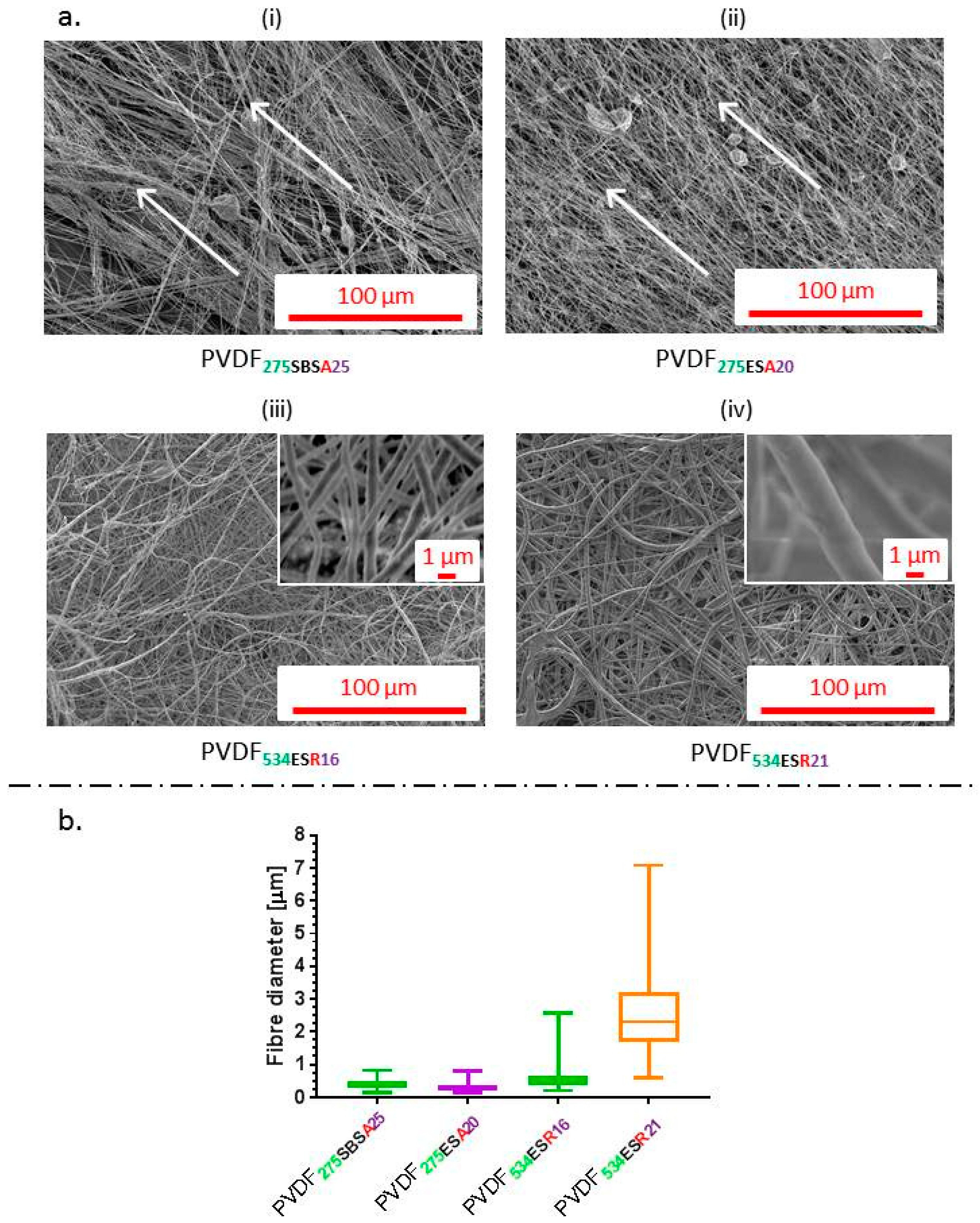
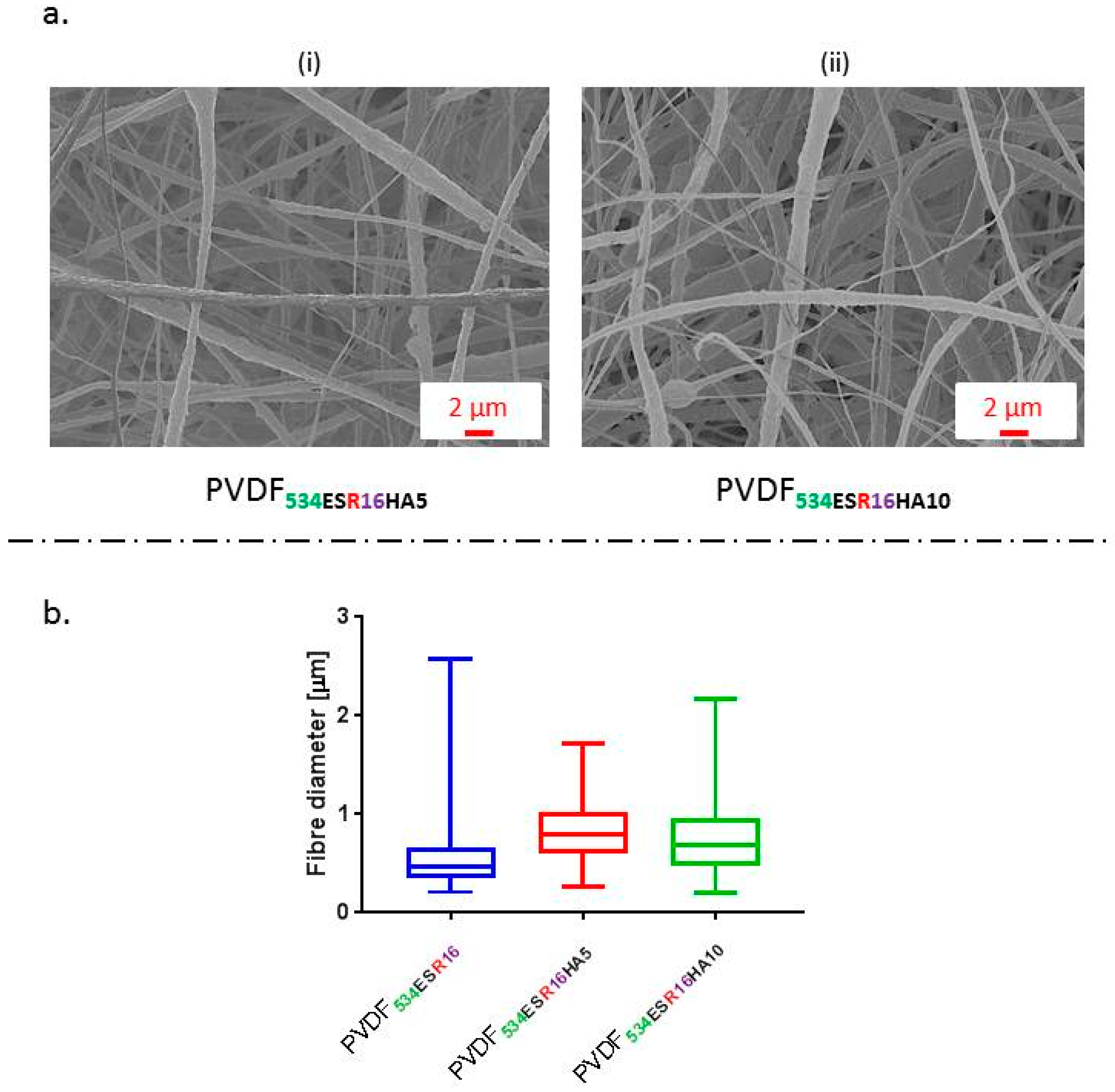
3.3.1. Fibre Morphology, Fibre Diameter and Size Distribution

Fibre morphology was assessed via scanning electron microscopy (SEM; Hitachi high technologies S-3000N, Tokyo, Japan). Fibre mat sections were cut, mounted and sputter coated as previously described [82]. Fibre diameters were determined using ImageJ, (version 1.50i, NIH, Bethesda, Maryland, USA); at least 100 individual fibre diameters were measured per sample type.

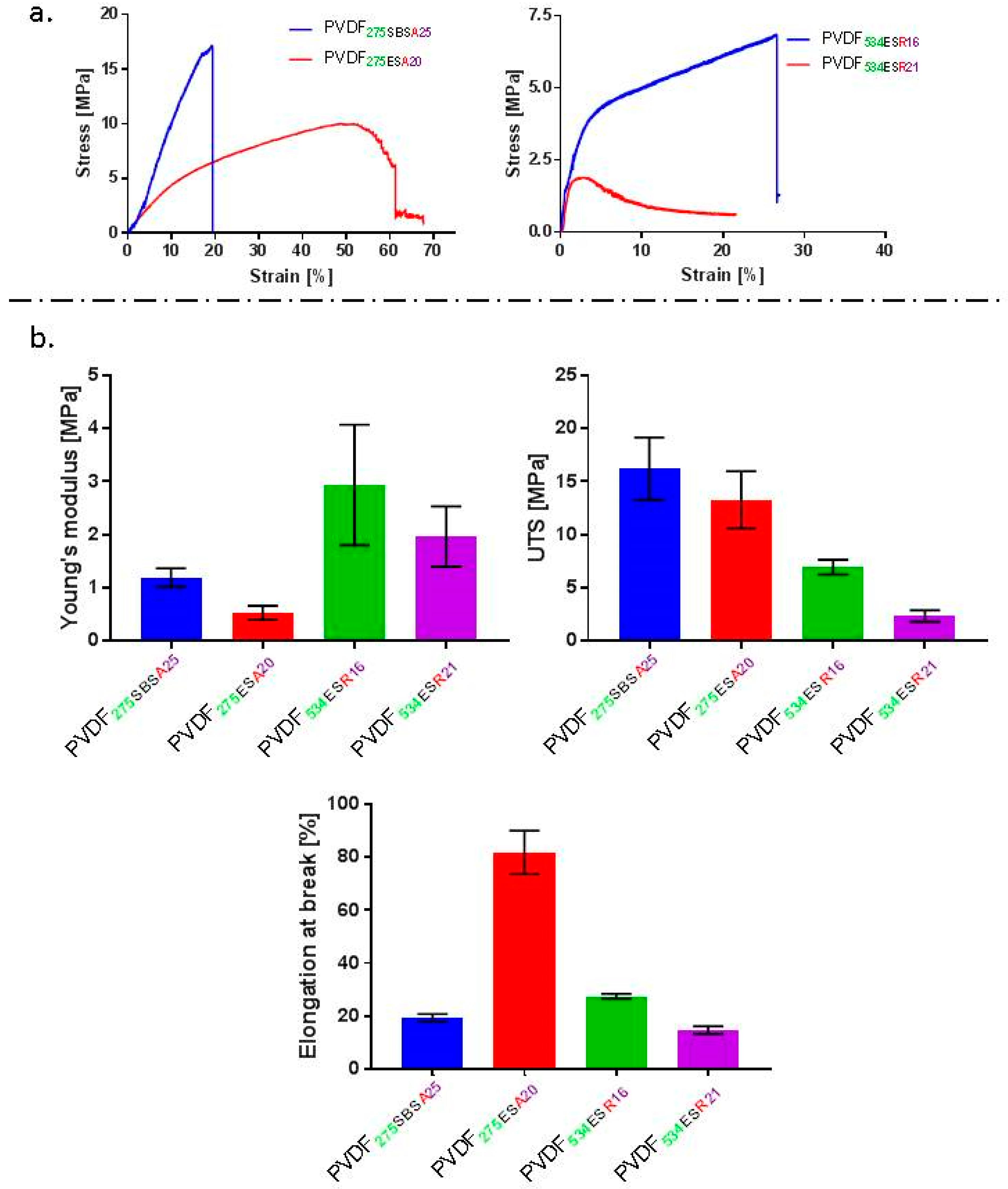
3.3.2. Mechanical Properties of the Fibre Mats

Uniaxial tensile tests were conducted on fibre mats using an Instron 3344 Universal Testing System. Fibres from PVDF275 (aligned) were directly collected on small card frames (windows 30 mm length × 10 mm width, and frame edge 2.5 mm width) while fibre mats from PVDF534 (random) were affixed to bigger frames (windows 45 mm × 20 mm width, and frame edge 5 mm width). The smaller frames were utilised for aligned fibre mats due to difficulties in handling. The ends of fibre mats were taped on to the frames using double-sided tape and a card tab was taped over the double-sided tape to provide better grip and avoid failure due to stress from the clamps [85]. The effective dimensions of tested fibre mats were 20 mm length × 5 mm width (small frames) and 25 mm length × 10 mm width (large frames). Frame edges were cut prior to mechanical testing of the fibre mats. All samples (n = 6 per sample type) were tested at 2 mm min−1 using a 10 N load cell [85]. Force-extension data was recorded during measurement and stress was calculated using equation (1) given below, to assess the effective solid content. The ultimate tensile strength (UTS), Young’s modulus and percentage elongation at break were recorded for each fibre mat type.
S t r e s s = F o r c e A s
where A is the area of the cross-section of the fibre mat and s is the effective solid polymer content calculated as (1 − porosity).
Porosity measurements were conducted on the fibre mats in order to determine stress (due to solid content) and piezoelectric voltage per unit material (described further below). Fibre mats were cut into rectangular samples with a specific size (see above). These mats were weighed and their average thickness determined by measuring with a digital micrometre (in three places). Porosity was determined using Equation (2) below ([86]):
P o r o s i t y   % = ( 1   ( M s ρ V s ) )   ×   100
where Ms is the mass of fibre membrane of a given size, ρ is the density of PVDF and Vs is the volume (fibres + void spaces) of the sample calculated by multiplying length, width and average thickness (thickness measured at three different points on the mat) of the fibre mats before mounting them on window frames for mechanical testing.

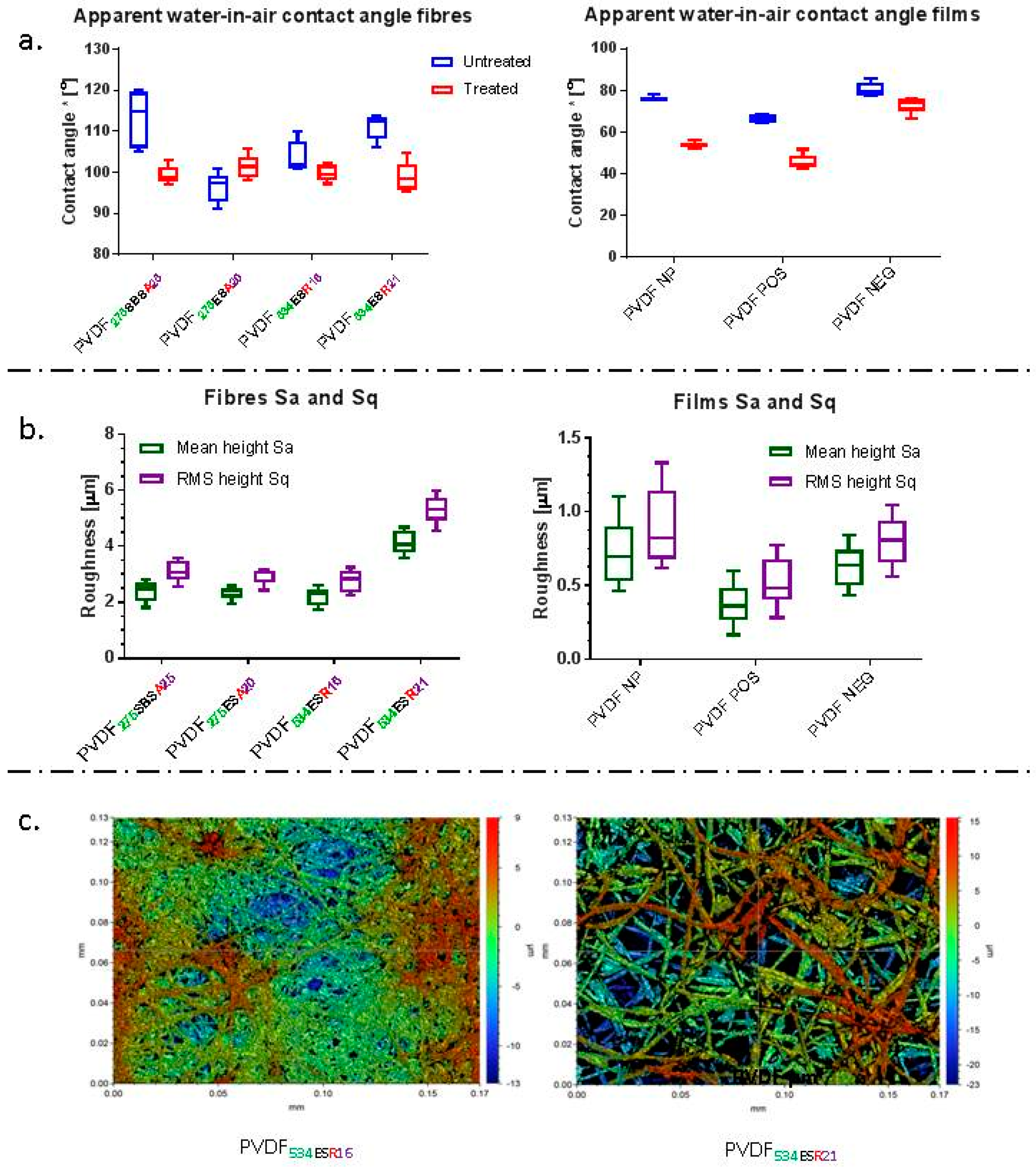
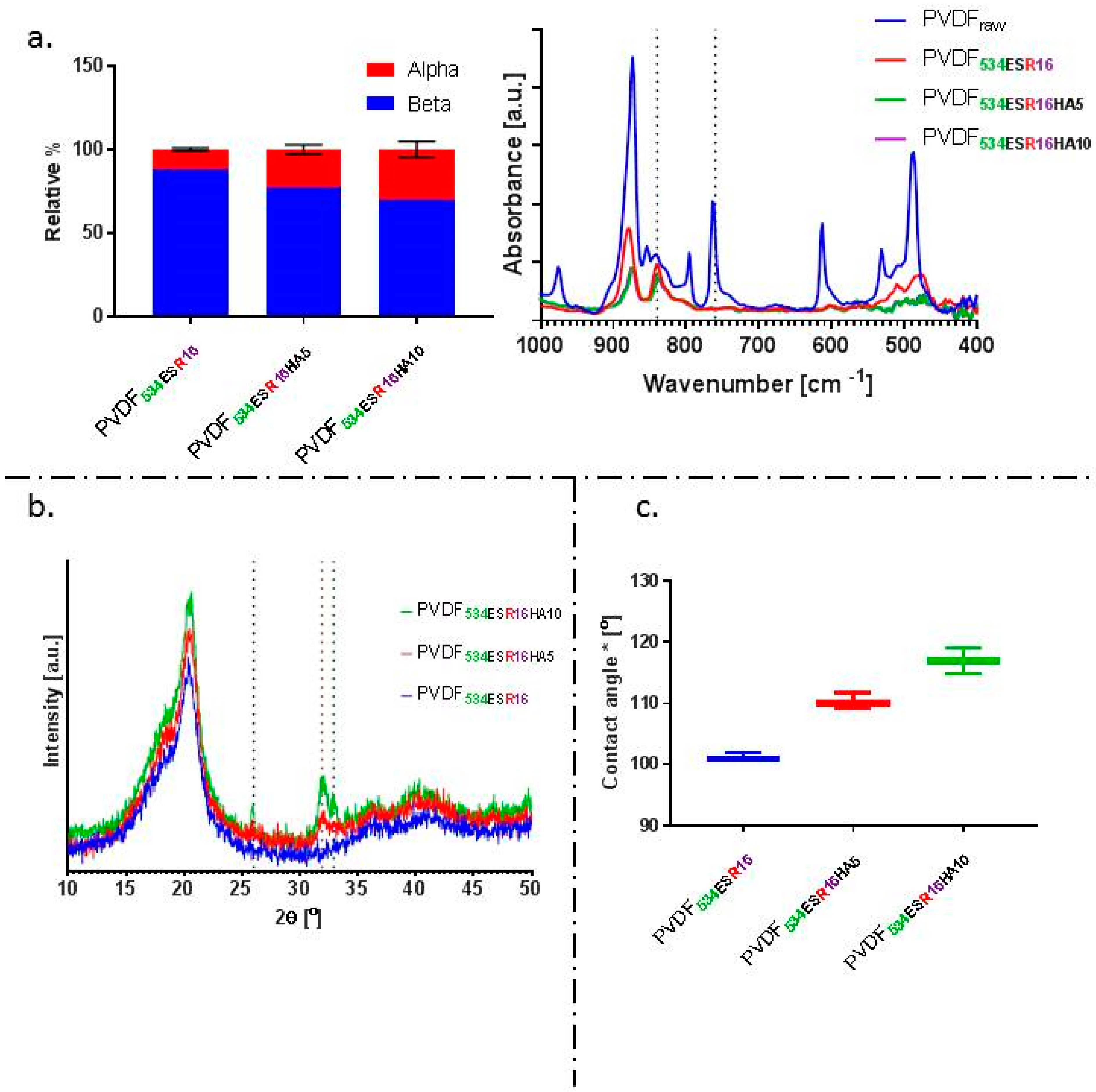
3.3.3. Wettability of the Fibre Mats by Water-in-Air Contact Angle Analysis

Static contact angle measurements were conducted using a Krüss Drop Shape Analyzer (DSA 100). At least 10 different measurements were performed per sample type, with and without exposure to cell culture medium and drying (treated fibres). Contact angle values were recorded over time (up to 1 min) and the values observed at t < 5 s were utilised for all sample types. Cell culture media were prepared by supplementing minimum essential media (MEM-α, Sigma Aldrich, UK) with 10% foetal bovine serum and 1% each of L-glutamine and antibiotic-antimycotic solution. PVDF films and fibre mats were affixed to glass coverslips (12 × 12 mm) using adhesive (commercial silicone sealant, Dow Corning 732) to ensure that the substrates were flat; care was taken to ensure that the adhesive did not influence the contact angle (e.g., membranes of sufficient thickness). Pre-conditioned substrates (treated) were soaked in ethanol for one hour. Ethanol was removed and the treatment was followed by overnight conditioning in cell culture media. This pre-treatment approach was followed in order to imitate the procedures used in preparation for cell culture. Substrates used without the above treatment are referred to as untreated substrates.

3.3.4. Surface Roughness Determination by Optical Profilometry

Optical profilometry was used to determine the roughness of the fibre mats, known to influence the initial adhesion and spreading of cells [38,87]. A Contour GT-K1 white light interferometer (Bruker, Massachusetts, United States) was used in vertical scanning interferometry (VSI) mode. Samples were prepared as described above in Section 3.3.3. Mean surface mean height (Sa) and root mean square height (Sq) were calculated using Vision64 analytical software. A total of 10 images were taken per sample type (analysed area for each image: 170 μm × 130 μm for fibres and 90 μm × 65 μm for films), analysis was conducted on each image, and average values for mean surface mean height (Sa) and root mean square height determined for each sample type.

3.3.5. Determination of Electroactive Phase by ATR-FTIR Analysis

Attenuated total reflectance Fourier transform infrared spectroscopy (ATR-FTIR, FTIR Nicolet iS5; Thermo Scientific, UK) was performed to quantify the amount of electroactive phase present in the samples. Each measurement reported is based on 32 scans at 4 cm−1 in the range of wavenumber 400–1500 cm−1. The characteristic peaks for β-phase were at wavenumbers 510, 840 and 1279 cm−1 and those for α- phase were at 408, 532, 614, 766, 795, 855 and 976 cm−1 [65,88]. A method reported in Reference [88] was used to quantify the relative amount of electroactive phase present in the sample, using Equation (3) below.
F E A = A 840 ( K 840 K 766 ) A 766 + A 840   ×   100
where A766 and A840 are the absorbance values at 766 and 840 cm−1, respectively. The values of K766 and K840 (absorption coefficients at respective wavenumbers) are 6.1 × 10⁴ and 7.7 × 104 cm2 mol−1, respectively [88].

3.3.6. X-ray Diffraction Analysis

X-ray diffraction (X-RD) was used to qualitatively validate and assess the formation of electroactive β-phase. X-RD diffraction spectra were obtained using a PANalytical X’Pert PRO X-ray diffractometer with Cu-Kα radiation (wavelength 0.154 nm) operated at 40 kV and 40 mA. Both fibre and film samples were scanned in the 2θ range of 4° to 50° with a step interval of 0.03342°.

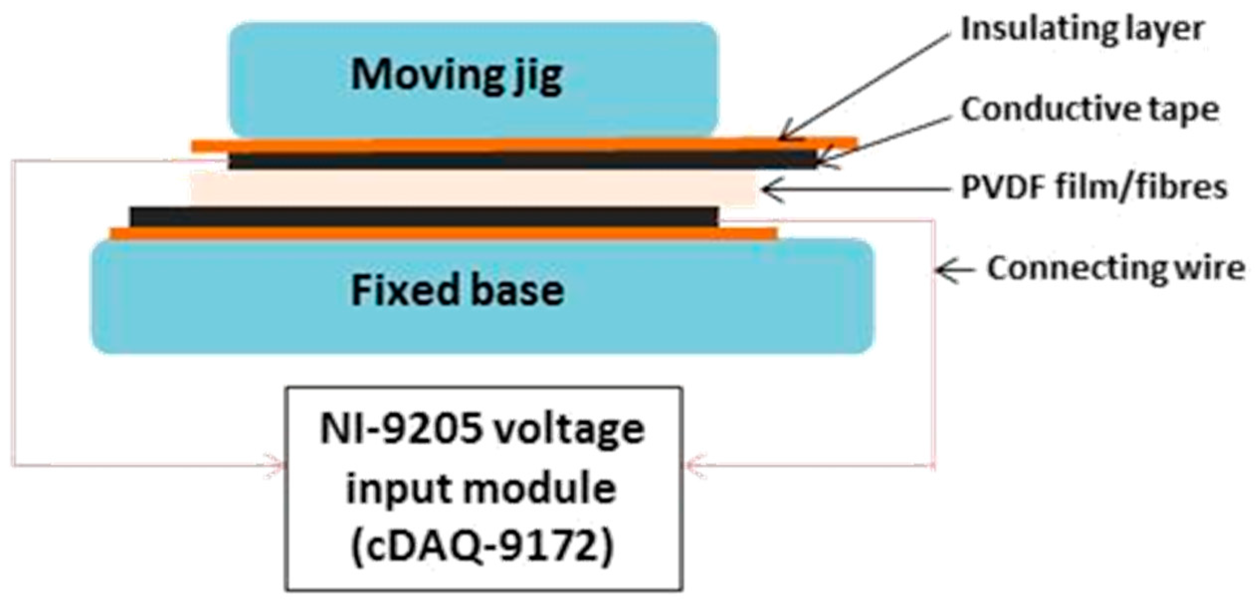
3.3.7. Qualitative Determination of Piezoelectric Characteristics

A rig was constructed to record voltage generated from the piezoelectric materials on mechanical deformation, schemed in Figure 5. A cyclic loading regime of 5 N with a frequency of 4 Hz was applied using an Instron 3344 mechanical testing instrument; similar to approaches previously reported to test the piezoelectric characteristics of PVDF fibre mats [21,34]. Contact surfaces were insulated using electrical insulating tape to ensure that the electrical signals generated were collected and measured efficiently. A voltage input module (NI 9205, National Instruments Corporation (U.K.) Ltd.) was used following manufacturer instructions. Porosity measurements (described above) were utilised to obtain the amount of voltage generated by the effective amount of PVDF present (normalised voltage) in the fibre mats. The normalised voltage values were compared to those obtained for PVDF films. Data was collected using LabVIEW software and cyclic voltage response was re-plotted using GraphPad Prism (Version 7.04).

3.3.8. Thermal Characterisation

Differential scanning calorimetry (DSC) measurements were performed on films, fibres and raw PVDF to determine the effect of processing on melt temperature (Tm) and crystallinity. A heat–cool–heat regime was applied, from room temperature to 200 °C at 10 °C min−1, then cooled to −50 °C at the same rate, and reheated as aforementioned. The degree of crystallinity (ΔXc) of each sample is directly proportional to the value of enthalpies (ΔHm) obtained [89]. Equation (4) was used to calculate the percentage crystallinity of the samples.
Δ X C =   Δ H m x   Δ H α + y   Δ H β
where ΔHm is the melting enthalpy of the sample, ΔHα (93.07 J g−1) and ΔHβ (103.4 J g−1) are the melting enthalpies for samples in 100% α- and β- phase, respectively [89]; x and y indicate the fractional content of respective phases in the sample.
The melting enthalpy for composite HA/PVDF fibres was calculated using Equation (5). The melting enthalpy was corrected for the amount of PVDF present in composite scaffolds by dividing it by the weight fraction (w) of the polymer present [90,91].
Δ X C =   ( ( Δ H m ) / w ) x   Δ H α + y   Δ H β

4. Conclusion

In this work, solution blow spinning and electrospinning have been used to fabricate PVDF fibrous membranes, consisting of different target fibre diameters. The piezoelectric β-phase of fibres has been investigated and compared to that of PVDF films. A comparison across batches of fibres fabricated has been performed to test the reproducibility of the fibres. Fibre mat physical properties were also characterised and important aspects such as roughness and wettability were assessed with respect to future application in cell culture. The piezoelectric characteristics of fibre membranes have qualitatively been demonstrated by measuring the voltage output obtained in response to mechanical deformation.
Comparison of the characteristics of stimuli responsive PVDF fibres showed that solution blow spinning enabled higher fibre production rates of >300% than electrospinning and also higher β-phase content in the fabricated fibres. Electrospinning was shown to have lower variation in the amount of β-phase in a batch-to-batch analysis and enabled a wider range of fibre diameters (mean diameter of ~550 nm to ~2.5 μm) to be targeted and spun. Stimuli responsive piezoelectric characteristics alongside quantification of crystallinity and electroactive phase elucidated the effect of spinning technique and parameters on these properties. Successful inclusion of the known piezoelectric ceramic and bioactive phase, hydroxyapatite, at 5 wt.% and 10 wt.% within the fibres was achieved. This study provides insight into the important considerations to be made in spinning PVDF fibres and bioactive phase loaded PVDF and their properties, towards application in tissue engineering.

Supplementary Materials

The Supplementary Materials are available online.

Author Contributions

B.T. and P.K. performed the experiments. B.T., J.J.B. and S.H.C. contributed to experimental design and concept, manuscript structuring and drafting. R.T.O. provided valuable feedback and helped in improving the structure and content of the manuscript.

Funding

This research was partially funded by Engineering and Physical Sciences Research Council (EPSRC) grant number [EP/I02249X/1].

Acknowledgments

The authors acknowledge support from the Engineering and Physical Sciences Research Council (EPSRC) (EP/I02249X/1). BT would like to thank the Commonwealth scholarship commission for PhD funding. The authors acknowledge Soheyla Ostovar for providing hydroxyapatite, as well as Stephen Quinn and Tatiana Nascimento for their helpful discussions.

Conflicts of Interest

The authors declare no conflict of interest.

References

  1. De las Heras Alarcón, C.; Pennadam, S.; Alexander, C. Stimuli responsive polymers for biomedical applications. Chem. Soc. Rev. 2005, 34, 276–285. [Google Scholar] [CrossRef] [PubMed]
  2. Cabane, E.; Zhang, X.; Langowska, K.; Palivan, C.G.; Meier, W. Stimuli-responsive polymers and their applications in nanomedicine. Biointerphases 2012, 7, 1–27. [Google Scholar] [CrossRef] [PubMed]
  3. Tandon, B.; Magaz, A.; Balint, R.; Blaker, J.J.; Cartmell, S.H. Electroactive biomaterials: Vehicles for controlled delivery of therapeutic agents for drug delivery and tissue regeneration. Adv. Drug Deliv. Rev. 2018, 129, 148–168. [Google Scholar] [CrossRef] [PubMed]
  4. Uǧur, G.; Chang, J.; Xiang, S.; Lin, L.; Lu, J. A near-infrared mechano responsive polymer system. Adv. Mater. 2012, 24, 2685–2690. [Google Scholar] [CrossRef]
  5. Cardoso, V.F.; Correia, D.M.; Ribeiro, C.; Fernandes, M.M.; Lanceros-Méndez, S. Fluorinated polymers as smart materials for advanced biomedical applications. Polymers 2018, 10, 161. [Google Scholar] [CrossRef]
  6. Hsu, C.C.; Wu, C.S.; Liu, Y.L. Multiple stimuli-responsive poly(vinylidene fluoride) (PVDF) membrane exhibiting high efficiency of membrane clean in protein separation. J. Memb. Sci. 2014, 450, 257–264. [Google Scholar] [CrossRef]
  7. Hoop, M.; Chen, X.-Z.; Ferrari, A.; Mushtaq, F.; Ghazaryan, G.; Tervoort, T.; Poulikakos, D.; Nelson, B.; Pane, S. Ultrasound-mediated piezoelectric differentiation of neuron-like PC12 cells on PVDF membranes. Sci. Rep. 2017, 7, 4028. [Google Scholar] [CrossRef]
  8. Damaraju, S.M.; Shen, Y.; Elele, E.; Khusid, B.; Eshghinejad, A.; Li, J.; Jaffe, M.; Arinzeh, T.L. Three-dimensional piezoelectric fibrous scaffolds selectively promote mesenchymal stem cell differentiation. Biomaterials 2017, 149, 51–62. [Google Scholar] [CrossRef]
  9. Ribeiro, C.; Pärssinen, J.; Sencadas, V.; Correia, V.; Miettinen, S.; Hytönen, V.P.; Lanceros-Méndez, S. Dynamic piezoelectric stimulation enhances osteogenic differentiation of human adipose stem cells. J. Biomed. Mater. Res. Part A 2015, 103, 2172–2175. [Google Scholar] [CrossRef]
  10. Tandon, B.; Blaker, J.J.; Cartmell, S.H. Piezoelectric materials as stimulatory biomedical materials and scaffolds for bone repair. Acta Biomater. 2018, 73, 1–20. [Google Scholar] [CrossRef]
  11. Dubey, A.K.; Kinoshita, R.; Kakimoto, K.I. Piezoelectric sodium potassium niobate mediated improved polarization and in vitro bioactivity of hydroxyapatite. RSC Adv. 2015, 5, 19638–19646. [Google Scholar] [CrossRef]
  12. Bowen, C.R.; Raman, K.V.S.; Topolov, V.Y. Piezoelectric Composites Based on Hydroxyapatite/Barium Titanate. Adv. Sci. Technol. 2009, 54, 1–6. [Google Scholar] [CrossRef]
  13. Tang, Y.; Wu, C.; Wu, Z.; Hu, L.; Zhang, W.; Zhao, K. Fabrication and in vitro biological properties of piezoelectric bioceramics for bone regeneration. Sci. Rep. 2017, 7, 43360. [Google Scholar] [CrossRef] [PubMed]
  14. Zhang, Y.; Chen, L.; Zeng, J.; Zhou, K.; Zhang, D. Aligned porous barium titanate/hydroxyapatite composites with high piezoelectric coefficients for bone tissue engineering. Mater. Sci. Eng. C 2014, 39, 143–149. [Google Scholar] [CrossRef] [PubMed]
  15. Denchai, A.; Tartarini, D.; Mele, E. Cellular Response to Surface Morphology: Electrospinning and Computational Modeling. Front. Bioeng. Biotechnol. 2018, 6, 1–11. [Google Scholar] [CrossRef]
  16. Loh, Q.L.; Choong, C. Three-Dimensional Scaffolds for Tissue Engineering Applications: Role of Porosity and Pore Size. Tissue Eng. Part B Rev. 2013, 19, 485–502. [Google Scholar] [CrossRef]
  17. Ding, B.; Wang, M.; Wang, X.; Yu, J.; Sun, G. Electrospun nanomaterials for ultrasensitive sensors. Mater. Today 2010, 13, 16–27. [Google Scholar] [CrossRef]
  18. Mercante, L.A.; Scagion, V.P.; Migliorini, F.L.; Mattoso, L.H.C.; Correa, D.S. Electrospinning-based (bio)sensors for food and agricultural applications: A review. TrAC Trends Anal. Chem. 2017, 91, 91–103. [Google Scholar] [CrossRef]
  19. Gopal, R.; Kaur, S.; Feng, C.Y.; Chan, C.; Ramakrishna, S.; Tabe, S.; Matsuura, T. Electrospun nanofibrous polysulfone membranes as pre-filters: Particulate removal. J. Memb. Sci. 2007, 289, 210–219. [Google Scholar] [CrossRef]
  20. Motamedi, A.S.; Mirzadeh, H.; Hajiesmaeilbaigi, F.; Bagheri-Khoulenjani, S.; Shokrgozar, M. Effect of electrospinning parameters on morphological properties of PVDF nanofibrous scaffolds. Prog. Biomater. 2017, 6, 113–123. [Google Scholar] [CrossRef] [PubMed]
  21. Jiyong, H.; Yuanyuan, G.; Hele, Z.; Yinda, Z.; Xudong, Y. Effect of electrospinning parameters on piezoelectric properties of electrospun PVDF nanofibrous mats under cyclic compression. J. Text. Inst. 2018, 109, 843–850. [Google Scholar] [CrossRef]
  22. Mokhtari, F.; Latifi, M.; Shamshirsaz, M. Electrospinning/electrospray of polyvinylidene fluoride (PVDF): Piezoelectric nanofibers. J. Text. Inst. 2016, 107, 1037–1055. [Google Scholar] [CrossRef]
  23. Damaraju, S.M.; Wu, S.; Jaffe, M.; Arinzeh, T.L. Structural changes in PVDF fibers due to electrospinning and its effect on biological function. Biomed. Mater. 2013, 8. [Google Scholar] [CrossRef] [PubMed]
  24. Medeiros, E.S.; Glenn, G.M.; Klamczynski, A.P.; Orts, W.J.; Mattoso, L.H.C. Solution blow spinning: A new method to produce micro- and nanofibers from polymer solutions. J. Appl. Polym. Sci. 2009, 113, 2322–2330. [Google Scholar] [CrossRef]
  25. Behrens, A.M.; Casey, B.J.; Sikorski, M.J.; Wu, K.L.; Tutak, W.; Sandler, A.D.; Kofinas, P. In situ deposition of PLGA nanofibers via solution blow spinning. ACS Macro Lett. 2014, 3, 249–254. [Google Scholar] [CrossRef]
  26. Daristotle, J.L.; Behrens, A.M.; Sandler, A.D.; Kofinas, P. A Review of the Fundamental Principles and Applications of Solution Blow Spinning. ACS Appl. Mater. Interfaces 2016, 8, 34951–34963. [Google Scholar] [CrossRef] [PubMed]
  27. Wang, D.; Sun, G.; Chiou, B. Sen A high-throughput, controllable, and environmentally benign fabrication process of thermoplastic nanofibers. Macromol. Mater. Eng. 2007, 292, 407–414. [Google Scholar] [CrossRef]
  28. Oliveira, J.E.; Mattoso, L.H.C.; Orts, W.J.; Medeiros, E.S. Structural and morphological characterization of micro and nanofibers produced by electrospinning and solution blow spinning: A comparative study. Adv. Mater. Sci. Eng. 2013, 2013. [Google Scholar] [CrossRef]
  29. Zhuang, X.; Shi, L.; Jia, K.; Cheng, B.; Kang, W. Solution blown nanofibrous membrane for microfiltration. J. Memb. Sci. 2013, 429, 66–70. [Google Scholar] [CrossRef]
  30. Bolbasov, E.N.; Anissimov, Y.G.; Pustovoytov, A.V.; Khlusov, I.A.; Zaitsev, A.A.; Zaitsev, K.V.; Lapin, I.N.; Tverdokhlebov, S.I. Ferroelectric polymer scaffolds based on a copolymer of tetrafluoroethylene with vinylidene fluoride: Fabrication and properties. Mater. Sci. Eng. C 2014, 40, 32–41. [Google Scholar] [CrossRef] [PubMed]
  31. Li, Z.; Wang, C. Effects of Working Parameters on Electrospinning; Springer: Berlin/Heidelberg, Germany, 2013; pp. 15–28. ISBN 978-3-642-36426-6. [Google Scholar]
  32. Li, Q.; Xi, S.; Zhang, X. Conservation of paper relics by electrospun PVDF fiber membranes. J. Cult. Herit. 2014, 15, 359–364. [Google Scholar] [CrossRef]
  33. Zaarour, B.; Zhu, L.; Jin, X. Controlling the surface structure, mechanical properties, crystallinity, and piezoelectric properties of electrospun PVDF nanofibers by maneuvering molecular weight. Soft Mater. 2019, 17, 181–189. [Google Scholar] [CrossRef]
  34. Shao, H.; Fang, J.; Wang, H.; Lin, T. Effect of electrospinning parameters and polymer concentrations on mechanical-to-electrical energy conversion of randomly-oriented electrospun poly(vinylidene fluoride) nanofiber mats. RSC Adv. 2015, 5, 14345–14350. [Google Scholar] [CrossRef]
  35. Li, T.-T.; Ebert, K.; Vogel, J.; Groth, T. Comparative studies on osteogenic potential of micro- and nanofibre scaffolds prepared by electrospinning of poly(ε-caprolactone). Prog. Biomater. 2013, 2, 13. [Google Scholar] [CrossRef]
  36. Takahashi, Y.; Tabata, Y. Effect of the fiber diameter and porosity of non-woven PET fabrics on the osteogenic differentiation of mesenchymal stem cells. J. Biomater. Sci. Polym. Ed. 2004, 15, 41–57. [Google Scholar] [CrossRef]
  37. Badami, A.S.; Kreke, M.R.; Thompson, M.S.; Riffle, J.S.; Goldstein, A.S. Effect of fiber diameter on spreading, proliferation, and differentiation of osteoblastic cells on electrospun poly(lactic acid) substrates. Biomaterials 2006, 27, 596–606. [Google Scholar] [CrossRef]
  38. Guimaires, A.; Martins, A.; Pinho, E.D.; Faria, S.; Reis, R.L.; Neves, N.M. Solving cell infiltration limitations of electrospun nanofiber meshes for tissue engineering applications. Nanomedicine 2010, 5, 539–554. [Google Scholar] [CrossRef]
  39. Kiselev, P.; Rosell-Llompart, J. Highly aligned electrospun nanofibers by elimination of the whipping motion. J. Appl. Polym. Sci. 2012, 125, 2433–2441. [Google Scholar] [CrossRef]
  40. Lei, T.; Yu, L.; Zheng, G.; Wang, L.; Wu, D.; Sun, D. Electrospinning-induced preferred dipole orientation in PVDF fibers. J. Mater. Sci. 2015, 50, 4342–4347. [Google Scholar] [CrossRef]
  41. Yu, L.; Wang, S.; Li, Y.; Chen, D.; Liang, C.; Lei, T.; Sun, D.; Zhao, Y.; Wang, L. Piezoelectric performance of aligned PVDF nanofibers fabricated by electrospinning and mechanical spinning. Proc. IEEE Conf. Nanotechnol. 2013, 962–966. [Google Scholar]
  42. Yu, J.H.; Fridrikh, S.V.; Rutledge, G.C. The role of elasticity in the formation of electrospun fibers. Polymer (Guildf) 2006, 47, 4789–4797. [Google Scholar] [CrossRef]
  43. Moradi, R.; Karimi-Sabet, J.; Shariaty-Niassar, M.; Koochaki, M.A. Preparation and characterization of polyvinylidene fluoride/graphene superhydrophobic fibrous films. Polymers (Basel) 2015, 7, 1444–1463. [Google Scholar] [CrossRef]
  44. Awanis Hashim, N.; Liu, Y.; Li, K. Stability of PVDF hollow fibre membranes in sodium hydroxide aqueous solution. Chem. Eng. Sci. 2011, 66, 1565–1575. [Google Scholar] [CrossRef]
  45. Torres-Sanchez, C.; Al Mushref, F.R.A.; Norrito, M.; Yendall, K.; Liu, Y.; Conway, P.P. The effect of pore size and porosity on mechanical properties and biological response of porous titanium scaffolds. Mater. Sci. Eng. C 2017, 77, 219–228. [Google Scholar] [CrossRef]
  46. Cao, Y.; Shibata, S.; Fukumoto, I. Mechanical properties of biodegradable composites reinforced with bagasse fibre before and after alkali treatments. Compos. Part A Appl. Sci. Manuf. 2006, 37, 423–429. [Google Scholar] [CrossRef]
  47. Bolbasov, E.N.; Stankevich, K.S.; Sudarev, E.A.; Bouznik, V.M.; Kudryavtseva, V.L.; Antonova, L.V.; Matveeva, V.G.; Anissimov, Y.G.; Tverdokhlebov, S.I. The investigation of the production method influence on the structure and properties of the ferroelectric nonwoven materials based on vinylidene fluoride—Tetrafluoroethylene copolymer. Mater. Chem. Phys. 2016, 182, 338–346. [Google Scholar] [CrossRef]
  48. Denning, D.; Guyonnet, J.; Rodriguez, B.J. Applications of piezoresponse force microscopy in materials research: From inorganic ferroelectrics to biopiezoelectrics and beyond. Int. Mater. Rev. 2016, 61, 46–70. [Google Scholar] [CrossRef]
  49. Zhou, F.L.; Wu, H.H.; McHugh, D.J.; Wimpenny, I.; Zhang, X.; Gough, J.E.; Hubbard Cristinacce, P.L.; Parker, G.J.M. Co-electrospraying of tumour cell mimicking hollow polymeric microspheres for diffusion magnetic resonance imaging. Mater. Sci. Eng. C 2019, 101, 217–227. [Google Scholar] [CrossRef]
  50. Sigal, G.B.; Mrksich, M.; Whitesides, G.M. Effect of surface wettability on the adsorption of proteins and detergents. J. Am. Chem. Soc. 1998, 120, 3464–3473. [Google Scholar] [CrossRef]
  51. Zhang, Z.; Wu, X.; Wang, L.; Zhao, B.; Li, J.; Zhang, H. Wetting mechanism of a PVDF hollow fiber membrane in immersed membrane contactors for CO2 capture in the presence of monoethanolamine. RSC Adv. 2017, 7, 13451–13457. [Google Scholar] [CrossRef]
  52. Prince, J.A.; Singh, G.; Rana, D.; Matsuura, T.; Anbharasi, V.; Shanmugasundaram, T.S. Preparation and characterization of highly hydrophobic poly(vinylidene fluoride)—Clay nanocomposite nanofiber membranes (PVDF-clay NNMs) for desalination using direct contact membrane distillation. J. Memb. Sci. 2012, 397–398, 80–86. [Google Scholar] [CrossRef]
  53. Gopal, R.; Kaur, S.; Ma, Z.; Chan, C.; Ramakrishna, S.; Matsuura, T. Electrospun nanofibrous filtration membrane. J. Memb. Sci. 2006, 281, 581–586. [Google Scholar] [CrossRef]
  54. Amirikia, M.; Shariatzadeh, S.M.A.; Jorsaraei, S.G.A.; Soleimani Mehranjani, M. Impact of pre-incubation time of silk fibroin scaffolds in culture medium on cell proliferation and attachment. Tissue Cell 2017, 49, 657–663. [Google Scholar] [CrossRef]
  55. Ottosson, M.; Jakobsson, A.; Johansson, F. Accelerated wound closure—Differently organized nanofibers affect cell migration and hence the closure of artificial wounds in a cell based in vitro model. PLoS One 2017, 12, 1–15. [Google Scholar] [CrossRef] [PubMed]
  56. Szewczyk, P.K.; Ura, D.P.; Metwally, S.; Knapczyk-Korczak, J.; Gajek, M.; Marzec, M.M.; Bernasik, A.; Stachewicz, U. Roughness and fiber fraction dominated wetting of electrospun fiber-based porous meshes. Polymers (Basel) 2018, 11, 34. [Google Scholar] [CrossRef] [PubMed]
  57. Kang, M.; Jung, R.; Kim, H.S.; Jin, H.J. Preparation of superhydrophobic polystyrene membranes by electrospinning. Colloids Surfaces A Physicochem. Eng. Asp. 2008, 313–314, 411–414. [Google Scholar] [CrossRef]
  58. Agarwal, S.; Horst, S.; Bognitzki, M. Electrospinning of fluorinated polymers: Formation of superhydrophobic surfaces. Macromol. Mater. Eng. 2006, 291, 592–601. [Google Scholar] [CrossRef]
  59. Correia, D.M.; Ribeiro, C.; Sencadas, V.; Botelho, G.; Carabineiro, S.A.C.; Ribelles, J.L.G.; Lanceros-Méndez, S. Influence of oxygen plasma treatment parameters on poly(vinylidene fluoride) electrospun fiber mats wettability. Prog. Org. Coatings 2015, 85, 151–158. [Google Scholar] [CrossRef]
  60. Recek, N.; Resnik, M.; Motaln, H.; Lah-Turnšek, T.; Augustine, R.; Kalarikkal, N.; Thomas, S.; Mozetič, M. Cell Adhesion on Polycaprolactone Modified by Plasma Treatment. Int. J. Polym. Sci. 2016, 2016. [Google Scholar] [CrossRef]
  61. Duque Sánchez, L.; Brack, N.; Postma, A.; Pigram, P.J.; Meagher, L. Surface modification of electrospun fibres for biomedical applications: A focus on radical polymerization methods. Biomaterials 2016, 106, 24–45. [Google Scholar] [CrossRef] [PubMed]
  62. Ribeiro, C.; Panadero, J.A.; Sencadas, V.; Lanceros-Méndez, S.; Tamaño, M.N.; Moratal, D.; Salmerón-Sánchez, M.; Gómez Ribelles, J.L. Fibronectin adsorption and cell response on electroactive poly(vinylidene fluoride) films. Biomed. Mater. 2012, 7. [Google Scholar] [CrossRef] [PubMed]
  63. González-Benito, J.; Teno, J.; González-Gaitano, G.; Xu, S.; Chiang, M.Y. PVDF/TiO2 nanocomposites prepared by solution blow spinning: Surface properties and their relation with S. Mutans adhesion. Polym. Test. 2017, 58, 21–30. [Google Scholar] [CrossRef]
  64. Huang, F.; Wei, Q.; Cai, Y.; Wu, N. Surface structures and contact angles of electrospun poly(vinylidene fluoride) nanofiber membranes. Int. J. Polym. Anal. Charact. 2008, 13, 292–301. [Google Scholar] [CrossRef]
  65. Martins, P.; Lopes, A.C.; Lanceros-Mendez, S. Electroactive phases of poly(vinylidene fluoride): Determination, processing and applications. Prog. Polym. Sci. 2014, 39, 683–706. [Google Scholar] [CrossRef]
  66. Haponska, M.; Trojanowska, A.; Nogalska, A.; Jastrzab, R.; Gumi, T.; Tylkowski, B. PVDF membrane morphology—Influence of polymer molecularweight and preparation temperature. Polymers (Basel) 2017, 9, 718. [Google Scholar] [CrossRef] [PubMed]
  67. Chinaglia, D.L.; Gregorio, R.; Stefanello, J.C.; Pisani Altafim, R.A.; Wirges, W.; Wang, F.; Gerhard, R. Influence of the solvent evaporation rate on the crystalline phases of solution-cast poly(vinylidene fluoride) films. J. Appl. Polym. Sci. 2010, 43, 785–791. [Google Scholar] [CrossRef]
  68. Ramasundaram, S.; Yoon, S.; Kim, K.J.; Lee, J.S. Direct preparation of nanoscale thin films of poly(vinylidene fluoride) containing β-crystalline phase by heat-controlled spin coating. Macromol. Chem. Phys. 2008, 209, 2516–2526. [Google Scholar] [CrossRef]
  69. Akbari, A. Formation of Poly (vinylidene fluoride) Nanofibers. J. Nanostructures 2012, 2, 251–256. [Google Scholar]
  70. Milleret, V.; Hefti, T.; Hall, H.; Vogel, V.; Eberli, D. Influence of the fiber diameter and surface roughness of electrospun vascular grafts on blood activation. Acta Biomater. 2012, 8, 4349–4356. [Google Scholar] [CrossRef]
  71. Zhou, Z.; Wu, X.F. Electrospinning superhydrophobic-superoleophilic fibrous PVDF membranes for high-efficiency water-oil separation. Mater. Lett. 2015, 160, 423–427. [Google Scholar] [CrossRef]
  72. Chang, J.J.; Lee, Y.H.; Wu, M.H.; Yang, M.C.; Chien, C.T. Electrospun anti-adhesion barrier made of chitosan alginate for reducing peritoneal adhesions. Carbohydr. Polym. 2012, 88, 1304–1312. [Google Scholar] [CrossRef]
  73. Unnithan, A.R.; Barakat, N.A.M.; Tirupathi Pichiah, P.B.; Gnanasekaran, G.; Nirmala, R.; Cha, Y.S.; Jung, C.H.; El-Newehy, M.; Kim, H.Y. Wound-dressing materials with antibacterial activity from electrospun polyurethane-dextran nanofiber mats containing ciprofloxacin HCl. Carbohydr. Polym. 2012, 90, 1786–1793. [Google Scholar] [CrossRef] [PubMed]
  74. Wu, J.; Hong, Y. Enhancing cell infiltration of electrospun fibrous scaffolds in tissue regeneration. Bioact. Mater. 2016, 1, 56–64. [Google Scholar] [CrossRef]
  75. Phipps, M.C.; Clem, W.C.; Grunda, J.M.; Clines, G.A.; Bellis, S.L. Increasing the pore sizes of bone-mimetic electrospun scaffolds comprised of polycaprolactone, collagen I and hydroxyapatite to enhance cell infiltration. Biomaterials 2012, 33, 524–534. [Google Scholar] [CrossRef] [PubMed]
  76. Liang, D.; Hsiao, B.S.; Chu, B. Functional electrospun nanofibrous scaffolds for biomedical applications. Adv. Drug Deliv. Rev. 2007, 59, 1392–1412. [Google Scholar] [CrossRef] [PubMed]
  77. Zhong, S.; Zhang, Y.; Lim, C.T. Fabrication of Large Pores in Electrospun Nanofibrous Scaffolds for Cellular Infiltration: A Review. Tissue Eng. Part B Rev. 2011, 18, 77–87. [Google Scholar] [CrossRef]
  78. Medeiros, E.L.G.; Braz, A.L.; Porto, I.J.; Menner, A.; Bismarck, A.; Boccaccini, A.R.; Lepry, W.C.; Nazhat, S.N.; Medeiros, E.S.; Blaker, J.J. Porous Bioactive Nanofibers via Cryogenic Solution Blow Spinning and Their Formation into 3D Macroporous Scaffolds. ACS Biomater. Sci. Eng. 2016, 2, 1442–1449. [Google Scholar] [CrossRef]
  79. Joshi, V.S.; Lei, N.Y.; Walthers, C.M.; Wu, B.; Dunn, J.C.Y. Macroporosity enhances vascularization of electrospun scaffolds. J. Surg. Res. 2013, 183, 18–26. [Google Scholar] [CrossRef]
  80. Bowen, C.R.; Gittings, J.; Turner, I.G.; Baxter, F.; Chaudhuri, J.B. Dielectric and piezoelectric properties of hydroxyapatite-BaTiO3composites. Appl. Phys. Lett. 2006, 89, 1–4. [Google Scholar] [CrossRef]
  81. Wang, Y.; Zhu, Y.; Lao, L.; Gao, C.; Zhang, Y. Poly(lactide-co-glycolide)/hydroxyapatite nanofibrous scaffolds fabricated by electrospinning for bone tissue engineering. J. Mater. Sci. Mater. Med. 2011, 22, 1873–1884. [Google Scholar]
  82. Kamyar, N.; Greenhalgh, R.D.; Nascimento, T.R.L.; Medeiros, E.S.; Matthews, P.D.; Nogueira, L.P.; Haugen, H.J.; Lewis, D.J.; Blaker, J.J. Exploiting Inherent Instability of 2D Black Phosphorus for Controlled Phosphate Release from Blow-Spun Poly(lactide- co -glycolide) Nanofibers. ACS Appl. Nano Mater. 2018, 1, 4190–4197. [Google Scholar] [CrossRef]
  83. Braga, F.J.C.; Rogero, S.O.; Couto, A.A.; Marques, R.F.C.; Ribeiro, A.A.; de Carvalho Campos, J.S. Characterization of PVDF/HAP composites for medical applications. Mater. Res. 2007, 10, 247–251. [Google Scholar] [CrossRef]
  84. Gandhi, A.A.; Wojtas, M.; Lang, S.B.; Kholkin, A.L.; Tofail, S.A.M. Piezoelectricity in poled hydroxyapatite ceramics. J. Am. Ceram. Soc. 2014, 97, 2867–2872. [Google Scholar] [CrossRef]
  85. Magaz, A.; Roberts, A.D.; Faraji, S.; Nascimento, T.R.L.; Medeiros, E.S.; Zhang, W.; Greenhalgh, R.D.; Mautner, A.; Li, X.; Blaker, J.J. Porous, Aligned, and Biomimetic Fibers of Regenerated Silk Fibroin Produced by Solution Blow Spinning. Biomacromolecules 2018, 19, 4542–4553. [Google Scholar] [CrossRef]
  86. Lee, B.L.-P.; Tang, Z.; Wang, A.; Huang, F.; Yan, Z.; Wang, D.; Chu, J.S.; Dixit, N.; Yang, L.; Li, S. Synovial stem cells and their responses to the porosity of microfibrous scaffold. Acta Biomater. 2013, 9, 7264–7275. [Google Scholar] [CrossRef] [PubMed]
  87. Nandakumar, A.; Tahmasebi Birgani, Z.; Santos, D.; Mentink, A.; Auffermann, N.; Van Der Werf, K.; Bennink, M.; Moroni, L.; Van Blitterswijk, C.; Habibovic, P. Surface modification of electrospun fibre meshes by oxygen plasma for bone regeneration. Biofabrication 2013, 5. [Google Scholar] [CrossRef] [PubMed]
  88. Cai, X.; Lei, T.; Sun, D.; Lin, L. A critical analysis of the α, β and γ phases in poly(vinylidene fluoride) using FTIR. RSC Adv. 2017, 7, 15382–15389. [Google Scholar] [CrossRef]
  89. Gomes, J.; Nunes, J.S.; Sencadas, V.; Lanceros-Mendez, S. Influence of the β-phase content and degree of crystallinity on the piezo-and ferroelectric properties of poly(vinylidene fluoride). Smart Mater. Struct. 2010, 19. [Google Scholar] [CrossRef]
  90. Walters, M.; Blaker, J.J.; Drouet, M.; Bismarck, A.; Lee, K.-Y. Aligned unidirectional PLA/bacterial cellulose nanocomposite fibre reinforced PDLLA composites. React. Funct. Polym. 2014, 85, 185–192. [Google Scholar]
  91. Lee, K.Y.; Blaker, J.J.; Bismarck, A. Surface functionalisation of bacterial cellulose as the route to produce green polylactide nanocomposites with improved properties. Compos. Sci. Technol. 2009, 69, 2724–2733. [Google Scholar] [CrossRef]
Sample Availability: Samples are not available from the authors.
Figure 1. (a) Scanning electron microscopy (SEM) images of aligned and random fibres obtained using SBS and ES. White arrows represent the direction of alignment. (b) Fibre diameter distribution of the different fibrous membranes fabricated using SBS and ES.
Molecules 24 01903 g001
Figure 2. (a) Representative stress-strain curves for different fibres fabricated using SBS and ES, (b) graphs presenting values calculated for different mechanical properties such as Young’s modulus, ultimate tensile strength (UTS) and elongation at break for fabricated fibres.
Molecules 24 01903 g002
Figure 3. (a) Apparent water-in-air contact angle values obtained for untreated and treated (pre-conditioned with cell culture media and dried) fibre mats and films, * represents apparent water-in-air contact angle (b) Distribution of roughness parameters obtained for fibrous PVDF membranes and PVDF films. (c) Representative optical profilometry images obtained for different samples.
Molecules 24 01903 g003
Figure 4. (a) Batch-to-batch variation of the relative% of α- and β-phase in (i) SBS fibre mats, (ii) ES fibre mats, and (iii) amount of α- and β-phase present in micron and sub-micron ES fibre mats in comparison to raw PVDF. (b) Representative FTIR and X-RD graphs of the different fibre mats fabricated. Vertical dotted lines in FTIR graphs represent the characteristic peaks for α- (760 cm-1) and β- (840 cm-1) phase. A peak shift from ~2θ = 20° to ~2θ = 20.3° and the suppression of peaks at ~2θ = 18.5° and ~2θ = 26.7° determined for the fibre mats is evidence of conversion from α-phase to the electroactive β-phase when the raw polymer is processed into fibres. (c) Piezoelectric voltage response obtained for control PVDF films and comparison to the response obtained for the fibre mats fabricated using PVDF534. A peak-to-peak voltage of 2.25 mV, 33.64 mV, 21.94 mV and 27.24 mV was observed for PVDF NP film, PVDF POL film, PVDF534ESR16 and PVDF534ESR21 fibre mats, all respectively.
Molecules 24 01903 g004
Figure 5. Schematic of the piezoelectric voltage measurement setup.
Molecules 24 01903 g005
Figure 6. (a) SEM images of composite fibre mats obtained by inclusion 5 wt.% (i) and 10 wt.% (ii) HA in PVDF, (b) fibre diameter distribution of the ES composite fibres in comparison to neat PVDF fibres.
Molecules 24 01903 g006
Figure 7. (a) Relative% of α- and β-phase and representative FTIR spectra of electrospun HA/PVDF composite fibre mats. A reduction of β-phase from 88.02% in PVDF534ESR16 fibres to 77% and 70% was observed for PVDF534ESR16HA5 and PVDF534ESR16HA10 composites, respectively. (b) X-RD graphs of the composite fibres obtained. (c) The apparent water-in-air* contact angle of the composite fibre mats obtained.
Molecules 24 01903 g007
Table 1. Summary of polymer solutions and fibre spinning parameters investigated. Note that poly(vinylidene fluoride) PVDF534ESR16 is indicative of PVDF Mw 534 kg mol−1 (in green) spun using electrospinning (spinning technique in black) into random (R in red, as opposed to aligned, A in red) using a 16% w/v solution (in purple).
Spinning Method and PVDF Solution CompositionSolution Flow Rate (μL min−1)Theoretical (dry) Fibre Production Rate (g h−1)Working Distance (cm)Collection Speed Voltage Applied (kV)
Solution blow spun PVDF275SBSA25
in DMF at 25% w/v
751.125301000 rpm (diameter 5 cm); equivalent linear speed 5.236 m s−1, aligned fibresNone
Electrospun PVDF275ESA20
in DMF: acetone (1:1 solvent volume ratio) at 20% w/v
250.315500 rpm (diameter 10 cm); equivalent linear speed 5.236 m s−1, aligned fibres15
Electrospun PVDF534ESR16
in DMF:acetone (1:1 solvent ratio) at 16% w/v
250.2417.550 rpm (diameter 10 cm); equivalent linear speed 0.5236 m s−1, random fibres17.5
Electrospun PVDF534ESR21
in DMF:acetone (1:1 solvent ratio) at 21% w/v
250.31517.550 rpm (diameter 10 cm); equivalent linear speed 0.5236 m s−1, random fibres7.5
Electrospun PVDF534ESR16HA5/10 in DMF:acetone (1:1 solvent ratio) at 16% w/v containing HA at 5 wt.% and 10% wt.% 250.2417.550 rpm (diameter 10 cm); equivalent linear speed 0.5236 m s−1, random fibres17.5
Table 2. Thermal properties of the fibrous membranes and respective raw materials assessed via DSC. Tm and Tc are melting temperature (for 1st and 2nd heating profiles) and the temperature of cold crystallisation, respectively.
MaterialTm (°C) 1stTm (°C) 2ndCrystallinity%Tc (°C)
PVDF pellet175.2173.645.8137.3
PVDF powder159.1159.737.5127.8
PVDF275SBSA25168.6172.045.3141.6
PVDF275ESA20168.3172.342.9142.3
PVDF534ESR16158.5163.742.7130.0
PVDF534ESR21157.4163.845.2129.6
PVDF534ESR16HA5158.9163.836.6135.2
PVDF534ESR16HA10158.9162.138.5134.8
PVDF NP175.5175.444.1151.5
PVDF POL168.1172.045.6149.9

