Modular Crystal Chemistry of Thallium Sulfosalts


Department of Geoscience and Natural Resources Management, University of Copenhagen, 1350 København, Denmark
Minerals 2018, 8(11), 478; https://doi.org/10.3390/min8110478
Submission received: 11 September 2018
/
Revised: 18 October 2018
/
Accepted: 19 October 2018
/
Published: 24 October 2018
(This article belongs to the Special Issue Thallium: Mineralogy, Geochemistry and Ore Processes)
Abstract
:Complex sulfides of thallium with As, Sb, or Bi and with other cations (‘thallium sulfosalts’) are a large group of crystal structures with extreme variability. Incorporation of the large Tl+ cation in them is solved in several different ways: housing of Tl in columns of capped trigonal coordination prisms, which form separate walls in the structure (in different combinations with Pb and/or Sb), regular alternation of large Tl with small cations (As), presence of structural arrays of Tl coordination polyhedra paralleled by arrays of As coordination pyramids with a frequency ratio 1:2, omission derivatives with cavities for Tl accommodation and formation of layer structures with thallium concentrated into separate (inter)layers of different types. The first principle leads to a large family of sartorite homologues and rare lillianite homologues, as well as to the chabournéite group. The second one to the hutchinsonite family, omission derivatives form the routhierite and galkhaite groups, and the 1:2 periodicity ratio principle results in several outstanding structures from different groups. Layer structures consist of two-component and three-component layer combinations. Close cation-cation interactions are present but rare.
1. Introduction
The complex sulfides of thallium with formally trivalent As, Sb, or Bi associated with other cations are structurally perhaps the most complicated group of sulfosalts. The principal factor is the size of the univalent thallium ion, which is larger than lead and larger than bismuth, and is comparable in size to monovalent alkali ions—especially potassium, rubidium and cesium, and to the larger divalent cations, especially barium. Sulfosalts of the latter elements mostly belong to the realm of synthetics because they (and partly thallium itself) are consumed by late magmatic, pegmatitic and metamorphic processes, participating in or directly forming silicates. Monovalent thallium has one substantial difference against these cations—its lone electron pair character, similar to Pb2+ and Bi3+. The relative weakness of this character, however, is apparent when examining the coordination polyhedron of thallium in different sulfosalts.
The large ion radius of Tl precludes its simple incorporation into PbS-like arrays and causes problems even in more tolerant SnS-like arrays. These two arrays determine the structures of many common Tl-free sulfosalts of especially Pb, Sb, Bi, As, Cu and Ag. The size of Tl+ also complicates or prevents formation of the incommensurate interfaces, which are known from these sulfosalts. In a number of cases with higher contents of Tl in the complex sulfide, its structural characteristics remind more of complex silicates of Ba or K than that of the ‘common’ sulfosalts like aikinite, boulangerite or emplectite. This bears additional complication, however, because instead of arrays of silicate coordination tetrahedra, polymerization in these sulfosalts joins MS3 or/and MS5 coordination pyramids which have the cation in an exposed position, and this has a lone electron pair. Different ways in which the large coordination polyhedra of thallium are accommodated in the structure, and the kind of structure which results from this accommodation, will be the principal classification criteria we shall use.
The majority of thallium sulfosalts are sulfo-arsenites, with or without Pb, a product of special and fairly rarely occurring ore solution geochemistry with its cocktail of Tl, As, Pb, Hg and Sb, which certainly is problematic for the communities underneath the weathering outcrop [1]. The opposite happens at the famous locality of Lengenbach (Wallis, Switzerland), where this cocktail upkeeps the local tourist aficionado business. The recent discovery of tsygankoite and vorontsovite is an example that the spectrum of locality types is diversifying and new types and sites of thallium-bearing assemblages are being constantly discovered.
This review profits from a number of analyses and structure determinations which were made by many devoted crystallographers and mineralogists, some of whom are specialists in the Tl containing minerals and compounds. Their individual contributions can best be appreciated when scanning the long list of references and the list of minerals/phases treated, which is given in Table 1. Thallium sulfosalt mineralogy and crystal chemistry was a topic of the overviews by Nowacki et al. [2], Zemann [3], Gržetić & Balić-Žunić [4], as well as of the more detailed analyses of pairs and groups of Tl sulfosalts produced by the cooperation of the current author with Drs. T. Balić-Žunić and P. Berlepsch. Mineral syntheses in the realm of Tl sulfosalts were performed especially by Sobott [5,6,7,8], Gržetić and Moh [9] and other members of the ‘Heidelberg circle’; in lesser volume, also by Balić-Žunić et al. [10] and others. The current review combines the observations obtained from the reanalysis of all published sulfosalt structures with the ideas presented in the above reviews and structure papers.
Except for several very recent structures, the structures analyzed in this contribution were published and collected in the Inorganic Crystal Structure Data file. They were obtained from the data collected by means of single-crystal x-ray diffraction and refined with a good reliability factor.
2. Basic Notions and Categories
The crystal structures of sulfosalts rich in As, Sb and/or Bi, in combination with Pb, Sn2+, eventually smaller amounts of Tl+, Ag and Cu often obey one of the two configurations which became known as the PbS and the SnS archetypes [11,12,13,14]. In the well-known PbS archetype, all cations have octahedral coordination, their coordination octahedra are edge sharing and form the F-centered galena-like (sub)structure. In real structures the motif can be somewhat distorted when different cations are combined in one structure, or when some cations have a moderate lone electron pair (LEP) activity. In the structure which obeys a generalized SnS archetype (Figure 1), the structure is divided into double layers (if the archetype is present as a thick slab, into double-ribbons) which contain cations with short strong bonds, binding the two atomic planes of such a pair together, and weak cation-anion interactions situated between layer pairs. The interspaces host lone electron pairs of cations with strong LEP-activity; these block closer cation-anion interactions and require steric accommodation, usually in form of trigonal prismatic volumes to which the tight cation coordination itself represents a capping ‘square’ pyramid. Thus, a monocapped trigonal coordination prism (CN = 7) is a typical coordination of cations with a pronounced lone electron pair activity in sulfosalts. The details of coordinations and polymerization of adjacent cation polyhedra, differ—that is why we talk about a generalized SnS archetype.
Three-dimensional (3D) development of an archetype structure is rare. Usually, they are developed in form of layers, slabs or rods; the latter two may be interconnected in the form of ‘rod-layers’. These complex elements are then recombined into a structure by means of the operations of ‘unit-cell twinning’: mirror (reflection) twinning, glide-reflection twinning, cyclic twinning, bridging of a pseudotetragonal/pseudohexagonal interface, etc. [14]. A special case are omission derivatives, in which either a cluster of coordination polyhedra was omitted and replaced by a completely new atomic choice and configuration, or just a single cation or anion is missing.
Cations with lone electron pairs (i.e., those that are not engaged in bonding) often congregate in the crystal structure, forming an envelope of a common structural volume into which they extend their lone electron pairs. These configurations (the common LEP volume and the cations forming its ‘skin’) are called lone electron pair micelles, which are typical for the structures based on the SnS archetype. Cases when structure consists of atom groups which orient their LEPs outwards, into surrounding structural space, contain ‘inverted lone electron pair micelles’ [15].
Further useful definitions are as follows:
Isotypes are crystal structures with cations and anions of comparable crystal chemical characteristics, closely comparable coordinates in the structure, closely comparable coordination polyhedra, comparable ratios of, and angles between, crystal axes and identical local point-group symmetries (these are ‘isopointal’), as well as with the same overall space group of symmetry. Homeotypes have one or more of the isotype-defining principles relaxed—e.g., they obey a lower space group of symmetry, have differently distorted coordination polyhedra, contain (partial) atom vacancies, etc.
Accretional homologous series is a series of structures in which the type(s) of building blocks (rods, layers) and the principles that define their mutual relationships remain preserved but the size of these blocks varies incrementally by varying the number of constituting coordination polyhedra in them. The plesiotype series is constituted by members which contain the same type of fundamental blocks (slabs, etc., homologously expanded or not) and display the same general rules of recombination of these blocks. However, different members of the series contain different additional blocks/elements, or details of the building blocks, or of their interconnection, differ from member to member in non-homologous ways. Merotypic series combines two types of blocks (etc.); one type is constant (including its homologous expansion derivatives), whereas the representatives of the alternating set can represent different structure types. More details about the modular nomenclature are in [14,15,16,17].
3. Classification Principles
The sulfide crystal radius of univalent thallium by Shannon [18] is about 1.45 Å for CN = 6, and 1.69 Å for CN = 8. Trivalent thallium has r = 0.90 Å (CN = 4) and 0.96 Å (CN = 6), resulting in a quite different crystal chemistry. Shannon’s value for divalent Pb is 1.27 Å (CN = 6), however, the presence of lone electron pairs makes the definition complicated (two radii: for the strong-bond side and for the LEP side, respectively) [19], or completely irrelevant, as for As and Sb. Crystal radii for tetrahedral Ag, Cu+ and Hg in sulfides [18] are 0.92 Å, 0.635 Å and 0.84 Å, respectively, however, the (2 + 4) coordinations of Hg and Ag have two sets of very different distances. The crystal radius for the anions, compatible with the given cation radii, is 1.70 Å for S and 1.84 Å for Se. Comparing Shannon’s Tl–S value for CN8 (3.39 Å) and that for CN6 (3.15 Å) with the Pb–S values (CN6; 2.95 Å) shows that accommodation of Tl in the structures has problems different from those connected with the incorporation of Pb, Sn2+ and other cations. Tl is a large ‘soft cation’, which sometimes displays one-sidedness because of its LEP.
The spectrum of thallium sulfosalts is very varied; structure types depend on the Tl: cation ratio, types of associated cations, presence or absence of Sb and more. The sulfosalts of thallium can be divided into groups according to the way thallium is structurally accommodated. A large group of structures consists of large slabs, rods or blocks of the two above mentioned archetypal structures, or their combination, joined by structure-building operators, which are based on Tl–Pb(Sb) interplay in columns of bi- and tri-capped trigonal coordination pyramids. Alternation of large Tl with much smaller polyhedra of especially As or Sb in selected structure rows produces another important group of structures. Several structures (often from different groups) are created when pure sequences of Tl polyhedra are paralleled by sequences of As/Sb coordination pyramids, which are then present with doubled frequency (in 1:2 ratio).
Finally, an important cluster of structures are those composed of two (less frequently three) compositionally different component layers in regular alternation, i.e., ‘layer structures’, in which the layers share the boundary anions. The component layers are of rather variable architecture, dictated by the cations present and their percentages. The thallium-free layers/portions of the layer structures can then be compared/classified using the degree of lone-electron pair activity and distribution of spaces filled by lone electron pairs (LEP) of As and Sb in them, types of aggregates formed by AsS3 groups, presence or absence of channels hosting other cations, etc. The other criterion is the architecture of thallium containing layers. The most important difference in the space and wall architecture is the difference between the Tl-layers in which thallium is distributed in the layer volume and those, in which it lines the walls of the layer-like interspace; combined cases occur as well.
Below, individual phases/minerals are assembled in groups according to their structural properties, and their characteristic and/or interesting details are described. Sometimes, the structure follows more than one principle, complicating this approach somewhat. This part will be followed by general conclusions, and a critical look at the selected aspects of their crystal chemistry and classification.
4. The ‘Classical’ Sulfosalt Archetypes: SnS Archetype
4.1. Lorándite and Weissbergite
Lorándite, TlAsS2, is the most widespread sulfosalt of thallium because its crystallization conditions [20] coincide with those of the usual, low-temperature hydrothermal deposits of orpiment and realgar. The crystal structure was determined by Zemann & Zemann [21], refined by Fleet [22] and further refined by Balić-Žunić et al. [10]. Although the structure is broadly related to those following the SnS archetype, its arrangement of coordination polyhedra of As and Tl displays specific features of its own.
Using the data of [10], lorándite is monoclinic, space group P21/a, a 12.296 Å, b 11.313 Å, c 6.114 Å, β 104.21°. The AsS3 pyramids with short bonds (2.20–2.33 Å; Balić-Žunić et al. [10]) are interconnected via common sulfur atoms into spiral [010] chains. The periodicity of spirals determines the b parameter (11.313 Å); there are four pyramids in the b period. Each spiral builds a four-sided rod, with As atoms on its edges and with all lone electron pairs oriented outwards, out of the body of the rod (Figure 2). One of the longer As–S interactions (3.191–3.323 Å), opposed to the short ones, completes the edge of the rod, whereas the other two long interactions (3.953 Å and longer), which extend to sulfurs of two adjacent rods, bridge the inter-rod space.
Tl atoms are positioned approximately above rod edges, always opposing an As atom (Figure 2). Cation spacing along each edge of the As rod is significant: one Tl polyhedron for two As coordination pyramids. Thus the formation of the As rod with its ‘spiral staircase’ of AsS3 pyramids in the observed orientation is not only a way to satisfy the As bonding requirements but also means of contradiction-free packing of As pyramids and large Tl polyhedra.
Tl is slightly above the edge and surface of the As rod, with the opposing bond pairs 3.013 + 3.470 Å (Tl1) and 2.905 + 3.344 Å (Tl2) completing the rod edges. Further bonds of the CN = 7 thallium interconnect the rods: 3.226 Å and 3.645 Å in the ±[100]* direction and 3.063 Å and 3.185 Å in the c direction. Average Tl–S bond length is 3.30 Å in both cases.
Full CN = 5 coordination polyhedra of As are trapezoidal to irregular, because the large Tl polyhedra determine the geometry of the structure. Combination of the orientation of strong As–S bonds and weak interactions in the (100) plane of lorándite with the action of 21 operator parallel to the b direction rotates the AsS–configurations on the opposite sides of the plane at 90° against one another (Figure 2), with important consequences for the interlayer space.
The remarkable relation between the SnS archetype and the crystal structure of lorándite is best seen in the projection parallel to [012]lorándite (Figure 3): the SnS-like mutual shift of tightly-bonded (100) double layers in lorándite corresponds very well to that in SnS, however, its orientation changes by 90° from one interspace to another. The coordination pyramids of cations in the tightly bonded double-layers each have a trigonal coordination prism in the interspace, in which the lone electron pair of the cation is accommodated. Whereas in SnS and in the majority of derivative structures all such prisms have their zone axes parallel, in lorándite their orientation changes by 90° from one interspace to the next one.
The structural data on weissbergite, TlSbS2, by Rey et al. [23] indicate space group P-1, a 6.123 Å, b 6.293 Å, c 11.838 Å, α 101.34°, β 98.39°,γ 103.21°, unit cell volume 426.61 Å3. The crystal structure is of a general SnS archetype, with a shift of tightly-bonded Tl–Sb (010) double-layers yielding a typical SnS-like arrangement in projection along [20-1]. Orientation of long M–S distances and of the trigonal prismatic spaces for the lone electron pairs of especially Sb is uniform throughout (Figure 4). In the (010) atomic layers, Sb forms coordination pyramids with trapezoidal bases, paired together via short Sb–S bonds to two common sulfurs, i.e., via the shortest S–S edge. Tl forms irregular, larger pyramids completed by two long distances in the interlayer space.
Sb1–Sb2 pairs on one side of the double layer decorate unit cell corners (Figure 5), whereas the pair on the opposing surface is central to the cell and inverted in respect to the opposite side. The pyramidal vertex is at Sb–S equal to 2.405 Å for Sb1, the opposing distances in the base are 2.448–3.690 Å and 2.602–2.961 Å. For Sb2, the same sequence is 2.433 Å, 2.456–3.702 Å, and 2.710–2.812 Å. This might indicate certain amount of cation flipping in respect to one of the bond pairs, especially in the case of Sb2, across the weakly bonded (001) interspace. The long interlayer Sb–S distances are 4.018 Å and 3.839 Å; their bifurcation is rare.
Thallium coordinations start at fairly low Tl–S distances, 3.071 Å and 3.181 Å for Tl1 and 3.046–3.059 Å for Tl2. The intralayer distances reach 3.374 Å at maximum. The (010) interspaces are the basis of cleavage observed.
The crystal structure of the selenosalt TlSbSe2 [24] is also based on SnS archetype. The high-temperature modification (above 380 °C), has statistical disorder of Tl and Sb over one cation position of the space group Amam, with unit cell defined by a 4.514 Å, b 11.979 Å and c 4.198 Å (measured on a quenched sample). Slow cooling produces a partial ordering, whereas the ordered low temperature phase (Figure 6) has space group P21, a 9.137 Å, b 4.097 Å, c 12.765 Å, β 111.75°, unit cell volume 443.8 Å3 [24]. The two Sb positions are similar: the square coordination pyramid of Sb1 has the Sb–S vertex bond 2.576 Å, base bonds: 2.762 Å opposed by 3.025 Å, another one 2.780 Å versus 3.047 Å, and the under-base distances equal to 3.919 and 3.940 Å. For Sb2, the same sequence is 2.580 Å, opposing pairs 2.788–3.000 Å, 2.812–3.000 Å, under base of the pyramid 3.820 and 3.855 Å. Antimony pyramids are connected via pyramidal edges, forming [010] double chains, which then give (100) layers via the under-base interactions.
Thallium coordination polyhedra (CN = 7) form [010] chains, amalgamated into planar (100) blocks of four Tl chains by edge sharing; blocks are separated by a stagger one octahedron wide. Tl–Se distances start at 3.222 Å for Tl1 and 3.012 Å for Tl2; they stay mostly below 3.33 Å and reach up to 3.633 Å.
The crystal structure of the low-temperature modification of TlPbSbS3 was refined from powder data by Balić-Žunić and Bente [25], with space group P21/c, a 4.171 Å, b 4.286 Å, c 12.157 Å, β 105.489°. Cation sites showed a disordered distribution of Tl, Pb and Sb. This modification resulted from one month annealing (at 300 °C) of high-temperature modification synthetized at about 530 °C.
Solid solution between TlAsS2 and TlSbS2 was investigated by [10]. Electron microprobe and powder diffraction data show miscibility gaps between 54 and 85 mol% TlAsS2 and, for preparations made at 250 °C, most likely also between 24 and 34 mol% TlAsS2. The intermediate compositions then might form a separate mixed-cation phase.
4.2. The Hutchinsonite Plesiotypic Series
Structures of this series are based on regular alternation of Tl with As along the infinite direction of SnS-like double-rods. The type mineral of the series is hutchinsonite, TlPbAs5S9. Its crystal structure was determined by Takéuchi et al. [26] and refined by Matsushita & Takéuchi [27]. This arsenic-rich structure (Table 2) is composed of two kinds of (010) slabs in regular alternation. The ‘B’ slab structure conforms to a general SnS archetype, with the fragments of SnS-like tightly-bonded slabs two cation-centred polyhedra wide on one side and three polyhedra broad from the opposite side (Figure 7). The former surface is populated by As, whereas the three polyhedra wide surface has Pb in the central columns and alternating As and Tl in the lateral columns [27]. The latter As site is shared with the polyhedral chains in the complex ‘A’ slab (Figure 8). Individual strongly-bonded rods in the ‘B’ slab are related by (local) glide planes (Figure 9).
The ‘A’ slab consists of AsS3 coordination pyramids connected via common S atoms in the corners, forming a very complicated layer. They form two irregular loops: the As3–As5–As4–As3–As5–As4–six-member ring, and the As3–As4–As5–As4–As5–As3–As4–As5–As4–As5–ten-member loop. The 6-member rings are connected with one another via the S7 atom of the As4 pyramid to the As5 position. The As5–S7 bond, 2.255 Å long, is the only bond bridging the LEP-occupied gap in the SnS-like slab, in agreement with the weak and adjustable character of these gaps.
The closest plesiotype of hutchinsonite is bernardite, TlAs5S8, described by Pašava et al. [28], composed again of the two above mentioned kinds of slabs (Figure 10). The ‘B’ slabs (in the parlance used for hutchinsonite) are two cation polyhedra broad; one column is occupied by pure As polyhedra, whereas the other is occupied by alternating Tl1 and As3 sites; the latter polyhedron has adapted its shape to the intervening large Tl polyhedron by having an open trapezoidal base of the AsS5 configuration. The two sides of the ‘B-type’ tightly-bonded slab are related by symmetry centers. The complex ‘A’ layer contains two different small loops of corner-interconnected AsS3 pyramids: a fourfold ring As1–As4–As1–As4, and a sixfold ring As3–As2–As5–As3–As2–As5 whereas the large loop is converted into an infinite zig-zagging space, with boundaries defined as the sequence As1–As4*–As3–As2–As5–As3*–As4–As1 again, etc. (Figure 11). The chain is not flat, it has ‘recessed’ pyramids (asterisk), and it repeats along the opposite edge of the zig-zag space but in opposite sense (the As1 pyramids face one another). Inversion centers in the ‘A’ layer are reflected in the numbering of As atoms in this layer (Figure 11).
Both slab types are centrosymmetric and the space group is P21/c, unlike that of hutchinsonite, which is Pbca. The a parameter of bernardite is 15.647 Å, the corresponding b parameter of hutchinsonite is 35.389 Å. The thallium atom has CN = 10, with the shortest Tl–S bonds equal to 3.051 and 3.088 Å, approximately opposed by the longest bonds, 3.746 and 3.908 Å.
The next plesiotype, imhofite [29], posed compositional and crystallographic problems since its description. Divjaković and Nowacki [30] determined the substructure of imhofite (Table 2), with the majority of Tl, As, and some S sites partly occupied to various degrees, and with the resulting near-balanced formula Tl5.6As15S25.3. The substructure was determined in the space group P21/n, the b parameter equal to 24.425 Å. Balić-Žunić & Makovicky [31] interpreted the true structure of imhofite as an OD structure, in which selected (100) layers can assume with equal probability two positions, csubcell apart. A random stacking of these layers creates the observed structure, which is a superposition structure. As determined, the partly occupied atom positions in this structure describe both stacking alternatives.
The partial structure of ‘B’ slabs is SnS-like, with a column of alternating As and Tl polyhedra on each side of a tightly-bonded [101] rod. This rod is fully occupied by As which has alternating strong and weak bond orientations. This three-column assemblage (Figure 12) is completed on the opposite surface of the rod by two, in principle half-occupied As columns which flank the [101] rod (every second polyhedron is Tl).
The ‘A’ slabs partly intermesh with the rods of the ‘B’ slabs. The space left between marginal S atoms of two adjacent B slabs is just ½ of the S–S edge of an AsS3 pyramid but, with indentations into the B slabs, the configurations of the A slab are 1½ edge lengths broad. The polyhedra forming the A layer are positioned on two (010) planes, just ½ polyhedron width apart. They form [001] ribbons (configurationally double-bands, Figure 13) with internal symmetry p21/m (m is perpendicular to the ribbon length) and both edges populated by alternation of As2S5 groups, composed of S-sharing of As4S3 and As5S3 pyramids, and TlS5 configurations. In the band stack, a double-band is related to the preceding one by a glide-reflection connected with a shift of ½ of the c period to the right or to the left, with equal probability, resulting in the (ideally) fully disordered band stacking (Figure 14).
The structure-derived chemical formula of imhofite, given by [30] is Tl5.6As15S25.3. The order-disorder model with full occupancies gives Tl6As16S26, i.e., not a fully balanced formula. Structure determination suggests that the positions in the B slabs are fully occupied.
The pyramidal pair As4–As5 appears unperturbed but the alternating Tl2 is vacated in nearly one third of instances in favour of appearance of more spherically coordinated Tl2a. The latter in not compatible with the marginal As2 polyhedron of the B slab and this site becomes partly vacated. As stated by [31], site occupancy problems in the original superposition structure determined by [30] preclude finalization of the formula versus structure discrepancies. Imhofite differs from the two previous plesiotypes, hutchinsonite and bernardite, by a content of thallium in the ‘A’ interlayer which separates the slabs of SnS-archetype.
When we deal with the end-members of a plesiotypic (especially merotypic) group of structures, one layer type can be completely absent, so that they contain only one type of layers. This is the case of the homeotypic pair edenharterite (TlPbAs3S6)–jentschite (TlPbAs2SbS6) from Lengenbach, Binntal (Switzerland) [32,33,34].
These structures are homeotypes on the polyhedral and chain level but very different on the modular level. Both structures consist of slabs based on the SnS archetype, which are very similar to the slabs observed in hutchinsonite. Both Tl and Pb are seven-coordinated; Pb forms distorted trigonal prisms which are capped on one prism face; distortion is more pronounced for Tl. Trigonal coordination pyramids of As and Sb are interconnected to form As6S12, respectively, As4Sb2S12 chains As3–As2–As1 = As1–As2–As3 (respectively –Sb1 = Sb1–) with As2S2 or Sb2S2 rings (indicated here by ‘=’) in their central portions (Figure 15). These rings straddle the slab boundary whereas the ‘wings’ of chains partake in the square coordination pyramids AsS5 in the two-polyhedron face of a tightly-bonded rod in the SnS-like slab (Figure 16). The intra-ring metalloid distances are: As1–As1 equal to 3.228 Å, Sb1–Sb1 to 3.440 Å; these are somewhat compressed against the sums of van der Waals radii [35]. The different modular arrangement of jentschite (Figure 17) is caused by the occupancy of boundary rings by (in nature only majoritarian) Sb, whereas in synthetic TlPbAs3S6 these positions are occupied by pure As, and in natural edenharterite they contain only minor Sb (total compositions up to As2.81Sb0.19). Total compositions of natural jentschite were given as As2.19Sb0.81 to As2.82Sb0.18, although a possible inheritance of the motif from the majoritarian As:Sb ratio was not discussed by [32].
The two ‘chain wings’ defined above are in cis-position in edenharterite (Figure 18) and in trans-position in jenschite (Figure 19), a fact unrecognizable in a view along [001]. The Tl–Tl distances across the slab boundary are 4.342 Å in edenharterite and 3.920 Å alternating with 4.987 Å in jentschite. Relation of chains to slabs is shown in Figure 19. The quantitative data come from [34]. The resulting modular configurations are the antiparallel arrangement of SnS-like slabs in jentschite, and a diverging orientation of adjacent SnS-like slabs in edenharterite where they meet via As1S3 pyramids which share the S1–S1 edge (Figure 20). The divergence angle is 41.4°.
4.3. Sartorite Homologous Series
Crystal structures of this homologous series consist of slices of the SnS-like structure, cut and glide-plane twinned along the (301)SnS and (30-1)SnS planes. The SnS archetypal configuration [12] has been adopted, because of higher lone electron pair activity of component cations—As, Sb, Pb and Tl in different proportions. Ag coordination is adapting to the situation dictated by these cations. The crystal chemical formula is Me+xMe2+4N−8−2xMe3+8+xS4N+4 for the 8.4 Å repeating unit of one tightly-bonded (100)SnS double-ribbon stretched diagonally across the above defined slice.
The interior of a slice, i.e., the positions in the double ribbons, is composed primarily of trapezoidally distorted tetragonal coordination pyramids of As and/or Sb, with lone electron pairs pointing into the interspaces of the SnS-like slice (Figure 21). Complete coordination of such a cation, including the space for its lone electron pair, is a monocapped prism; this is adopted also by the cations occasionally substituting for As/Sb, such as Pb, Ag and possibly even Tl. Patterns of short strong bonds mostly result in crankshaft chains, which are diagonal across the (100)SnS double-layer. Crankshaft chains on the two surfaces of the double-layer can be (anti)parallel or perpendicular to one another.
The last, marginal coordination polyhedron in each (100)SnS plane populated by coordination pyramids is differently coordinated. Its ligands include those from surrounding double-ribbons, some of them from the adjacent (301)SnS slab. It always is a sub-regular tricapped trigonal coordination prism, a large-cation site suitable for Pb and/or Tl. The prominent zig-zag walls of such prisms are a characteristic feature of the sartorite homologues. If, for valence reasons, these large cations are to be mixed with trivalent Sb (or As) in the same column, the large cations dictate the configuration of the Pb/Tl column and the trivalent ones occupy either a base or one face of the prism.
Because of the sub-regular capped trigonal coordination prisms which form continuous partitions in their structures, the sartorite homologous series has much greater affinity to thallium, including at least two ideally pure–Tl–As(Sb) members. Tl participation in the interior of slabs is much less definite, especially because of the refinement problems in discerning Tl (Z = 81) from Pb (Z = 82).
For the homologue order N = 3, the misfit between the periodicity of the arsenic-based array of pyramids and the dimension of the column of Pb coordination prisms is solved by creating a complicated sequence of As4S5 chains, As2S2 groups and AsS2 coordinations in each (100)SnS face of the double-ribbon; these are variously interconnected via the diameter of the double ribbon. In the ‘chelating space’ of a special ‘amalgamated’ W-shaped chain which occurs on each surface, one of the sulfur atoms that define the columns of the Pb coordination prisms is omitted. The frequency of this W-shaped chain and of the omitted S position results in an anion-omission series with the order M signifying the multiple of the 4.2 Å subcells (i.e., a superstructure period) in which the omission occurs once per Pb column (=7, 9, 11, and 13) [36,37,38] (Table 3). Whereas the ideal formula of the N = 3 sartorite homologue is PbAs2S4, with the possible substitution Tl + As ↔ 2Pb, the anion vacancy (Figure 22) requires additional compensation, which can happen either by 2Tl+ per superstructure period substituting for 2Pb2+, or by 2Pb2+ per superstructure period substituting for 2 As3+. For example, for heptasartorite (M = 7), the first mechanism, if complete, yields the composition Pb5Tl2As14S27, whereas the second one gives Pb9As12S27. For each M, the two compensation mechanisms compete, with the former one representing almost 90% for heptasartorite, and less than 40% for hendekasarorite [37]. For these calculations we assume that the simple Tl + As ↔ 2Pb substitution becomes active only when the omission has been compensated for.
There is no separate thallium-destined cation site in these structures. Mixed Pb–Tl sites were evaluated primarily by comparing their polyhedron volume with that of pure Pb and Tl coordination prisms in closely related structures. Four prismatic sites in heptasartorite account for about 63% of the total Tl content indicated by chemical analysis (maximum calculated content is 58% Tl for Pb4 site), the rest must be spread over the remaining three prismatic sites and one mixed ‘Pb,As’ site in the W-shaped chain. Two prismatic sites in enneasartorite, with about 44% Tl in each, and one site with about 26% Tl are accompanied by the remaining polyhedra of lead (two are mixed Pb–As sites) with much lower calculated thallium contents [37].
The N = 3 sartorite homologues with mixed As–Sb contents do not have such misfit problems (the As–Sb array has larger dimensions, better suited to match the Pb array). Correspondingly, twinnite Pb0.8Tl0.1As0.8Sb1.3S4 has only 1.96 wt. % Tl and guettardite, Pb1.02Sb1.11As0.81S4.06 [39] and Pb0.95–0.96Sb0.96–1.02As1.03–1.06S4 [40] is Tl-free. However, the structurally not analyzed guettardite from Jas Roux, associated with écrinsite, pierrotite, and chabournéite has the electron microprobe composition Tl0.31Pb7.58Sb7.46As8.71S31.95.
The Tl-substituted N = 4 end-member, philrothite TlAs3S5, is monoclinic, space group P21/c, has a 8.013 Å, b 24.829 Å, c 11.762 Å, β 132.84° [41]. Tricapped prismatic Tl sites form [010] columns (Figure 23). However, philrothite contains some Pb and Ag as substituents, giving the formula Tl0.789Pb0.198Ag0.142As2.662Sb0.159S5.044. Crystal quality limited the structure refinement to R = 0.098. The capped trigonal Tl(Pb) coordination prisms have mean bond distances 3.22 Å and 3.32 Å, respectively, with the shortest distances 3.13–3.14 Å (5 distances) and one distance of 3.08 Å and one 3.15 Å (the longest distance equal to 3.59 Å) for the two prisms which follow one another in each column of Tl prisms. This was interpreted as a more ionic and a more lone-electron-pair character of Tl–S interactions, respectively.
The 2Pb ↔ (As,Sb) + (Tl,Ag) substitution line for the N = 4 homologues contains Pb–As based dufrénoysite [42], Pb–(As,Sb) based veenite [43], and the Ag–Tl substituted phase, rathite (Figure 21; Table 3). The published crystal structure refinement for rathite by Berlepsch et al. [44] was performed on the compositions Pb9.15–9.98Tl1.37–0.89Ag1.89–2.03As17.94–19.09Sb0.83–1.27S40 (the extreme values are from different samples). Literature data collected by [44] show between 0.27 and 0.9 Tl apfu. Laroussi et al. [45] quote only the value of 0.36 apfu Tl for rathite, confirming the range of substitutions given.
In the structure determination by [44], 0.47 silver occurs in a split position with 0.53 As in the As-based slabs. Silver was not identified by [46], however. Authors suggest that this should be the only or strongly preferred Ag position. A Tl-enriched site could not be selected from the two Pb prism sites which alternate in each Pb column, which do not appear to show important differences between the prism dimensions: 3.022–3.497 Å for Pb1 and 2.973–3.472 Å for Pb2.
The N = 4 line also contains the end-member, pierrotite Tl2(Sb,As)10S16 [47,48], with the structural formula corrected against the original one.
Alternating zig-zag rows of this structure (Figure 24) have differently distorted capped trigonal coordination prisms of Tl; these were called a Tl1-row and a Tl2-row by the authors. The stoichiometry of this sulfosalt does not produce pure Tl columns in the Pb-free N = 4 homologues. Therefore, in their respective columns, the Tl coordination prisms alternate with antimony pyramids, Tl1 with a side-ways oriented Sb2 polyhedron and Tl2 with a predominantly top-oriented but sideways flipping Sb4 polyhedron (Figure 25).
Tl1 has Tl–S distances to the prism vertices between 3.349 and 3.391 Å, with one corner at 3.527 Å, and caps at 3.178, 3.254, and 3.430 Å. Tl2 has a more distorted coordination prism, with distances 3.181 to 3.522 Å, and caps at 3.176, 3.368, and 3.408 Å. Sb2 has a regular set of three short bonds, 2.512–2.543 Å whereas Sb4 has a pair, 2.453 Å and 2.475 Å, accompanied by oppositely oriented 2.687 Å and 2.825 Å. This is indication of a disordered two-point Sb position. The differences between thallium ‘walls’ in pierrotite are connected with their environment: the Tl1 site has Sb-richer environment, and only one of its ligand columns is also connected to arsenic polyhedra; the ligands of the Tl2 site all connect with mixed, As–Sb rows of cations.
The composite diagonal chains on the two faces of the double-ribbon are parallel and overlapping, leaving secondary lone-electron-pair interspaces. The only violating atom is Sb2, which reaches into the interspace. If we accept the longer interactions of the apparently flipping Sb5 position, a complex chain Sb2–Sb1–Sb6–As2–Sb5–As4 = Sb3 results (As4 = Sb3 represents an annular connection), with an additional As3 loop connecting As2 and Sb5, and a Sb4 loop connecting Sb5 and Sb3. This chain spans both faces of the double-ribbon. In spite of similar chemistry (TlSb5S8) and similarly built zig-zag Tl–Sb partitions of two kinds, the structure of parapierrotite [49,50] is different from the Tl–As structure. It is based on the PbS archetype and not on the SnS archetype; this will be discussed in detail further below.
The N = 3;4, i.e., Nchem = 3.5 homologues with the 3;4;3;4… slab sequence contain low-thallium phases, baumhauerite with ideal composition Pb12As16S36 (no Tl in the material from [51]) and argentobaumhauerite, from Binntal, Switzerland [51]. The latter had microprobe composition Cu0.06Ag1.20Tl0.18Pb21.46As32.28Sb0.56S72.26 (i.e., 0.40 wt. % Tl) whereas the associated Binntal baumhauerite gave formula Cu0.01Ag0.06Tl0.09Pb12.23As16.28Sb0.18S35.82 (0.39 wt. % Tl). Evaluation in terms of the possible complete Tl + (As,Sb) ↔ 2Pb substitution, gives the substitution percentage as 1.5 and 1.4%, respectively.
The situation is different for the Ag–Tl substitution percentages of 30 percent and higher. Such N = 3;4 homologues are the As-dominant écrinsite, ideal formula AgTl3Pb4As11Sb9S36 [52] and the Sb-dominant, idealized AgTl3Pb4Sb14As6S36 to AgTl2Pb6Sb15As4S36 boscardinite [53,54]. The Tl substitution percentage in écrinsite [52] varies between 31% and almost 55%, i.e., from 7.52 to 14.57 wt. % Tl. That in boscardinite [53,54] varies between approximately 37% and 50%. Both minerals are acentric, space group P1, with very similar crystal lattices. The main difference is an increment of 0.23 Å on the b parameter and 0.63° on the α value, so that the unit cell volume of boscardinite is 1582.0 Å3, whereas that of écrinsite is 1546.7 Å3.
The N = 3 slab of écrinsite (Figure 26) includes a column of fairly regular tricapped trigonal coordination prisms of Tl1 in alternation with (Tl0.82Pb0.18)2 prisms along [010]. The N = 4 slab includes a column of less regular capped prisms of Pb4 in alternation with a split site of (Pb0.64Sb0.36)3. The two shortest bonds of Pb3 are 2.75–2.77 Å, the corresponding Sb–S bonds are too long (or averaged) except for one, 2.477 Å long. Separation of large cation polyhedra into two different, alternating columns is a remarkable adjustment to different atom radii of the largest cations.
Polymerization of (As,Sb)S3 pyramids, or of the more complete (As,Sb)S5 versions in which the intermediate cation-anion bonds are also considered, leads in the N = 3 double-ribbon of écrinsite to annular As4–Sb1 groups and isolated Sb2 and As3 polyhedra in the ribbon surface (Figure 26). Across the ribbon, however, they coalesce into a zig-zag chain Sb1–As4/Sb2/Sb2/As4–Sb1 which switches the surface involved three times (switch indicated by ‘/’) and forms three two-cation annuli.
The crankshaft chains in the N = 4 slab of écrinsite (Figure 26) are As5–As6–As8–(Sb7 + As7) + (As10 + Ag10)/side–chainSb9/(As10 + Ag10) + (Sb7 + As7)/side–chain Sb9/As8–As6–As5, i.e., a combination of mixed sites, surface switches and two-atom and three-atom annuli. Secondary lone-electron spaces between chains and groups are well developed in both slab types. The pure-thallium Tl1 position is not influenced by any short bond in adjacent polyhedra, the mixed (Tl,Pb)2 site is partly constrained by the short bonds of adjacent Sb2 pyramid. In type boscardinite, the analogous chain has an occupancy scheme as follows: (Sb0.78As0.22)5–Sb6–(Sb0.53As0.47)8–Sb7(a flipping bonding scheme)–(Sb0.71Ag0.29)10–(Sb0.81Pb0.19)9, in agreement with its Sb-rich character and lower substitution percentage. In contrast, in argentobaumhauerite from Lengenbach, which has only traces of Tl and very low Sb contents (see above), such chains are interrupted by an Ag site after five As atoms, or flip to the opposite face of the double ribbon only once, at the fifth As atom [51]. Thus far, a completely Tl-substituted N = 3.5 homologue has not been found.
4.4. Sicherite
Sicherite, TlAg2(As,Sb)3S6, was described from the Lengenbach material by Graeser et al. [55]. The mineral is orthorhombic, space group Pmnb (another orientation of the frequent group Pnma (#62)), with a 12.418 Å, b 15.427 Å and c 5.6895 Å. The crystal structure (Figure 27) is a layered structure with As–Sb based layers alternating with Tl–Ag-hosting, slightly corrugated layers. The As–Sb based layers obey the principles of the SnS archetype, with the orientation of the SnS-like tightly bonded ribbons parallel to (01 ± 1) of the sicherite cell; however, these are only one (Sb,As) polyhedron broad. The ribbon fragments are infinite along [100]. There are two mixed (As,Sb) ‘B’ positions, forming triplets of BS3 pyramids via common S positions; the short B–S distances vary between 2.289 Å and 2.438 Å, each short distance is countered by a long one, between 3.251 Å and 3.695 Å, forming trapezoidal BS5 pyramid plus a distance below base. The pyramidal motif can be interpreted as unit-cell twinned by reflection on (100) at (As,Sb)1 (Figure 28).
Thallium is eight-coordinated, in a somewhat one-sided coordination: three shorter bonds 3.174–3.184 Å oppose the longer ones (3.235–3.897 Å); the average is 3.333 Å. Tl–Tl distances are very long and the Tl–Ag distances are 3.631 Å and 3.846 Å (next only 4.126 Å). Silver has a kinked linear coordination to sulfur (2.504 and 2.511 Å) completed by one 2.885 Å sidewise Ag–S bond. Sb1 has the lone electron pair oriented towards Tl, the Sb2–Tl distance is 3.608 Å. Sb2 has its lone electron pair oriented away from Tl and the distance is 4.200 Å. Penetration of Sb and Ag into the coordination sphere of Tl is modest at best.
5. PbS Archetype
5.1. Lillianite Homologous Series
Homologues of lillianite, Pb3Bi2S6, are sulfosalts with structures composed of (311)PbS slabs with internal structure close to that of the PbS archetype, which are unit-cell twinned (i.e., with segments periodically reflected into one another) on the (311)PbS planes [11]. Cations are octahedrally (or near-octahedrally) coordinated except for the cation on the composition plane of slabs, which is coordinated by a trigonal prism of ligands, with two out of three prism faces capped by an additional ligand. Individual homologues differ by homologue order N which is identical with the number N of coordination octahedra along a chain of octahedra, which runs diagonally across a slab, parallel to [011]PbS. The adjacent slabs each can have its N value, i.e., N1 and N2. The chemical composition of lillianite homologues is given as M2+N−1−2x M3+2+xM+SN−2. The most frequent cations which compose lillianite homologues are Pb, Bi and/or Sb, Ag, in some cases accompanied by Mn, Fe, As, lesser Cu, Cd, Sn and other cations. The latest detailed account dealing with the lillianite homologous series has been written by Makovicky & Topa [56].
Natural thallium-based homologues are not known, although traces of Tl were found in andreadiniite, CuHgAg7Pb7Sb24S48, a fourfold superstructure of the andorite type (Biagioni et al. [57]) which contains 0.15 Tl per the above formula unit. The authors ascribe Tl tentatively to (one of) prismatic Pb positions. However, the N = 3;3 member of this homologous series, TlSb3S5, was synthetized and described by Gostojic et al. [58]. It was recognized and described as a lillianite homologue by [59]. In spite of the lone electron pair character of Sb, the PbS-like slab has a rather regular PbS-like structure when projected along the 8.95 Å c axis. In the characteristic (100)PbS plane, the coordination pyramids of three distinct Sb atoms have trapezoidal cross-sections, and the short Sb–S bonds in their bases join into diagonally-oriented Sb3S7 crank-shaft chains separated by interspaces containing long interactions. In adjacent (100)PbS planes, the chains are parallel-shifted.
The resulting two-tier (2 × 4.48 Å) structure of TlSb3S5 is monoclinic, space group P21/c, a 7.225 Å, b 15.547 Å, c 8.946 Å, β 113.55° (Figure 29). The coordination prism of thallium has bonds to prism corners from 3.042 Å to 3.443 Å and one of them to 3.531 Å, whereas the two caps have Tl–S distances of 3.334 Å and 3.558 Å. This can be compared to the simplified corresponding Pb–S distances in the bicapped coordination prism of lead in quatrandorite [60], 4 × 3.166 Å and 2 × 2.756 Å, with the two caps at 3.072 Å. This difference is an indication of problems which should occur with Tl inserted instead of Pb in the majority of homologues. The antimonian N = 3;3 thallium member of the lillianite homologous series stands in contradiction to the arsenian sartorite homologue N = 3;3, philrothite [41]. This difference can be ascribed to the difference in the ratio of effective crystal radius of Tl to that of Sb and to As, respectively.
5.2. Tl4Bi2S5
The crystal structure of this synthetic sulfosalt is a rare case of a bismuth—thallium sulfosalt; it was structurally analyzed by [61]. It is orthorhombic, in space group Pnam, a 16.760 Å, b 17.396 Å, c 4.09 Å, Z = 4. In a PbS-like structure, there are multiple sulfur vacancies that are surrounded by an octahedron of cations. Among these, there are two CN = 5 atoms and four (in stoichiometry actually two) CN = 4 atoms; the latter display a kinked linear coordination plus two side-bonds. The CN = 6 cations with a complete ligand sphere are interpreted as Bi (bonding distances from 2.64 to 3.05 Å), whereas the atoms surrounding the vacancy are Tl (bonds from 2.88 to 3.28 Å, average 3.06 Å). The octahedron of cations with ‘incomplete ligand sphere’ shares faces with several tetrahedra formed by such ‘defect‘ cations, resulting in complex diagonal and mutually intersecting planes occupied by Tl. They enclose rod-like islands of Bi–S octahedral structure (Figure 30). The Tl–Tl distances are rather large, 3.767–3.869 Å.
5.3. Gillulyite, Tl2(As,Sb)8S13
The crystal structure of gillulyite was determined by Foit et al. [62]. The unit cell they established is monoclinic, P2/n, a 9.584 Å, b 5.679 Å, c 21.501 Å, β 100.07°. They recognized, however, that it was only a substructure with a halved b parameter and with several half-occupied and almost overlapping cation and sulfur positions. Their attempt to derive the true structure of gillulyite from this data resulted in a model with As–As and S–S bonds. Makovicky & Balić-Žunić [63] reinterpreted these substructure data in terms of structural order-disorder phenomena, removing the need for the above covalent bonds.
The crystal structure of gillulyite can be described in terms of two alternating layer types (Figure 31). The structure of the A layers shares certain important features with imhofite; however, the B layers can be described as an extremely distorted PbS-like motif which is periodically twinned by insertion of another (As,Sb) polyhedron, and is filled with lone electron pairs and weak interactions [63]. In projection on (100) of gillulyite, the A layer of gillulyite has surfaces like those in imhofite, and they again form part of its order-disorder mechanism: the surface is formed by paired As4 and As5 coordination pyramids interconnected via S7, which alternate with 4 + 1 coordinated Tl1 (which is also cross-bonded to S7 on the opposing side of the layer) (Figure 32). These configurations are shifted by half-a-polyhedron in the [100] direction across the thickness of the A layer by the action of a two-fold screw axis. However, they are separated by 2 to 3 polyhedra of As across the B layer. The A and B layers in gillulyite are different from, and run perpendicular to those in imhofite. The As4 and As5 polyhedra, combined with arsenic polyhedra in the B layer of gillulyite, form complex zig-zag (As,Sb)4S7 [100] chains of AsS3 pyramids.
The sequence of Tl1 polyhedra and As4&As5 pairs on the surface of the A layer (Figure 32) is another example of the 1:2 polyhedral frequency ratio. These polyhedra form a primitive mesh or a chess-board pattern (two-dimensional symmetry p21/m or c2/m, respectively). Across an A layer, the B layers can either obey the [010] 21 axis or symmetry centers, resulting in two different layer sequences. In a similar way, the A layers can obey alternative choices from symmetry elements that are in the B layer. Together with further complications which are due to the ordering of Tl and As,Sb pyramids in the A layer, [63] derived six possible symmetries and unit cells, from P-1 to P21221, although most of them are monoclinic. Only a find of a better ordered specimen will decide which one occurs in nature.
6. Sphalerite Archetype
Cage Structures
Five isotype sulfosalts of Tl, routhierite (ideally CuHg2TlAs2S6 [64,65,66]), stalderite (ideally CuZn2TlAs2S6 [67]), arsiccioite (ideally AgHg2TlAs2S6 [68]), ralphcannonite (ideally AgZn2TlAs2S6 [69]), and ferrostalderite (ideally CuFe2TlAs2S6 [70]), can be best characterized as cage structures, which are topologically related to the tetrahedrite–tennantite group [71,72]. They are based on a cubic packing of coordination tetrahedra of cations (Cu,Hg,Zn,Feand Ag) from which the same set of tetrahedra as in tetrahedrite–tennantite [15] has been vacated. Another set of tetrahedra was substituted by (As,Sb)3 pyramids. Similarity of these two groups of sulfosalts can be appreciated, e.g., by comparing the unit cell of routhierite (a 9.978 Å, c 11.376 Å [66]), stalderite (a 9.865 Å, c 10.938 Å), arsiccioite (a 10.139 Å, c 11.344 Å), ralphcannonite (a 9.861 Å, c 11.125 Å) and ferrostalderite (a 9.879 Å, c 10.849 Å) with that of Fe-rich tennantite (a 10.216 Å [71]) and synthetic Cu10Hg2Sb4S13 (a 10.515 Å, [72]). The space group of routhierite/stalderite/arsiccioite/ferrostalderite/ralphcannonite is tetragonal I-42m; that of tetrahedrite–tennantite is cubic I-43m.
Unlike the tetrahedra in cubic tetrahedrite–tennantite (Figure 33), the tetrahedral array is differenciated into two alternating layers of tetrahedra: one is an (Hg,Zn) level of larger tetrahedra (Me–S averaged to 2.563 Å in routhierite of [66], 2.405 Å in stalderite, and 2.570 Å in arsiccioite (in which this site was interpreted as an (Ag,Hg) site)). The other is a (Cu,Ag) level of smaller tetrahedra (2.355 Å in the quoted routhierite, 2.357 Å in stalderite, and 2.473 Å in arsiccioite (a mixed (Hg,Ag,Cu,Zn) site; [68]). In ferrostalderite, this ratio is reduced to a minimum value (2.385 Å/2.332 Å), whereas in ralphcannonite it maintains its level (2.468 Å/2.358 Å). The latter levels contain all (As,Sb)S3 coordination pyramids (As–S equal to 2.322 Å for As0.68Sb0.30 in the just mentioned routhierite structure, and to 2.304 Å in arsiccioite for As0.77Sb0.23). The nearly clean arsenic site in ralphcannonite has the As–S bond of 2.257 Å, and the pure As site in ferrostalderite it has 2.272 Å. The differences in bond distances and the resulting tetrahedron size are compensated for in the [001] direction rather than in the dimensions of the (001) planes. Details of site population in this group of minerals were discussed by Biagioni et al. [68].
The latter situation is in agreement with the population and orientation of cavities: They contain two Tl atoms each (Figure 34), with the linear Tl–Tl distance of 3.279 Å in stalderite and ferrostalderite, 3.284 Å in ralphcannonite, and 3.33–3.47 Å in the routhierite samples, always elongate in the [001] direction. Bonding distances from Tl to the S atoms along the continuation of the [001] direction are 2 × 2.96 Å in stalderite and 2 × 3.00 in Å routhierite. These short Tl–S distances indicate that the lone electron pairs of Tl are oriented towards the opposing Tl atom, away from the S atoms ‘above’ and ‘below’ the pair, in agreement with [68]. The remaining Tl–S distances (perpendicular to the Tl–Tl pair) are 3.50 Å and 3.44 Å for the above two compounds. In arsiccioite, the Tl position is split into 36% occupied Tl1 site and 64% occupied Tl2 site. The above mentioned pair of bonds is 2.895 Å and 3.044 Å for Tl1 and Tl2, respectively. Remarkably, the majoritarian Tl2 site is about 0.26 Å off the ‘Tl1–Tl1 axis’ at (0,0), resulting in the Tl–As distance of only 3.347 Å (compare below) and two pairs of ‘equatorial’ Tl–S distances, 3.308 Å and 3.672 Å, instead of four equal 3.488 Å Tl–S distances for Tl1. The Tl–Tl bonds in this split situation vary between 3.25 Å for Tl2–Tl2 and 3.51 Å for Tl1–Tl1; the mixed one results in 3.38 Å.
The Tl–Tl pair is chelated by four (As,Sb)S3 pyramids in a tetrahedral arrangement, the Tl–As distance is 3.48 Å in stalderite, 3.567 Å in routhierite (Figure 34), whereas it is visibly reduced for Tl2 in arsiccioite (3.347 Å). This makes it difficult to decide whether the lone electron pairs of (As,Sb) are engaged with the electron shell of Tl, although this is strongly suggested by the Tl behavior in arsiccioite. Based on the inward-oriented (As,Sb) atoms, in these minerals the cage is an elongated tetrahedron (Figure 35) as already noted by Borisov et al. [73] in their Figure 7; whereas with all eight (in- and outward oriented) (As,Sb) atoms included, it is a distorted cube (Figure 36).
For a time, a similar cubic structure of galkhaite (Cs,Tl)(Hg,Cu,Zn)6As4S12 [74] was considered an example of a Tl-hosting structure with a cage, which itself was generated by the presence of the large cation, i.e., thallium. Later investigations corrected this assumption–the principal large, rattling cation in the cavity is cesium, whereas Tl occurs in lesser amounts [74]. The charge balance is achieved by heavy substitution of tetrahedral Cu+ by Hg2+; the resulting unit cell parameter a is 10.365 Å. The (Cs,Tl) cation is 12-coordinated, with the cation–S distance 3.863 Å.
Two galkhaite-like minerals are currently under description and publication [75]. Vorontsovite, with ideal formula (Hg5Cu)Σ6TlAs4S12 and ferrovorontsovite, (Fe5Cu)Σ6TlAs4S12 are end-members of a solid-solution series. Mercury and/or Fe2+ with minor amounts of Zn are the tetrahedrally coordinated cations forming the framework of the structure, together with MeS3 coordination pyramids of As (with minor Sb). It is a well-known tetrahedrite-like scheme with a large truncated-tetrahedron (Laves polyhedron) cage. Thallium assumes the central position in this cage, with a considerable Ueq parameter, indicating a ‘rattling’ cation, smaller than cesium in galkhaite; these minerals contain only 0.09 Cs apfu at maximum.
The cubic unit cell parameter a of the Hg-based vorontsovite is 10.296 Å, that of Fe-based ferrovorontsovite is 10.239 Å, and that of original galkhaite, idealized Hg5CuCsAs4S12, is 10.443 Å; the unit-cell volumes of the first two phases are 1091.3 Å3 and 1073.4 Å3. The space group is I-43m. The tetrahedral ‘Hg’–S distance is 2.443 Å, reduced to 2.408 Å in the ‘Fe’–S case; the As–S distance is typical for As: 2.282–2.288 Å. The twelve Tl–S distances, an expression of the cage radius, are 3.893 Å, increased in the Fe case to 3.902 Å. A comparison with Tl–S distances in the routhierite group of structures on the one hand confirms the degree of Tl rattling in the vorontsovite cage. On the other hand, it suggests a reason for the existence of more ‘compact’ routhierite-like arrangements.
One more remarkable cage structure with thallium is that of natural kutinaite, (K,Tl)0.25Cu14Ag6As6.75, from Krkonoše, Czech Republic [76]. This is an alloy full of metal-metal bonds; however, As still plays a role of anion in it. Unlike synthetic ‘kutinaite’ Cu14Ag6As7 [77,78] which is cubic, Pm-3m and full of partly occupied atom sites without cavities, natural kutinaite turned out to be tetragonal (a 11.789 Å, c 11.766 Å), space group P4/mmm. In this structure, clusters of 8 edge-sharing tetrahedra of copper alternate in a three-dimensional chess-board pattern with octahedral clusters of six silver atoms, surrounded by triangularly coordinated copper atoms, situated in eight faces of a cuboctahedron. Partly occupied (K,Tl) sites are in large cavities, coordinated by 18 Ag and As ligands.
7. Tl-Rich Structures
The structure of Tl3SbS3 [79] is quite different from the arsenic analogue, Tl3AsS3. The structure is rhombohedral, space group R3mH, unit cell a 9.519 Å, c 7.36 Å, γ 120°, cell volume 577.55 Å3 (Figure 37). Thallium has five Tl–S bonds (two opposing bonds 3.076 Å, the longest bond 3.367 Å, and six short Tl–Tl distances: always a triplet of 3.665 Å; the rest are at 3.843 Å distances. There is a fundamental problem: the ‘SbS3’ trigonal pyramids are very flat, with Sb–S distances of only 2.133 Å, too short even for arsenic. This might have been a mirror-twinned structure where the presumed ‘SbS3’ groups are a weighted average of two mirror-related true SbS3 pyramids, which face the opposite way.
8. Structures Based on a Combination of Two Archetypes
8.1. Chabournéite Homeotypes and Parapierrotite
Pierrotite [48], described in detail above, is a structure in which the SnS-like slabs are in their geometry transitional between the SnS archetype as seen in rathite, and the PbS archetype, so that the double-ribbons are ‘slanting sideways’ when compared with ideal PbS. Parapierrotite, TlSb5S8 [49,50], with the structure still closer to an ideal PbS geometry, is monoclinic, with space group Pn, a 8.098 Å, b 19.415 Å, c 9.059 Å, β 91.96°. Unit cell data for the natural parapierrotite from Vorontsovskoye, Tl1.01Sb4.75As0.28S7.95 [50], are nearly identical with the ones given here.
The superficial similarity between pierrotite (Figure 24) and parapierrotite transpires from the projection along [001] of parapierrotite (Figure 38). In parapierrotite, mixed Tl–Sb columns of zig-zagging tricapped trigonal coordination prisms separate slabs of PbS-like structure composed of Sb coordination polyhedra, though with the caps of one Tl–Sb coordination prism inserted into each (100)PbS plane. The Tl1 prism is more regular (Tl–S distances between 3.235 Å and 3.695 Å; average 3.389 Å), however, Tl2, with distances 3.126 Å to 3.712 Å (average 3.311 Å), is closer to a bicapped coordination prism as present in lillianite homologues (Figure 38). Modestly pronounced and fairly narrow lone electron pair micelles in the slab are closed by bonded Sb on both ends; cation sequences of these marginal sites are split in such a way that some Sb atoms have the coordination pyramid vertex pointing one way, and the alternating ones the opposite way, i.e., not all pointing one way like in the atomic plane of the SnS archetype. The Sb coordinations which alternate with Tl in the two types of the [001] Tl–Sb columns differ. In the Tl1 column, Sb3 has three short bonds oriented equally so that the SbS3 pyramid points down in the [001] Tl–Sb channel (with one longer additional bond to S12; Figure 39), whereas in the Tl2 column, Sb9 is side-attached by the way of S9–S11 to the wall of the Tl2 channel (Figure 40). Lack of inversion makes especially the Tl1 channel polar.
By their orientation, the (100)PbS planes of the PbS-like slab approximate (120) of the parapierrotite lattice. According to [80], the PbS-like slab is cut parallel to (211)PbS. The slabs are composed of steeply oriented, complex and tightly bonded chains of interconnected polyhedra of Sb1, 2, 4, 5, 7 and 8, arranged into inclined ‘sheets’ of Sb atoms with three short strong Sb–S bonds, to which Sb1, 10, and to a degree also Sb6 with two short and two intermediate bonds, are added. The latter polyhedra indicate a partial occupation of two competing orientations of the actual 3-fold Sb coordination. The Sb3 and Sb9 atoms from the Tl–Sb columns are attached to this framework via shared sulfur atoms. These ‘sheets’ are separated by lone electron pair interspaces with Sb–S distances between 3.40 and 3.80 Å. Via Sb3 and Sb9 in the columns, they also connect with adjacent slabs into a 3D network. The often published projection of the parapierrotite structure along [−101] as was done in [49] illustrates this modular aspect of the structure.
However, the structure of parapierrotite is amenable to one more interpretation. Its (010) layers of PbS-like structure can be interpreted as being composed of lozenge-shaped rods of PbS archetype, three octahedra wide and four cation-anion (100)PbS planes thick (Figure 41). These rods are inserted into one another by a width of one octahedron (a volume of two half-octahedra), in a way in which many Pb- and some Sn-sulfosalts have been interpreted [13]. This creates a zig-zagging rod-layer surface, alternating one square-shaped Q (primitive pseudotetragonal) interval occupied by Tl with one orthohexagonal H subcell formed by S atoms. More than ½ of the H width matches with the Q interval; the rest participates as a wall in an empty triangular channel, which is traceable in the corner portion of the interspace (Figure 41). Thus, parapierrotite is a rod-layer structure with small, heavily overlapping rods, with adjacent rods interconnected by two atomic (100)PbS planes. In Pb sulfosalts, the Q intervals are usually formed by several Pb polyhedra; here, by one Tl polyhedron.
Berlepsch et al. [81] determined and refined the crystal structures of KSb5S8 and (Tl0.6K0.4)Sb5S8 (Figure 42) and found them to be isotypes of TlSb5S8. The mixed Tl–K sulfosalt has the unit cell parameters a 8.115 Å, b 19.425 Å, c 9.048 Å, β 91.97°, i.e., a slight expansion of unit cell volume from 1400.5 Å3 to 1425.46 Å3, pure K-sulfosalt has 1437.23 Å3. The bonds of all atoms have the same bond-length schemes as in TlSb5S8, the most interesting alternation of (Tl,K) and Sb in the trigonal-prismatic columns of the structure is fully present (Figure 43), and the sphericities of the large cation site in these phases are very similar. The sphericity of the M1 site (0.970) is significantly higher than that of the M2 site (0.93–0.88 according to the choice of S ligands), in agreement with the above.
Protochabournéite, approximately Tl2Pb(Sb9-to-8As1-to-2)Σ10S17, was described by Orlandi et al. [82]. The space group is P-1, a 8.150 Å, b 8.716 Å, c 21.579 Å, α 85.18°, β 96.94°, γ 88.60°, the unit cell volume 1515.4 Å3. This mineral is homeotypic with chabournéite, which has doubled a and c parameters. Substructure of chabournéite was described by Nagl [83], full structure by Biagioni et al. [84]. Dalnegroite [85] also has doubled a and c parameters. Thus, protochabourneite (Figure 44) is the simplest representative of the chabournéite homeotype family [82] whereas the two other structures are superstructures on its motif. That explains the doubts arising from centrosymmetricity tests: they all have pronounced centrosymmetric substructures, although the true structure is acentric.
The fact that the structure consists of two alternating, substantially different types of slabs was quite a surprise: [12] (a) slabs of PbS archetype cut according to (211)PbS and alternatively two- and three octahedra wide, (b) slabs of SnS archetype, three pyramids (including one pyramidal cap of the Tl polyhedron) wide. They are separated by a zig-zag wall of alternating columns of Tl- and Pb–Sb coordination prisms. As it is usual for the sartorite homologous series, exclusively composed of SnS-like slabs, the Tl site has been included in calculating the N = 3 homologue order of the SnS layer.
The PbS-like slabs resemble those in parapierrotite, though differ in detail. The (100)PbS planes in parapierrotite contained (in projection, Figure 38) two coordination octahedra of Sb and a (Pb,Sb) column. In protochabournéite, they have a width of three Sb coordination octahedra (Sb position in the central column of them is heavily split), alternating with ribbons of only two octahedra plus a (Pb,Sb) column. The rod-layer interpretation of this layer differs from that in parapierrotite (which was described above): the PbS layer in protochabournéite consists of lozenge-shaped rods, three octahedra wide and three atomic planes thick, which do not overlap but share a two-octahedra broad stripe of the (100)PbS surface (as traceable in Figure 44). A similar interpretation in [82] does not include the (Pb,Sb) columns, which in our interpretation stand for the pseudotetragonal Q surface intervals of rod-layers (compare with [13]).
In the Tl column of the protochabournéite structure (Figure 44), Tl1 (a pure Tl site; average of 9 bonds equal to 3.417 Å) alternates with (Tl0.70Pb0.30)2, with an average bond length of 3.355 Å. In the Pb-based column, which is orientated towards the PbS-like slab, Pb1 has a bond average of 3.160 Å, when considered as a bicapped coordination prism. Two of the mixed (Sb,As) sites are in the SnS-like portions of the structure, one more mixed site with only 10% As is the central split site in the PbS-like slab.
The configuration of diagonal tightly-bonded Sb–S chains in the SnS-like portions is strongly influenced by the presence of Sb: the six-member chains contain three eyelets, either formed by two Sb atoms or by one Sb and one As atom. These are joined to one another by short bonds to two common S atoms. Orlandi et al. [82] defined a 19 (or even 21)-member strongly-bonded [210]PbS (Sb,As)–S chain in the PbS-like slabs. In [10-1] projection, the PbS-like slabs show similar separation of atomic planes into tightly-bonded double-ribbons and LEP interspaces as is observed in parapierrotite (above).
The structural differences between homeotypes are caused by differences in composition. In the potential ‘chabournéite composition field’ [82], protochabournéite, with the composition of the structurally investigated sample Tl1.70Pb1.60(Sb8.80As0.90)Σ9.70S17, is the Sb-rich phase, with the Sb/(Sb + As) ratio centered on 0.8–0.9 and the Pb/(Pb + 2Tl) ratio centered on 0.24–0.30. At least preliminarily, chabournéite is defined as Sb/(Sb + As) = 0.50 to 0.60 [84], however, the ‘Pb-character’ of it lies between Pb-free (approximately (Tl2.5Sb2.5)(Sb4As5)S17) and Pb-rich, with Pb/(Pb + 2Tl) up to 0.23, and with the Sb/(Sb + As) ratio reaching almost 0.6, typified as Tl2PbSb(Sb5As4)S17. It is not clear whether the structurally fully investigated specimen Ag0.04Tl2.15Pb0.64Sb5.12As5.05S17.32, with the Sb ratio of 0.503 and Pb-ratio of 0.13 [84] structurally represents the entire chabournéite field. It lies rather centrally in the field, designated as chabournéite by [82]; this field is based on a combination of chemical and structural data. This structure is triclinic, with space group P1, a 8.520 Å, b 42.461 Å, c 16.293 Å, α 83.351°, β 90.958°, γ 84.275°, unit cell volume 5823 Å3. These values correspond to those given by [83], who determined only a substructure of chabournéite (used, e.g., by [12]), though only partly to those given by Johan et al. [86]. Further increasing the uncertainties, Bonaccorsi et al. [87] originally referred to a protochabournéite sample with space group P-1, a 8.150 Å, b 8.716 Å, c 21.579 Å, α 85.12°, β 96.94°, γ 88.60°, V 1515 Å3 as ‘chabournéite from Apuan Alps’, which then becomes quoted in the literature [85].
In chabournéite (Figure 45), Tl atoms reside in tricapped trigonal prisms, which line the SnS-like structure slabs. There are 16 pure Tl sites, with average bond distances between 3.339 Å and 3.410 Å, and bond extremes between 3.166 and 3.667 Å. The alternating component of zig-zag walls are columns of distorted bi- to tricapped coordination prisms housing Pb and Sb, which were refined in different combinations: (Pb,Tl) sites, (Pb,Sb) and (Sb,Pb) sites, pure Sb sites and split (Pb,Sb) and (Sb,Sb) sites. Among the Me3+ sites forming the two types of slabs, 18 pure Sb sites, 18 pure As sites and 36 mixed (As,Sb) sites (2/3 As dominant) were found.
In the SnS-like slabs (Figure 46), the same tightly-bonded chain (Sb,As)6S10, and groups are found as in protochabournéite. As/(As + Sb) ratios in the two different, though substructurally identical, portions of the 43 Å cell differ only slightly; they approximate 0.51 and 0.52 for the SnS-like portions and a more pronounced difference of 0.54 versus 0.62 in the two PbS-related portions. This means that arsenic is relatively concentrated in the PbS-like portions, in their central parts, which exhibit a distinct split in cation positions. Tightly-bonded groups in these portions are (Sb,As)3S6, (Sb,As)5S9 and (Sb,As)7S12. The Sb-containing sites in the Pb–Sb columns determine the final As/Sb ratio.
Nestola et al. [88] described an As-dominant member of the chabournéite homeotypic series, which they named dalnegroite, with ideal composition Tl4Pb2(As12Sb8)Σ20S34. Bindi et al. [85] described its crystal structure in the space group P1, a 16.218 Å, b 42.546 Å, c 8.558 Å, α 95.70°, β 90.18°, γ 96.38°, cell volume 5838.9 Å3. 980 structure parameters were refined from 22,226 good reflections. The size of the refined set can already be appreciated from, e.g., presence of 136 independent sulfur positions; overloading is visible on structural details. Unit cell parameters are close to those of chabournéite (above), the largest difference is in the β values.
The approximately 7.8 Å thick SnS-like layer of dalnegroite alternates with the 13.6 Å thick PbS-like layer. The structure contains 16 independent Tl positions, 18 mixed Pb–Sb sites which appear as more distant from the trigonal prismatic model than those in chabournéite, two Pb sites, 32 Sb and 48 As sites. Tl–S distances start at a rare 2.71 Å value, however, a bulk of them are distinctly over 3 Å, up to 3.86 Å. The (Pb,Sb)–S distances start from 2.43 Å, though preferably from about 2.76 Å. The As–S distances appear to suffer most from the overloaded refinement. The authors stress a high number of apparently pure cation sites, when compared with the heavily mixed positions in chabournéite. They suggest that there is an important difference between these two structures: In chabournéite, there are distinct cation-anion levels (001)* (asterisk signifies a level perpendicular to c) and the orientation of the As2Sb4S10 chain, which runs diagonally across the SnS-like double-ribbon, can be approximated as [u −vw], whereas in dalnegroite, the near-identical chain runs in the [u +vw] direction (in the chabournéite-like designation of axes). This is possible because the zig-zagging wall of Tl- and Pb(Sb) prisms in these structures exhibits a series of approximate mirror planes perpendicular to [001] (in chabournéite-like orientation of axes) and the initial Sb–As eyelet of the chain always attaches by straddling symmetrically such a mirror plane (Figure 46), and then continuing ‘up-’ or ‘downwards’ across the double-ribbon. This OD phenomenon should also act as a twinning mechanism in chabournéite.
The story of chabournéite and homeotypes reminds of similar cases from among sartorite homologues: on the one hand, the 44.4 Å structure of argentobaumhauerite is developed as an Ag-containing composition-and-superstructure variant of the 22.8 Å structure of Ag-free baumhauerite [51]. On the other hand, the heptasartorite–hyršlite–guettardite–twinnite homeotypic series of N = 3 sartorite homologues (in press) is created by a progressively increasing Sb/(As+Sb) ratio.
8.2. Tsygankoite
Tsygankoite [89] is monoclinic, with space group C2/m, with a = 21.362 Å, b = 3.8579 Å, c = 27.135 Å, β = 106.944°, V = 2139.19 Å3, Z = 1. The ideal chemical formula of tsygankoite is Mn8Tl8Hg2(Sb21Pb2Tl)Σ24S48, whereas the empirical formula (based on 90 atoms in formula unit) is: Mn8.06Tl8.97Pb1.98Hg1.90Fe0.03Cu0.02Ag0.01Sb17.85As3.18S48.00Se0.01. Pb and Tl play an important role in the substitution for (Sb + As)3+ and are necessary for the stabilization of the structure. The crystal structure of tsygankoite (Figure 47) contains 11 independent cation sites (four of which are mixed sites) and 12 distinct sulfur sites. It consists of an alternation of two thick layer-like arrays; both are typical for sulfosalt structures.
The PbS-like array contains an Hg site with a typical pair of short opposing bonds (Hg–S × 2.321 Å and 4 × 3.290 Å), a Tl site, the octahedrally coordinated Mn1 site (Mn–S from 2.573 Å and 2.728 Å) and two pure Sb sites, labeled Sb1 and Sb2. The alternating array, with a general bond scheme, represented by the SnS archetype (an array with a more pronounced steric role of lone electron pairs) contains four distinct Sb sites, all of which statistically mix with either heavier cations (refined as Pb or Tl component) or with arsenic. Embedded in this array is a thallium site (refined as “Tl3”), and a Mn2+ site (Mn–S 2.536–2.636 Å), this being apical to the second array. Interesting is the close spatial relationship of large Tl+ and small Mn2+ polyhedra in the former array and along its contact with the latter array. The thallium polyhedra have trigonal prismatic Tl–S distances between 3.120 and 3.240 Å, and between 3.129 and 3.470 Å for Tl2 and Tl3, respectively, with capping distances 3.096 and 3.363 Å, and 3.075 Å, in the same order. This suggests pure thallium sites.
The PbS-like portions represent a sequence of interconnected rods, each of them four (100)PbS planes thick, and ideally, three polyhedra broad though heavily overlapped (for the definition of rod-based sulfosalt structures, consult [13]). The contact/overlap portions of two adjacent rods are formed by the coordination octahedron of Hg, surrounded by two Mn octahedra and two bicapped trigonal coordination prisms of Tl; paired columns of Sb coordination pyramids form the cores of rods, with a lone electron space in between the pyramidal pairs (Figure 47).
The layer based on the SnS-archetype represents a step-like cut-out of an SnS-like, antimony-based sulfide slab, limited by the overall (410)SnS planes (Figure 47). It consists of a set of double-ribbons, separated by planar LEP micelles. In subsurface portions of this layer, one site is occupied by thallium (Tl3), whereas the step tips are formed by an octahedron of Mn2. Sb3 and Sb6 contain approximately 0.40 (Pb,Tl), these being a mixture of Pb and, presumably, Tl. The more marginal sites Sb4 and Sb5 contain 0.23 As and 0.32 As, respectively. The distribution of bonds in the central portions of this layer is dictated by their lengthening due to the partial substitutions of Sb by (Pb,Tl). The complicated match of the two-layer arrays proceeds via Mn octahedra, followed by a space for lone electron pairs of Sb from the PbS-like layer, of Tl from the SnS-like layer and a trigonal coordination prism of Tl (Tl2).
9. Chain Structures
Simonite, TlHgAs3S6, is monoclinic, P21/n, a 5.948 Å, b 11.404 Å, c 15.979 Å, β 90° [91]. In the crystal structure (Figure 48), the AsS3 coordination pyramids form infinite six-member AsS2 chains parallel to [101] of simonite. However, they are composed of moderately offset [102] chain fragments. The meeting of the As1 and As2 pyramids in a chain leads to an offset of the layer, creating a new alignment of these chains, which, additionally, offsets the interlayer space. In all projections, the chains are separated by interspaces hosting Tl and Hg so that simonite is a chain structure. The interspaces are divided into Hg–Tl–Tl–Hg segments, although less pronounced than in the tubular structures.
The As1–As3 pyramids all have one short As–S distance in the principal direction of their chain, sending their lone electron pair diagonally into the interspace with large cations. Although Tl is centrally accommodated in the interlayer space, its bonds reach deep into the complex structure formed by the As–S chain. Individual bonds vary in length, between Tl–S1 equal to 3.200 Å to Tl–S4 equal to 3.840 Å, although their distribution appears to be especially determined by the presence of the above offsets. Mercury has a linear, slightly kinked coordination: 2.398 Å opposed by 2.412 Å, with an additional distance of 2.726 Å, which causes the kink. Perpendicular to these are two long distances: 3.726 Å opposed by 3.056 Å. The 2.726 Å bond has no opposing bond to sulfur, with only a modest distance to As1, equal to 3.822 Å. No short Hg–Tl distance was observed; the Hg–Hg distance is 3.960 Å.
The short As–S bonds vary between 2.181 Å and 2.340 Å (both extremes are for As2) and all As atoms have a rich spectrum of long distances. ‘Regular’ long distances are 3.672 Å to 3.800 Å (both As3), however, As1 has an As–S1 distance of 3.138 Å, opposing a distance of 2.321 Å. This configuration is exceptional in such a structure. It appears to be a forced distance brought about by the combination of adjacent short As2–S4, As2–S1, As1–S4 bonds, and possibly also by Hg1–S1 bonds.
10. Layer Structures with Thallium-Rich Layers
10.1. Simple Two-Component Structures: TlBiS2
The unit cell of this layered structure [92] represents a narrow column, a 4.1041Å and c 21.872 Å, γ 120°, V 319.05Å3, space group R- -3mH. It is a typical, simple layer structure in which the two types of layers share common sulfur atoms (Figure 49). The octahedral Tl layer has Tl–S distances equal to 3.162 Å, and the octahedral Bi layer has the measured distances equal to 2.832 Å. The bond length differences are solved by reducing the thickness of the Bi layer and augmenting the ‘height’ of Tl octahedra.
10.2. The Tl3AsS3 Type of a Two-Component Structure; Christite
Tl3AsS3 is an orthorhombic structure, with space group Pbca [93]. Unit cell dimensions are a 5.695 Å, b 12.205 Å, c 21.6340 Å, V 1503.72 Å3. In spite of a simple chemical formula, the crystal structure is a fairly complicated layer structure, with two configurationally distinct layer types. The first recognizable layer type are (a) thicker (001) layers (z = ¼ and ¾) with surfaces hosting the As atoms and one of their short As–S bonds (all pointing one way, +b or −b, though alternating in adjacent (a) layers). These layers accommodate two internal planes populated by the sulfurs of the inward pointing short As–S bonds, and the Tl1 and Tl3 sites (Tl1–Tl3 3.619 Å); the (b) layers (z = 0 and ½) share As with the previous layer type, and concentrate the LEPs of arsenic, as well as Tl2 in a diagonal [100] zig-zag arrangement (Tl2–Tl2 3.612 Å) running through the center of the (b) layer. The (a) layers have an internal a glide plane; the (b) layers an inversion center (Figure 50). The isolated AsS3 pyramids are regular (bonds 2.257, 2.226, and 2.249 Å, countered in the same order by long distances 4.260 Å, plus a deviating distance of 4.012 Å, 3.470 and 4.333 Å). The shortest Tl–S distances observed are 2.895 and 2.961 Å. The (b) layer contains the shortest observed Tl–As distances, 3.493 and 3.684 Å.
The (a) layers contain four-sided [100] ‘channels’ of spirally arranged Tl1 and Tl3 positions. Anions do not partake in the ‘channel/chimney’. The lone electrons of thallium concentrate into the channel volumes and the quoted short Tl–S distances tie the channel ‘corners’ to the surrounding sulfurs of the AsS3 groups. The latter groups form a sort of a ‘box’ enclosing the thallium channel. The two-atom Tl2 ‘staircase’ is in a similar situation although the LEPs of As are oriented towards Tl2.
Christite, HgTlAsS3, is monoclinic, with space group P21/n, a 6.113 Å, b 16.188 Å, c 6.111 Å, β 96.71°; these are the values obtained on a synthetic product by [94]. The crystal structure of christite (Figure 51) consists of three atomic levels thick (100)PbS slabs containing aligned isolated AsS3 coordination pyramids and Hg atoms. The Tl interlayer separating them, about 3.77 Å thick, shares the S sheets with the former slabs; Tl atoms are tightly placed just under its boundaries. In fact, they can be interpreted as slightly extruded cation sites in the surfaces of the PbS-like layer. Orientation of the AsS3 pyramids follows the PbS-like scheme nicely (Figure 51) and makes the PbS-like slab polar in the [001] direction. This orientation also makes the lone electron pairs of As oriented diagonally outward from the PbS-like slab. The two Tl levels in the thallium interlayer can be interpreted as mutually sheared by ¼[100]PbS.
The Hg coordination is an irregular tetrahedron with distances 2.460 Å, 2.472 Å, 2.647 Å and 2.661 Å. Hg–Hg distance is 4.567 Å and more. The As–Hg distances are 3.796 Å and 3.846 Å. Tl–S varies from 3.109 Å (and 3.111 Å) to 3.398 Å for the distances to the nearby slab, and 3.509 Å and 3.520 Å for those across the interspace. The closest Tl–Tl contact is 3.389 Å, the Tl–Hg contacts are 4.114 and 4.119 Å, then only 4.893 Å. As–Tl distances are 3.499 Å and 3.881 Å, outlining a ‘lozenge’ in the Tl layer.
10.3. Thallium-Silver Sulfosalts: Two-Component Structures
The structurally simple representatives of this category are the synthetic sulfosalts Tl3Ag3Sb2S6 and Tl3Ag3As2S6 [95]. These compounds, intermediate between Ag3(As,Sb)S3 and Tl3(As,Sb)S3, were synthetized from binary sulfides at 200 °C. They are isostructural, space group P21/c with a 11.685 Å, b 11.860 Å, c 12.129 Å, β 123.36° for Tl3Ag3Sb2S6, and a 11.442 Å, b 11.753 Å, c 11.988 Å, β 123.52° for Tl3Ag3As2S6. The difference in unit cell volumes, 1404.1 Å3 versus 1344.0 Å3, is due to the Sb/As exchange in this case.
The structures consist of two kinds of slabs parallel to (100), which share the boundary sulfur atoms (Figure 52) and contain isolated SbS3 pyramids. The A slab is a double layer with two levels of Tl atoms (Tl1–Tl3), interspersed by inclined SbS3 pyramids and ‘standing’ AgS3 coordination triangles of Ag3 (Figure 53). Tl1S8 is a coordination antiprism, Tl2S6 is transitional between a trigonal prism and an octahedron and Tl3S5Ag is a distorted prism as well, with one Ag atom as a ligand of thallium. Thallium exhibits bond-length variation with the coordination number: average Tl1–S bond length (given for Sb compound/As compound) is 3.393 Å/3.356 Å, Tl2–S is 3.236 Å/3.238 Å, and average Tl3–S is 3.165 Å/3.155 Å. The Tl3–Ag3 contact is very short, 2.959 Å/2.922 Å in the above order (Figure 54). The A slab is divided by a planar (100) net of S atoms into two inversion-related half-slabs.
The B slab is much thinner, with the corrugated sulfur boundaries enclosing a system of AgS4 tetrahedra and Sb(As) coordination pyramids (Figure 55). The Sb2S3 coordination pyramids form disjoint [010] rows, in which two additional S1 atoms complete the Sb coordination to a SbS5 pyramid with a broad trapezoidal basis. The (3 + 1) coordination tetrahedra of silver form [010] chains by alternatively sharing vertices (Ag1 with Ag2) and common edges (Ag1–Ag1 equal to 3.370 Å and Ag2–Ag2 to 3.545 Å).
In the A slab, the median S4 and S5 atoms form a distorted 3.4.3.3.4 net (each node is surrounded by 3 triangular and 2 square fields; plane group symmetry p4gm further reduced to pgg). Thallium atoms form a net of distended pentagons, separated by rectangle-and-triangle [001] strips. This is also reflected in the configuration of S net situated in the sulfur layer between the A and B slabs. The Sb1S3 pyramids are in the pentagonal spaces and alternate along [010] with the above mentioned Tl3S4Ag3 ‘sunken’-pyramidal coordination.
Lone electron pairs of Sb1 and Tl3 seem to avoid one another, although placed in one cavity. Tl3 with the Tl–Ag bond, appears concentrated into (010) zones alternating with zones lined by Tl1 and Tl2 positions. The As compound is fully isotypic with the Sb compound (Figure 55), with distances slightly reduced as the consequence of smaller AsS3 polyhedra.
10.4. Two-Component Structures with Octahedral Elements
Tl2MnAs2S5 is a synthetic sulfosalt prepared and investigated by Gostojić et al. [96]. Symmetry is orthorhombic, space group Cmca, a 15.340 Å, b 7.608 Å, and c 16.651 Å. The crystal structure consists of complex (001) layers based on a set of parallel MnS4 columns which contain edge-sharing irregular MnS6 octahedra and are framed by paired AsS3 pyramids (Figure 56). Interlayers are filled by elongated Tl2S6 coordination octahedra which share ligands with the main layers. Tl1 is a part of the complex (001) layer, however, interconnecting the Mn octahedral rods in this layer (Figure 57).
In Tl2MnAs2S5, Tl1 and Tl2 are six-coordinated, although far from regular polyhedra. Unlike Tl1, the (001) layers of Tl2 polyhedra contain only Tl. Trigonal As pyramids are paired via a common S atom; along the [100] direction a pyramidal pair matches two Tl2 polyhedra. The basal As–S distances of distorted AsS5 pyramids are: 2.290 Å opposed by 3.410 Å, and 2.257 Å opposed by 3.877 Å. The vertex distance 2.220 Å lacks a distant opposing distance within a 4 Å range. The complete AsS5 pyramids are variously oriented, not in a simple stacking sequence.
Erniggliite, a sulfosalt of Tl+ and Sn4+, Tl2SnAs2S6 [97] is trigonal, with space group P-3, a 6.675 Å, c 7.152 Å. It is composed of two types of (001) layers: (a) the compact layers of inwards oriented isolated As3+S3 coordination pyramids combined with SnS6 octahedra, which are separated by planar sheets of S from pure (b) Tl layers, with Tl atoms situated fairly close to layer boundaries (Figure 58).
The AsS3 coordination is completed into a trapezoidally distorted octahedral one, with opposing pairs of bonds/distances: 2.243–3.778 Å, 2.242–3.779 Å, and 2.243–3.775 Å.
The 2.243 Å bond is also opposed by the As–Tl distance of 3.259 Å. The coordination octahedron of tin has six Sn–S distances equal to 2.559 Å. Thallium has [6 + 3] coordination, consisting of triples of 3.268 Å and 3.748 Å bonds to the nearby As–Sn layer, and a triple of 3.373 Å bonds to the opposite As–Sn layer. The average of bond lengths for Tl is 3.463 Å. The boundary sulfur layer has a configuration of 6.3.6.3; the hexagons accommodate Tl atoms situated above them. The triangular S configuration serving as a base of AsS3 pyramids is opposed in the related S sheet of the Sn–As layer (Figure 59) by a hexagonal configuration, because the Tl atom above it is connected by the short 3.259 Å interaction with the As atom at the tip of the former AsS3 pyramid. The closest Tl–Tl distances are 4.205 Å.
10.5. Layer Structures with Lone-Electron-Pair Channels
10.5.1. Raberite Tl5Ag4As6SbS15
In respect to the distribution of thallium, the crystal structure of raberite [98] is a typical layered structure. Thallium-lined (010) layers with some silver in the walls alternate with layers of As–Sb polyhedra and lone-electron pairs, which contain Ag not only in boundary walls but also in a central plane of S atoms (Figure 60). The triclinic structure, with space group P-1, has unit cell parameters a 8.920 Å, b 9.429 Å, c 20.062 Å, α 79.66°, β 88.84°, and γ 62.72°, Z = 2. The structure contains 5 crystallographically distinct Tl sites, six distinct As ˃ Sb sites, one Sb ˃ As site and four different silver positions. Mixed sites have compositions from As0.73Sb0.27 to As0.98Sb0.02, and Sb0.63As0.37, and the (As,Sb)–S distances vary accordingly.
The trigonal AsS3 coordination pyramids are connected into a long seven-member [001] chain As7–As3–As4–As1–Sb2–As6–As5 in which the LEPs of the italicized polyhedra face sideways (outwards), whereas the rest (the inner portion of the chain) has lone electron pairs oriented into the central common volume (‘an LEP tube’, Figure 61). Thallium and sulfur form a common Tl–S net; for Tl alone or S alone, the net is 42.33. It is interrupted at the region of As6–Ag4. Thallium is nine-coordinated; all Tl atoms have asymmetric coordination, with a bundle of three long Tl–S distances opposing an approximate half-sphere of shorter bonds. All Tl coordination polyhedra are nested in pentagonally configured ‘bases’. Distribution of different Tl polyhedra along the c direction is seen in Figure 62. The extreme of Tl–S distances is found for the Tl3 site, from 3.048 Å to 3.918 Å. Tl is embedded in the walls of the Tl layer, the Tl–S distances across this layer are 3.219–3.306 Å. Silver Ag1–Ag3 occupies coordination triangles whereas Ag4 appears to have a kinked linear coordination. Silver-silver distances in [001] chains of silver atoms are 3.049 Å (Ag3–Ag4), 3.060 Å (Ag2–Ag2), and 3.375–3.743 Å for the rest of Ag–Ag contacts.
A detailed look at the (001) projection and along the [001] rods and channels reveals that the structure contains also another system of channel-dividers, those primarily occupied by silver (Figure 61). Silver is joined by Tl where these dividers cross the Tl-based layer. Prominent are the [001] channels filled by silver, running uninterrupted through the structure (Figure 63). They parallel the [001] tubular rods (LEP channels) which host lone electron pairs of the majority of As atoms. In these rods, created by As6Sb chains paired via inversion, the lone electron pairs of all atoms are oriented into the same tubular inner space (Figure 61), except for those of As6.
Thus, raberite is an LEP-tubular structure, perhaps the best defined one among the Tl sulfosalts, among which LEP-rod structures with lone electron pairs oriented ‘outwards’, towards the rest of the structure, are the usual norm. These differences in configuration represent the difference between a lone-electron-pair micelle and inverted lone electron pair micelle [15].
10.5.2. Spaltiite
Spaltiite, Cu2Tl2As2S5, is monoclinic, with space group P21/c. Unit cell parameters of spaltiite derived from single crystal diffractometer data are a 15.846 Å, b 10.024 Å, c 6.343 Å, β 99.037(8)° [99]. The crystal structure of spaltiite contains two independent Tl sites, two As sites and two distinct copper sites. There are five different sulfur positions.
Spaltiite is a distinctly layered structure, with alternation of polar As–Cu layers, and of two somewhat different types of thallium layers: one type with Tl lining the walls, the other with Tl situated deeper in the layer volume (Figure 64). The As–Cu layer is of periodically varying thickness—it is composed of strips, parallel to [001], which have one surface arsenic-rich, whereas the other surface contains Cu and As combined. The strips are interconnected into a (100) layer by tetrahedrally coordinated copper Cu2. The strips are actually channels that host trigonal prismatic configurations; these accommodate trigonal pyramidal As1, opposed by flat pyramidal, nearly triangularly coordinated Cu1 in the opposite prism base; it slightly approaches the As1 site and it is situated at only 2.65 Å from the opposing As. The lateral walls of the channels accommodate inclined three-fold coordinations of As2, with lone electron pairs oriented into the channel volume. Bonds of As2 are oriented towards the Cu1-covered surface of the (100) layer. These remarkable rods/channels, have anions only on outward surfaces, whereas all As and Cu coordinations are oriented inwards. They form LEP tubes filled by lone electron pairs and by Cu–As interactions, the latter acting across the flattened diameter of the channel (Figure 65).
Thallium is eight-coordinated; Tl1 has two short Tl–S distances (3.134 and 3.181 Å), three intermediate distances (3.295–3.315 Å) and three distances longer than 3.37 Å, whereas Tl2 has one very short distance (3.018 Å), two longer ones (3.234–3.303 Å), and a spectrum of five moderately long distances (3.411 Å to 3.535 Å). The volume of the CN = 8 sphere circumscribed to the polyhedron is close to 158 Å3 in both cases. The closest sulfur atoms, S1, are in the median-plane portions of the Cu–As layers. Position of Tl atoms in relation to the elements of the As–Cu layer is seen in Figure 66.
The arsenic site As1 has a symmetrical AsS3 coordination, with distances 2.208–2.338 Å and a very limited angular variation (95.6–93.6°); the rest of the distances are 3.739, 3.846 and 3.992 Å. Remarkable is its 2.65 Å bonding connection to Cu1, directed exactly in the direction of the presumed lone electron pair of As. Coordination of the sideways placed As2 is regular as well. As2–S distances are 2.256–2.267 Å, and the pyramidal coordination is flatter (99.8–101.8°). The long As2–S distances are 3.475, 3.693, and 3.986 Å. The As–As distances are far beyond any interaction range.
The two copper sites have very different coordinations. Cu1 is a regular trigonal planar coordination (2.269–2.352 Å), however, it is drawn from the plane by interaction with As1, mentioned above. Therefore, the central angles are 110.5–118.9°, instead of 120°. The tetrahedral coordination of Cu2 is fairly regular, 2.330–2.394 Å, with the two bonds to the S1 site distinctly shorter than the rest. The central angles vary between 99.0 and 119.1 degrees. Tetrahedral Cu2 copper avoids any cation-cation interactions (Figure 65 and Figure 67). The (100) layers are facing one another, alternatively: either both of them with the Cu1 occupied surfaces, or both of them with the copper-free surfaces. This results in two types of thallium embedding. On the copper-free surface, thallium is very close to the plane of surface sulfurs (S21–S23), whereas on the surface populated by triangular coordinations of Cu1, Tl is deeper in its interlayer. The [010] view gives a false impression of the three-plane thick solid sulfide layers with double-layers of Tl. The close-to-embedded Tl has eight Tl–S distances, approaching a 4 + 1 coordination pyramid with three additional Tl–S distances under its trapezoidal base. Both Tl coordination polyhedra reach deep into the Cu–As layer, with a pyramidal-vertex [100]* bond to the sulfur atom, which is situated in the median-plane portions of the layer.
Therefore, spaltiite is a distinctly layered structure, with polar As–Cu layers composed of a series of LEP channels with remarkable Cu–As interactions (Figure 68). Inner organization of channels appears to be governed by the 2.65 Å Cu1–As1 contacts. They are polar in the [001] directions and the layers are also polar in the [100] orientation. Adjacent (100) layers are inversion-related on both the contacts of As1–As1 layer surfaces and on the contact of Cu1–Cu1 surfaces of two adjacent layers. The latter contacts are most responsible for the monoclinic angle β. The adjacent As–Cu layers are displaced by ½ [010]. Zig-zagging pairs of Tl atoms alternatively approach one layer and the opposite layer. Thallium and the sulfur atoms on the channel surfaces combine into an infinite, warped 36 cation–anion sheet. The excellent cleavage of the mineral takes place in the weakly bonded thallium layers.
The cation–pnictogen interaction observed in the present structure for Cu1–As1, equal to 2.65 Å, is an unusual feature of this structure (Figure 65). The distance is at the upper range of distances observed in copper arsenides, which are 2.41–2.60 Å in low domeykite (Iglesias and Nowacki [100]) and 2.28–2.58 Å in natural kutinaite [76]. If it was a strong single bond in a tetrahedral configuration, it should be shorter. Instead, we have interpreted it as a rare case of interaction of the original lone electron pair of As with a typical metal atom. The latter is drawn in in order to shorten the As–Cu distance to an appropriate length.
The Tl–Cu distances are 3.57 Å and 3.74 Å, respectively. The As1–As1 distances are 3.34 Å and 3.52 Å. The bond length distribution of both Tl atoms suggests a weak but distinct lone electron pair activity.
10.5.3. Other Layer & Channel Structures: Wallisite and Hatchite
Wallisite, PbTl(Cu0.65Ag0.35)As2S5, is triclinic, with space group P-1, a 9.071 Å, b 7.787 Å, c 8.039 Å, α 65.828°, β 65.047°, and γ 74.220° (Boiocchi & Callegari [101], refining the structure of Takeuchi et al. [102]). Hatchite, ideally PbTlAgAs2S5, is isostructural with wallisite. It is triclinic, P-1, unit cell dimensions are a 9.37 Å, b 7.84 Å, c 8.06 Å, α 66.42°, β 63.33°, γ 84.97°; another choice of triclinic cell [103]. These structures contain eight-coordinated Pb and Tl (each in its own structure site), two distinct 3-coordinated As sites (which can also be interpreted as trapezoidal-pyramidal five-fold coordination) and (3 + 1)-coordinated (Cu,Ag) and Ag, respectively. Figure 69 and Figure 70 show the structure of hatchite and the latter unit cell choice.
The crystal structure contains wavy planar (010) interspaces, with no strong As–S bonds crossing them. They separate complex layers, which contain both the paired AsS3 coordination pyramids and the coordination polyhedra of Tl and Pb (Figure 69). The (010) interspaces are themselves lined by the cations—Pb, Tl, (Cu,Ag) and As2 (all of them in the walls). These interspaces are bridged by the bonds of these elements to sulfur and filled by lone electron pairs of As2. In the complex (010) layers, narrow [100] channels can be discerned, which are formed by As2S5 groups in alternation with Tl polyhedra. They are separated by zig-zag sequences of Tl and Pb coordination polyhedra in alternation (Figure 69). Projection of one (010) layer (Figure 70) shows how the slightly diagonally disposed As2S5 groups envelope the channel, exchanged further below and above along [100] by interactions of Tl and Ag, then come As groups again, etc. The Tl–Tl interaction suggested in Figure 70 (cyan-coloured bar) is weak—the thallium atoms are 3.982 Å apart.
The As–S formed channels accommodate the lone electron pairs of As1 in their interior whereas those of As2 project powerfully outwards, into (010) interspaces (Figure 69). Tl interspersed with As1 along [100] is not excessively displaced towards the channel.
In projections perpendicular to [100], we observe slabs of structure about 1½ square As-pyramidal bases broad, with boundary formed by S plus As, and their center populated with scattered S, As and all Pb. Tl plus Ag are in the faces of these slabs: they form the lining of the (100) walls. The As coordination pyramids have two orientations, with their trapezoidal bases nearly parallel and nearly perpendicular to the slab face. The substructure appears slightly slanting across the slab; however, this detail dissolves when examining the individual As2S5 pairs. Thus, there are at least two planes of weakness in the structure.
Thallium in wallisite has CN = 8, the shortest distances are 3.018 and 3.103 Å, whereas the longer distances are 3.784 Å and 3.638 Å. Pb has smaller coordination polyhedra, with seven bonds from 2.771 Å to 3.300 Å, a very distorted monocapped trigonal coordination prism. As1 forms a coordination pyramid with three short bonds (2.233–2.318 Å) and a very open trapezoidal base (distances 3.472 Å and 3.443 Å) plus under-base distances 3.694 Å and 3.911 Å. The As2 pyramid has similar short distances: 2.246–2.313 Å. The (Cu,Ag)—S distances vary between 2.349 Å and 2.414 Å. Next, the Cu–S distance is non-bonding 3.614 Å. The Cu–Tl distance is long as well: 4.401 Å. In hatchite, Tl–S distances vary from 3.119 Å to 3.650 Å, the Ag–S distances define an asymmetric tetrahedron, with Ag–S equal to 2.481 Å, 2.520 Å, 2.539 Å and 2. 934Å. The AsS3 pyramid is regular: for As2, the As–S distances are 2.251 Å, 2.270 Å and 2.302 Å. For As1, they are 2.227 Å, 2.235 Å and 2.353 Å. The shortest As–Tl contacts are 3.480 Å and 4.139 Å for As1, and 3.820 Å and 4.296 Å for As2.
10.6. Complicated Layer Types
10.6.1. Richardsollyite—Accordion-Folded Layers
Richardsollyite, with ideal composition TlPbAsS3, is monoclinic, with space group P21/c, a 8.925 Å, b 8.4154 Å, c 8.5754 Å, β 108.665° [104]. The structure is composed of two alternating (100) layers housing different large cations: (a) a wavy Tl-containing layer; and (b) an interesting Pb-accommodating layer, which can be described as consisting of two systems of parallel Pb-housing channels, the two systems being perpendicular to one another (Figure 71 and Figure 72). The AsS3 groups, which line the Tl-containing layer and outline the channels of the Pb-containing layer, are isolated from one another. The short As–S bonds are opposed by two long As–S bonds and one As–Tl distance: 2.274 Å versus 3.706 Å, 2.255 Å versus 3.599 Å and 2.246 Å versus Tl–As equal to 3.397 Å.
The Tl-layer is fully filled up with Tl coordination polyhedra (CN = 8); the closest Tl–Tl distances are 5.130 Å and 3.787 Å (the latter distance between Tl paired in the direction of [001] channels in the Tl layer).
Tl–S distances vary from 3.111 Å to 3.837 Å; however, five of them are below 3.5 Å. The 3.433 Å long Tl–S distance reaches deep into the Pb-containing layer. Tl–As distances are moderate: 3.630 Å and 3.397 Å; each As atom displays both these distances (Figure 72). Additionally, the Pb layer is fully occupied by Pb coordination polyhedra (CN = 8); Pb–Pb distances are 4.354 Å and 3.743 Å (these in [010] channels). No close Pb–Tl and Pb–As distances were observed. Pb–S distances vary between 2.906 and 3.451 Å. The As–As distance for two rows with lone electron pairs orientated indirectly against one another is 5.440 Å.
10.6.2. Vrbaite—A Chess-Board Scheme
Vrbaite Tl4Hg3As8Sb2S20 is a cation-rich sulfosalt, crystalizing in orthorhombic space group Aba2, with a 11.287 Å, b 23.389 Å, and c 13.399 Å [105]. The structure contains two different Tl sites, two Hg sites, four As sites and one Sb site. Thallium 1 is six-coordinated, with extremely one sided coordination (short bonds 3.086 Å and 3.152 Å opposed by very long distances) whereas Tl2 is nine-coordinated, as a base-capped tetragonal prism, with bond lengths from 3.149 Å to 3.812 Å, somewhat one-sided in diagonal direction. Hg1 forms coordination tetrahedra with bonds 2.571 Å × 2, 2.581 Å × 2, whereas Hg2 is linear-coordinated at 2.367 Å and 2.400 Å, with an additional interaction of 2.866 Å (Figure 73). Tl1–Tl2 distance is 3.750 Å, whereas the shortest Hg2–Hg2 distance is merely 3.142 Å.
In [100] projection, the structure is a chess-board pattern of complex As(Sb)–S chains alternating with ‘channels’ occupied by Hg or occupied in broadened fashion by Tl (Figure 74). Hg and Tl are disposed on distinct (001) levels; there are two ‘channels’ of each cation on its level per one [010] distance. The [100] chains on the two levels differ from one another. On the Tl level, the periodically interrupted chain consists of the [S1–As1–S7–As2 = S2 + S4] configuration, which ends with two independent ligands attached side by side to the same cation. As2 in the pyramidal base faces As2 in the base of the opposing pyramid. On the Tl level, the [100] three–(or six) –member chain is uninterrupted, composed of a repeating complex motif: [S5–Sb1 = S10 and S6 (side by side), then As3 attached to S10, and As4 to S6, these As atoms then joined by S3; the chain continues by S5 which is attached to As4]. Lone electron pairs of As3 and As4 are oriented inwards, into the channel, those of Sb1 outwards.
The [001] projections of the Tl and Hg levels, alone or in overlap, reveal that the complicated As(Sb) chains are created by the fit of a polymerized aggregate of As(Sb)S3 and As(Sb)S5 pyramids to the periodicity of thallium, which is defined as a chain of square prisms of Tl2 and, attached to them, Tl1 (Figure 75). The short bonds of As1, plus a vertex of As2 (via common S7) and long bonds in its base, form a diatomic group which matches the Tl2–Tl2 period along [100] (Figure 75). This is copied by the As3 & As4 group with a common pyramid vertex S3 on the Hg level, which alternates with a single Sb1 polyhedron, from which one short (2.522 Å) and one opposing long distance (3.442 Å) in the pyramid base is involved.
Thus, the sequences: 2 (As) pyramids-2 pyramids-2 etc., and 2 (As) pyramids-1 (Sb) pyramid-2 pyramids-1 pyramid, etc., match the 1 Tl polyhedron, 1 Tl polyhedron, 1 Tl polyhedron, etc., i.e., the sequence of Tl polyhedra along the [100] direction of the structure of vrbaite. This represents a distant analogy to the situation in selected barium inosilicates [106], with two tetrahedra per one Ba polyhedron.
However, in the present case, additional adjustment arises from long under-base interactions between the As1–As1 and As2–As2 pyramids in disjoined chains (3.819 Å and 3.435 Å, respectively, Figure 75), and between As3–As4 pyramids in the continuous chains (3.572–3.684 Å, the pyramids pairwise face one another with their trapezoidal bases).
The long As–S interactions within the bases of the latter pyramids are less extended: merely 3.212–3.361 Å. The structure of vrbaite (Figure 76), with its combination of different polyhedron sizes and shapes, lone electron pairs and inter-polyhedron fits, serves as the best illustration why chain and rod-like arrangement of pyramids in the thallium sulfosalts is complex.
10.7. Three-Component Layer Structures
10.7.1. The Rebulite—Jankovićite Pair
The crystal structure of rebulite, ideal composition Tl5Sb5As8S22, was described by Balić-Žunić et al. [107], whereas that of jankovićite, Tl5Sb10As3S22, was described by Libowitzky et al. [108]. Both were described from the material originating in the Tl–As–Sb Allchar deposit, Macedonia. Various aspects of both structures were analyzed in detail by Makovicky & Balić-Žunić [109]. Rebulite (Figure 77) is monoclinic, with space group P21/c, a 17.44 Å, b 7.36 Å, c 32.05 Å, β 105.03°. Jankovićite is triclinic, with space group P-1, a 7.393 Å, b 8.711 Å, c 17.58 Å, α 103.81°, β 91.81°, and γ 109.51°. Interestingly, jankovićite diplays perfect (100) cleavage, which is absent in rebulite.
Both crystal structures are layer structures [109]. Similar to the Tl3Ag3Sb2S6 and Tl3Ag3As2S6 synthetics [95], they contain one polyhedron thick layers (at x = ½ in Figure 77, denoted as B below in order to preserve notation continuity), and two-polyhedra thick layers with a median sheet of S atoms, at x = 0, denoted as the C type). However, these layers are separated on their contact by the one-polyhedron thick layer A which (ideally) contains a central mirror-reflection plane, indexed as (100) in rebulite, and (001) in jankovićite.
One polyhedron thick layer A (Figure 78) combines coordination cubes of Tl with 3-to-5 coordinated Sb/As atoms. These are As1 and 2 plus Sb1 and 2 in rebulite, which are equivalent to Sb2 and 4 in jankovićite. These layers have composition TlSb(As,Sb)S5, when sharing of S with adjacent B and C layers is taken into account. One polyhedron thick B layers (Figure 79), which simulate the (210) layers of the SnS archetype, have two adjacent A layers. Their overall configuration approximates monocapped trigonal coordination prisms which ‘lie’ in the plane of the layer and have cations in their volume (Tl) or prism walls (Sb,As). With S shared, the formula is TlAs2(As,Sb)S4. The thicker C-type layers (Figure 80) display analogous organization, and composition Tl2Sb2(As,Sb)S8. Two A layers, one B and one C layer result in 22 S atoms and 18 cations in the formula. The sulfur-populated surfaces of these layers have configurations 42.33, though only one out of two ‘squares’ overlies the coordination cube of Tl. This configuration corresponds to the (210) cut of SnS archetype [109]. The SnS-like (or TlSbS2-like) configuration of the B and C layers is prominent especially in the (010) projection of the crystal structure of jankovićite (Figures below); in general features, this configuration reminds of the structure of kirkiite-jordanite homologues.
The A layer of rebulite contains Tl1 and Tl2 coordination cubes with Tl–S distances 3.248–3.594 Å and 3.186–3.498 Å, respectively (averages 3.362 Å and 3.345 Å, respectively). The square coordination pyramids of As1, As2 and Sb1, Sb2 are oriented with their pyramidal vertices sideways and with their bases perpendicular to the layer. Short As–S distances are 2.307–2.356 Å; the Sb–S distances 2.493–2.565 Å are associated with distances which apparently manifest short-bond flipping for both Sb polyhedra, i.e., 2.679–2.792 Å.
In perpendicular projection, the differences between the A layer of rebulite (Figure 78) and jankovicite (Figure 81) are intriguing. In jankovicite, [110] Tl2–Sb2–Tl2–Sb2–chains (interconnected by Sb4 which corresponds to As1 and As2 in rebulite) are uninterruptedly continuing, and a (010) band, which is one Tl2–Sb2 interval broad and stacked along [110], can be ‘cut out’ of the structure for unit cell twinning considerations. In rebulite, this chain is mimicked by a Tl2–Sb1, or by a Tl1–Sb2 fragment running along [021] and [0-21], respectively, always across two repeating bands (which are (001) in rebulite), i.e., Tl–Sb–Tl–Sb. The structure is then unit-cell twinned on the (010) c-glide reflection plane. The easy-to-recognize unit cell twinning scheme continues through the B and C layers (Figure 82 and Figure 83), in the a direction in rebulite and c direction in jankovicite. The obvious derivative of it is a hypothetical structure, in which the unit-cell twinning on a glide plane would occur after each (and not after every second, as observed) (010) band, which has been defined above. The formula would be Tl3(As,Sb)11S18, to be compared with Tl5(As,Sb)13S22 of rebulite. Thus, in rebulite (Figure 84) pseudocubic coordination of thallium in the A layers is complicated by the unit-cell twinning of this layer.
In jankovićite (Figure 85), thallium Tl5 in the thin B layer is centrally positioned and eight-coordinated, with the average bond length 3.346 Å (extremes 3.142 Å and 3.650 Å). Tl3 and Tl4 in the C slab are below the surfaces of the double-layer (a sort of ‘lining the walls’). Tl3 is seven-coordinated, average Tl–S bond length 3.270 Å, with bonds spanning a range from a sideways oriented 3.055 Å bond to 3.484 Å. Tl4 is eight-coordinated, with Tl–S bond average 3.337 Å, and with extremes: three short bonds, 3.121–3.212 Å, and the longest bond, 3.897 Å.
Considering only the short (As,Sb)–S distances, up to 2.4 Å for As and 2.9 Å for Sb (making 4 ligands for some of the Sb polyhedra), the As and Sb coordination polyhedra are connected into a three-dimensional framework in rebulite, though only into corrugated double-layers in jankovićite [107,108]. Ten-, nine-, and eight-member rings of pyramids in jankovićite correspond to 10-member rings and 12-member and eight-member spirals in rebulite.
10.7.2. Gabrielite
A detailed account of the crystal structure of gabrielite, found by Graeser in form of pseudohexagonal crystals, was given by Balić-Žunić et al. [110]. Gabrielite, with ideal formula Tl2AgCu2As3S7, is triclinic, space group P-1, a 12.138 Å, b 12.196 Å, c 15.944 Å, α 78.537°, β 84.715°, γ 60.47°, unit cell volume 2012.7 Å3.
The crystal structure of gabrielite is composed of three types of (001) slabs alternating in a complex sequence (Figure 86). They share well defined sulfur sheets on their boundaries, which for the thickest slab also occur in its interior. The thickest slabs contain aggregates of As(Sb) coordination polyhedra with some Tl in interspaces. The other prominent slab type is a slab in which thallium alone fills the space between sulfur sheets. On all boundaries, these two slab types are separated by another slab, consisting of triangularly and tetrahedrally coordinated, mostly mixed copper-silver sites (Figure 86). Thus, gabrielite is the most complicated structure of the layer type.
The sulfur sheets between (and in) the (slightly idealized) layers are (1) 34.6 mesh of slightly staggered hexagons with mutual boundaries composed of triangles; plane group symmetry p6, and (2) an ornamental sheet composed of triangles, squares and pentagons, with plane group symmetry p31m, and with mesh composed of six 3.4.52 nodes combined with three 3.42.5 nodes per cell. Thus, all sulfurs have triangular, square and pentagonal sulfur configurations surrounding them. Type (1) and its enantiomorph occur in the As(Sb) layer, whereas the Tl layer is sandwiched between two Type (2) sheets. The Cu–Ag layer is in a complicated situation, sandwiched between Type (1), and Type (2) sheet on its opposing surface.
The arsenic (antimony)-rich layer contains chair-like (As,Sb)4S8 configurations, which in the (001) projection look like fragments of Sb2S4 rods composed of square coordination pyramids sharing a common edge (Figure 87 and Figure 88). In their disposition, they mimic a (0001) slice of a cyclically twinned P6 sulfosalt structure; compare with [111]. From the three symmetrically non-equivalent groups, those based on As4–As5 and As6–As7 are similar, the third variant based on As8–As9 is differently configured. The strong As–S bonds vary in a relatively narrow range: between 2.222 Å and 2.357 Å. Arsenic atoms extend long-range interactions to one or two S atoms in adjacent groups. These interactions populate a range from 3.232 Å to 3.372 Å. The pseudo-hexagonal cavity in this rather loose array is occupied by Tl6 with a coordination of trigonal antiprism (bond range 3.101–3.814 Å), and the ‘trigonal prismatic’ cavities are occupied by Tl5 (bond range 3.206–3.473 Å) (Figure 88).
The thallium layer contains four differently coordinated thallium sites, Tl1–Tl4 (Figure 89 and Figure 90). Only Tl1 is close to the layer wall, the remaining sites are clearly in the volume of the interspace between the Type 2 layers (Figure 86). The sandwich mimics the C2/m symmetry. Tl1 (CN = 9 with distances evenly increasing from 3.097 Å to 3.682 Å) occurs as two joined polyhedra; Tl2 and Tl3 are eight-coordinated (3.104 Å to 3.592 Å, and 3.171 Å to 3.979 Å, respectively), they occur in strips parallel to [100]; whereas Tl4 with CN = 7, and distances from 3.130 Å to 3.431 Å, followed by 3.835 Å, occurs in strips parallel to [010]. As mentioned above, Tl5, and Tl6 occur in interspaces of the As–Sb layer. The surface of the Tl layer (Figure 90) shows the relationship between the Type 2 grid of S atoms and the disposition of Tl species nicely. The pentagon-shaped mesh is decorated by a combination of Tl1, Tl3 and Tl4 polyhedra, whereas the triple of coordination squares is decorated by Tl2, another Tl2 and the opposite side of the Tl4 polyhedron.
The cations of the third layer type, the Cu–Ag layer (Figure 91), are divided into three tetrahedral and six trigonal-planar sites. Ag dominates in the tetrahedral Me8 and Me9 sites, is in minority on the Me7 site and only in minor amounts in the trigonal planar sites, being absent, or nearly so, from the Cu3 and (Cu,Ag)4 and 5 sites. The cation ordering in this layer is rather complex; Figure 90 reveals its reasons: the Cu,Ag atoms reside (or nearly reside) over the midpoints of shared edges of two and two adjacent thallium polyhedra from the thallium layer. The arsenic atoms As1, As2 and As3 are embedded in the triangles of the Type 2 sulfur sheet, with As oriented into the Cu–Ag layer, in 2/3 of cases pointing directly towards Tl5 and Tl6. These As sites (isolated AsS3 groups) share common S atoms with, and in this way fix, the attachment of (Cu,Ag) polyhedra to the Type 2 layer. As1 (average As–S bond is 2.245 Å) is pure As, whereas bond distances of As2 andAs3 suggest about 5% Sb in each.
A specific feature of gabrielite are short cation—cation (Tl–Cu, Tl–Tl, and Tl–As) contacts. Tl–Cu distances of 3.03 to 3.08 Å occur for Tl1, Tl3, and Tl4, between the Tl-packed and the Cu–Ag layers. The exceptionally short Tl–Tl contact, 3.09 Å, for Tl6–Tl6, and the shortest Tl6–As1 contact of 3.11 Å occurs in the column of trigonal coordination antiprisms situated in the As(Sb)-rich layer. The lone electron pair of As1 points toward the Tl6 position and the As1–Tl6–Tl6–As1 group is almost linear.
11. Crystal—Chemical Generalizations
11.1. Types of Layer Configurations
The thallium-free layers in Tl sulfosalts with layer structures can be classified as (a) the LEP-filled (or LEP-concentrating) layers, with the non-bonding side of As(Sb) atoms oriented into the layer (as in raberite and rebulite, for example), (b) LEP-repelling layers (these are rare, e.g., in richardsollyite), and several cases where LEP face outwards in an oblique fashion (placed primarily outside the layer), and the AsS3 groups enclose the layer interior in a special ‘box-like’ way (e.g., in Tl3AsS3, Tl2MnAs2S5, and christite), (c) layers which contain LEP channels, with the lone electron pairs of As oriented into a small common linear volume (e.g., spaltiite, raberite) or (d) layers with the opposite arrangement, i.e., rods of As–S aggregates with LEPs oriented into the surrounding structure (e.g., lorándite, simonite). Intermediate categories between (c) and (d), with both LEP orientations occurring along the chain length, are frequent. Some of these structures also contain cation channels (e.g., for Ag); these can be one system (e.g., raberite), two parallel systems (e.g., vrbaite) or two intersecting systems (richardsolleyite). Thus far, hydrated structures, known for sodium or other, mostly synthetic sulfosalts, have not been described for thallium, possibly because of its large ion size connected with weak hydration.
The previously mentioned types of architecture of the thallium-rich layers (or of corresponding structure portions of a non-layer structure) appear to be about equally frequent in the realm of Tl sulfosalts. The members of the hutchinsonite plesioseries typically have Tl embedded in a wall of LEP interspace, whereas the homologues and homeotypes of sartorite contain Tl substituting for Pb in the columns, well within the volume of the capped prismatic [6 + 3] coordination. In some of these structures (e.g., écrinsite), this set is differentiated into Tl-rich positions and Tl-poor positions. Such differentiation is pronounced especially for the homeotypic chabournéite family [82,83,84,85,86,87,88]. When stoichiometry requires, the prism columns host Tl–Sb sequencies. The layer-wall lining by Tl is typical for Tl-hosting layers in hatchite-wallisite, raberite, spaltiite and erniggliite, whereas the synthetic Tl3AsS3, Tl2MnAs2S5, sicherite, richardsollyite and partly vrbaite have Tl which occupies the volume of its layer. Wall-lining means that nearly one half of the Tl coordination sphere reaches rather deep into the volume of the ‘Tl-free’ layer and the wall has a correspondingly ‘open’ structure. Tl chains were observed only in simonite.
11.2. Cation–Cation Interactions
The examined spectrum of sulfosalts contains several, although infrequent, instances of short cation-cation interactions. The problem is, whether for evaluation of bonding interactions between cations one should use crystal radii from covalent/ionic structures, or radii from alloys, or even (poorly known) van der Waals radii. In the cases in which the LEPs probably engage in newly formed bonding—does that mean a complete rearrangement of electron distribution and bonding distances?
Tl–Tl pairs: Shannon’s crystal radii suggest tentatively that for CN8 thallium, Tl–Tl distances below 3.4 Å are of special interest with respect to a possible cation-cation interaction. Further indications of such bonding can be extracted from the situations observed in structures of alkali or Ba thallides: the two-electron Tl–Tl bonds in the tetrahedral Tl skeleton of NaTl are 3.24 Å long, and Tl–Tl tetrahedral distances in the hexagonal BaTl2 are equal to 3.10 Å (three bonds) and 3.45 Å (one bond). Tl clusters, which range in size from Tl4 tetrahedra to Tl11 groups, display bonding Tl–Tl distances from 3.06 Å to 3.26 Å long; however, forced distances are at 3.47 Å [112]. Thus, these criteria suggest a presence of Tl–Tl interactions or even Tl–Tl bonds in the cases when similar short distances occur in the sulfosalts. The same conclusion follows from metal radii [35]. Among Tl sulfosalts, the most straightforward candidate is the Tl–Tl pair in routhierite and stalderite (Tl–Tl 3.33–3.67 Å and 3.279 Å, respectively). Further cases are arsiccioite with 3.25–3.51 Å, christite (3.389 Å), and the exceptional 3.09 Å value in gabrielite, between two Tl6 atoms with the bond perpendicular to the As(Sb) rich layer. The much more frequent Tl–Tl distances of 3.62–3.78 Å, and more, suggest that absence of substantial interactions between Tl neighbours is the predominant feature of Tl sulfosalts.
A short T–Ag distance, 2.922 and 2.959 Å, is observed in synthetics [95], instead of the usual distances (e.g., 3.631 and more in sicherite). Similar are the Tl–Cu distances of 3.03–3.08 Å in gabrielite. These distances correspond to metal radii [35].
The Hg–Tl association which is present in several thallium sulfosalts (christite, simonite, vrbaite, vorontsovite and tsygankoite) calls for closer investigation. Is the interesting sulfide, Hg3Tl2S4 [113], a prototype of structural relations between Tl and Hg? This compound is monoclinic, a 11.493 Å, b 6.6953 Å, c 12.937 Å, β 114.98°, space group C2/c (Figure 92).
In this compound, mercury (Hg2) shows 3.382 Å Hg–Hg interactions which are completed to Hg (010) triangles by two Hg1–Hg2 distances of 3.678 Å and, on the opposite side, by two distances 3.824 Å, attached to the next triangle. Tl forms 3.442 Å Tl–Tl pairs, subparallel to the Hg2–Hg2 joins and each Tl forms a 3.526 Å pair with one Hg2, one pair oriented ‘up’, the opposite ‘down’, resulting in rectangular zig-zagged [010] chains of preferred cation-cation contacts. The Tl–S distances vary between 2.940 Å and 3.817 Å, and the Tl–Hg join points from Tl to the Hg atom exactly in the direction of thallium’s LEP, as indicated by distribution of short and long Tl–S bonds (Figure 92).
The situation is different in simonite [91]. The shortest Tl–Tl distances are 6.313 Å, Hg–Hg distances are 3.960 Å, and the shortest Hg–Tl distance is equal to 4.426 Å, followed by 4.816 Å, i.e., no serious interactions. In vrbaite [105] the Tl–Tl distances are 3.750 Å, and the Hg–Hg distance is only 3.142 Å. The latter, however, is still considerably longer than the covalently bonded Hg–Hg distance of 2.595 Å in Hg2Cl2 [114]. The Tl–Hg distances, however, are long: 4.819 and 4.834 Å. In the cage structure of routhierie, the (predominantly) Hg tetrahedral site never comes close to Tl positioned in the cage: 4.971 Å for Hg ‘below’ Tl dumb-bell and 5.652 Å ‘sideways’. In tsygankoite [75], the Tl–Hg distance is 4.378 Å, whereas the Hg–Hg and Tl–Tl distances are 3.858 Å, which is the periodicity of the monoclinic structure along [010]. Disappointingly, the interesting ‘modest’ Hg–Tl interplay from the Hg–Tl sulfide does not repeat in the examined sulfosalts. Vrbaite is the only known Tl sulfosalt in which the inter-cation distance suggests a degree of direct Hg–Hg interaction.
Tl–As is equal to 3.347–3.567 Å in arsiccioite, and 3.11 Å in gabrielite; in these cases the LEP of As is obviously engaged in bonding. Further interesting Tl–As distances are 3.259 Å in erniggliite, 3.480 Å in hatchite, 3.499 Å in christite and 3.397 Å in richardsolleyite.
The As–As distance in spaltiite is 3.34 Å and 3.52 Å. These distances can be compared with As–As distances in the As4S12 clusters, which are present in the natural sinnerite, Cu6As4S9 [115]. These are 3.36–3.62 Å and 3.48–3.71 Å, respectively, indicating for spaltiite an equally tight arrangement with LEPs pointing into a common space as in sinnerite.
Copper interacting with LEP of As at the distance of 2.64 Å in spaltiite is in agreement with the As–Cu bond lengths in natural kutinaite [76] (which is arsenide of Cu–Ag with minor Tl) which lie between 2.280 and 2.578 Å, though mostly above the 2.46 Å threshold. The short Ag–As distance of 3.049–3.060 Å, observed in raberite, agrees with the set of As–Ag bond lengths in natural kutinaite [76], which span 2.926–3.091 Å.
11.3. Types of Component Layers and Configurations
Unfortunately, there are a limited number of examples in each category of component-layer type at present. This is true also for the first such category—the silver—copper based layers. Karanović’s synthetics [95], as well as gabrielite and raberite contain the Ag–Cu populated layers, whereas hatchite (wallisite) does not contain enough Ag/Cu to form a distinct layer. Gabrielite [110] and Karanović’s synthetics house the same basic coordination polyhedra: coordination tetrahedra and triangles of Ag and trigonal coordination pyramids of As. The Ag (Cu) layer in the [95] phases has layer symmetry Pbcm with [010] rows of partly edge-sharing Ag tetrahedra, which alternate with isolated AsS3 pyramids (Figure 54). Mutual shifts and sequences of AsS3 pyramids in gabrielite are different, so that the net of Ag tetrahedra and triangles, plus the Cu site, must be differently organized, typically forming cation triplets (Figure 87). Raberite for which the LEP channels for As(Sb) are typical, contains Ag-filled channels parallel to the LEP ones, mostly formed by a sequence of nearly perpendicular-oriented AgS3 coordination triangles. These channels have further Ag attached where their surface is open to the Tl-occupied layers (Figure 61 and Figure 63).
The Tl-rich layers in [95] synthetic phases (Figure 53) contain thallium positioned above selected S atoms from the adjacent silver-rich layers; only Tl3 connected to Ag3 is substantially shifted away from such a position. The closest Tl–Tl contacts are 4.194Å. In spaltiite, Tl positions (which line the layer walls) correlate with S in the layers as well (Figure 66); the shortest Tl–Tl contacts are 3.808–4.237 Å. In raberite, in which Tl also lines the layer walls, this contact is 3.973 Å, in spite of the complicated and crowded accommodation of Tl in the layer (Figure 63). The Tl-crowded thallium layer in gabrielite [110] contains several coordination types of Tl in close contact (Figure 90); however, the Tl–Tl distances are much less ‘crowded’: the shortest Tl1–Tl3 contact is 3.821 Å, Tl1–Tl1 is 3.921 Å, while the rest is 4.132–4.174 Å, and more. The exceptional Tl–Tl pair of 3.09 Å is not situated in these layers. Simonite has only long Tl–Tl contacts, Tl2MnAs2S5 has a bit closer coordination, with Tl1–Tl2 equal to 3.684 Å, followed by vrbaite with 3.750 Å. The layer structure of erniggliite has Tl atoms 4.205 Å apart, richardsollyite 3.787 Å apart, whereas in rebulite-jankovicite, with their admirable architecture of Tl-hosting layers (Figure 84 and Figure 85), and in sicherite, they are more than 5 Å from one another. Finally, the shortest Tl–Tl distances in lorándite are 4.045 Å.
The structure of Tl3AsS3 (Figure 50) with its two-point and four-point contacts of Tl atoms, is still in the realm of weak interactions: the Tl–Tl distances are 3.612 Å, 3.619, 3.691, 3.804, and 4.021 Å. As mentioned above, this review shows that candidates for Tl–Tl bonding are unexpectedly rare among layered sulfosalts, in spite of the visual impression to the contrary.
The ‘Sb–As sulfide layers’: gabrielite is the structure with the best developed and voluminous ‘(As,Sb)-sulfide’ layer (Figure 87). Its distinct pseudohexagonal character, insertion of trigonally coordinated Tl5 and Tl6, and presence of ‘inverted lone electron pair micelles’ with substantial free space for LEPs, parallels those in the cyclically twinned sulfosalts [111]. With some allowances in bonding details, it is close to the (0001) projection of the crystal structure of Bi4Cl2S5, which according to [111] is “the zeroth homologue of a hypothetical zinkenite series”.
No other As–Sb sulfide layers achieve this volume and ‘purity’ of semimetal character. Prominent among them are the long As–Sb chains in raberite, which are rolled up into LEP channels (Figure 60), the intimately folded layers in richardsollyite (Figure 71) which host Pb atoms in two sets of intersecting channels (Figure 71 and Figure 72), and the chess-board—like scheme of vrbaite (Figure 74).
11.4. Matching Rules for Cation Polyhedra
In several thallium sulfosalts, the complicated As(Sb) sequences are created by the fit of a polymerized aggregate of As(Sb)S3 and As(Sb)S5 pyramids, respectively, (varying from pairs to chains) to the periodicity of thallium polyhedra. For example, in vrbaite (Figure 75), thallium Tl2 forms square prisms with attached Tl1. The short bonds of the As1–As2 group, plus the long bonds in the base of the As2 pyramid form a configuration which matches a single Tl2–Tl2 period along [100]. This is also copied by the As3 & As4 group in this structure. In the case of lorándite (Figure 2), two As coordination pyramids (parts of the rectangular-spiral chain) match with one Tl polyhedron outside the spiral. In imhofite (Figure 13) and in gillulyite (Figure 32), the dimensional equivalence between a pair of As pyramids (As4 and As5) and the dimension of the intervening Tl polyhedron is the basis of their OD character.
This represents a distant analogy to the situation present in selected barium inosilicates [106], with two Si tetrahedra per every Ba polyhedron, a fit different from the familiar polyhedron matches present in the wollastonite and pyroxene families. However, in the present cases, additional adjustment possibility arises from the presence of long under-base interactions between the As pyramids in the cases of disjoined chains/sequences. The 2-pyramids: 1 Tl polyhedron principle is an important rule in the architecture of thallium sulfosalts, very different from the Pb:Sb match and stronger than the Pb:As match in many sulfosalts. However, it is not absolute, for example, in Tl2MnAs2S5 2 As pyramids match 2 Tl polyhedra along the [100] direction. In raberite, the 2:1 match in the regular chain intervals becomes 2½:1 in intervals with disturbed chain regularity. In jankovicite, the 2:1 match and the 1½:1 match coexist in different [010] strings of the structure.
11.5. Differences between As and Sb Sulfosalts
When related to the bond characteristics of thallium, the difference between arsenic and antimony in their lone electron pair activity, LEP eccentricity and the length of covalent cation-anion bonds is important for the configuration of thallium sulfosalts. Thus, Tl3AsS3 and Tl3SbS3 have quite different structures. Although the rebulite-jankovićite, edenharterite—jentschite and pierrotite-parapierrotite pairs have a number of similar local configurations, they differ in (an) important structural detail(s), resulting in different crystal structures for the two members of each pair. Addition of the ‘opposite semimetal‘ to the principal one (mostly addition of Sb to the As sulfosalt) sometimes brings about a new structure type, e.g., gillulyite, or a superstructure (as witnessed by the still insufficiently understood situation in the chabourneite group) and it probably is the reason of existence for the rebulite-jankovićite pair and for raberite. Isostructural cases with pure ‘opposing’ compositions like Tl3Ag3Sb2S6 and Tl3Ag3As2S6 [95] are rare, although it should be noted that for a great number of structures only one of the As and Sb composition end-members (or only one near-endmember composition) has been found or synthesized.
11.6. Aggregation of (As,Sb)S Pyramids into Frameworks
In the Tl sulfosalts with structures built according to the principles of the PbS and SnS archetype, aggregation of BS3 or BS5 pyramids (according to the description one prefers) into pairs, groups, chains or 3D aggregates of them, is widespread. Chain lengths, configurations and details are a function of the homologous order N, of the ’metal’/’semimetal’ cation ratios, of the types of cations present and even of the anion/cation omissions in some positions of the structure. A detailed description of these complicated edifices is the usual part of original structure descriptions, together with comparisons between Tl-containing and Tl-free species.
Lesser attention has been given to these phenomena in the layer structures. In these, two configurations largely prevail: isolated (As,Sb)S3 pyramids and infinite chains. Isolated pyramids are observed in Tl3AsS3, christite, Karanović’s synthetics, erniggliite, and richardsollyite. Isolated pyramids occur as a minoritorian configuration type also in spaltiite and gabrielite. Paired pyramids, As2S5, are developed in Tl2MnAs2S5 and wallisite–hatchite. Gabrielite contains chair-like (As,Sb)4S8 groups and isolated AsS3 pyramids.
The chain repertory is varied. Spaltiite contains two-fold infinite chains As2S4 accompanied by isolated pyramids, simonite has infinite chains with a six-fold repetition period, vrbaite contains infinite sixfold (or rather 2 × 3-fold) As6S10 chains which combine Sb and As, associated with As2S5 pairs. Finally, raberite contains a complex seven-fold chain.
The octahedral Bi layer in TlBiS2 appears to be the only example of such layer. Layers in rebulite and jankovićite present SnS-like slabs with short (As,Sb)–S bonds, which interconnect them over planes of unit cell pseudotwinning into complex 2D–3D edifices, described at the Section 10.7.1.
12. Conclusions
Incorporation of the large Tl+ cation in sulfosalt structures, which can proceed in several different ways, is the determining factor of their formation and architecture. In the case of sartorite homologues (and rare lillianite homologues) the resulting structures are part of a larger homologous series, which also contain a number of Tl-free members. In other cases, especially in a spectrum of layer structures, the thallium-containing structures form a separate group, without thallium-free analogues. The exceptions from this rule are some related structures with alkali and calcium-group cations, nearly absent in nature. Direct cation-cation interactions are present but very rare. Spectrum of cations involved in thallium sulfosalts is determined by the geochemistry of their deposits.
Author Contributions
One-author paper. All structure drawings were prepared using the commercial ATOMS program [116].
Funding
This research received no external funding.
Conflicts of Interest
The authors declare no conflict of interest.
References and Notes
- Emsley, J. The Elements of Murder; Oxford University Press: Oxford, UK, 2006. [Google Scholar]
- Nowacki, W.; Edenharter, A.; Engel, P.; Gostojić, M.; Nagl, A. On the crystal chemistry of some thallium sulphides and sulfosalts. In Ore Genesis—The State of Art; Amstutz, G.C., El Goresdy, A., Frenzel, G., Kluth, C., Moh, G., Wauschkuhn, A., Zimmermann, R.A., Eds.; Springer-Verlag: Heidelberg, Germany, 1982; pp. 689–704. [Google Scholar]
- Zemann, J. Thallium in Mineralogie und Geochemie. Mitteilungen der Österreich. Miner. Gesselschaft. 1993, 138, 75–91. [Google Scholar]
- Gržetić, I.; Balić-Žunić, T. The photoelectron spectra of some Tl-Sb sulphosalts. Phys. Chem. Miner. 1993, 20, 285–296. [Google Scholar] [CrossRef]
- Sobott, R. Die Systeme Tl3SbS3—Tl3AsS3 und TlSbS2—TlAsS2. Monatshefte Chem. 1981, 112, 411–414. [Google Scholar] [CrossRef]
- Sobott, R. Sulfosalts and Tl2S—As2S3—Sb2S3 phase relations. Neues Jahrb. Miner. Abh. 1984, 150, 54–59. [Google Scholar]
- Sobott, R.J.G. Minerals and calculated low-temperature phase equilibria in the pseudoternary system Tl2S—As2S3—Sb2S3. Miner. Petrol. 1995, 53, 277–284. [Google Scholar] [CrossRef]
- Sobott, R.J.; Klaes, R.; Moh, G.H. Thallium-containing mineral systems. Part I: Natural assemblages of Tl-sulphosalts and related laboratory experiments. Chem. Erde 1987, 47, 195–218. [Google Scholar]
- Gržetić, I.; Moh, G.H. Experimental investigation of thallium sulphosalt systems and their correlation to natural assemblages—A retrospect to Allchar. Neues Jahrb. Miner. Abh. 1994, 167, 349–358. [Google Scholar]
- Balić-Žunić, T.; Makovicky, E.; Moëlo, Y. Contributions to the crystal chemistry of thallium sulfosalts. III. The crystal structure of lorandite (TlAsS2) and its relation to weissbergite (TlSbS2). Neues Jahrb. Miner. Abh. 1995, 168, 213–235. [Google Scholar]
- Makovicky, E. The building principles and classification of bismuth-lead sulphosalts and related compounds. Fortschr. Miner. 1981, 59, 137–190. [Google Scholar]
- Makovicky, E. The building principles and classification of sulphosalts based on the SnS archetype. Fortschr. Miner. 1985, 63, 45–89. [Google Scholar]
- Makovicky, E. Rod-based sulphosalt structures derived from the SnS and PbS archetypes. Eur. J. Miner. 1993, 5, 545–591. [Google Scholar] [CrossRef]
- Makovicky, E. Modular crystal chemistry of sulphosalts and other complex sulphides. EMU Notes Miner. 1997, 1, 237–271. [Google Scholar]
- Makovicky, E. Crystal structures of sulfides and other chalcogenides. Rev. Miner. Geochem. 2006, 61, 7–125. [Google Scholar] [CrossRef]
- Makovicky, E. Modularity—Different types and approaches. EMU Notes Miner. 1997, 1, 315–343. [Google Scholar]
- Ferraris, G.; Makovicky, E.; Merlino, S. Crystallography of Modular Materials. In IUCr Monographs in Crystallography; Oxford University Press: Oxford, UK, 2004. [Google Scholar]
- Shannon, R.D. Bond distances in sulfides and a preliminary table of sulfide crystal radii. Struct. Bond. Cryst. 1981, 2, 53–70. [Google Scholar]
- Belov, N.V. Essays in Structural Mineralogy; Nauka: Moscow, Russia, 1973. [Google Scholar]
- Edenharter, A.; Peters, T. Hydrothermalsynthese von Tl-haltigen Sulfosalzen. Z. Kristallogr. 1979, 150, 169–180. [Google Scholar] [CrossRef]
- Zemann, A.; Zemann, J. Zur Kenntnis der Kristallstruktur von Lorandit, TlAsS2. Acta Crystallogr. 1979, 12, 1002–1006. [Google Scholar] [CrossRef]
- Fleet, M.E. The crystal structure and bonding of lorandite, Tl2As2S4. Z. Kristallogr. 1973, 138, 147–160. [Google Scholar] [CrossRef]
- Rey, N.; Jumas, J.C.; Olivier-Fourcade, J.; Philippot, E. Sur les composés III-V-VI: Étude structurale du disulfure d’antimoine et de thallium, TlSbS2. Acta Crystallogr. 1983, C39, 971–974. [Google Scholar] [CrossRef]
- Wacker, K.; Salk, M.; Decker-Schultheiss, G.; Keller, E. Die Kristallstruktur der geordneten Phase der Verbindung TlSbSe2. Z. Anorg. Allg. Chem. 1991, 606, 51–58. [Google Scholar] [CrossRef]
- Balić-Žunić, T.; Bente, K. The two polymorphs of TlPbSbS3 and the structural relations of phases in the system TlSbS2—PbS. Miner. Petrol. 1995, 53, 265–276. [Google Scholar] [CrossRef]
- Takéuchi, Y.; Ghose, S.; Nowacki, W. The crystal structure of hutchinsonite, (Tl, Pb)2As5S9. Z. Kristallogr. 1965, 121, 321–348. [Google Scholar] [CrossRef]
- Matsushita, Y.; Takéuchi, Y. Refinement of the crystal structure of hutchinsonite, TlPbAs5S9. Z. Kristallogr. 1994, 209, 475–478. [Google Scholar] [CrossRef]
- Pašava, J.; Pertlik, F.; Stumpfl, E.F.; Zemann, J. Bernardite, a new thallium arsenic sulphosalt from Allchar, Macedonia, with a determination of the crystal structure. Miner. Mag. 1989, 53, 531–538. [Google Scholar] [CrossRef]
- Burri, G.; Graeser, S.; Marumo, F.; Nowacki, W. Imhofit, ein neues Thallium-Arsensulfosalz aus dem Lengenbach (Binnatal, Kanton Wallis). Chimia 1965, 19, 499–500. [Google Scholar]
- Divjaković, V.; Nowacki, W. Die Kristallstruktur von Imhofit, Tl5,6As15S25,3. Z. Kristallogr. 1976, 144, 323–333. [Google Scholar] [CrossRef]
- Balić-Žunić, T.; Makovicky, E. Contributions to the crystal chemistry of thallium sulphosalts I. The O-D nature of imhofite. Neues Jahrb. Miner. Abh. 1976, 165, 317–330. [Google Scholar]
- Berlepsch, P. Crystal structure and crystal chemistry of the homeotypes edenharterite (TlPbAs3S6) and jentschite (TlPbAs2SbS6) from Lengenbach, Binntal (Switzerland). Schweiz. Miner. Petrogr. Mitt. 1996, 76, 147–157. [Google Scholar]
- Balić-Žunić, T.; Engel, P. Crystal structure of synthetic TlPbAs3S6. Z. Kristallogr. 1983, 165, 261–269. [Google Scholar] [CrossRef]
- Berlepsch, P.; Makovicky, E.; Balić-Žunić, T. Contribution to the crystal chemistry of Tl-sulfosalts. VI. Modular-level structure relationship between edenharterite TlPbAs3S6 and jentschite TlPbAs2SbS6. Neues Jahrb. Miner. Monatshefte 2000, 2000, 315–332. [Google Scholar]
- Müller, U. Anorganische Strukturchemie; B.G. Teubner: Stuttgart, Germany, 1996. [Google Scholar]
- Berlepsch, P.; Armbruster, T.; Makovicky, E.; Topa, D. Another step toward understanding the true nature of sartorite: Determination and refinement of a nine-fold superstructure. Am. Miner. 2003, 88, 450–461. [Google Scholar] [CrossRef]
- Topa, D.; Makovicky, E.; Stoeger, B.; Stanley, C. Heptasartorite, Tl7Pb22As55S108, enneasartorite, Tl6Pb32As70S140 and hendekasartorite, Tl2Pb48As82S172, three members of the anion-omission series of ‘sartorites’ from the Lengenbach quarry at Binntal, Wallis, Switzerland. Eur. J. Miner. 2017, 29, 701–712. [Google Scholar] [CrossRef]
- Makovicky, E.; Topa, D.; Stöger, B. The crystal structures of heptasartorite, Tl7Pb22As55S108, and enneasartorite, Tl6Pb32As70S140, two members of an anion-omission series of complex sulfosalts from Lengenbach, the Swiss Alps, and comparison with the structures of As-Sb sartorite homologues. Eur. J. Miner. 2018, 30, 149–164. [Google Scholar] [CrossRef]
- Jambor, J.L. New lead sulfantimonides from Madoc, Ontario. Part 2—Mineral descriptions. Can. Miner. 1967, 9, 191–213. [Google Scholar]
- Makovicky, E.; Topa, D.; Tajjedin, H.; Rastad, E.; Yaghubpur, A. The crystal structure of guettardite, PbAsSbS4. Can. Miner. 2012, 50, 253–265. [Google Scholar] [CrossRef]
- Bindi, L.; Nestola, F.; Makovicky, E.; Guastoni, A.; De Battisti, L. Tl-bearing sulfosalt from Lengenbach quarry, Binn Valley, Switzerland, Philrothite, TlAs3S5. Miner. Mag. 2014, 78, 1–9. [Google Scholar] [CrossRef]
- Marumo, F.; Nowacki, W. The crystal structure of dufrenoysite, Pb16As16S40. Z. Kristallogr. 1967, 124, 409–419. [Google Scholar] [CrossRef]
- Topa, D.; Makovicky, E. The crystal structure of veenite. Miner. Mag. 2017, 81, 355–368. [Google Scholar] [CrossRef]
- Berlepsch, P.; Armbruster, T.; Topa, D. Structural and chemical variations in rathite, Pb8Pb4-x(Tl2As2)x(Ag2As2)As16S40: Modulations of a parent structure. Z. Kristallogr. 2002, 217, 1–10. [Google Scholar] [CrossRef]
- Laroussi, A.; Moëlo, Y.; Ohnenstetter, D. Silver and thallium in sulfosalts of the sartorite series (Lengenbach, Binn Valley, Switzerland). C. R. Acad. Sci. Ser. II 1989, 308, 927–933. [Google Scholar]
- Marumo, F.; Nowacki, W. The crystal structure of rathite—I. Z. Kristallogr. 1965, 122, 433–456. [Google Scholar] [CrossRef]
- Johan, Z.; Picot, P.; Hak, J.; Kvaček, M. La pierrotite, un nouveau minéral thallifère d’Allchar (Yougoslavie). Tschermaks Min. Petr. Mitt. 1975, 22, 200–210. [Google Scholar] [CrossRef]
- Engel, P.; Gostojic, M.; Nowacki, W. The crystal structure of pierrotite, Tl2(Sb, As)10S16. Z. Kristallogr. 1983, 165, 209–215. [Google Scholar] [CrossRef]
- Engel, P. Die Kristallstruktur von synthetischem Parapierrotit, TlSb5S8. Z. Kristallogr. 1980, 151, 203–216. [Google Scholar] [CrossRef]
- Plášil, J.; Kasatkin, A.V.; Škoda, R.; Stepanov, S.Y. Parapierrotite from the Vorontsovskoe gold deposit, Northern Urals, Russia: Crystal structure and chemical composition. Zapiski RMO 2018, 1, 68–78. [Google Scholar]
- Topa, D.; Makovicky, E. Argentobaumhauerite: Name, chemistry, crystal structure, comparison with baumhauerite, and position in the Lengenbach mineralization sequence. Miner. Mag. 2016, 80, 819–840. [Google Scholar] [CrossRef]
- Topa, D.; Kolitsch, U.; Makovicky, E.; Stanley, C. Écrinsite, AgTl3Pb4As11Sb9S36, a new thallium-rich homeotype of baumhauerite from the Jas Roux sulphosalt deposit, Parc National des Écrins, Hautes-Alpes, France. Eur. J. Miner. 2017, 29, 689–700. [Google Scholar] [CrossRef]
- Orlandi, P.; Biagioni, C.; Bonaccorsi, E.; Moëlo, Y.; Paar, W.H. Lead-antimony sulfosalts from Tuscany (Italy). XII. Boscardinite, TlPb3(Sb7As2)Σ9S18, a new mineral species from the Monte Arsiccio mine: Occurrence and crystal structure. Can. Miner. 2012, 50, 235–251. [Google Scholar] [CrossRef]
- Biagioni, C.; Moëlo, Y. Lead-antimony sulfosalts from Tuscany (Italy). XVIII. New data on the crystal-chemistry of boscardinite. Miner. Mag. 2017, 81, 47–60. [Google Scholar] [CrossRef]
- Graeser, S.; Berlepsch, P.; Makovicky, E.; Balić-Žunić, T. Sicherite, TlAg2(As,Sb)3S6, a new sulfosalt mineral from Lengenbach (Binntal, Switzerland): Description and structure determination. Am. Miner. 2001, 86, 1087–1093. [Google Scholar] [CrossRef]
- Makovicky, E.; Topa, D. Lillianites and andorites: New life for the oldest homologous series of sulfosalts. Miner. Mag. 2014, 78, 387–414. [Google Scholar] [CrossRef]
- Biagioni, C.; Moëlo, Y.; Orlandi, P.; Paar, W.H. Lead-antimony sulfosalts from Tuscany (Italy). XXIII. Andreadiniite, CuAg7HgPb7Sb24S48, a new oversubstituted (Cu,Hg)-rich member of the andorite homeotypic series from the Monte Arsiccio mine, Apuan Alps. Eur. J. Miner. 2018, in press. [Google Scholar] [CrossRef]
- Gostojić, M.; Nowacki, W.; Engel, P. The crystal structure of synthetic TlSb3S5. Z. Kristallogr. 1982, 159, 217–224. [Google Scholar] [CrossRef]
- Makovicky, E.; Balić-Žunić, T. Contributions to the crystal chemistry of thallium sulfosalts. II. TlSb3S5 –the missing link of the lillianite homologous series. Neues Jahrb. Miner. Abh. 1993, 165, 317–330. [Google Scholar]
- Nespolo, M.; Ozawa, T.; Kawasaki, Y.; Sugiyama, K. Structural relations and pseudosymmetries in the andorite homologous series. J. Miner. Petrol. Sci. 2012, 107, 226–243. [Google Scholar] [CrossRef] [Green Version]
- Julien-Pouzol, M.; Jaulmes, S.; Laruelle, P. Structure cristalline du sulfure de bismuth et thallium Tl4Bi2S5. Acta Crystallogr. 1979, 35, 1313–1315. [Google Scholar] [CrossRef]
- Foit, F.F., Jr.; Robinson, P.D.; Wilson, J.R. The crystal structure of gillulyite, Tl2(As,Sb)8S13, from the Mercur gold deposit, Tooele County, Utah, U.S.A. Am. Miner. 1979, 80, 394–399. [Google Scholar] [CrossRef]
- Makovicky, E.; Balić-Žunić, T. Gillulyite Tl2(As,Sb)8S13: Reinterpretation of the crystal structure and order-disorder phenomena. Am. Miner. 1999, 84, 400–406. [Google Scholar] [CrossRef]
- Johan, Z.; Mantienne, J.; Picot, P. La routhiérite, TlHgAsS3, et la lafittite, AgHgAsS3, deux nouvelles espèces minérales. Bull.Soc. franc. Miner. Cristallogr. 1974, 97, 48–53. [Google Scholar]
- Bindi, L. Routhierite, Tl (Cu, Ag) (Hg, Zn)2 (As, Sb)2 S6. Acta Crystallogr. Sect. C Cryst. Struct. Commun. 2008, 64, i95–i96. [Google Scholar] [CrossRef] [PubMed]
- Biagioni, C.; Bonaccorsi, E.; Moëlo, Y.; Orlandi, P. Mercury-arsenic sulfosalts from Apuan Alps (Tuscany, Italy). I. Routhierite, (Cu0.8Ag0.2)Hg2Tl(As1.4Sb0.6)S6, from Monte Arsiccio mine: Occurrence and crystal structure. Eur. J. Miner. 2014, 26, 163–170. [Google Scholar] [CrossRef]
- Graeser, S.; Schwander, H.; Wulf, R.; Edenharter, A. Stalderite TlCu(Zn,Fe,Hg)2As2 S6—A new mineral related to routhierite: Description and crystal structure determination. Schweiz. Miner. Petrogr. Mitt. 1995, 75, 337–345. [Google Scholar]
- Biagioni, C.; Bonaccorsi, E.; Moëlo, Y.; Orlandi, P.; Bindi, L.; D’Orazio, M.; Vezzoni, S. Mercury-arsenic sulfosalts from the Apuan Alps (Tuscany, Italy). II. Arsiccioite, AgHg2TlAs2S6, a new mineral from the Monte Arsiccio mine: Occurrence, crystal structure and crystal chemistry of the routhierite isotypic series. Miner. Mag. 2014, 78, 101–117. [Google Scholar] [CrossRef]
- Bindi, L.; Biagioni, C.; Raber, T.; Roth, P.; Nestola, F. Ralphcannonite, AgZn2TlAs2S6, a new mineral of the routhierite isotypic series from Lengenbach, Binn Valley, Switzerland. Miner. Mag. 2015, 79, 1089–1098. [Google Scholar] [CrossRef]
- Biagioni, C.; Bindi, L.; Nestola, F.; Cannon, R.; Roth, P.; Raber, T. Ferrostalderite, CuFe2TlAs2S6, a new mineral from Lengenbach, Switzerland: Occurrence, crystal structure, and emphasis on the role of iron in sulfosalts. Miner. Mag. 2016, 80, 175–186. [Google Scholar] [CrossRef]
- Kharbish, S.; Giester, G.; Beran, A. Contribution to the crystal structures of tennantite and bournonite. Neues Jahrb. Miner. Abh. 2010, 187, 159–166. [Google Scholar] [CrossRef]
- Karup-Møller, S.; Makovicky, E. Exploratory studies of element substitutions in synthetic tetrahedrite. Part V. Mercurian tetrahedrite. Neues Jahrb. Miner. Abh. 2003, 179, 73–83. [Google Scholar]
- Borisov, S.V.; Magarill, S.A.; Pervukhina, N.V. On some tendencies in modern crystal chemistry. Crystallogr. Rep. 2009, 54, 758–762. [Google Scholar] [CrossRef]
- Chen, T.T.; Szymanski, J.T. The structure and chemistry of galkhaite, a mercury sulfosalt containing Cs and Tl. Can. Miner. 1981, 19, 571–581. [Google Scholar]
- Kasatkin, A.V.; Nestola, F.; Agakhanov, A.A.; Škoda, R.; Karpenko, V.Y.; Tsyganko, M.V.; Plášil, J. Vorontsovite, (Hg5Cu)Σ6TlAs4S12, and ferrovorontsovite, (Fe5Cu)Σ6TlAs4S12: The Tl- and Tl-Fe-analogues of galkhaite from the Vorontsovskoe gold deposit, Northern Urals, Russia. Minerals 2018, in press. [Google Scholar] [CrossRef]
- Bindi, L.; Makovicky, E. Crystal structure and chemistry of natural kutinaite from Černý Důl, Krkonoše, Czech Republic. Miner. Mag. 2015, 79, 1099–1109. [Google Scholar] [CrossRef]
- Makovicky, M.; Rose-Hansen, J.; Skinner, B.J. Phases and phase relations in the Cu-Ag-As system at 500 °C, 400 °C, and 350 °C. Neues Jahrb. Miner. Abh. 1979, 135, 221–269. [Google Scholar]
- Karanović, L.; Poleti, D.; Makovicky, E.; Balić-Žunić, T.; Makovicky, M. The crystal structure of synthetic kutinaite, Cu14Ag6As7. Can. Miner. 2002, 40, 1437–1449. [Google Scholar] [CrossRef]
- Olsen, A.; Goodman, P.; Whitfield, H.J. The structure of Tl3SbS3, Tl3SbSe3, Tl3SbS3-xSex, and Tl3SbyAs1-ySe3. J. Solid State Chem. 1985, 60, 305–315. [Google Scholar] [CrossRef]
- Balić-Žunić, T.; Šćavničar, S. Kristalokemija talijskih sulfosoli iz Alšara. God. JAM 1985, 1, 35–47. [Google Scholar]
- Berlepsch, P.; Miletich, R.; Armbruster, T. The crystal structure of synthetic KSb5S8 and (Tl0.598K0.402)Sb5S8 and their relation to parapierrotite (TlSb5S8). Z. Kristallogr. 1999, 214, 57–63. [Google Scholar]
- Orlandi, P.; Biagioni, C.; Moëlo, Y.; Bonaccorsi, E.; Paar, W.H. Lead-antimony sulfosalts from Tuscany (Italy). XIII. Protochabourneite, Tl2Pb(Sb9-8 As1-2)10S17, from the Monte Arsiccio Mine: Occurence, crystal structure and relationship with chabourneite. Can. Miner. 2013, 51, 475–494. [Google Scholar] [CrossRef]
- Nagl, A. The crystal structure of a thallium sulfosalt Tl8Pb4Sb21As19S68. Z. Kristallogr. 1979, 150, 85–106. [Google Scholar] [CrossRef]
- Biagioni, C.; Moëlo, Y.; Favreau, G.; Bourgoin, V.; Boulliard, J.-C. Structure of Pb-rich chabournéite from Jas Roux, France. Acta Crystallogr. 2015, 71, 81–88. [Google Scholar] [CrossRef] [PubMed]
- Bindi, L.; Nestola, F.; Guastoni, A.; Secco, L. The crystals structure of dalnegroite, Tl5-xPb2x(As,Sb)21-xS34: A masterpiece of structural complexity. Miner. Mag. 2010, 74, 999–1012. [Google Scholar] [CrossRef]
- Johan, Z.; Mantienne, J.; Picot, P. La chabournéite, un nouveau minéral thallifère. Bull. Miner. 1981, 104, 10–15. [Google Scholar]
- Bonnacorsi, E. quoted in [83].
- Nestola, F.; Guastoni, A.; Bindi, L.; Secco, L. Dalnegroite, Tl5-xPb2x(As,Sb)21-xS34, a new thallium sulphosalt from Lengenbach quarry, Binntal, Canton Valais, Switzerland. Miner. Mag. 2010, 73, 1027–1032. [Google Scholar] [CrossRef]
- Kasatkin, A.V.; Makovicky, E.; Plášil, J.; Škoda, R.; Agakhanov, A.A.; Karpenko, V.Y.; Nestola, F. Tsygankoite, Mn8Tl8Hg2(Sb21Pb2Tl)Σ24S48, a new sulfosalt from the Vorontsovskoe gold deposit, Northern Urals, Russia. Minerals 2018, 8. [Google Scholar] [CrossRef]
- Biagioni, C.; Moëlo, Y.; Orlandi, P. Lead-antimony sulfosalts from Tuscany (Italy). XV. (Tl-Ag)-bearing rouxelite from Monte Arsiccio mine: Occurrence and crystal chemistry. Miner. Mag. 2014, 78, 651–661. [Google Scholar] [CrossRef]
- Engel, P.; Nowacki, W.; Balić-Žunić, T.; Šćavničar, S. The crystal structure of simonite, TlHgAs3S6. Z. Kristallogr. 1982, 161, 159–166. [Google Scholar] [CrossRef]
- Teske, C.L.; Bensch, W. TlBiS2. Acta Crystallogr. Sect. E Struct. Rep. Online 2006, 62, i163–i165. [Google Scholar] [CrossRef]
- Yang, Z.-M.; Pertlik, F. The thallium sulfarsenites Tl3AsS3 and TlAsS2 (thallium(I)-thioarsenates(III)): Structural characterization and syntheses. J. Alloy. Compd. 1994, 216, 155–158. [Google Scholar] [CrossRef]
- Brown, K.L.; Dickson, F.W. The crystal structure of synthetic christite, HgTlAsS3. Z. Kristallogr. 1976, 144, 367–376. [Google Scholar] [CrossRef]
- Karanović, L.J.; Poleti, D.; Balić-Žunić, T.; Makovicky, E.; Grzetic, I. Two new examples of very short thallium–transition metal contacts: Tl3Ag3As2S6 and Tl3Ag3Sb2S6. J. Alloy. Compd. 2008, 457, 66–74. [Google Scholar] [CrossRef]
- Gostojić, M.; Edenharter, A.; Nowacki, W.; Engel, P. The crystal structure of synthetic Tl2MnAs2S5. Z. Kristallogr. 1982, 158, 43–51. [Google Scholar] [CrossRef]
- Graeser, S.; Schwander, H.; Wulf, R.; Edenharter, A. Erniggliite (Tl2SnAs2S6), a new mineral from Lengenbach, Binntal (Switzerland): Description and crystal structure determination based on data from synchrotron radiation. Schweiz. Miner. Petrogr. Mitt. 1992, 72, 293–305. [Google Scholar]
- Bindi, L.; Nestola, F.; Guastoni, A.; Peruzzo, L.; Ecker, M.; Carampin, R. Raberite, Tl5Ag4As6SbS15, a new Tl-bearing sulfosalt from Lengenbach quarry, Binn Valley, Switzerland: Description and crystal structure. Miner. Mag. 2012, 76, 1153–1163. [Google Scholar] [CrossRef]
- Graeser, S.; Topa, D.; Effenberger, H.; Makovicky, E.; Paar, W.H. Spaltiite. IMA 2014-012. CNMNC Newsletter No.20, June 2014. Min. Mag. 2014, 78, 549–558. [Google Scholar]
- Iglesias, J.E.; Nowacki, W. Refinement of the crystal structure of alpha domeykite, a structure related to the A15 type. Z. Kristallogr. 1977, 145, 334–345. [Google Scholar] [CrossRef]
- Boiocchi, M.; Callegari, A. Crystal structure refinement of a wallisite–hatchite solution. Neues Jahrb. Miner. Monatshefte 2003, 2003, 396–406. [Google Scholar] [CrossRef]
- Takéuchi, Y.; Ohmasa, M.; Nowacki, W. The crystal structure of wallisite, PbTlCuAs2S5, the Cu analogue of hatchite, PbTlAgAs2S5. Z. Kristallogr. 1968, 127, 349–365. [Google Scholar] [CrossRef]
- Marumo, F.; Nowacki, W. The crystal structure of hatchite, PbTlAgAs2S5. Z. Kristallogr. 1967, 125, 249–265. [Google Scholar] [CrossRef]
- Meisser, N.; Roth, P.; Nestola, F.; Biagioni, C.; Bindi, L.; Robyr, M. Richardsollyite, TlPbAsS3, a new sulfosalt from the Lengenbach quarry, Binn Valley, Switzerland. Eur. J. Miner. 2017, 29, 679–688. [Google Scholar] [CrossRef]
- Ohmasa, M.; Nowacki, W. The crystal structure of vrbaite, Hg3Tl4As8Sb2S20. Z. Kristallogr. 1971, 134, 360–380. [Google Scholar]
- Liebau, F. Structural Chemistry of Silicates; Springer-Verlag: Berlin, Germany, 1985; Figure 10.4. [Google Scholar]
- Balić-Žunić, T.; Šćavničar, S. The crystal structure of rebulite, Tl5Sb5As8S22. Z. Kristallogr. 1982, 160, 109–125. [Google Scholar] [CrossRef]
- Libowitzky, E.; Giester, G.; Tillmanns, E. The crystal structure of jankovićite, Tl5Sb9(As,Sb)4S22. Eur. J. Miner. 1995, 7, 479–487. [Google Scholar] [CrossRef]
- Makovicky, E.; Balić-Žunić, T. Contributions to the crystal chemistry of thallium sulfosalts. IV. Modular description of Tl-As-Sb sulfosalts rebulite and jankovicite. Neues Jahrb. Miner. Abh. 1998, 174, 181–210. [Google Scholar]
- Balić-Žunić, T.; Makovicky, E.; Karanović, L.J.; Poleti, D.; Graeser, S. The crystal structure of gabrielite, Tl2AgCu2As3S7, a new species of thallium sulfosalt from Lengenbach, Switzerland. Can. Miner. 2006, 44, 141–158. [Google Scholar] [CrossRef]
- Makovicky, E. Cyclically twinned sulphosalt structures and their approximate analogues. Z. Kristallogr. 1985, 173, 1–23. [Google Scholar] [CrossRef]
- Pöttgen, R.; Johrendt, D. Intermetallics—Synthesis, Structure, Function; De Gruyter: Berlin, Germnay; Boston, MA, USA, 2014. [Google Scholar]
- Johnsen, S.; Peter, S.C.; Nguyen, S.L.; Song, J.H.; Jin, H.S.; Freeman, A.J.; Kanatzidis, M.G. Tl2Hg3Q4 (Q = S, Se and Te): High-density, wide-band-gap semiconductors. Chem. Mater. 2011, 23, 4375–4383. [Google Scholar] [CrossRef]
- Calos, N.J.; Kennard, C.H.L.; Davis, R.L. The structure of calomel, Hg2Cl2, derived from neutron powder data. Z. Kristallogr. 1989, 187, 305–307. [Google Scholar] [CrossRef]
- Bindi, L.; Makovicky, E.; Nestola, F.; De Battisti, L. Sinnerite, Cu6As4S9, from the Lengenbach quarry, Binn Valley, Switzerland: Description and re-investigation of the crystal structure. Can. Miner. 2013, 51, 851–860. [Google Scholar] [CrossRef]
- ATOMS–a crystal structure drawing program. Version V6.4.1 ©2013 Shape Software.
Figure 1.
The crystal structure of SnS, an archetypal structure for sulfosalts with a strong and spatially expressed lone electron pair activity. Note the tightly-bonded double layers and larger spaces between them in which the lone electron pairs (LEPs) are accommodated. Sn—red spheres, S—yellow spheres. Strong bonds and weak interactions are rendered separately.

Figure 2.
Oblique projection of the (100) slab of the crystal structure of lorándite. Zig-zag chains of As1–As2 (brown spheres) are indicated by short strong As–S bonds (thick brown joins), Tl—mauve spheres, colourless bonds.
Figure 2.
Oblique projection of the (100) slab of the crystal structure of lorándite. Zig-zag chains of As1–As2 (brown spheres) are indicated by short strong As–S bonds (thick brown joins), Tl—mauve spheres, colourless bonds.

Figure 3.
Stacking of (100) double-layers from the structure of lorándite, composed of spiral As–S chains with alternating Tl situated slightly above the chain edge. Note alternating orientations of mutual SnS-like shifts. Colour notation as for Figure 2.
Figure 3.
Stacking of (100) double-layers from the structure of lorándite, composed of spiral As–S chains with alternating Tl situated slightly above the chain edge. Note alternating orientations of mutual SnS-like shifts. Colour notation as for Figure 2.

Figure 4.
Tightly-bonded (Tl,Sb)—S (010) double-layers in the crystal structure of weissbergite with SnS-like shifts of adjacent double-layers. Large yellow spheres—S, mauve spheres—Tl, small red spheres—As. Short strong As–S bonds are indicated by thick lines coloured brown. The b axis is sub-vertical.

Figure 5.
Perpendicular projection of the strongly-bonded TlSbS2 (010) double layer (Tl—large mauve spheres, Sb—brown spheres). Note the tightly-bonded Sb2S4 coordination pairs.
Figure 5.
Perpendicular projection of the strongly-bonded TlSbS2 (010) double layer (Tl—large mauve spheres, Sb—brown spheres). Note the tightly-bonded Sb2S4 coordination pairs.

Figure 6.
The low-temperature modification of TlSbSe2. Sb2Se4 [010] double-columns are stacked along [001]* direction via long bonds under pyramidal base. In the [100] direction they are separated by zig-zagging planes of Tl atoms. Both cations have CN = 7.
Figure 6.
The low-temperature modification of TlSbSe2. Sb2Se4 [010] double-columns are stacked along [001]* direction via long bonds under pyramidal base. In the [100] direction they are separated by zig-zagging planes of Tl atoms. Both cations have CN = 7.

Figure 7.
The crystal structure of hutchinsonite in projection on (001). Tl—mauve, Pb—blue, As—brown, S—yellow. Portions built according to the SnS archetype at y = 0.25 alternate with complex As–S layers at y = 0.5. In the figure, the a axis is vertical and the b axis is horizontal.
Figure 7.
The crystal structure of hutchinsonite in projection on (001). Tl—mauve, Pb—blue, As—brown, S—yellow. Portions built according to the SnS archetype at y = 0.25 alternate with complex As–S layers at y = 0.5. In the figure, the a axis is vertical and the b axis is horizontal.

Figure 8.
The complicated As–S ‘A’ layer (010) from the crystal structure of hutchinsonite—a network of corner-sharing AsS3 coordination pyramids.
Figure 8.
The complicated As–S ‘A’ layer (010) from the crystal structure of hutchinsonite—a network of corner-sharing AsS3 coordination pyramids.

Figure 9.
The SnS-like (010) portion (i.e., B layer) of the crystal structure of hutchinsonite. Short, strong bonds, and long, weak interactions of arsenic are distinguished by line thickness. For colour code, see Figure 7. The c axis is vertical and the a axis is horizontal.
Figure 9.
The SnS-like (010) portion (i.e., B layer) of the crystal structure of hutchinsonite. Short, strong bonds, and long, weak interactions of arsenic are distinguished by line thickness. For colour code, see Figure 7. The c axis is vertical and the a axis is horizontal.

Figure 10.
The crystal structure of bernardite projected along [010]. Alternation of B slabs of SnS archetypal structure (at x = 0.5) and A slabs with a complicated network of AsS3 coordination pyramids (at x = 0). a axis horizontal, c axis vertical. Tl-mauve spheres, As—small brown spheres.
Figure 10.
The crystal structure of bernardite projected along [010]. Alternation of B slabs of SnS archetypal structure (at x = 0.5) and A slabs with a complicated network of AsS3 coordination pyramids (at x = 0). a axis horizontal, c axis vertical. Tl-mauve spheres, As—small brown spheres.

Figure 11.
The complicated network of AsS3 coordination pyramids in the crystal structure of bernardite. a axis horizontal, b axis vertical. For conventions see Figure 10.
Figure 11.
The complicated network of AsS3 coordination pyramids in the crystal structure of bernardite. a axis horizontal, b axis vertical. For conventions see Figure 10.

Figure 12.
The crystal structure of imhofite projected approximately onto the (301) plane of imhofite lattice. The SnS-type B slabs (seen as two broad segments with alternative orientations) are separated by a complex A layer, which is situated at y = 0 and ½. b axis is horizontal in the figure. Tl atoms: mauve spheres.

Figure 13.
The (010) A-layer of imhofite (with attached selected elements from the SnS-like B layer, e.g., Tl1 which is rendered in green) is composed of horizontal ‘slabs’ (e.g., in center) which are limited on both surfaces by alternation of As4–As5 pairs and Tl2-Tl3 polyhedra. a axis subvertical. OD shifts (or ‘flips’) occur along [001] lines in the (100) planes at x = 0. Only one of the two possible shifts is shown; the original structure data were ‘cleaned’ of the oppositely shifted elements. In-layer cations: Tl: mauve, As: brown. Strong and weak As–S interactions are distinguished.

Figure 14.
A larger fragment of the A layer in imhofite, projected along [010], with an ordered right-right-right arrangement of OD shifts, and the resulting crystal axes. Adapted from [31].
Figure 14.
A larger fragment of the A layer in imhofite, projected along [010], with an ordered right-right-right arrangement of OD shifts, and the resulting crystal axes. Adapted from [31].

Figure 15.
The crystal structure of edenharterite projected along [001]. a axis horizontal. In this projection, the complex As6S12 chains are prominent. Figure 15, Figure 16, Figure 17, Figure 18, Figure 19 and Figure 20: Tl—mauve, Pb—blue, As—brown, S—yellow.

Figure 16.
The crystal structure of edenharterite projected along [101]. One set of SnS-like slabs is projected perpendicular to SnS-like double-layers; the alternating set is diagonal to the projection direction. The As2S4 rings mark the contact of adjacent slabs. a axis horizontal.
Figure 16.
The crystal structure of edenharterite projected along [101]. One set of SnS-like slabs is projected perpendicular to SnS-like double-layers; the alternating set is diagonal to the projection direction. The As2S4 rings mark the contact of adjacent slabs. a axis horizontal.

Figure 17.
The crystal structure of jentschite in projection upon (10–1). Individual SnS-type B slabs are in contact via trans-configured (Sb,As)2S4 rings. b axis horizontal.
Figure 17.
The crystal structure of jentschite in projection upon (10–1). Individual SnS-type B slabs are in contact via trans-configured (Sb,As)2S4 rings. b axis horizontal.

Figure 18.
Perpendicular projection of two repetition periods of the contact zone of two adjacent slabs from the crystal structure of edenharterite (compare with portions of Figure 16). The As2S4 rings which mark the contact of adjacent slabs, have the component AsS3 pyramids in cis-position.
Figure 18.
Perpendicular projection of two repetition periods of the contact zone of two adjacent slabs from the crystal structure of edenharterite (compare with portions of Figure 16). The As2S4 rings which mark the contact of adjacent slabs, have the component AsS3 pyramids in cis-position.

Figure 19.
A detailed structure of a tightly-bonded double-layer in the B slab of jentschite. The As–S chains continue via ‘As1’ into adjacent B slabs. The central chain of Pb polyhedra is paralleled by sequences of alternating Tl and As polyhedra.
Figure 19.
A detailed structure of a tightly-bonded double-layer in the B slab of jentschite. The As–S chains continue via ‘As1’ into adjacent B slabs. The central chain of Pb polyhedra is paralleled by sequences of alternating Tl and As polyhedra.

Figure 20.
Divergent orientation of adjacent SnS-type slabs in the crystal structure of edenharterite. The slab contact zones concentrate Tl and As. Projection along [100], b axis horizontal.
Figure 20.
Divergent orientation of adjacent SnS-type slabs in the crystal structure of edenharterite. The slab contact zones concentrate Tl and As. Projection along [100], b axis horizontal.

Figure 21.
The crystal structure of rathite in projection along the 8.4 Å axis, as an example of a sartorite homologue with N = 4;4. The structure consists of As(Sb)–rich portions composed of tightly-bonded double-ribbons, separated by zig-zag planes of tricapped trigonal coordination prisms of Pb. b axis vertical, c axis horizontal. Pb: blue, As(Sb) brown, Ag red.

Figure 22.
Atom layer forming a surface of the double-ribbon observed in the crystal structure of enneasartorite [37,38]. The anion vacancy repeats every nine polyhedra along the ribbon length (horizontal). Pb: large and As: small spheres, Tl site: mauve, mixed site: yellow.

Figure 23.
The crystal structure of philrothite, a sartorite homologue N = 4;4, in projection on (001). b axis horizontal. Tl—mauve, As—brown (with brown short strong bonds), S—yellow. The double ribbons are entirely composed of As coordination polyhedra.
Figure 23.
The crystal structure of philrothite, a sartorite homologue N = 4;4, in projection on (001). b axis horizontal. Tl—mauve, As—brown (with brown short strong bonds), S—yellow. The double ribbons are entirely composed of As coordination polyhedra.

Figure 24.
The crystal structure of pierrotite in projection on (010). Tl (mauve) forms in alternation with Sb (red) tricapped trigonal coordination prisms. There are two different columns described in the text as Tl1–Sb2 and Tl2–Sb4. Diagonally oriented tightly bonded double-layers (complicated in part by orientation of Sb–S bonds) host mixed As (brown spheres) and Sb (red spheres) population.

Figure 25.
A double-layer from the crystal structure of pierrotite with the Sb–S bonding scheme in yellow, and the As–S bonding scheme in brown. Sb2 and Sb4 from the Tl–Sb columns is dark purple, with the Sb–Tl distances (≤4.35 Å) in the column indicated in green. Left-hand columns: Tl2, right-hand ones (in background): Tl1.

Figure 26.
The crystal structure of écrinsite projected along [010]. Trigonal prismatic sites: Tl alternating with Tl ˃ Pb and Pb alternating with Pb ˃ Sb. Tl—mauve, Pb and Pb mixed with Tl or Sb—blue, Ag—green, As—brown, Sb—red. a axis vertical, c axis horizontal.
Figure 26.
The crystal structure of écrinsite projected along [010]. Trigonal prismatic sites: Tl alternating with Tl ˃ Pb and Pb alternating with Pb ˃ Sb. Tl—mauve, Pb and Pb mixed with Tl or Sb—blue, Ag—green, As—brown, Sb—red. a axis vertical, c axis horizontal.

Figure 27.
Crystal structure of sicherite in projection on (100). Structure is composed of alternating Tl–Ag and As–Sb (001) layers (oriented horizontal in figure). Tl—mauve, Ag—cyan, Sb—red (bonds cyan), As—brown (bonds brown). b axis horizontal.
Figure 27.
Crystal structure of sicherite in projection on (100). Structure is composed of alternating Tl–Ag and As–Sb (001) layers (oriented horizontal in figure). Tl—mauve, Ag—cyan, Sb—red (bonds cyan), As—brown (bonds brown). b axis horizontal.

Figure 28.
Projection of the crystal structure of sicherite on (approximately) (001). The a axis points down, the b axis points right. Unit cell twinning by reflection on (100) planes at x = 0.25 and 0.75 is obvious.
Figure 28.
Projection of the crystal structure of sicherite on (approximately) (001). The a axis points down, the b axis points right. Unit cell twinning by reflection on (100) planes at x = 0.25 and 0.75 is obvious.

Figure 29.
The crystal structure of TlSb3S5, an N = 3;3 member of the lillianite homologous series. The PbS-like slabs are composed of distorted Sb coordination octahedra (strong and weak bonds indicated by two different line thicknesses), and the (010) composition planes of unit cell twinning are populated by bicapped trigonal prisms of Tl (large red spheres). The a axis points down.

Figure 30.
The crystal structure of Tl4Bi2S5. Projection on (001). Tl positions: mauve spheres, Bi–blue coordination octahedra, remaining Bi-red, S-yellow. Note missing S atoms in the interior of Tl clusters.
Figure 30.
The crystal structure of Tl4Bi2S5. Projection on (001). Tl positions: mauve spheres, Bi–blue coordination octahedra, remaining Bi-red, S-yellow. Note missing S atoms in the interior of Tl clusters.

Figure 31.
Crystal structure of gillulyite in projection on (010), a axis vertical. Tl-filled (001) A layers alternate with (001) B layers which are filled mostly by weak interactions. Figure 31 and Figure 32: Tl–mauve, (As,Sb)–brown (and brown (As,Sb)–S bonds and interactions). Order-disorder phenomena happen along the b direction.

Figure 32.
Projection of the crystal structure of gillulyite along [100]. Three A layers separated by two B layers, drawn as isolated (As,Sb) polyhedra. The left-hand and central A slabs in the figure show one position (out of two possible slab shifts) along the [010] direction (figure was cleaned of the alternative Tl1, As4 and As5 positions; central portions of the A slabs were left untouched). The third, right-hand A slab has been left uncleaned, as given in the original crystal structure determination; it shows two sets of the half-occupied positions.

Figure 33.
The tetrahedral structural cavity in the structure of tennantite. The coordination tetrahedra contain (Cu,Fe,Zn), the six-wing propeller of triangular coordinations, situated in the cavity, houses Cu (yellow triangles).
Figure 33.
The tetrahedral structural cavity in the structure of tennantite. The coordination tetrahedra contain (Cu,Fe,Zn), the six-wing propeller of triangular coordinations, situated in the cavity, houses Cu (yellow triangles).

Figure 34.
The Tl–Tl pair in the distorted galkhaite-like (or tennantite-like) cage of the crystal structure of routhierite. Tl—mauve, As—brown (isolated AsS3 pyramids), Hg—blue tetrahedra, Cu—pink tetrahedra. Tl–Tl bond is parallel to [001]. Two view orientations.
Figure 34.
The Tl–Tl pair in the distorted galkhaite-like (or tennantite-like) cage of the crystal structure of routhierite. Tl—mauve, As—brown (isolated AsS3 pyramids), Hg—blue tetrahedra, Cu—pink tetrahedra. Tl–Tl bond is parallel to [001]. Two view orientations.

Figure 35.
Crystal structure of stalderite with elongate tetrahedral cavities, which house Tl–Tl pairs, indicated as polyhedra. Zn—grey, Cu—green, Tl—mauve, As—brown. As–Tl interactions: green lines. c axis vertical. Tl–Tl pairs at the fragment surface are indicated by cyan-coloured joins.
Figure 35.
Crystal structure of stalderite with elongate tetrahedral cavities, which house Tl–Tl pairs, indicated as polyhedra. Zn—grey, Cu—green, Tl—mauve, As—brown. As–Tl interactions: green lines. c axis vertical. Tl–Tl pairs at the fragment surface are indicated by cyan-coloured joins.

Figure 36.
Crystal structure of stalderite (c axis vertical) with maximum extent of cavities. They are defined by 8 corner-situated As atoms as pseudocubic prisms.
Figure 36.
Crystal structure of stalderite (c axis vertical) with maximum extent of cavities. They are defined by 8 corner-situated As atoms as pseudocubic prisms.

Figure 37.
The crystal structure of Tl3SbS3—a problematic refinement (see text). Projected approximately along [001]. Tl—mauve, Sb—small red spheres, S—yellow.
Figure 37.
The crystal structure of Tl3SbS3—a problematic refinement (see text). Projected approximately along [001]. Tl—mauve, Sb—small red spheres, S—yellow.

Figure 38.
Projection of the crystal structure of parapierrotite, approximately along [001]. Tl (mauve, larger spheres) and Sb alternate in the trigonal prismatic, bi-to-tri-capped [001] channels. The ideal PbS-like structure between the zig-zagged planes of Tl (mauve) is visibly distorted by the lone-electron-pair activity of Sb (small red spheres, brown short bonds).

Figure 39.
Contents of the vertical trigonal-prismatic column Tl1–Sb3 and surrounding elements. Conventions as in Figure 38.
Figure 39.
Contents of the vertical trigonal-prismatic column Tl1–Sb3 and surrounding elements. Conventions as in Figure 38.

Figure 40.
Contents of the vertical trigonal prismatic column Tl2–Sb9 and surrounding elements.

Figure 41.
Interpretation of the crystal structure of parapierrotite as a rod-layer structure. The rods of the PbS-like structure, each with a lozenge-like cross-section, have been amalgamated by partial overlap into rod-based layers of overlapping rods (see text and Figure 38 for details).
Figure 41.
Interpretation of the crystal structure of parapierrotite as a rod-layer structure. The rods of the PbS-like structure, each with a lozenge-like cross-section, have been amalgamated by partial overlap into rod-based layers of overlapping rods (see text and Figure 38 for details).

Figure 42.
Projection of the crystal structure of (Tl0.6K0.4)Sb5S8 (see Berlepsch et al. [81]) along [001]. Tl and Sb are discerned by different sphere sizes. b axis horizontal.
Figure 42.
Projection of the crystal structure of (Tl0.6K0.4)Sb5S8 (see Berlepsch et al. [81]) along [001]. Tl and Sb are discerned by different sphere sizes. b axis horizontal.

Figure 43.
Tl–Sb alternation in the trigonal prismatic columns of the (Tl0.6K0.4)Sb5S8 structure.

Figure 44.
The crystal structure of protochabournéite in projection on (010). Tl–mauve, (predominant) Pb–blue, Sb–red (strong bonds: thick brown lines). Note two kinds of slabs–one type situated across the unit cell center, another at z = 0 and ½. c axis horizontal.
Figure 44.
The crystal structure of protochabournéite in projection on (010). Tl–mauve, (predominant) Pb–blue, Sb–red (strong bonds: thick brown lines). Note two kinds of slabs–one type situated across the unit cell center, another at z = 0 and ½. c axis horizontal.

Figure 45.
The crystal structure of chabournéite in approximate projection along [001]. a axis vertical. Tricapped trigonal coordination prisms of Tl (mauve) and bicapped prisms of alternating Pb (blue) and Sb (red) separate the PbS-like slabs (at y = 0) with developed lone electron pair micelles) from the SnS-like slabs (at y = ½). In slabs: dominant Sb position—red, bonds yellow; dominant As position—atoms brown, bonds brown. Long-range interactions as thin lines.

Figure 46.
Projection of the crystal structure of chabournéite approximately along [100]. The SnS-like portions with diagonal chains are at about y~0.5, the PbS-like portions at y~0.0. Colour code is in Figure 45.
Figure 46.
Projection of the crystal structure of chabournéite approximately along [100]. The SnS-like portions with diagonal chains are at about y~0.5, the PbS-like portions at y~0.0. Colour code is in Figure 45.

Figure 47.
Crystal structure of tsygankoite in projection onto (010). The SnS based complex layers alternate with PbS-like layers, which can be interpreted as a set of amalgamated [010] rods. Yellow spheres: S; mauve spheres: Tl; turquoise: Hg; red: Sb and (Sb,As); dark violet: (Sb,Pb,Tl); grey: Mn. Short, strong Sb–S bonds are rendered with thick orange lines, longer distances: thin lines. Other cation-anion bonds and distances define complete coordination polyhedra. The c direction points upward; projection is slightly inclined.

Figure 48.
Projection of the crystal structure of simonite upon (010). c axis vertical. Observe the [101] As–S crank-shaft chains and Tl (mauve) and Hg (blue) in interspaces between chains.
Figure 48.
Projection of the crystal structure of simonite upon (010). c axis vertical. Observe the [101] As–S crank-shaft chains and Tl (mauve) and Hg (blue) in interspaces between chains.

Figure 49.
The crystal structure of TlBiS2. Alternating (0001) layers of Tl and Bi in octahedral coordination.
Figure 49.
The crystal structure of TlBiS2. Alternating (0001) layers of Tl and Bi in octahedral coordination.

Figure 50.
Tl3AsS3 projected upon (100); c axis vertical. Tl—mauve. Two alternating configurationally different (horizontal) layers sharing the arsenic atoms (brown).
Figure 50.
Tl3AsS3 projected upon (100); c axis vertical. Tl—mauve. Two alternating configurationally different (horizontal) layers sharing the arsenic atoms (brown).

Figure 51.
The crystal structure of christite in projection upon (100); b axis horizontal. Tl—mauve (Tl–S bonds in green), Hg—dark blue, As—brown (with short bonds in brown). Tl–lined (010) layers alternate with Hg and As-built slabs.
Figure 51.
The crystal structure of christite in projection upon (100); b axis horizontal. Tl—mauve (Tl–S bonds in green), Hg—dark blue, As—brown (with short bonds in brown). Tl–lined (010) layers alternate with Hg and As-built slabs.

Figure 52.
Crystal structure of Tl3Ag3Sb2S6 in projection on (010); c axis vertical. Silver-antimony (100) layers alternate with Tl–Sb–Ag double-layers. Tl—mauve, Ag—grey, Sb—small red spheres with pronounced Sb–S bonds.
Figure 52.
Crystal structure of Tl3Ag3Sb2S6 in projection on (010); c axis vertical. Silver-antimony (100) layers alternate with Tl–Sb–Ag double-layers. Tl—mauve, Ag—grey, Sb—small red spheres with pronounced Sb–S bonds.

Figure 53.
Oblique projection of the thallium-bearing (100) double-layer from the crystal structure of Tl3Ag3Sb2S6. AgS3 coordination triangles in blue, Tl—mauve, Sb—red.
Figure 53.
Oblique projection of the thallium-bearing (100) double-layer from the crystal structure of Tl3Ag3Sb2S6. AgS3 coordination triangles in blue, Tl—mauve, Sb—red.

Figure 54.
The (100) silver layer of Tl3Ag3Sb2S6 projected onto the adjacent half of the Tl layer. The short Tl3–Ag3 contacts are shown in dark green.
Figure 54.
The (100) silver layer of Tl3Ag3Sb2S6 projected onto the adjacent half of the Tl layer. The short Tl3–Ag3 contacts are shown in dark green.

Figure 55.
The tetrahedral edge-sharing coordinations of Ag in the (100) silver-layer of Tl3Ag3As2S6. Sb—red spheres, S—yellow.
Figure 55.
The tetrahedral edge-sharing coordinations of Ag in the (100) silver-layer of Tl3Ag3As2S6. Sb—red spheres, S—yellow.

Figure 56.
The crystal structure of Tl2MnAs2S5 projected on approximately (001) plane. Columns of [010] Mn-coordination octahedra with overlapping Tl2 coordinations alternate with pure thallium layers with Tl1 polyhedra. As—brown spheres, Tl—large mauve spheres.
Figure 56.
The crystal structure of Tl2MnAs2S5 projected on approximately (001) plane. Columns of [010] Mn-coordination octahedra with overlapping Tl2 coordinations alternate with pure thallium layers with Tl1 polyhedra. As—brown spheres, Tl—large mauve spheres.

Figure 57.
The crystal structure of Tl2MnAs2S5 projected along [010]. Columns of Mn coordination octahedra (perpendicular to projection plane; red spheres) with adjacent Tl2 coordination polyhedra alternate with (001) layers of pure Tl1 polyhedra.
Figure 57.
The crystal structure of Tl2MnAs2S5 projected along [010]. Columns of Mn coordination octahedra (perpendicular to projection plane; red spheres) with adjacent Tl2 coordination polyhedra alternate with (001) layers of pure Tl1 polyhedra.

Figure 58.
The crystal structure of erniggliite. Alternation of (001) Sn–As layers and Tl layers. Sn: grey spheres, As: brown spheres and bonds, Tl: mauve spheres. c axis vertical.
Figure 58.
The crystal structure of erniggliite. Alternation of (001) Sn–As layers and Tl layers. Sn: grey spheres, As: brown spheres and bonds, Tl: mauve spheres. c axis vertical.

Figure 59.
The As–Sn layer from the crystal structure of erniggliite, projected approximately along [001]. For conventions see Figure 58. Tl–As interactions as green joins.
Figure 59.
The As–Sn layer from the crystal structure of erniggliite, projected approximately along [001]. For conventions see Figure 58. Tl–As interactions as green joins.

Figure 60.
The crystal structure of raberite projected along [100]. Tl-mauve, Ag—green, As—brown, Sb—red. The Tl–Tl distances (dark blue): 4.387 Å. Double-layers (010) host Ag, As, Sb and Tl-lined interspaces. c axis vertical.
Figure 60.
The crystal structure of raberite projected along [100]. Tl-mauve, Ag—green, As—brown, Sb—red. The Tl–Tl distances (dark blue): 4.387 Å. Double-layers (010) host Ag, As, Sb and Tl-lined interspaces. c axis vertical.

Figure 61.
Projection of the raberite structure along [001]. The LEP-tubes and Ag channels form a composite (010) layer. Colour code for Figure 61, Figure 62 and Figure 63 is at Figure 60.

Figure 62.
Coordination polyhedra of thallium in raberite in projection on (100). The c axis is vertical.
Figure 62.
Coordination polyhedra of thallium in raberite in projection on (100). The c axis is vertical.

Figure 63.
Projection on (010) of the crystal structure of raberite; [001] silver channels are indicated by green spheres and lines.
Figure 63.
Projection on (010) of the crystal structure of raberite; [001] silver channels are indicated by green spheres and lines.

Figure 64.
Two (100) layers of the crystal structure of spaltiite projected along [001]. Tl—mauve, As—red with brown short bonds, Cu—light blue, S—large, yellow spheres. Dark lines—Tl–As distances and interactions.
Figure 64.
Two (100) layers of the crystal structure of spaltiite projected along [001]. Tl—mauve, As—red with brown short bonds, Cu—light blue, S—large, yellow spheres. Dark lines—Tl–As distances and interactions.

Figure 65.
Details of bond lengths and interatomic distances in spaltiite. Tl–As joins: brown, Tl–Cu: green joins; As1–Cu1: blue joins.
Figure 65.
Details of bond lengths and interatomic distances in spaltiite. Tl–As joins: brown, Tl–Cu: green joins; As1–Cu1: blue joins.

Figure 66.
Position of close Tl atoms projected upon the adjacent complex Cu–As layer (projection on (100)). Cu1—blue, white bonds, Cu2—green, blue bonds. As—red.
Figure 66.
Position of close Tl atoms projected upon the adjacent complex Cu–As layer (projection on (100)). Cu1—blue, white bonds, Cu2—green, blue bonds. As—red.

Figure 67.
Projection of the spaltiite Cu–As layer on (100). Two-layer portions show projection of Cu1 coordinations (blue with white bonds) upon the As coordination polyhedra and intermediate single-layer Cu2 stripes (green with blue bonds). c axis vertical.
Figure 67.
Projection of the spaltiite Cu–As layer on (100). Two-layer portions show projection of Cu1 coordinations (blue with white bonds) upon the As coordination polyhedra and intermediate single-layer Cu2 stripes (green with blue bonds). c axis vertical.

Figure 68.
A side view of an As1,2–Cu1 channel and the surrounding Tl atoms in the spaltiite structure.
Figure 68.
A side view of an As1,2–Cu1 channel and the surrounding Tl atoms in the spaltiite structure.

Figure 69.
Projection of the crystal structure of hatchite along [100]. Tl is mauve, Pb is blue, the (Ag,Cu) positions are grey, and As is materialized as small yellow spheres with strong As–S bonds rendered in brown. The partitioning of the structure on (010) planes, the zig-zagging combined [100] sequences of Pb and Tl, and the complex As(Ag) channels parallel to them are illustrated. c axis vertical.

Figure 70.
Perpendicular projection of the (010) slab from the structure of hatchite. The ‘As-channels’ parallel to [100] (horizontal in figure, defined e.g., by one d(001) span) are actually composed by interacting As2S5 groups (oblique orientation) in alternation with Tl–Ag configurations. As: small yellow spheres with brown bonds.

Figure 71.
Projection of the crystal structure of richardsolleyite on (010). It shows Tl-hosting and Pb–As (100) layers in alternation. The latter layers consist of [010] Pb channels. Tl—mauve, Pb—blue, As—brown, S—yellow. AsS3 groups are marked in brown. a axis horizontal.
Figure 71.
Projection of the crystal structure of richardsolleyite on (010). It shows Tl-hosting and Pb–As (100) layers in alternation. The latter layers consist of [010] Pb channels. Tl—mauve, Pb—blue, As—brown, S—yellow. AsS3 groups are marked in brown. a axis horizontal.

Figure 72.
Projection of the crystal structure of richardsolleyite on (001). Note the compartmentalization of the Pb-containing (100) layer into [001] channels. a axis horizontal.
Figure 72.
Projection of the crystal structure of richardsolleyite on (001). Note the compartmentalization of the Pb-containing (100) layer into [001] channels. a axis horizontal.

Figure 73.
Coordination of thallium, mercury and arsenic in the crystal structure of vrbaite; b axis vertical.
Figure 73.
Coordination of thallium, mercury and arsenic in the crystal structure of vrbaite; b axis vertical.

Figure 74.
The [100] projection of the crystal structure of vrbaite. Tl—mauve, Hg—dark blue, As—brown (with short strong bonds), Sb—red (yellow strong bonds). b axis horizontal.
Figure 74.
The [100] projection of the crystal structure of vrbaite. Tl—mauve, Hg—dark blue, As—brown (with short strong bonds), Sb—red (yellow strong bonds). b axis horizontal.

Figure 75.
[001] projection of the thallium-containing level of the crystal structure of vrbaite showing relations between Tl and As polyhedra and the [100] periodicity; b axis horizontal.
Figure 75.
[001] projection of the thallium-containing level of the crystal structure of vrbaite showing relations between Tl and As polyhedra and the [100] periodicity; b axis horizontal.

Figure 76.
The [001] projection of the complete vrbaite structure; a axis vertical, b axis horizontal.
Figure 76.
The [001] projection of the complete vrbaite structure; a axis vertical, b axis horizontal.

Figure 77.
The crystal structure of rebulite in projection on (010); c axis horizontal. The (100) layers A, B and C (horizontal in the figure) are defined in the text. There are two (approximately) mirror-symmetrical A layers per one d(100) period. Largest spheres/mauve—Tl, yellow—S, small brown spheres (with brown short bonds)—As, small red spheres (with yellow bonds)—Sb.

Figure 78.
The A (100) layer from the crystal structure of rebulite. The majority of Tl coordinations are coordination cubes (CN = 8). In Figure 78, Figure 79 and Figure 80, the c axis is horizontal and colour code as in Figure 77.

Figure 79.
The B (100) layer from the structure of rebulite. Note a one-sided coordination of Tl.

Figure 80.
The (100) C double-layer from the structure of rebulite.

Figure 81.
The A (001) layer in jankovićite. With the absence of the rebulite-like unit-cell twinning, the sequences of Tl coordination cubes are uninterrupted. Colour code as in Figure 77.
Figure 81.
The A (001) layer in jankovićite. With the absence of the rebulite-like unit-cell twinning, the sequences of Tl coordination cubes are uninterrupted. Colour code as in Figure 77.

Figure 82.
The B (001) layer in jankovićite. Note the alternating arrangement of Tl and Sb atoms/polyhedra.
Figure 82.
The B (001) layer in jankovićite. Note the alternating arrangement of Tl and Sb atoms/polyhedra.

Figure 83.
The C (001) layer in jankovićite. Uniform colour code for Figure 81, Figure 82 and Figure 83 is given at Figure 77.

Figure 84.
Coordination polyhedra of thallium in the A-to-C (100) layers of rebulite. A layer–yellow pseudocubes and red, less regular coordinations, B layer–blue, C double layer–red. a direction subhorizontal.
Figure 84.
Coordination polyhedra of thallium in the A-to-C (100) layers of rebulite. A layer–yellow pseudocubes and red, less regular coordinations, B layer–blue, C double layer–red. a direction subhorizontal.

Figure 85.
The thallium coordination polyhedra (for details see text) in the crystal structure of jankovićite. (001) layers: A—layer: yellow pseudocubes, B—layer: blue polyhedra, C—double layer: red polyhedra. c direction subhorizontal.
Figure 85.
The thallium coordination polyhedra (for details see text) in the crystal structure of jankovićite. (001) layers: A—layer: yellow pseudocubes, B—layer: blue polyhedra, C—double layer: red polyhedra. c direction subhorizontal.

Figure 86.
Crystal structure of gabrielite in projection upon (100), illustrating the three (001) slab types (a slab with perpendicular As(Sb)–S chain fragments, Ag–Cu layer, and Tl housing layer). Tl—mauve, (Ag,Cu)—grey, Cu3 site—green, As—brown (with brown short strong bonds).
Figure 86.
Crystal structure of gabrielite in projection upon (100), illustrating the three (001) slab types (a slab with perpendicular As(Sb)–S chain fragments, Ag–Cu layer, and Tl housing layer). Tl—mauve, (Ag,Cu)—grey, Cu3 site—green, As—brown (with brown short strong bonds).

Figure 87.
[001] projection of the (001) slab which accommodates As(Sb) chain fragments and trigonal plus hexagonal coordinations of thallium in gabrielite (‘a cut-out from the structure of a cyclically twinned sulfosalt’ [111]).
Figure 87.
[001] projection of the (001) slab which accommodates As(Sb) chain fragments and trigonal plus hexagonal coordinations of thallium in gabrielite (‘a cut-out from the structure of a cyclically twinned sulfosalt’ [111]).

Figure 88.
[010] projection of the three-layer complex from the crystal structure of gabrielite: starting from the left: the As(Sb) chain fragments, the Ag(Cu) layer, and the spacious Tl layer.
Figure 88.
[010] projection of the three-layer complex from the crystal structure of gabrielite: starting from the left: the As(Sb) chain fragments, the Ag(Cu) layer, and the spacious Tl layer.

Figure 89.
[001] projection of the warped (001) Tl layer in gabrielite with selected layer-defining polyhedra added. For colour code see Figure 86.
Figure 89.
[001] projection of the warped (001) Tl layer in gabrielite with selected layer-defining polyhedra added. For colour code see Figure 86.

Figure 90.
Polyhedral representation of the (001) thallium layer in gabrielite: Tl1—yellow, Tl2 and Tl3—purple, Tl4—blue. Tl5 (green sphere) and Tl6 (blue sphere) are situated in the As(Sb) layer.
Figure 90.
Polyhedral representation of the (001) thallium layer in gabrielite: Tl1—yellow, Tl2 and Tl3—purple, Tl4—blue. Tl5 (green sphere) and Tl6 (blue sphere) are situated in the As(Sb) layer.

Figure 91.
Cu–Ag containing (001) layer in gabrielite with tetrahedral and triangular coordinations of (Ag,Cu) (grey) and Cu3 (green).
Figure 91.
Cu–Ag containing (001) layer in gabrielite with tetrahedral and triangular coordinations of (Ag,Cu) (grey) and Cu3 (green).

Figure 92.
Crystal structure of Hg3Tl2S4 with Hg3 triangles (green lines) and Tl2 pairs (mauve joins) indicated. Additional blue lines indicate shorter Tl–Hg interactions. Large red spheres: Tl, smaller spheres: Hg.
Figure 92.
Crystal structure of Hg3Tl2S4 with Hg3 triangles (green lines) and Tl2 pairs (mauve joins) indicated. Additional blue lines indicate shorter Tl–Hg interactions. Large red spheres: Tl, smaller spheres: Hg.


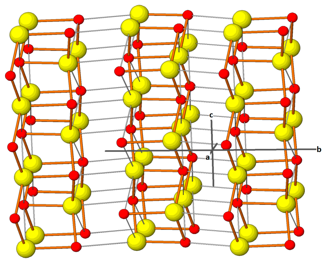
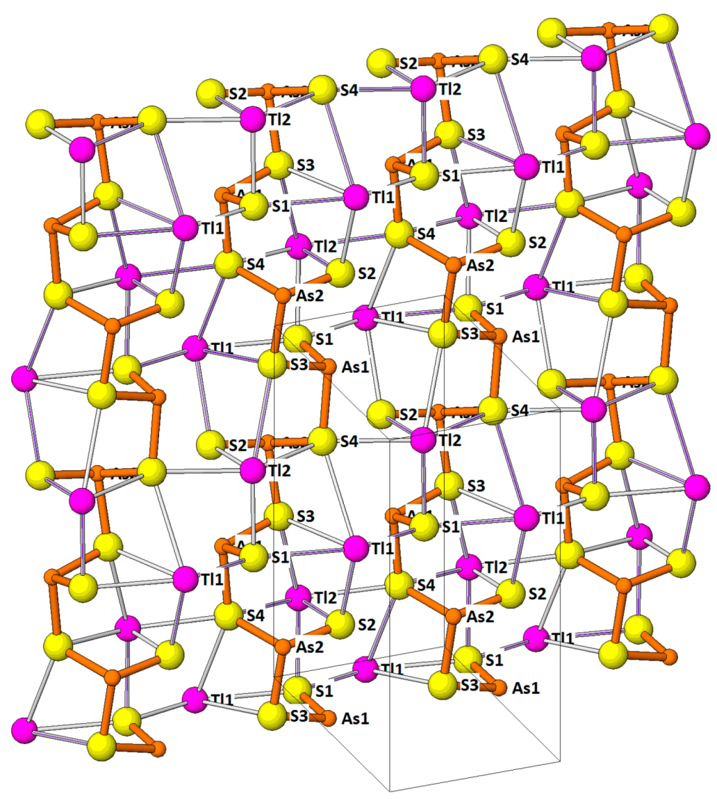
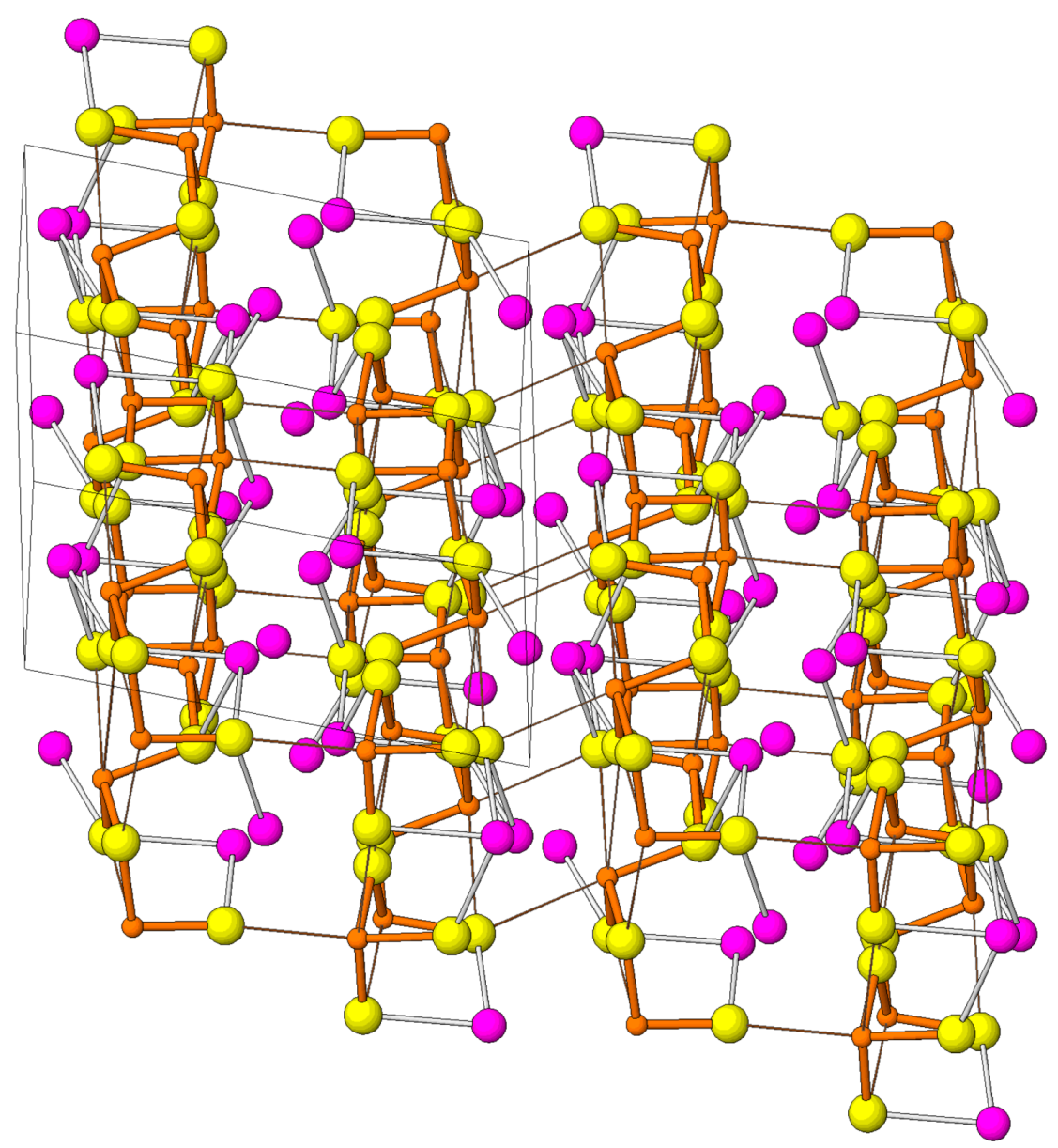
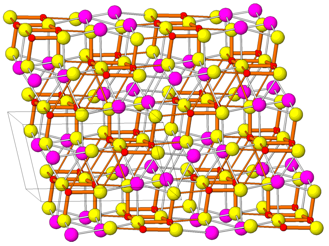
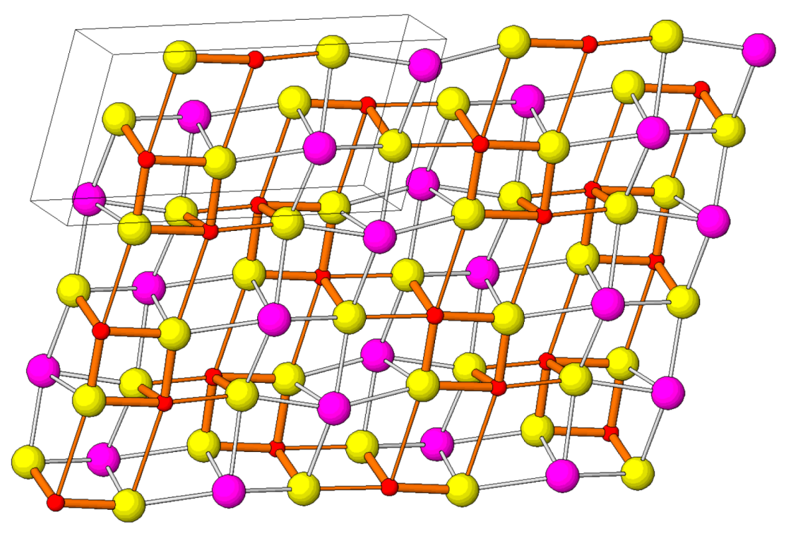
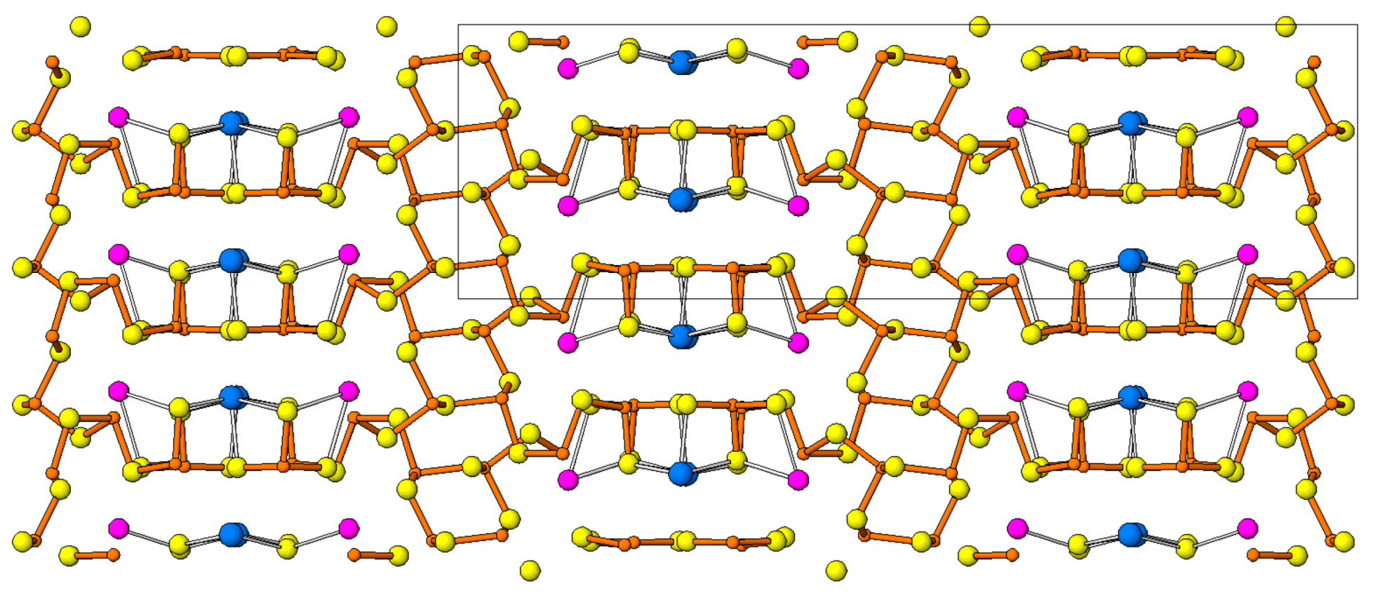
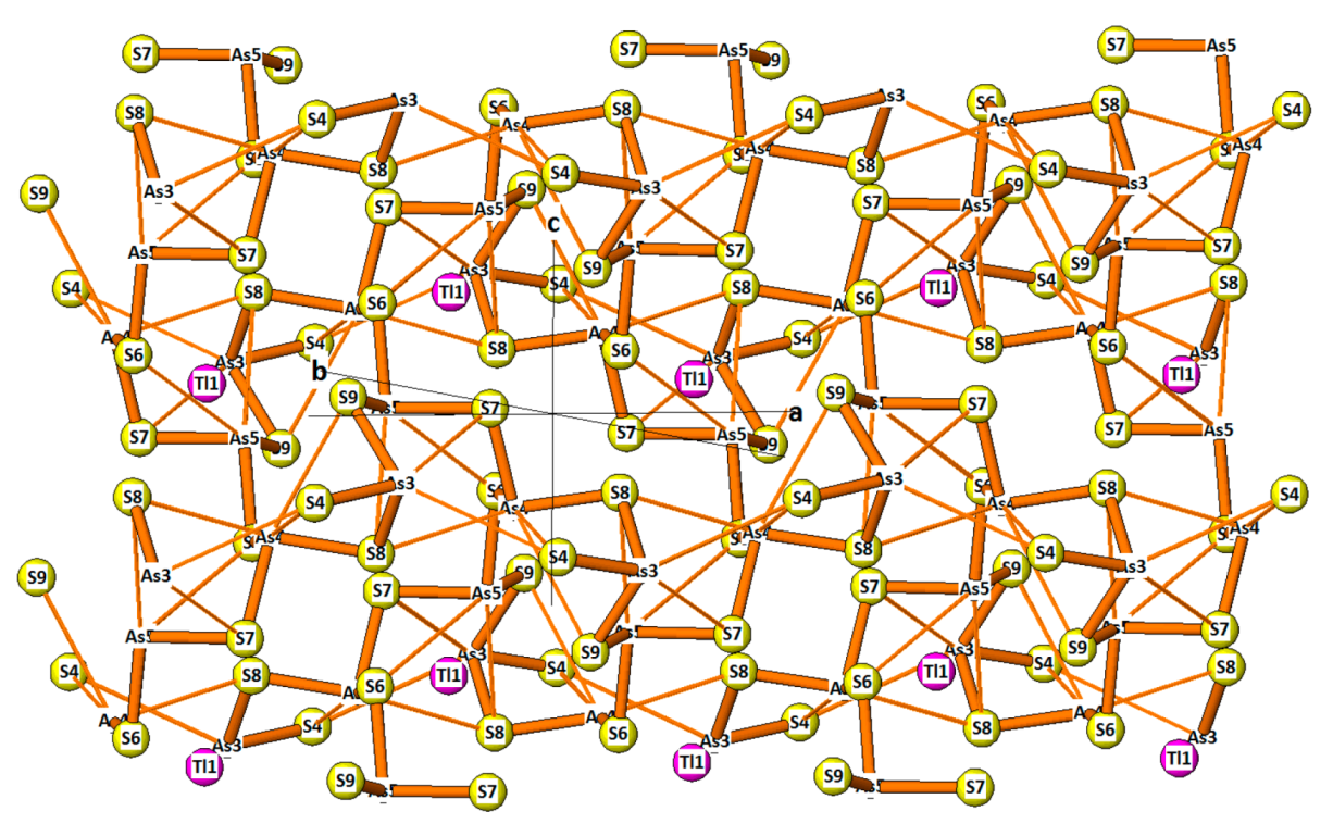
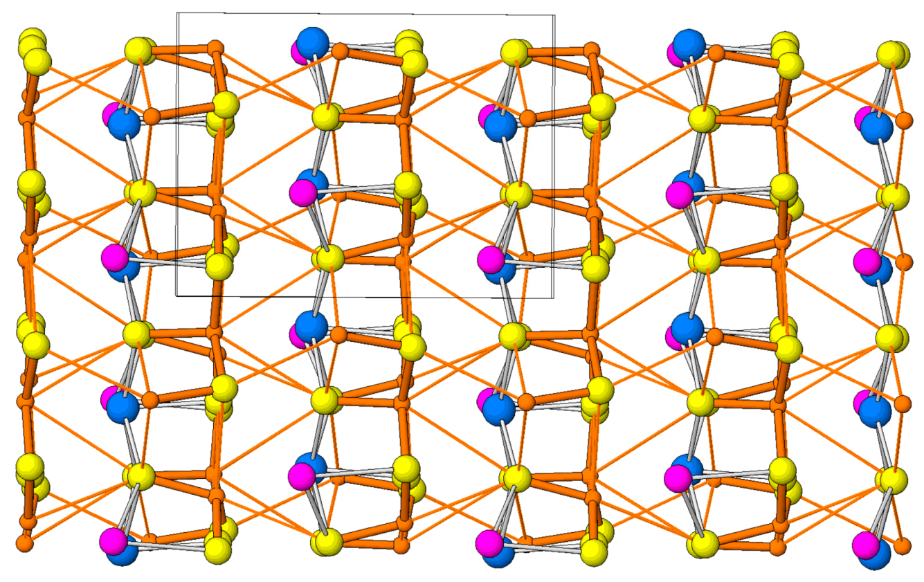
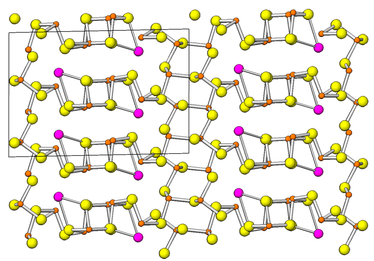
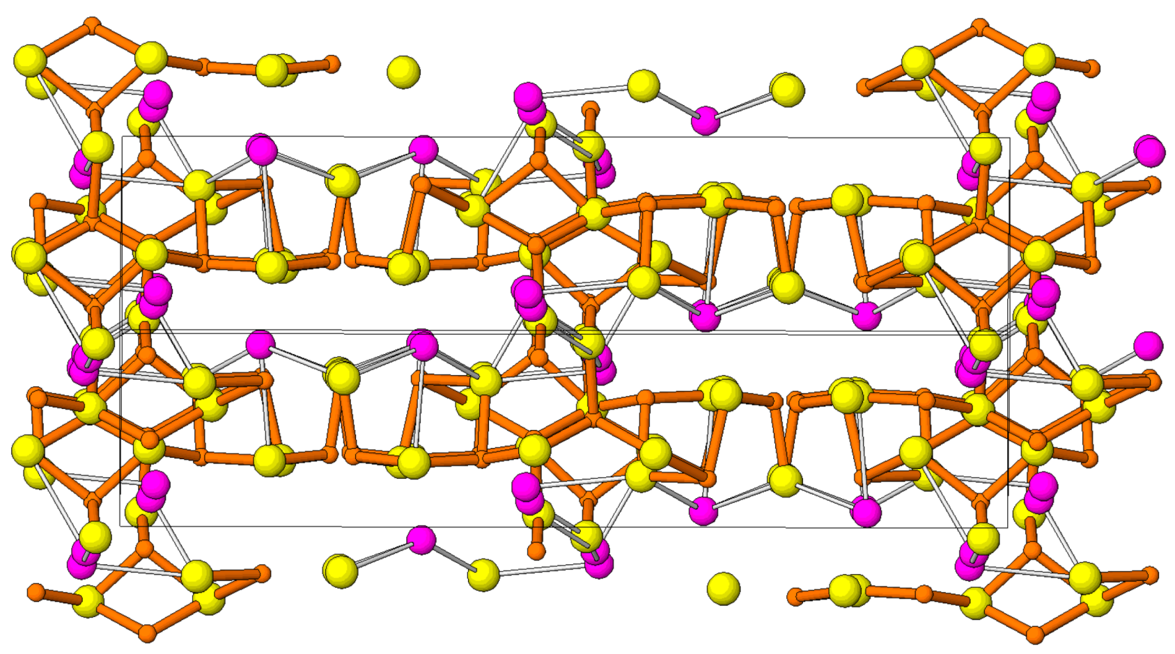
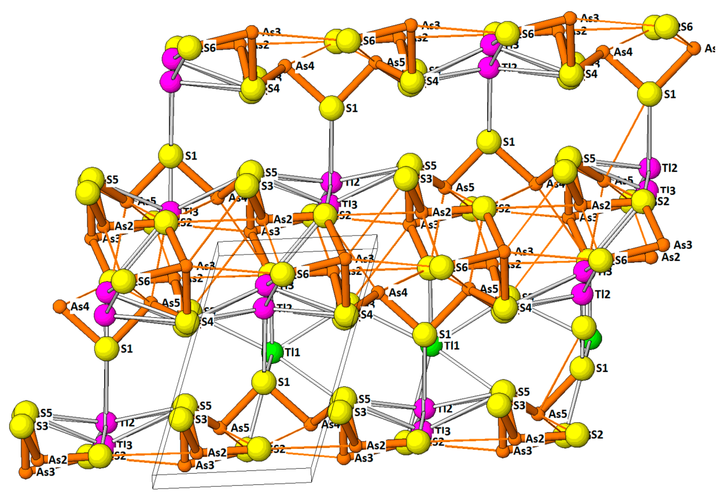
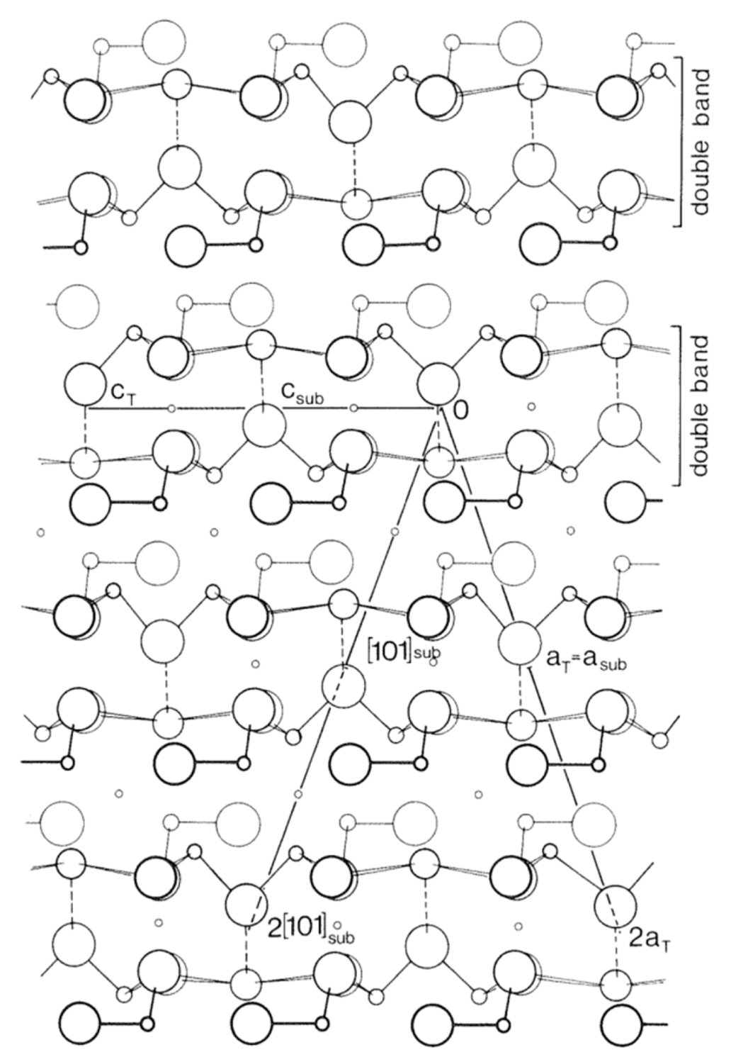
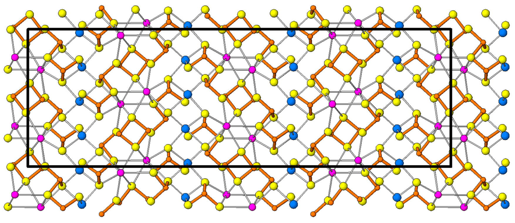
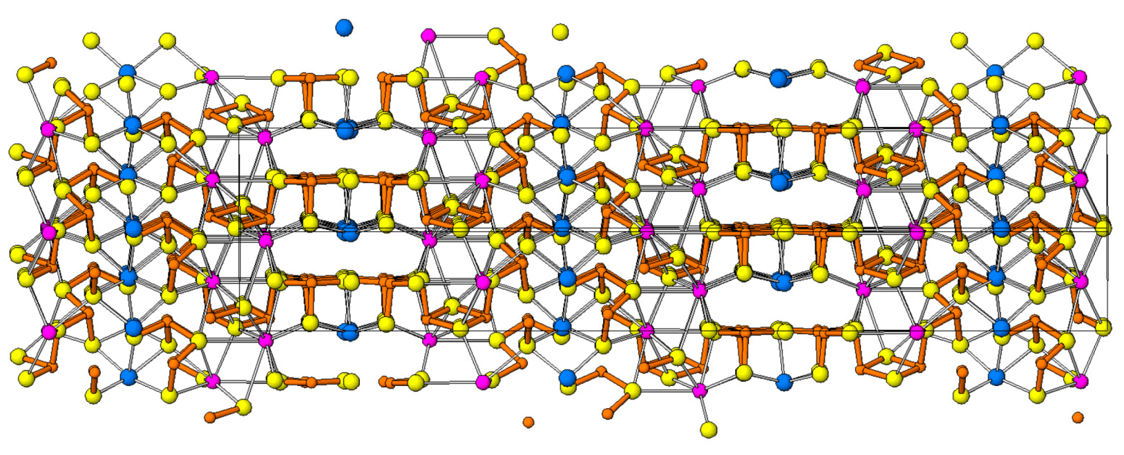
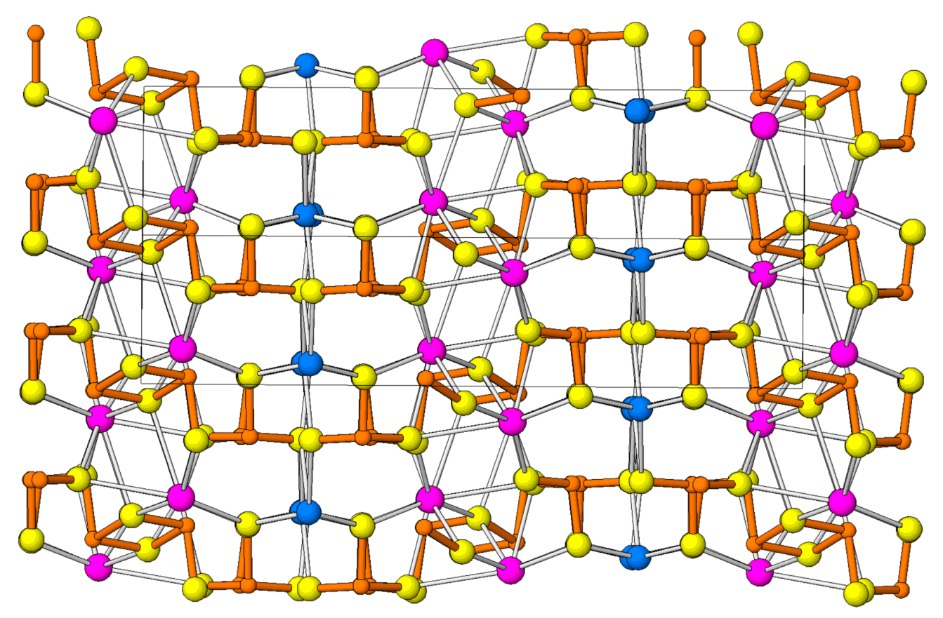
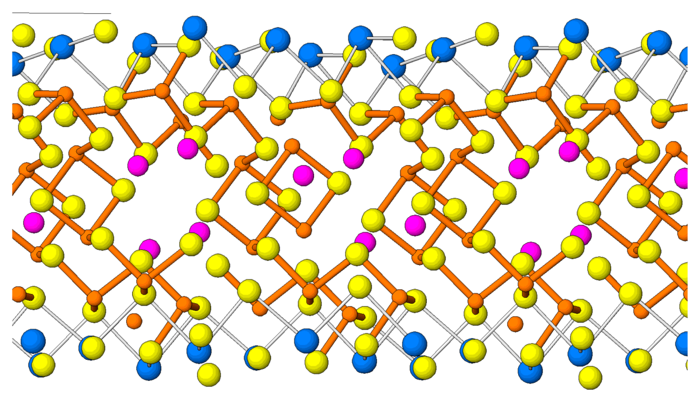
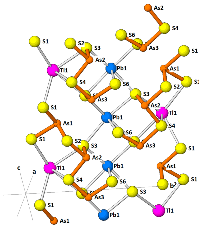
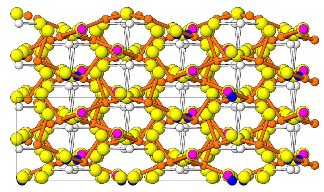
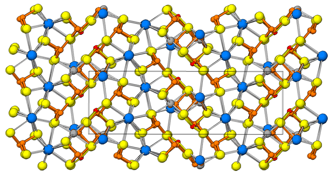
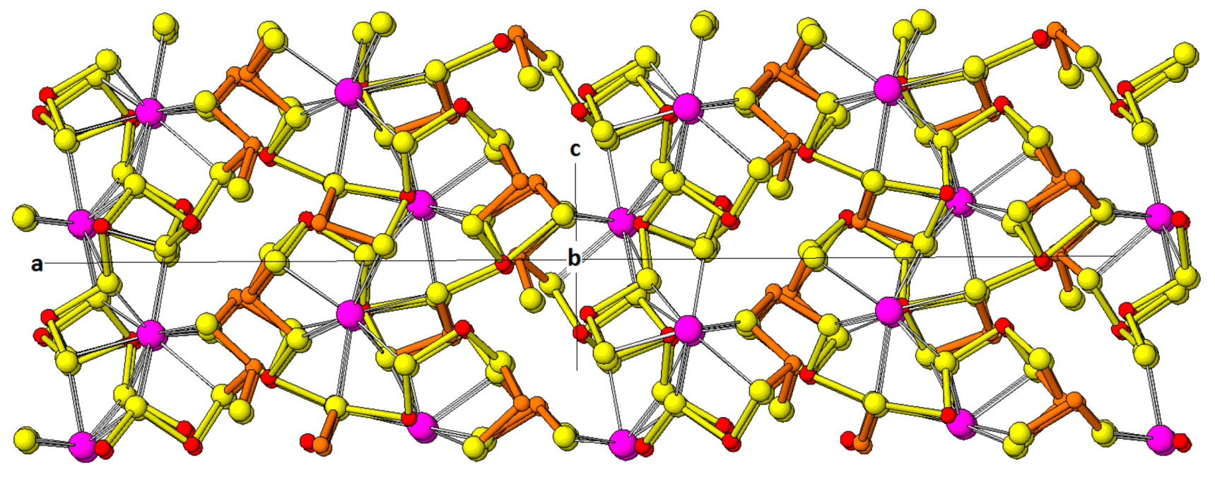
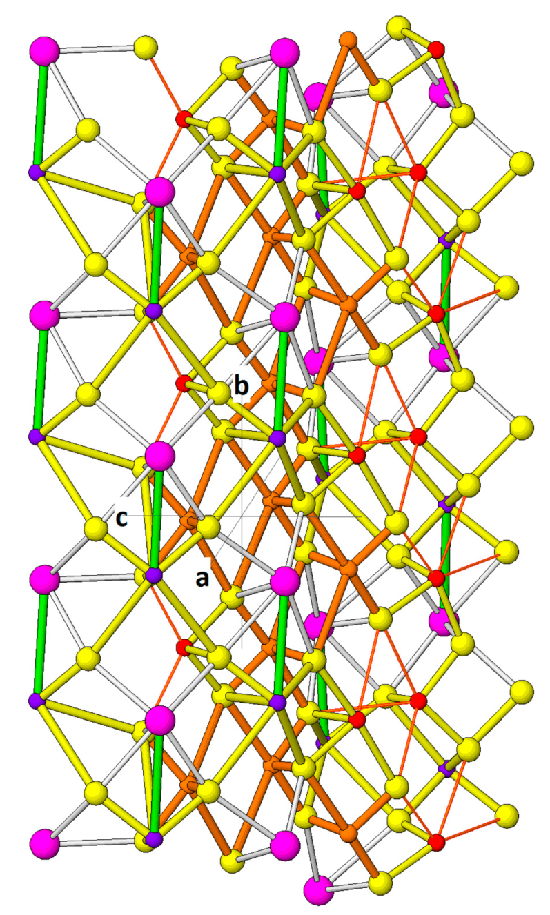
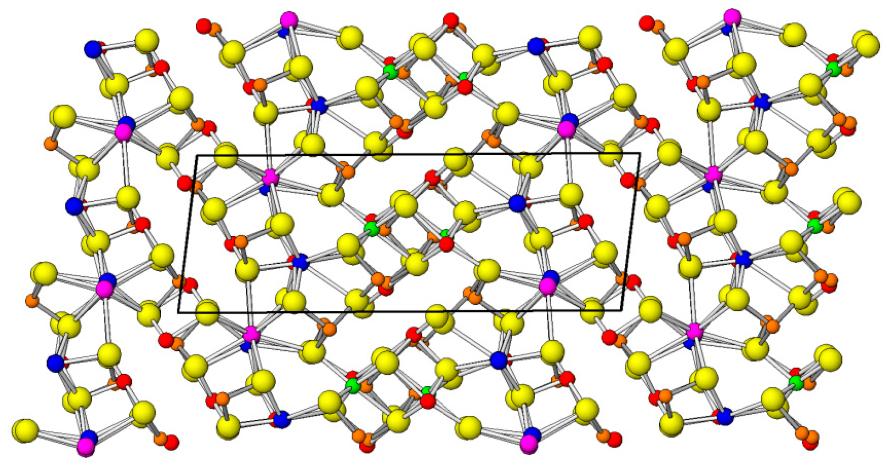
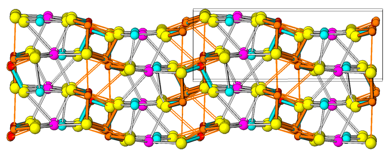
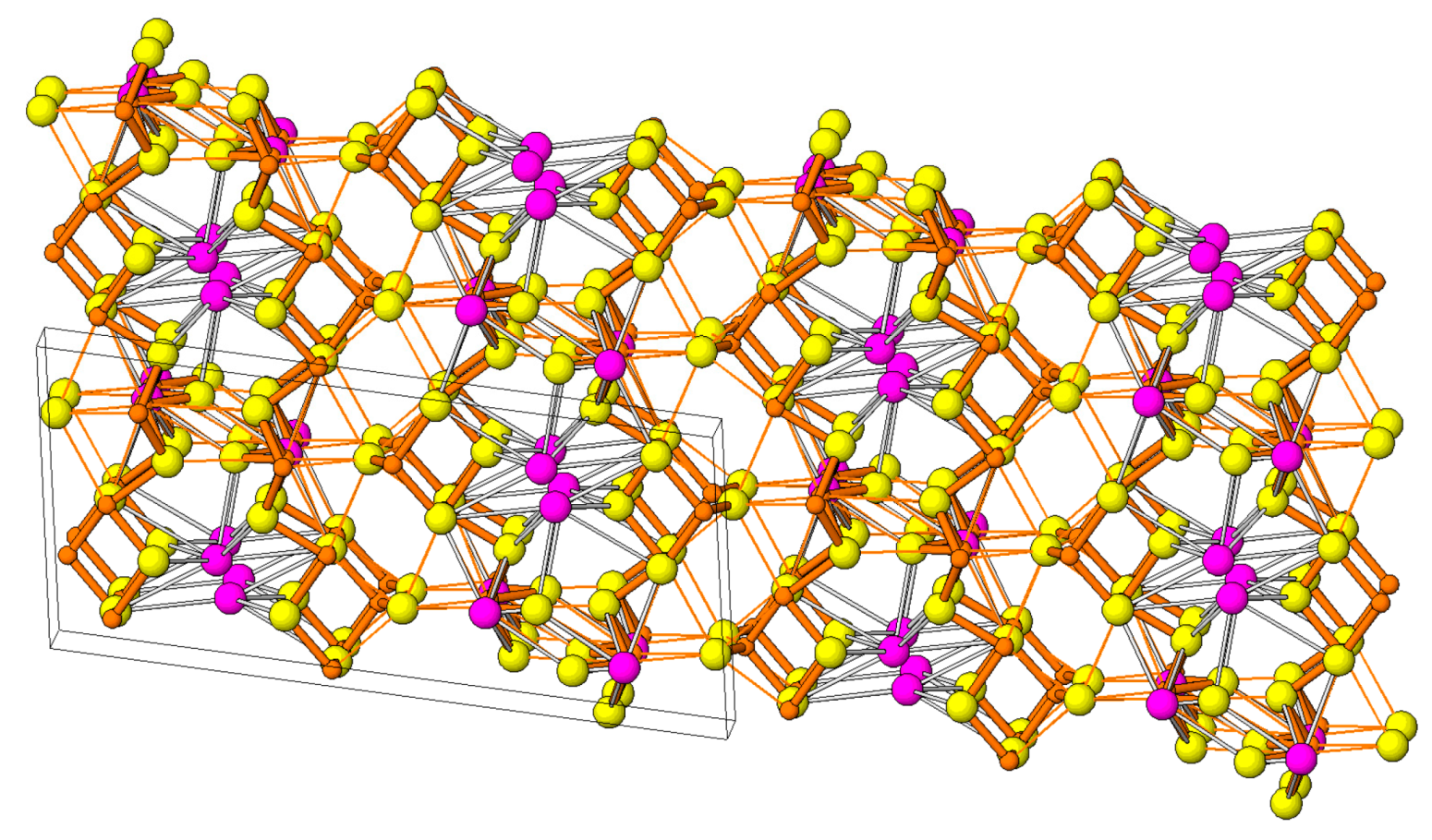
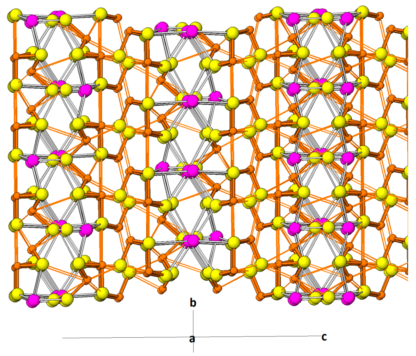
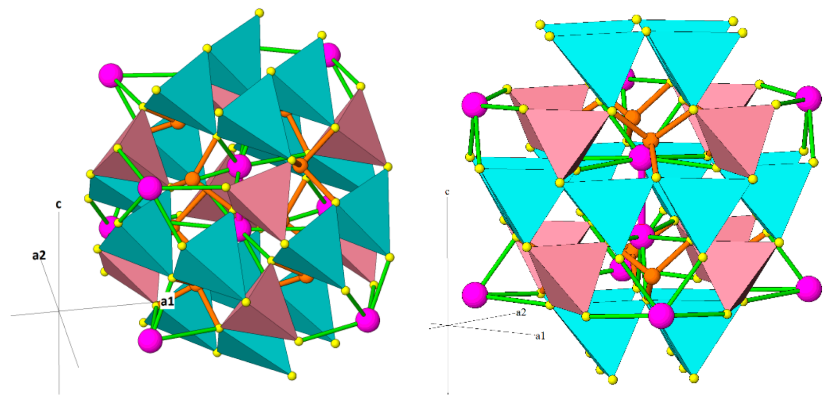
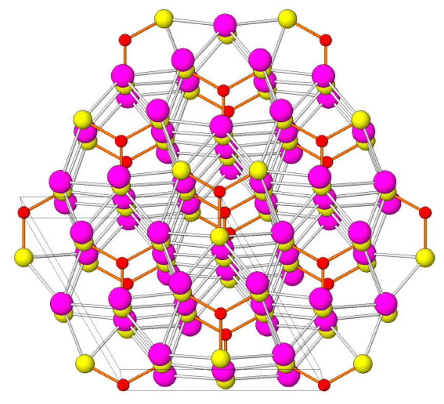
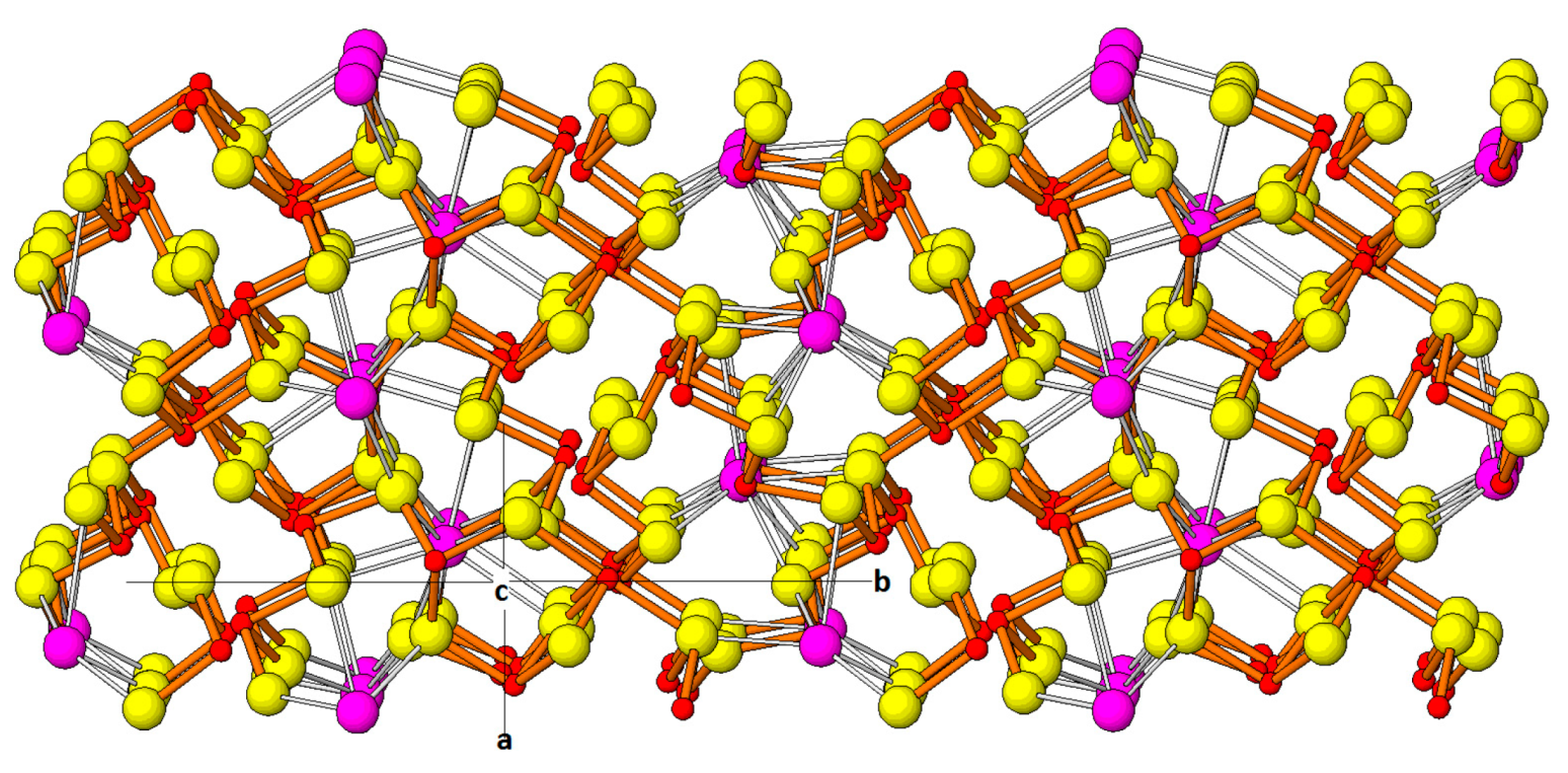
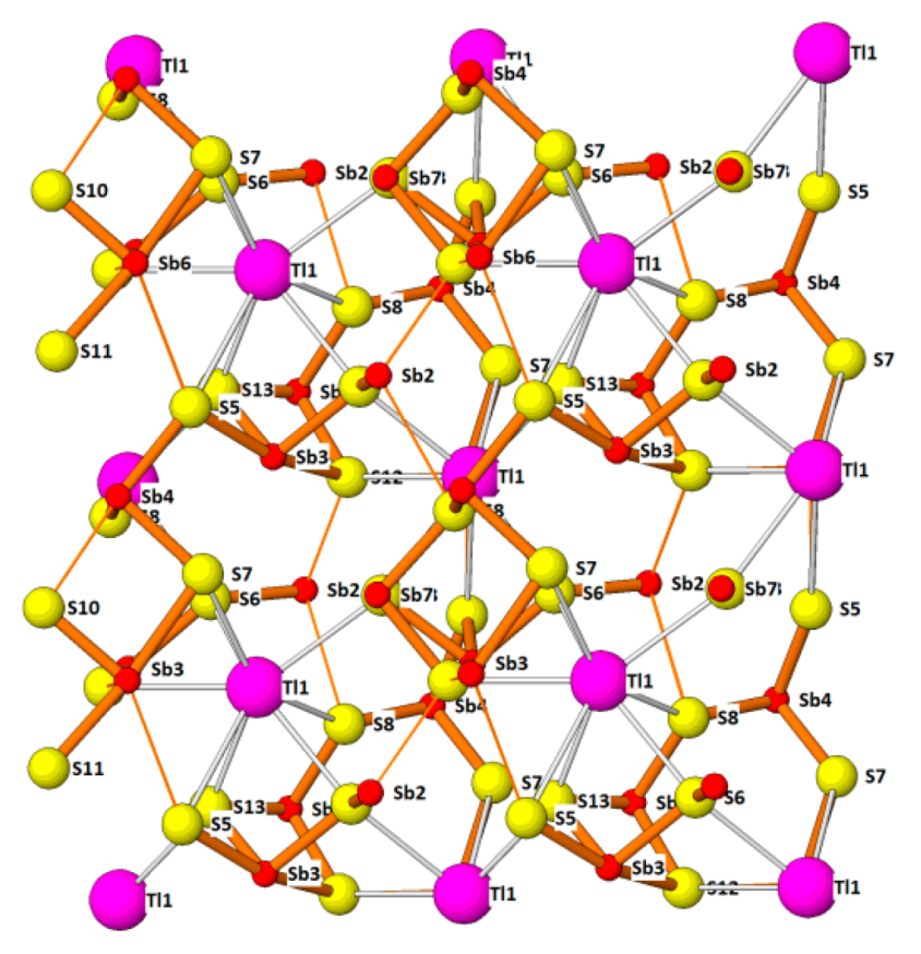
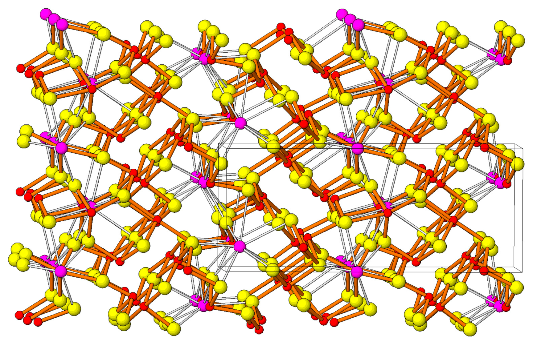
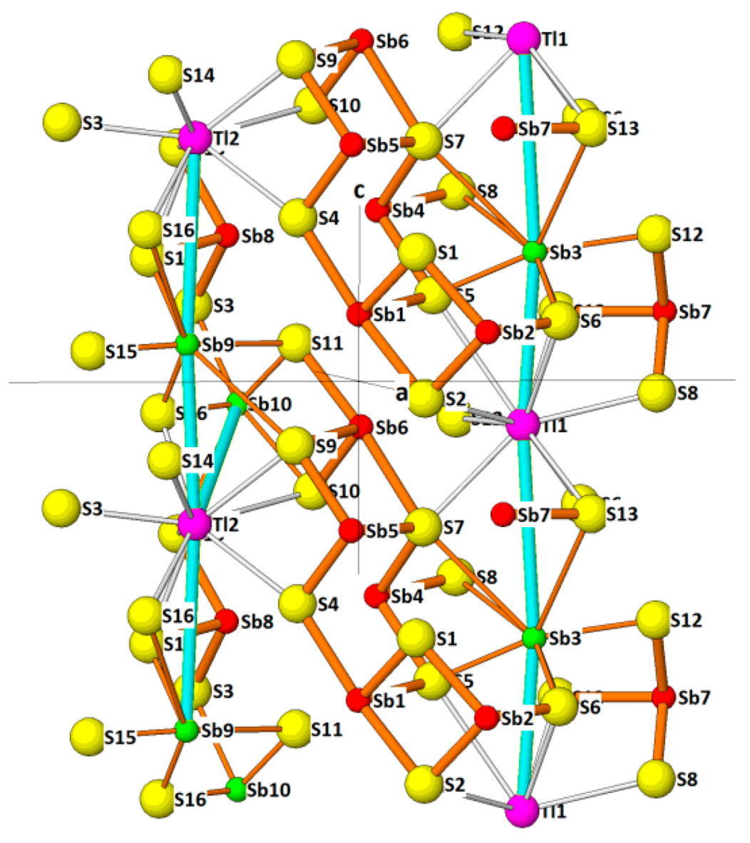
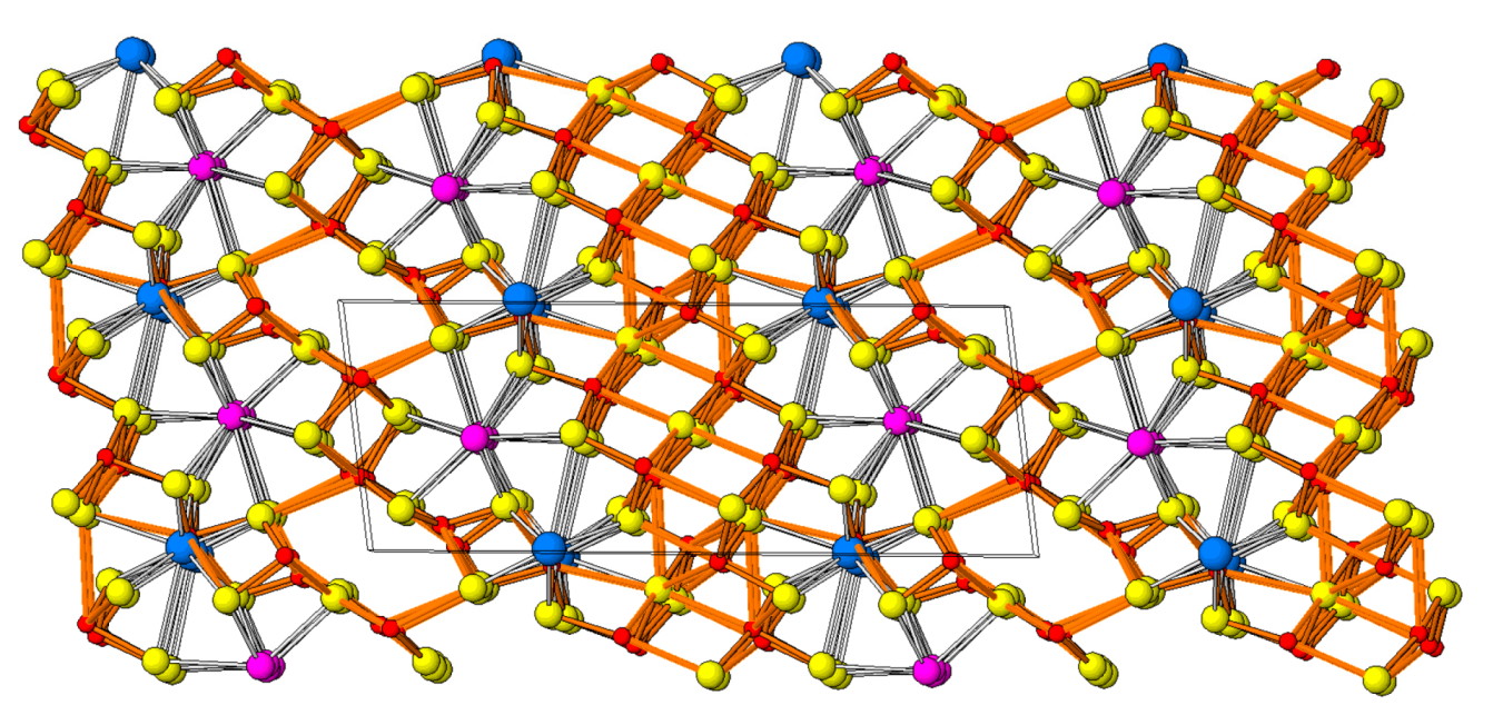
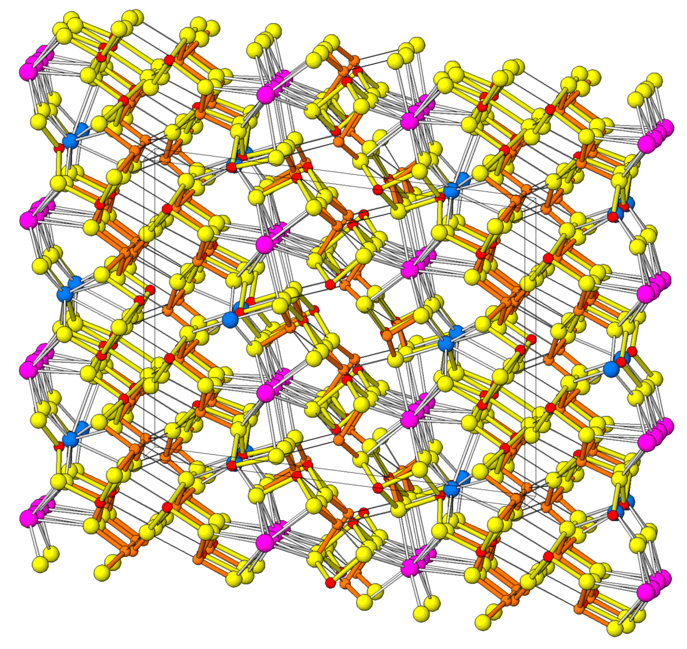
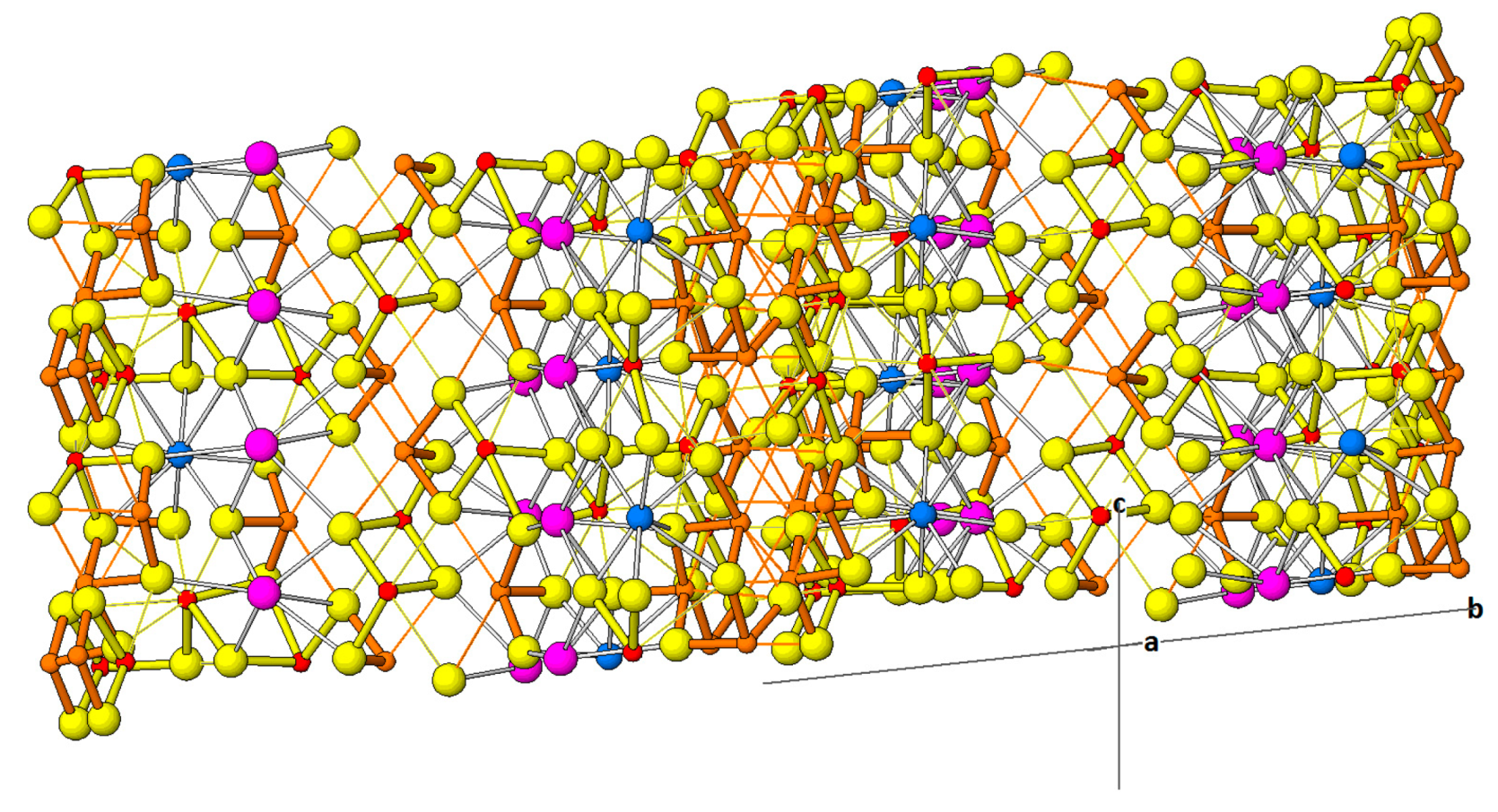
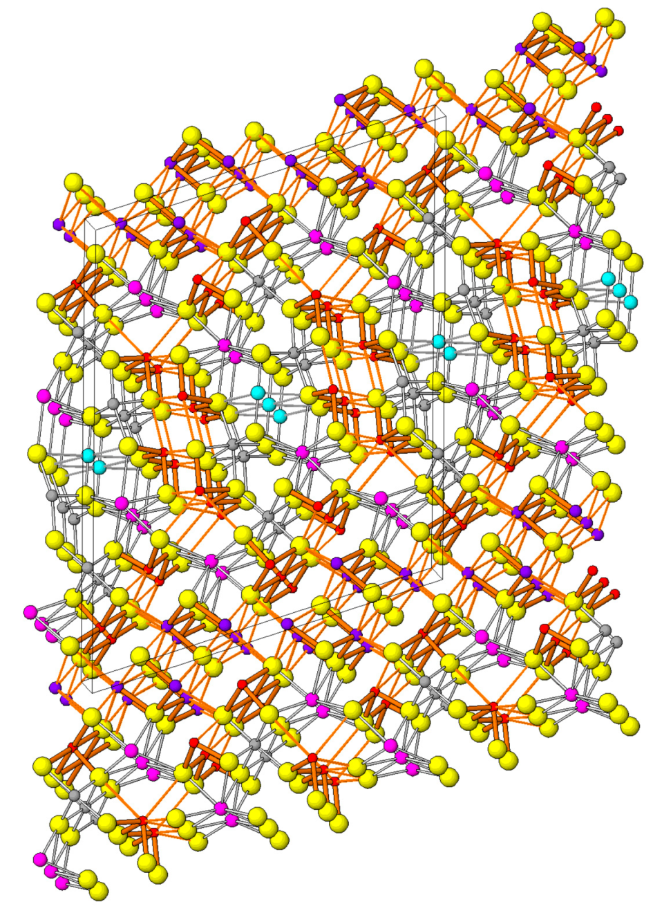
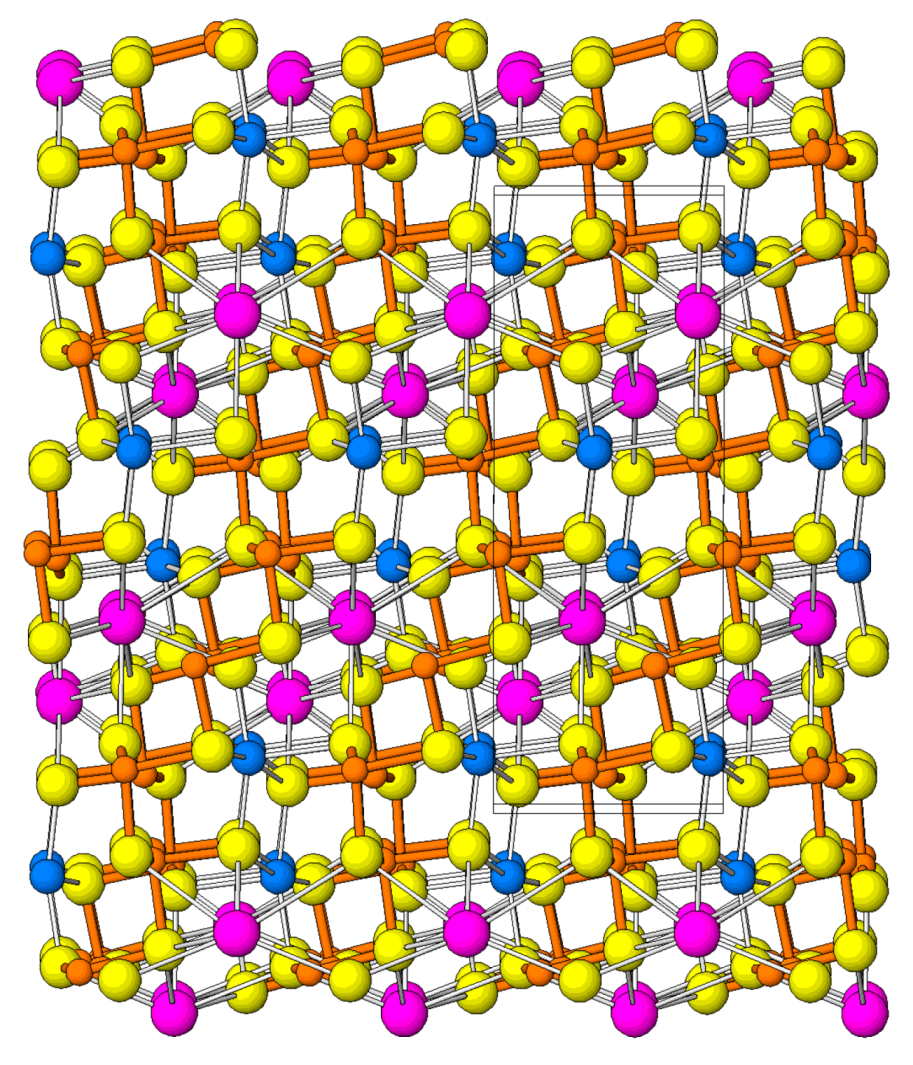
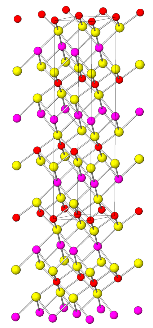
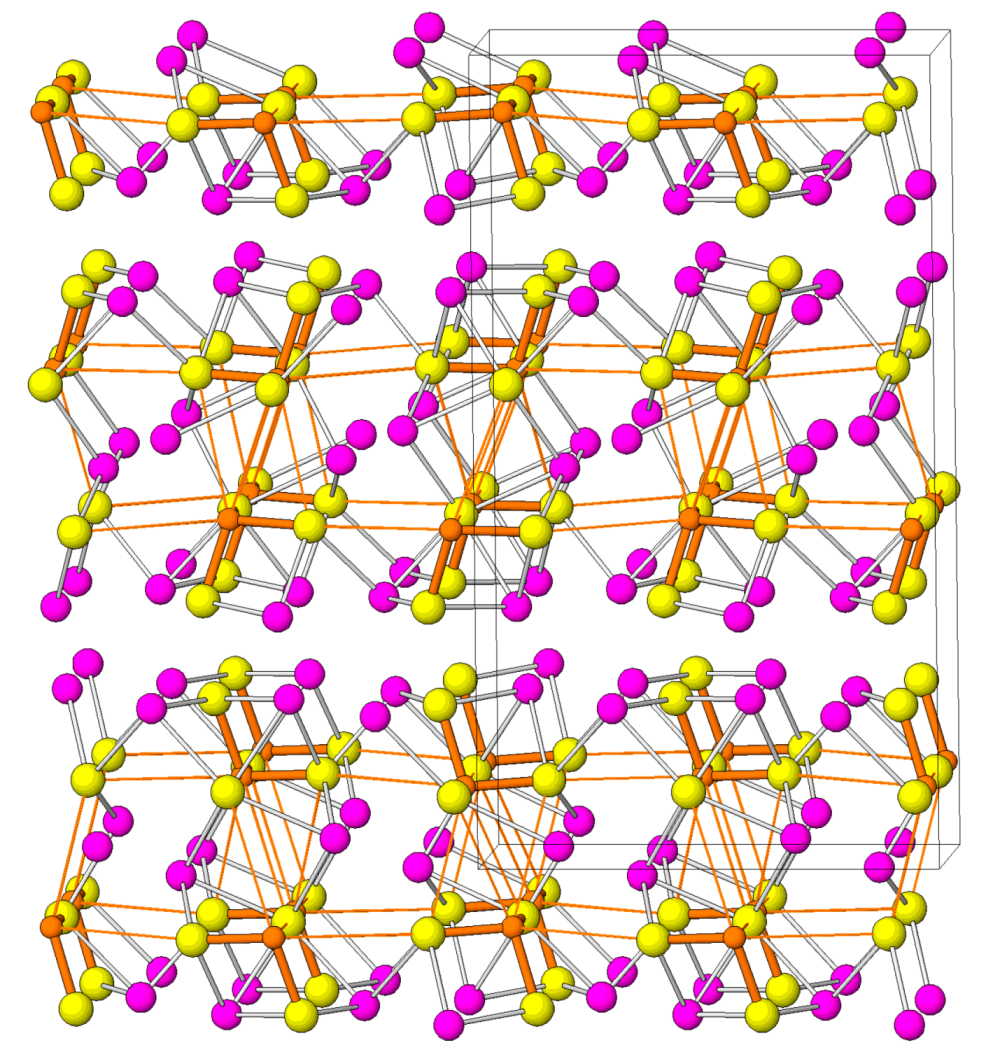
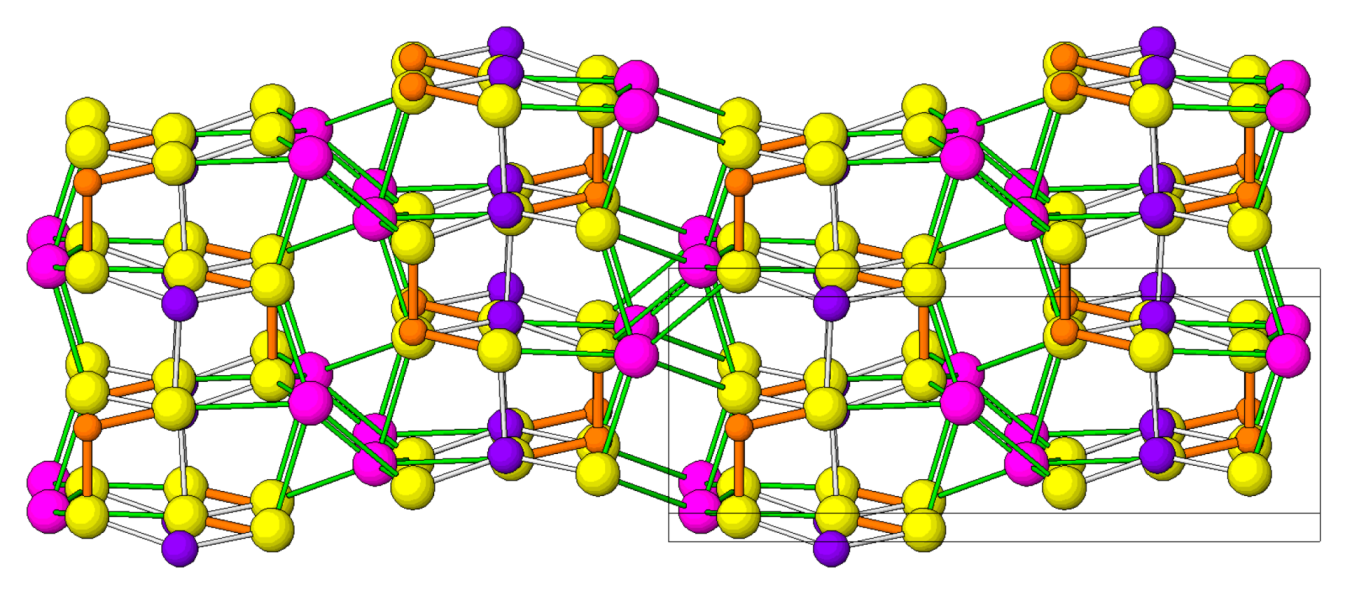
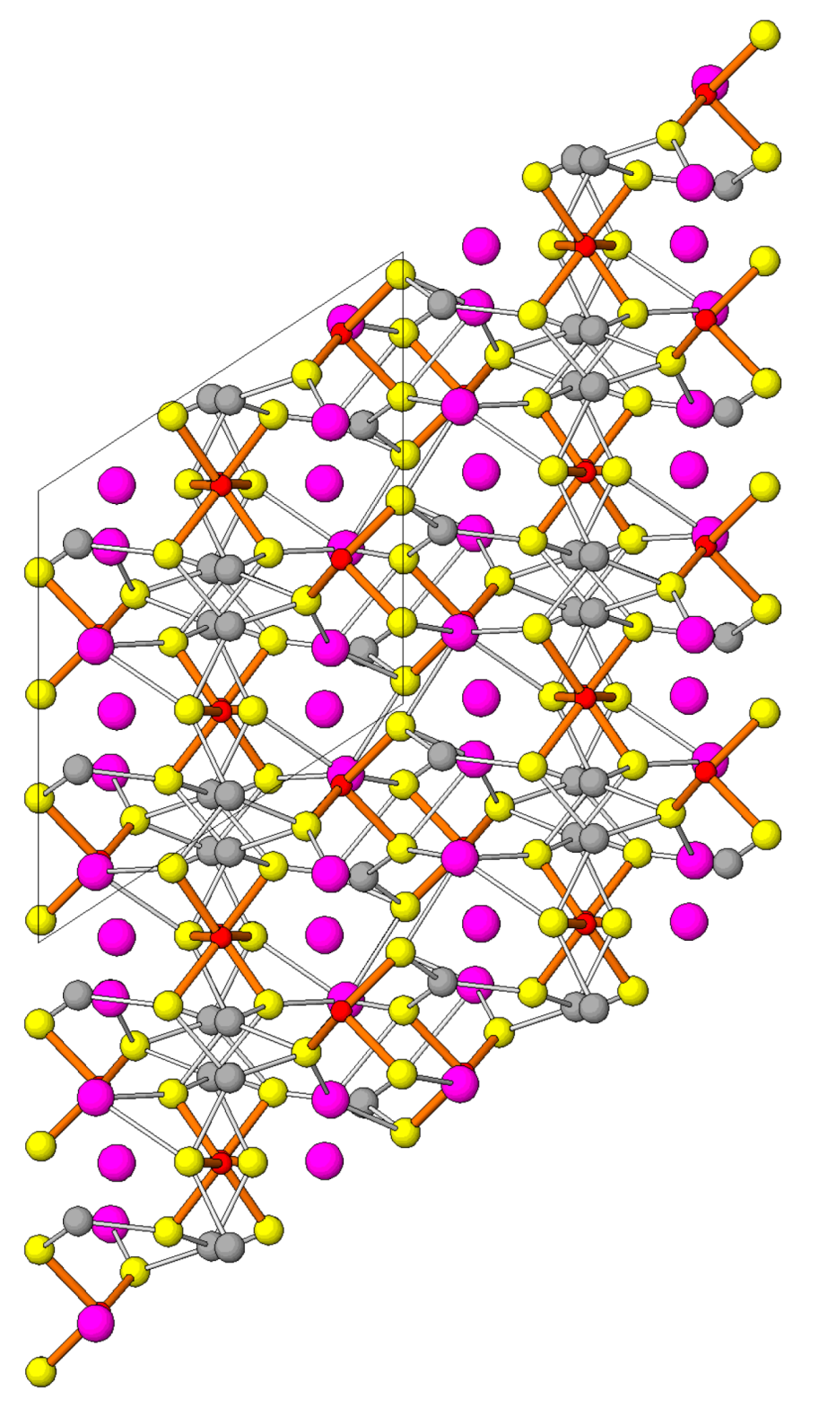
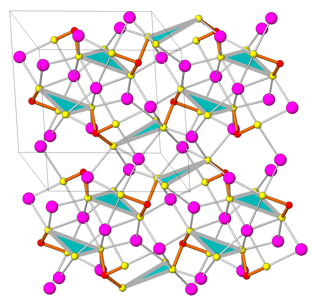
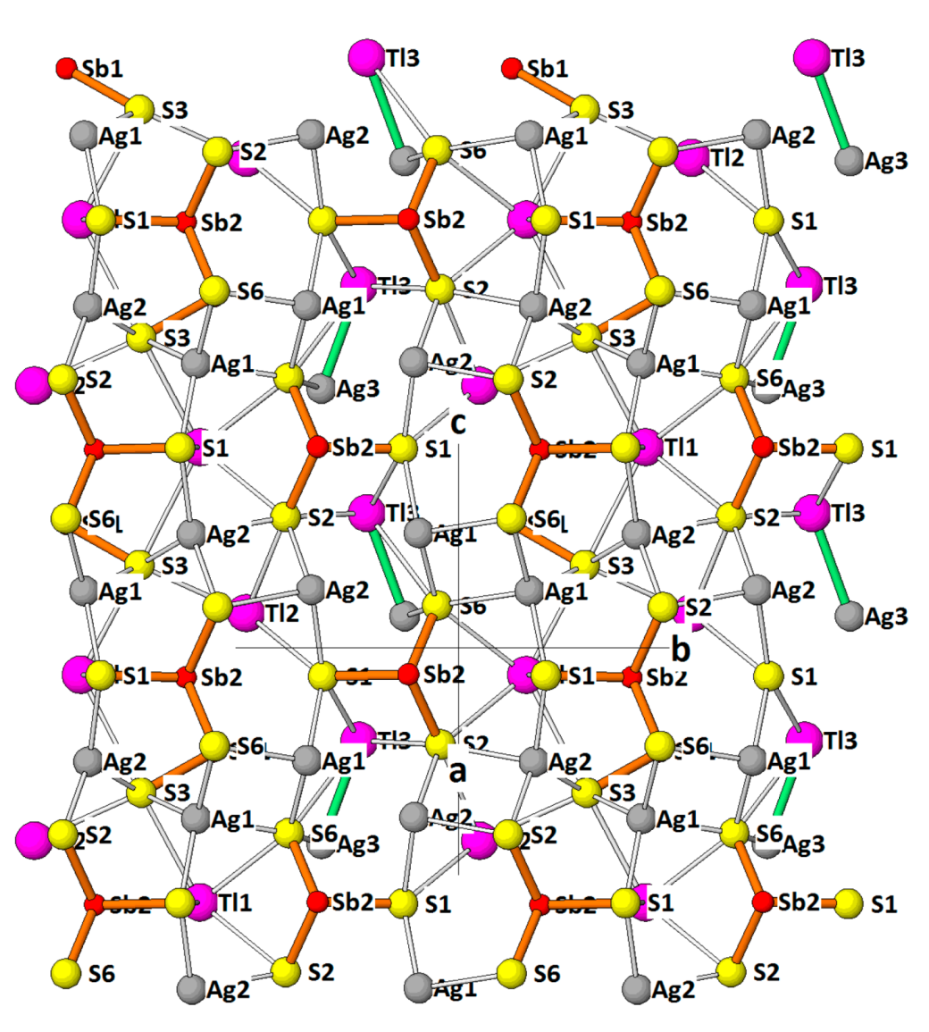
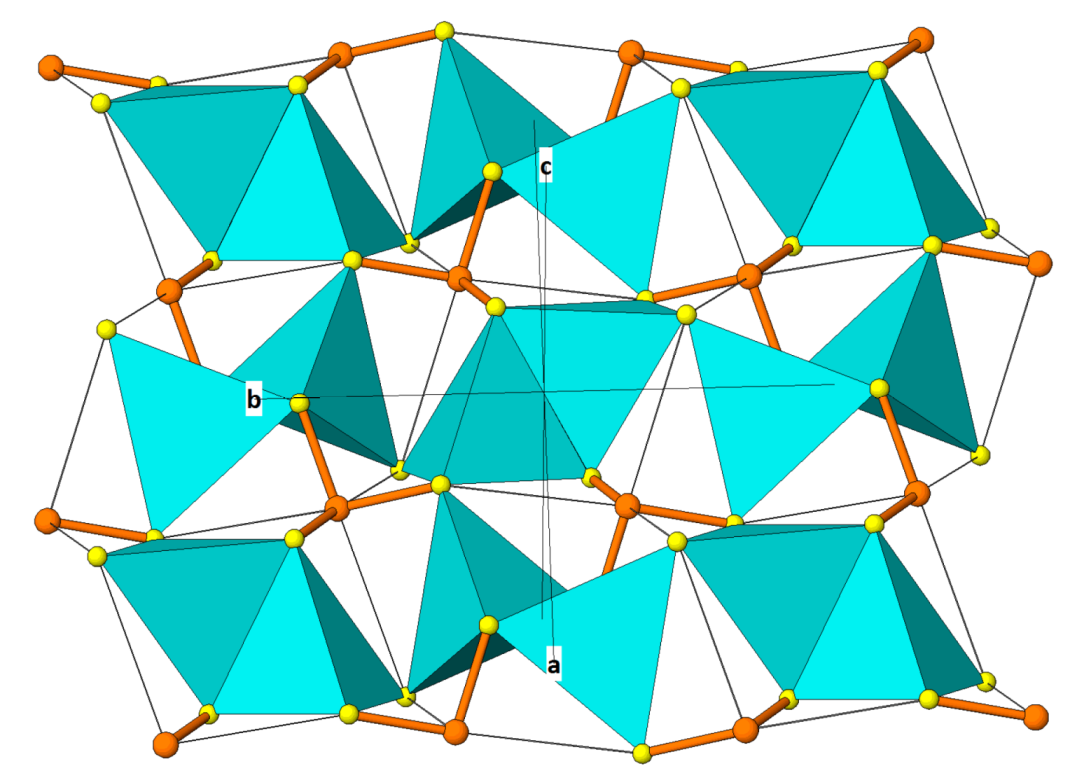
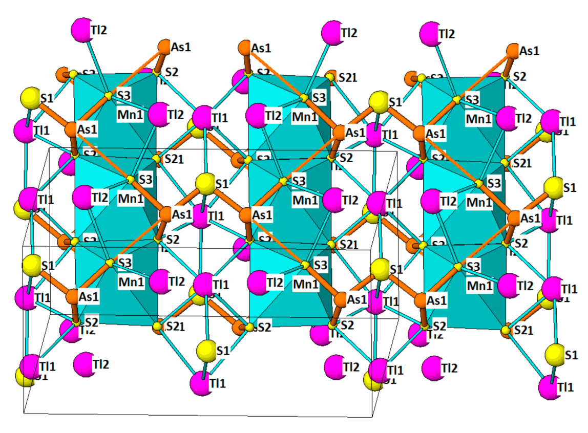
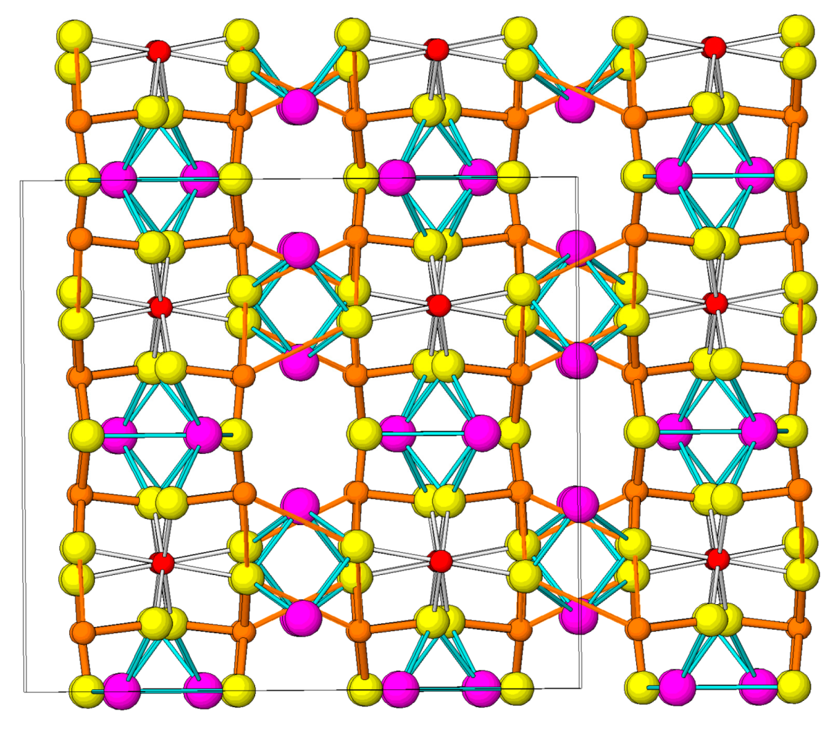
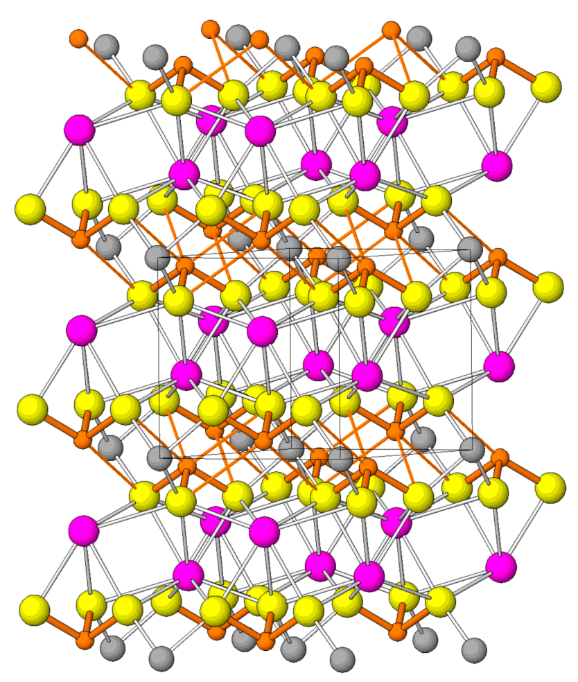
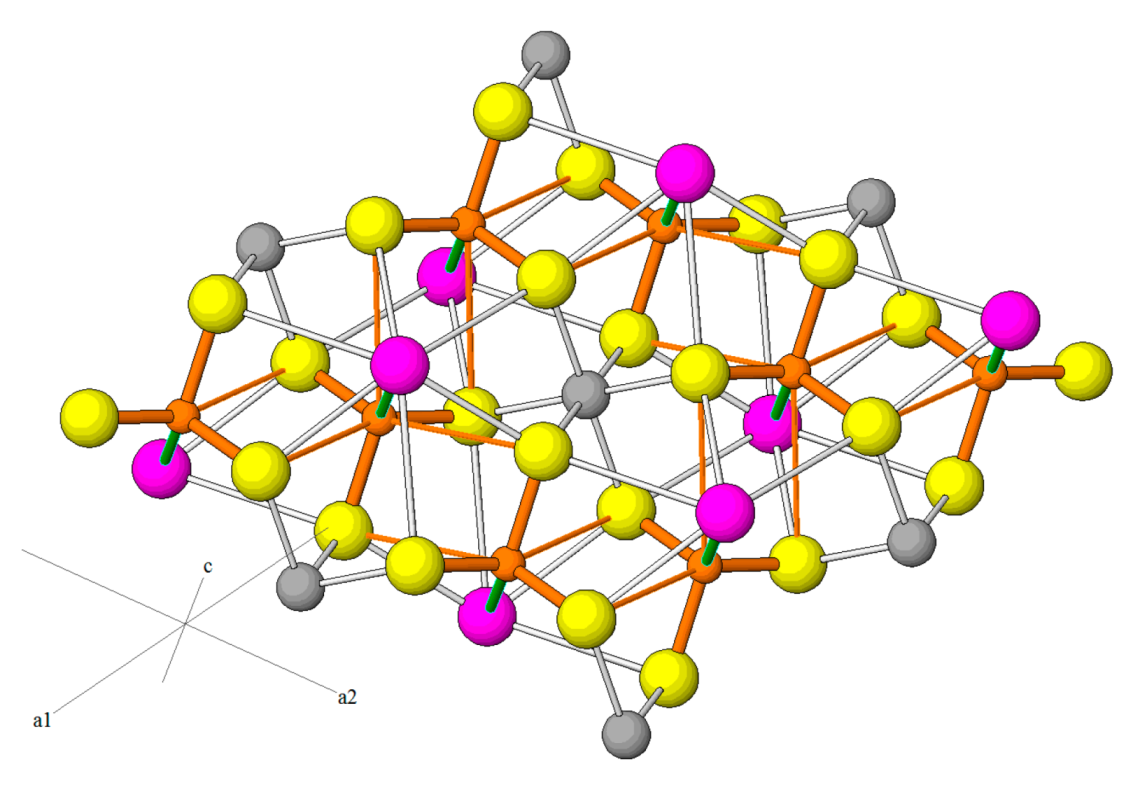
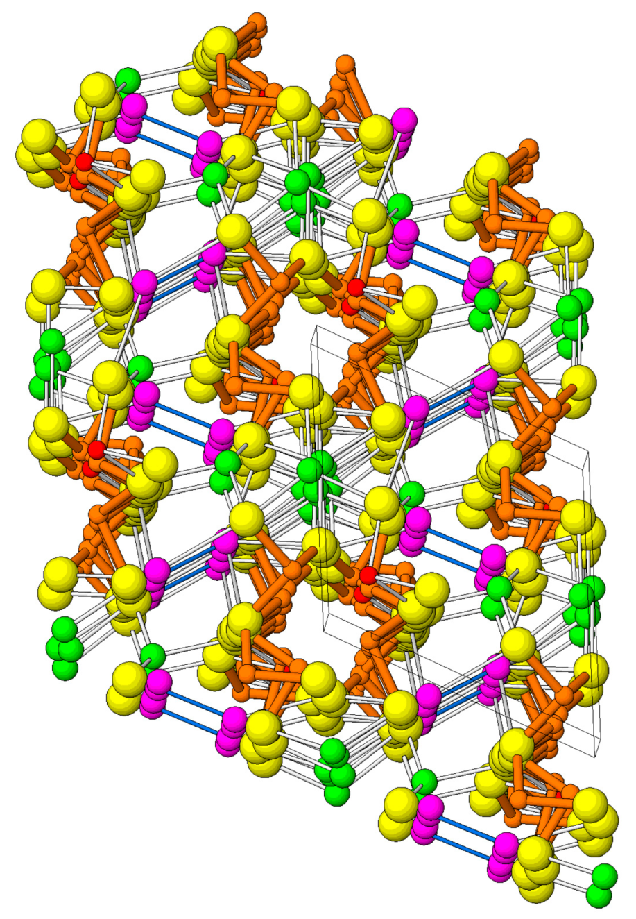
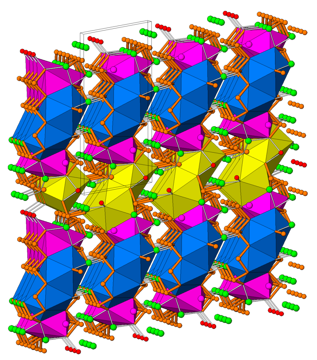
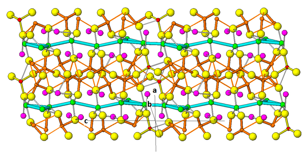
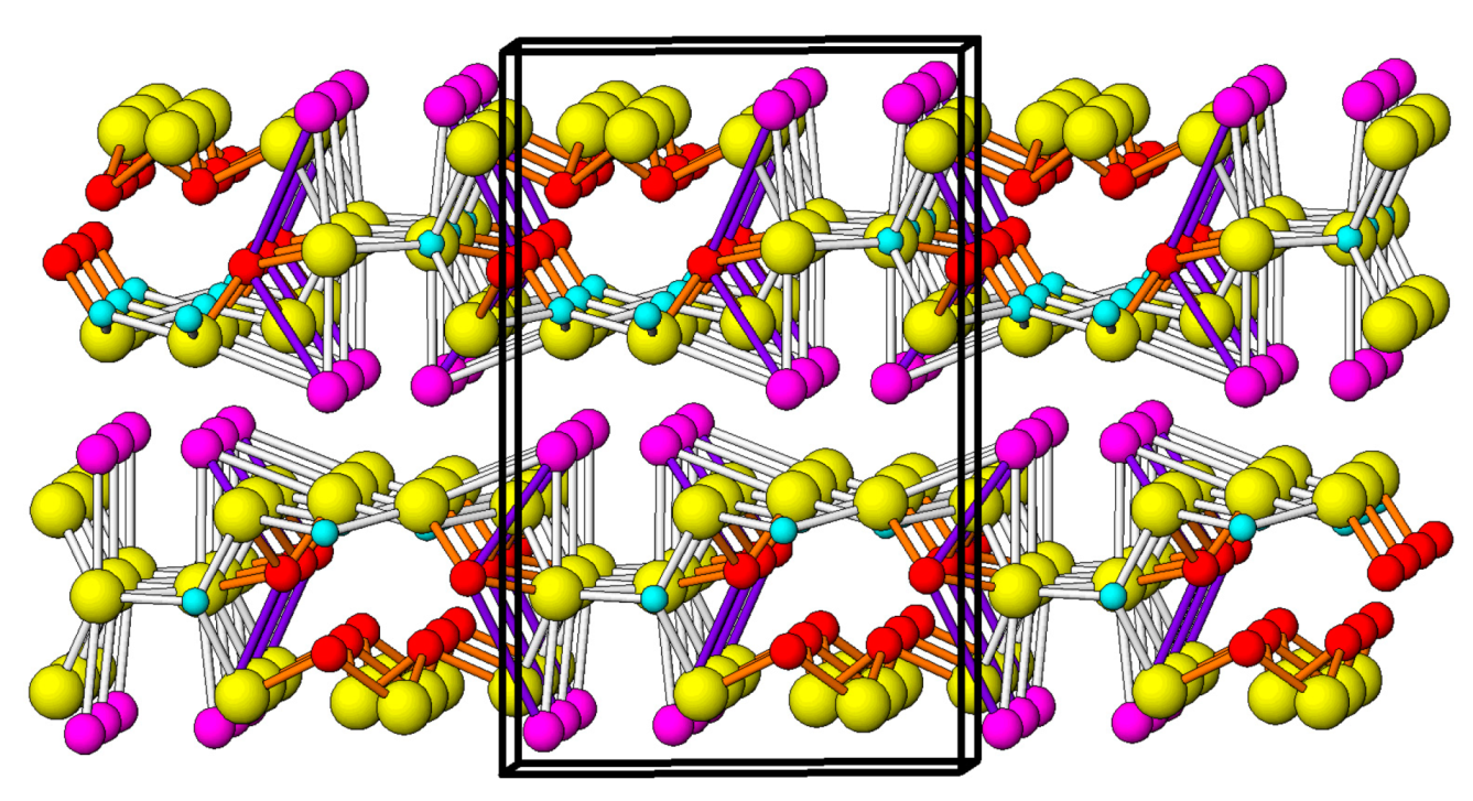
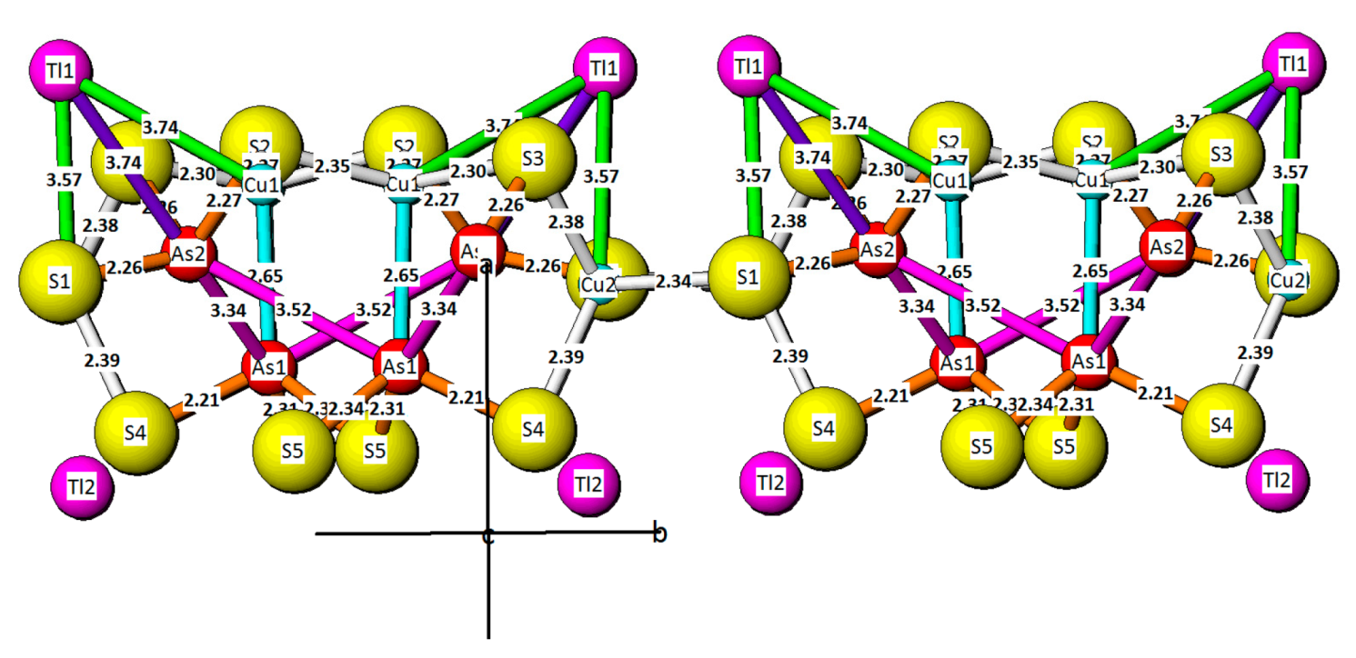
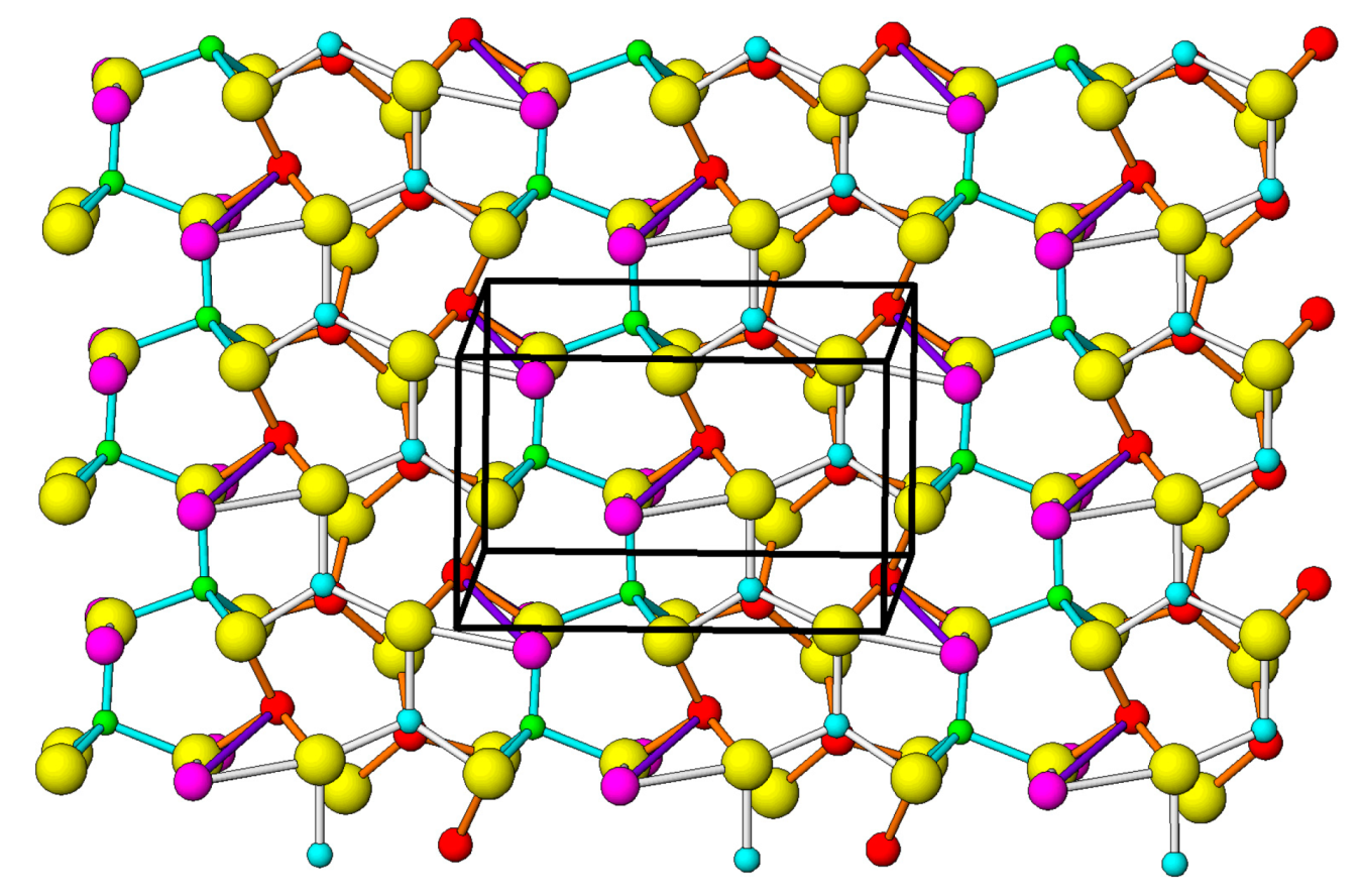
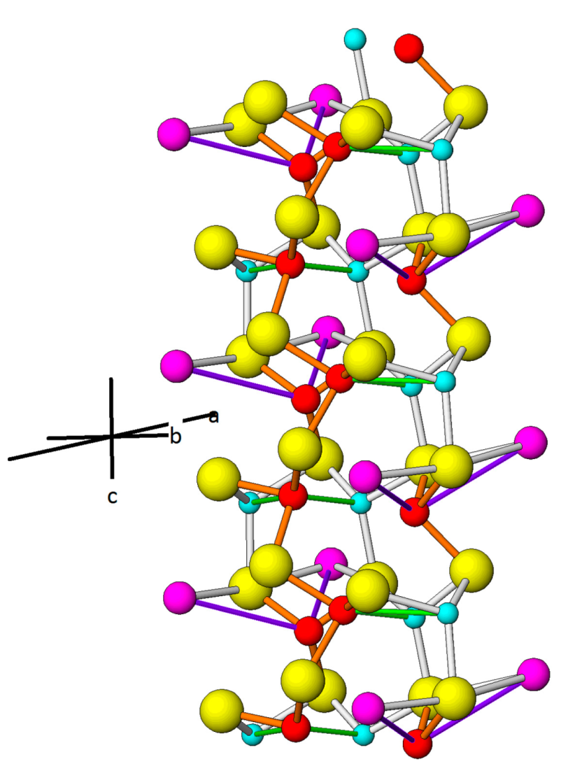
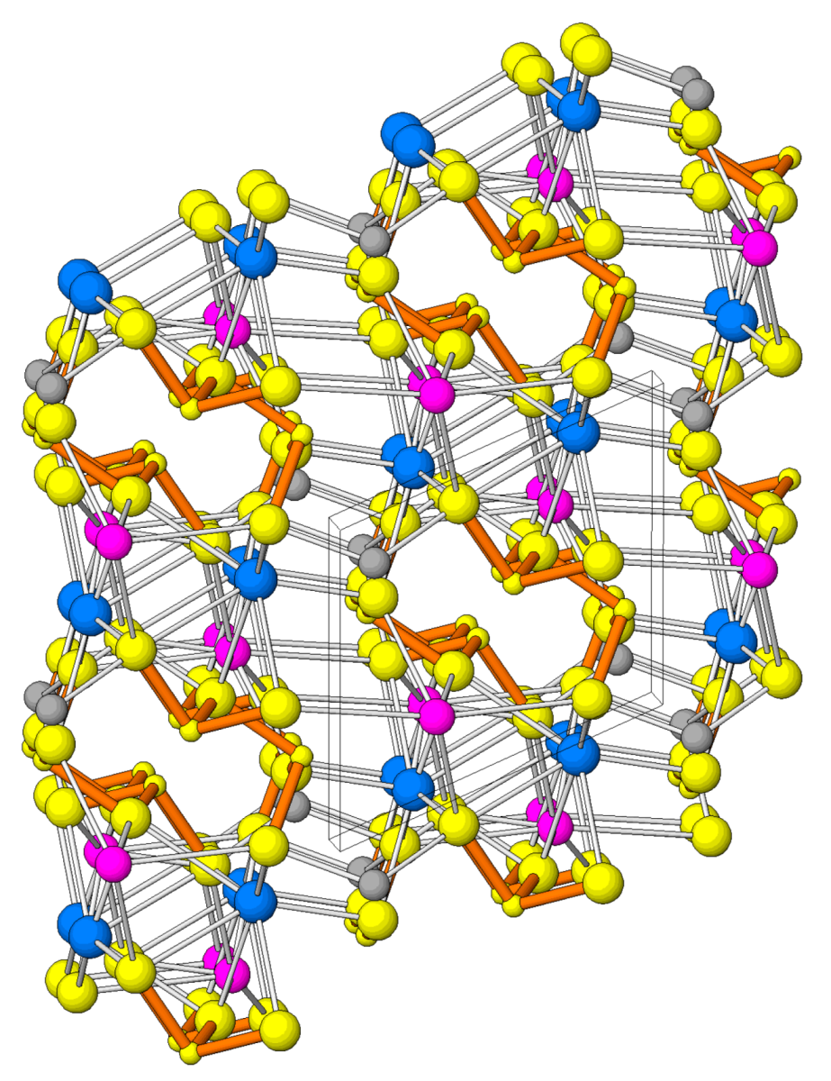
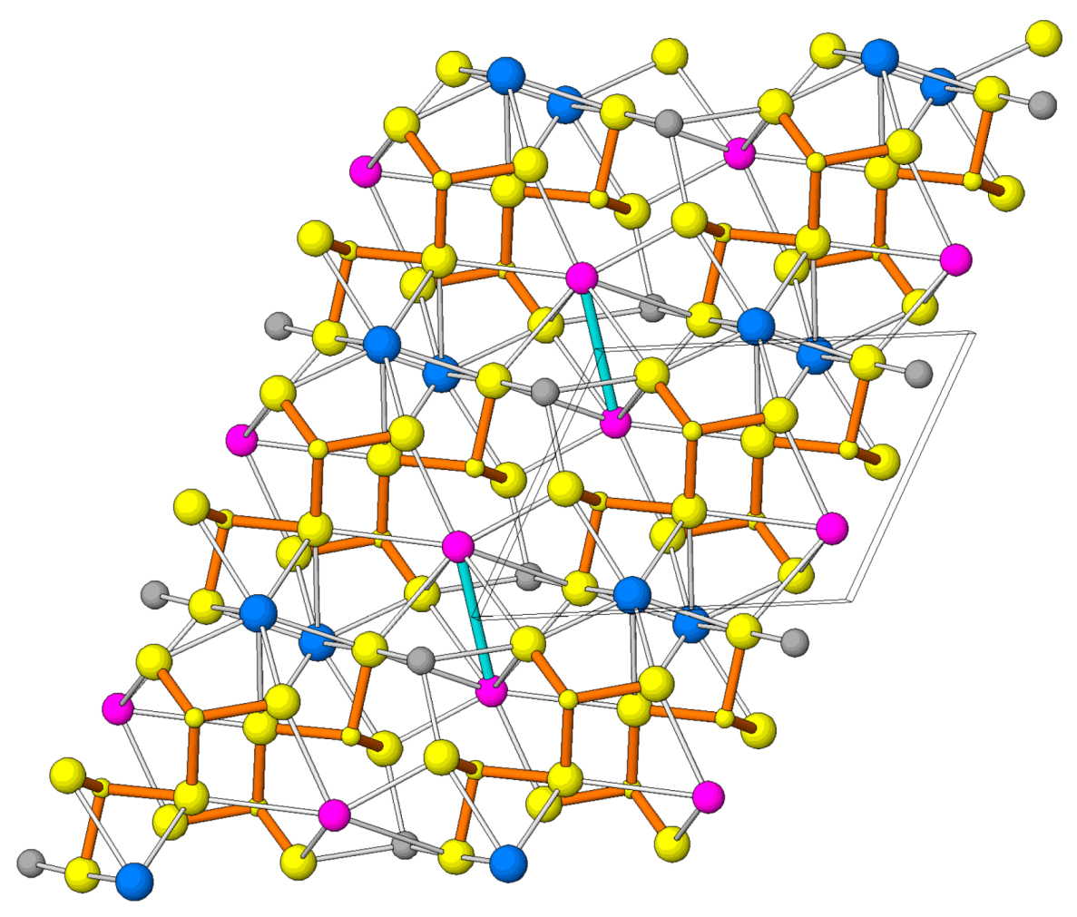
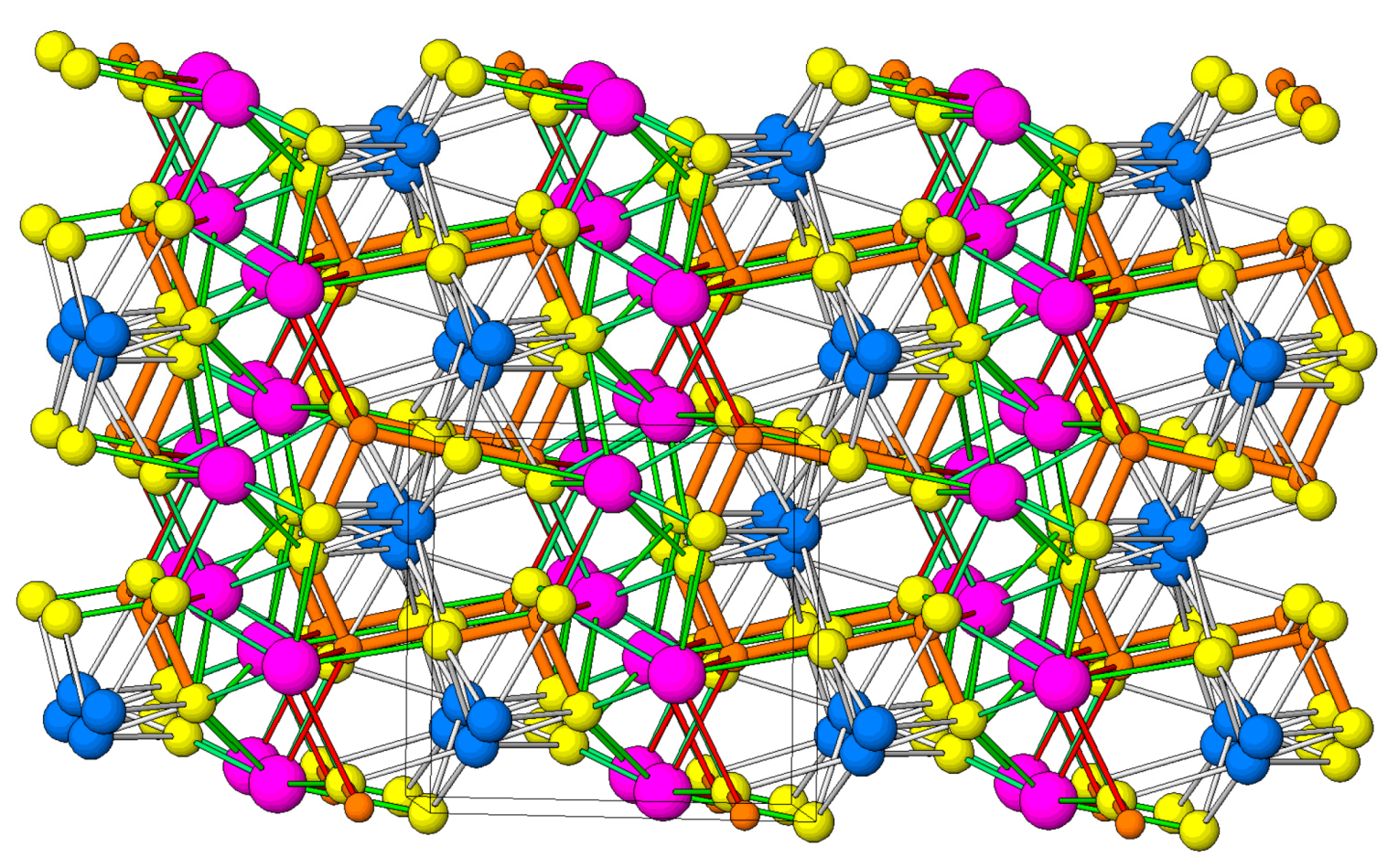
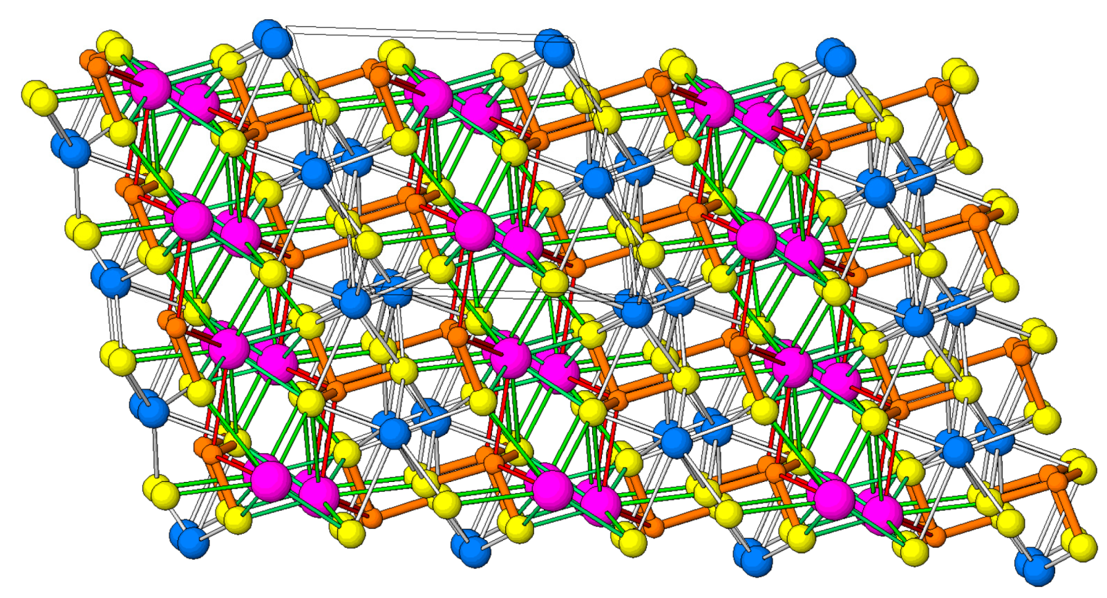
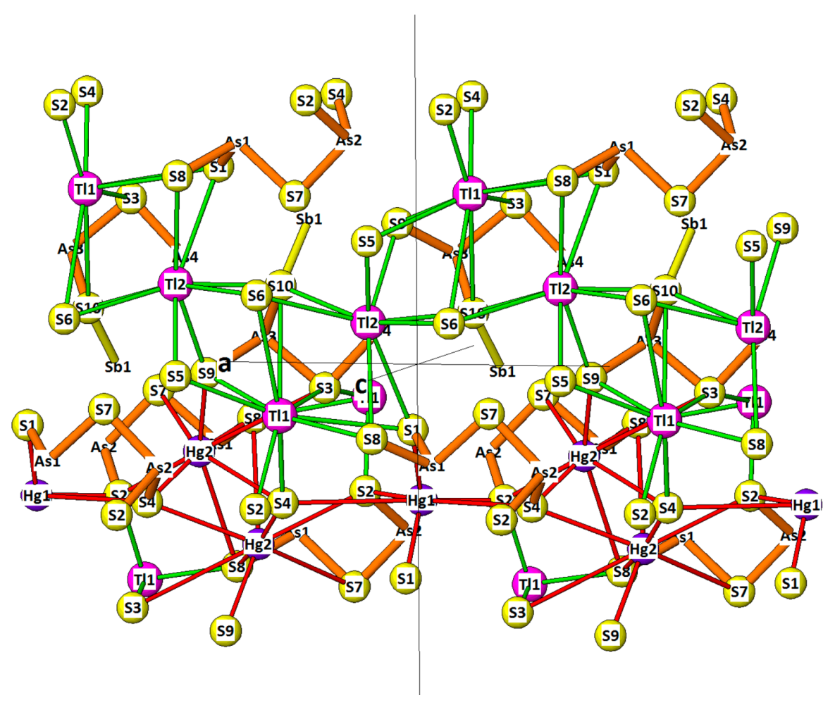
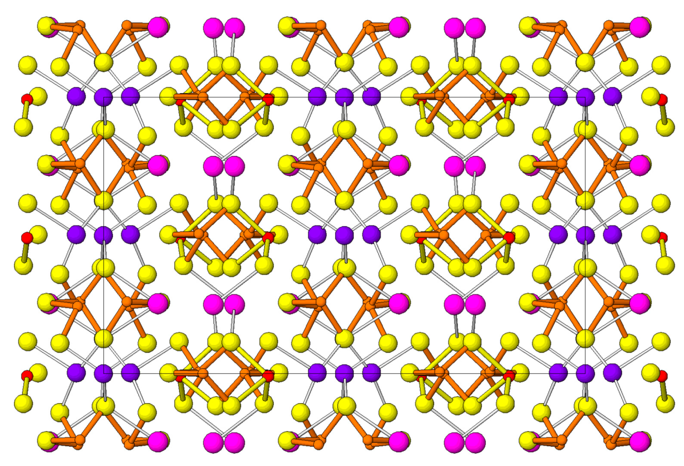
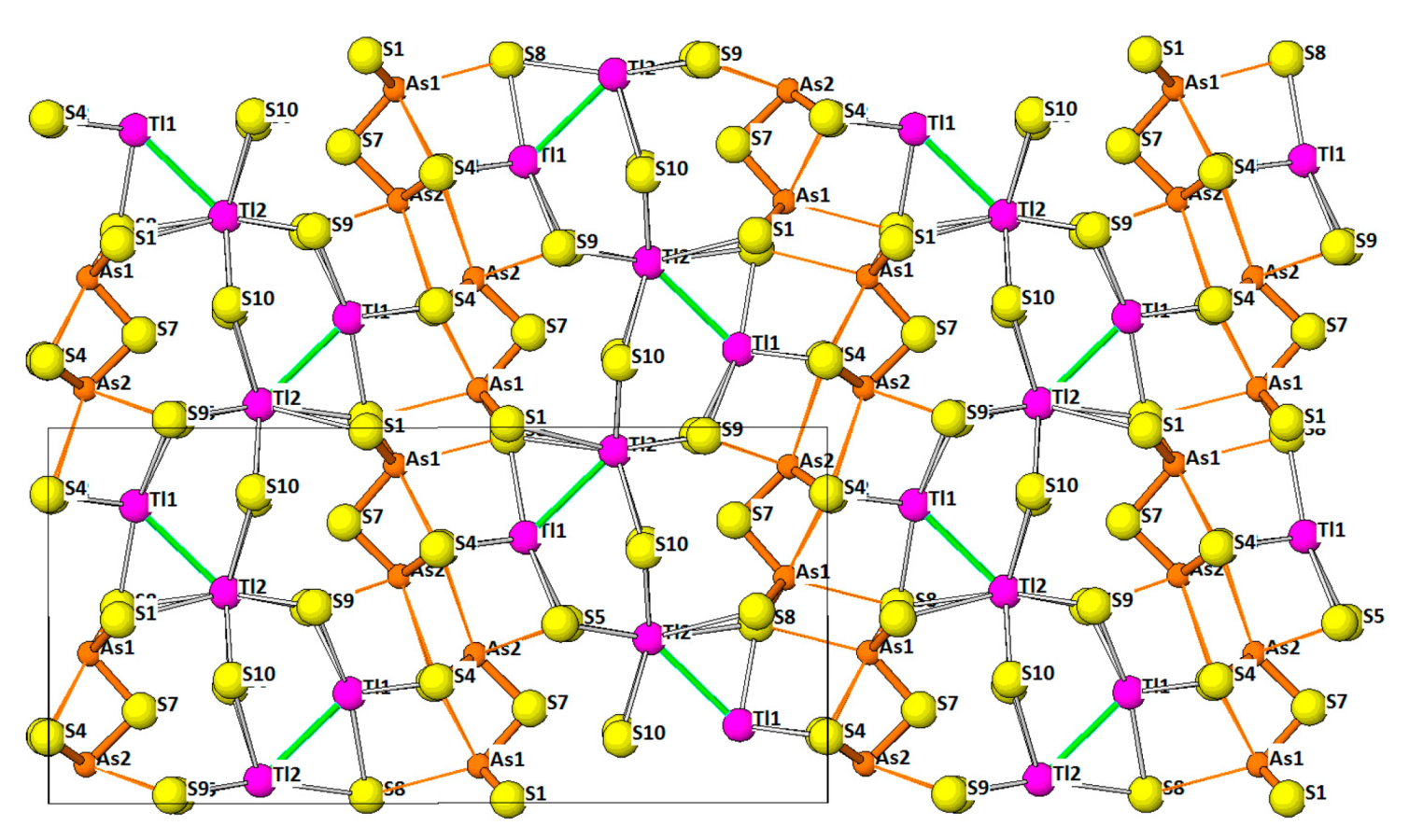
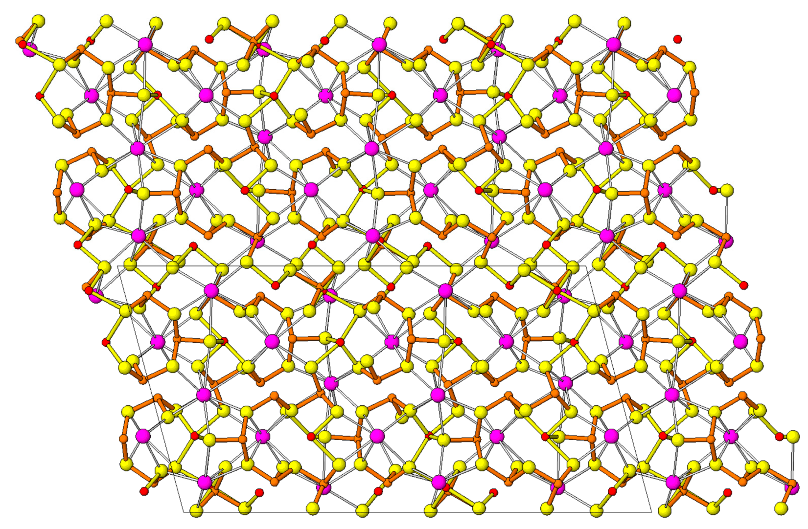
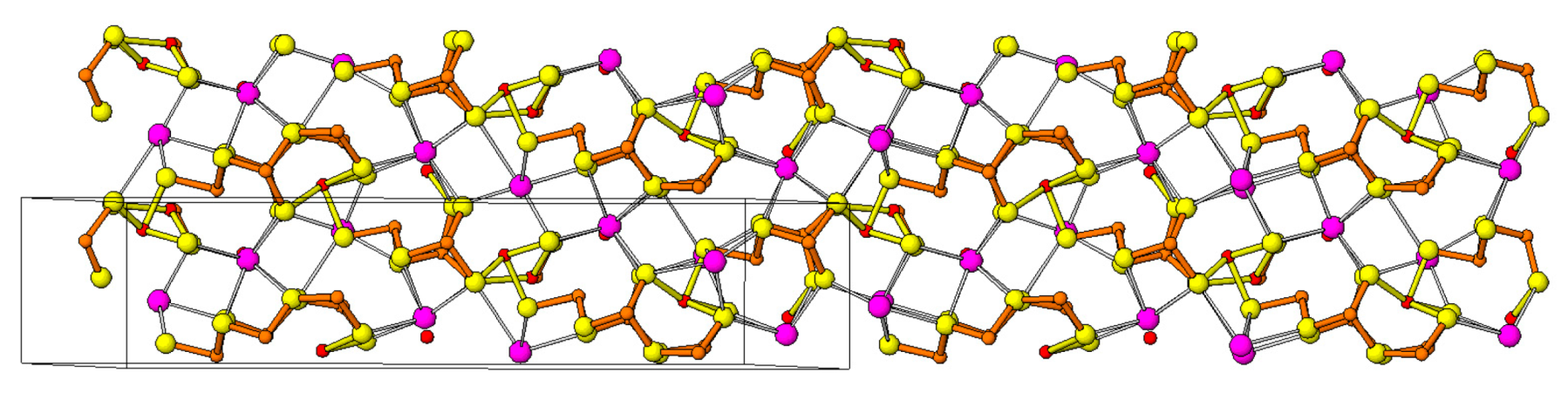
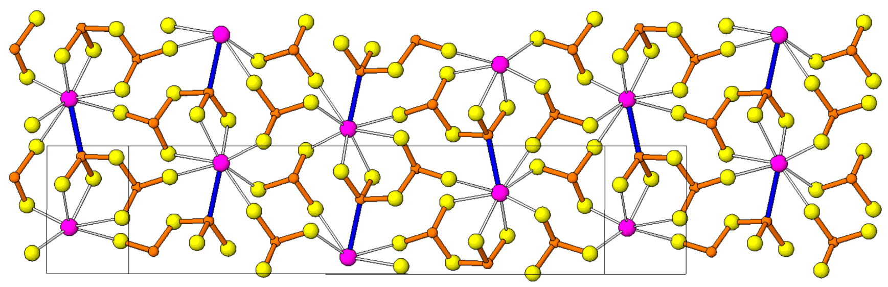
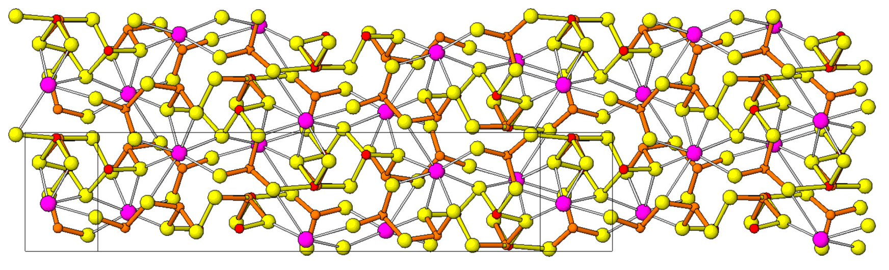
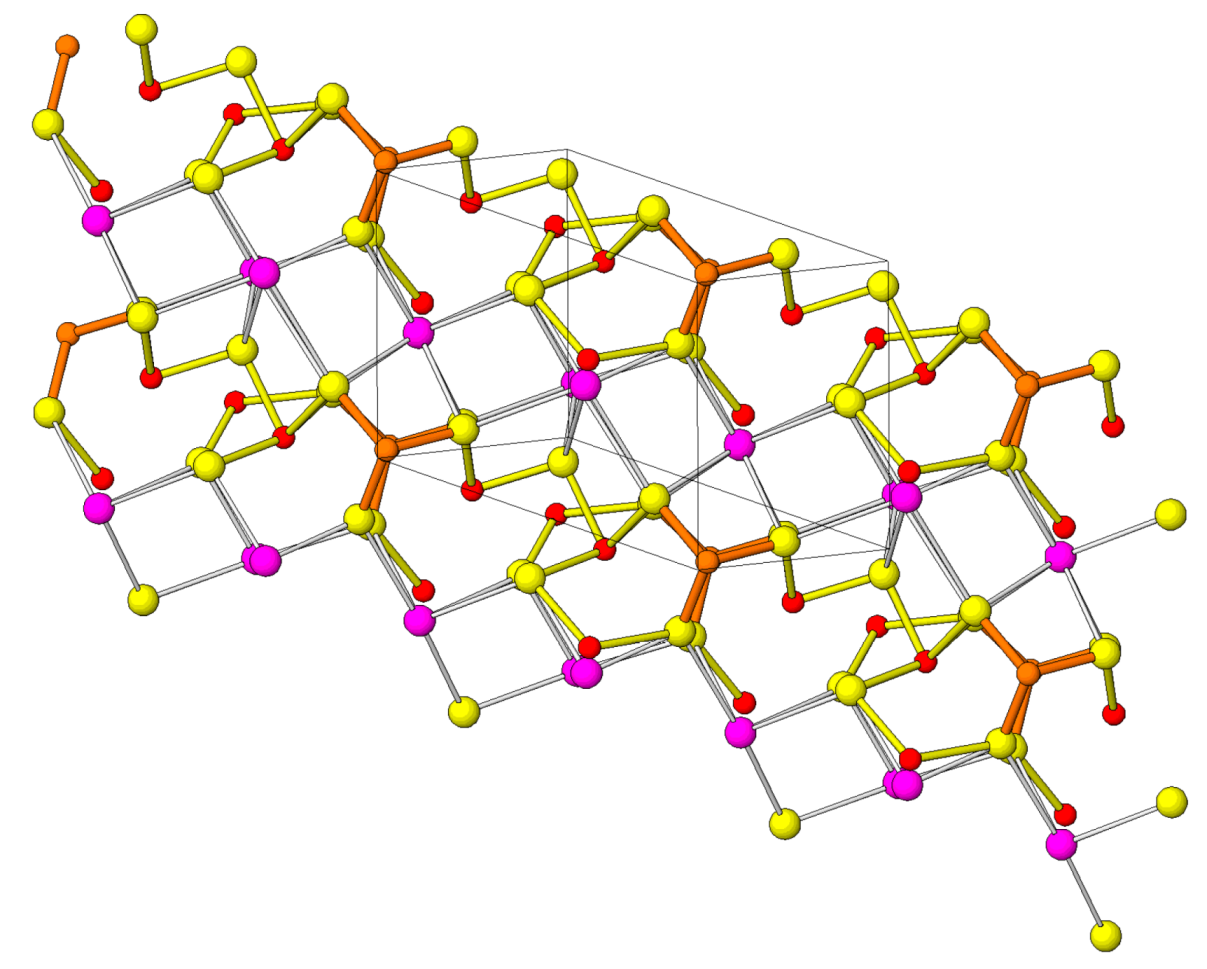
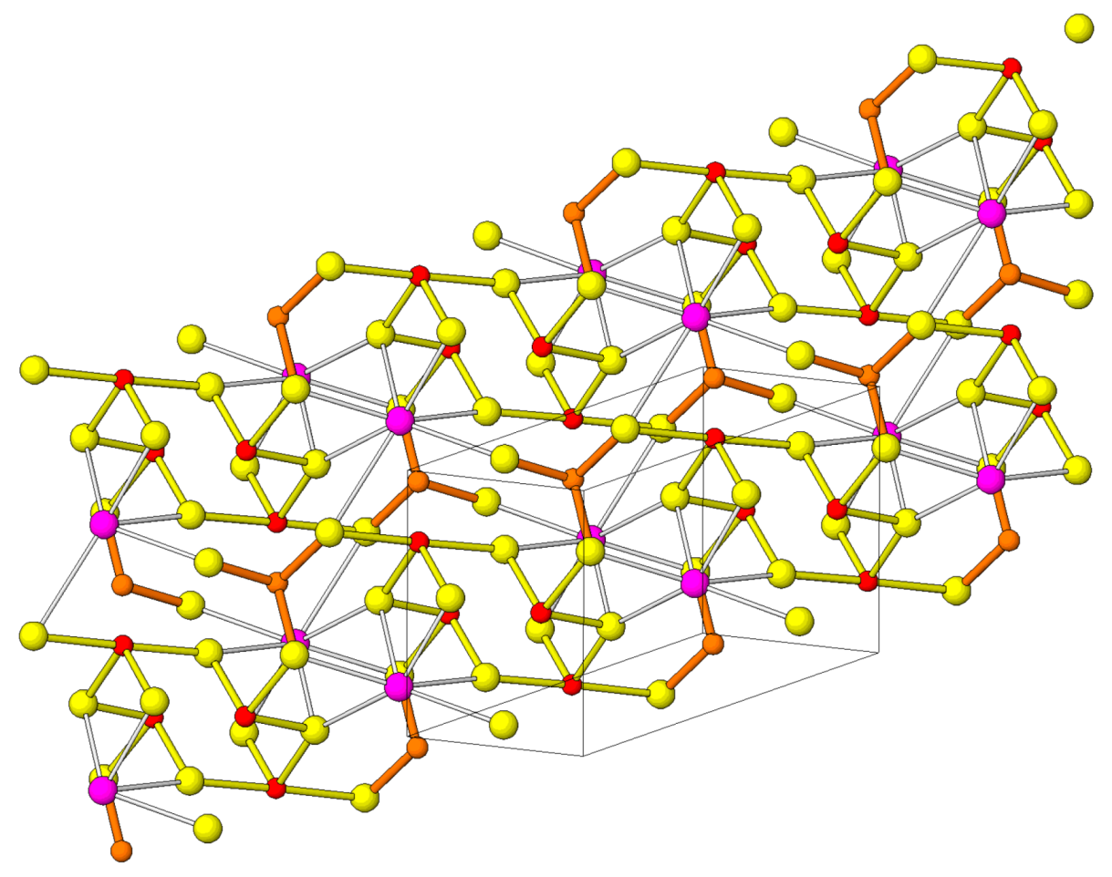
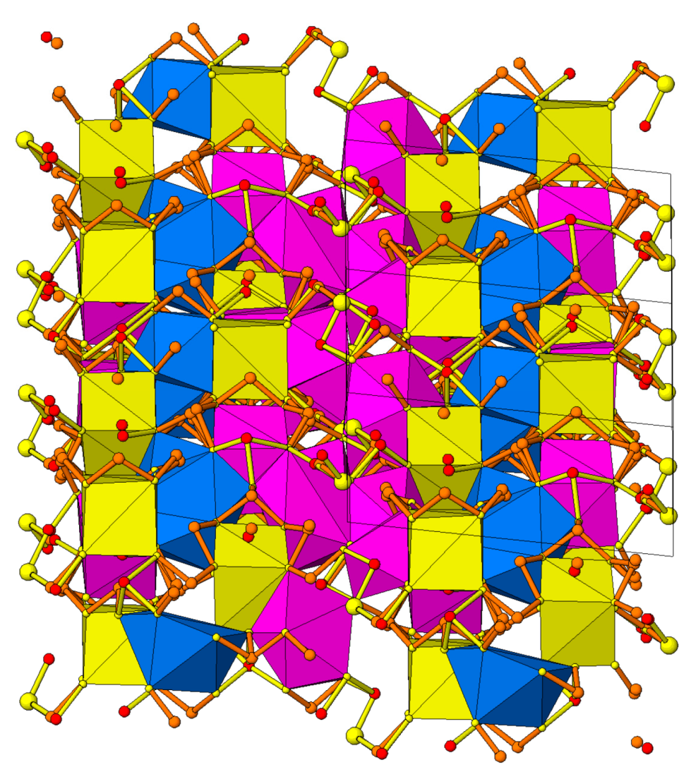
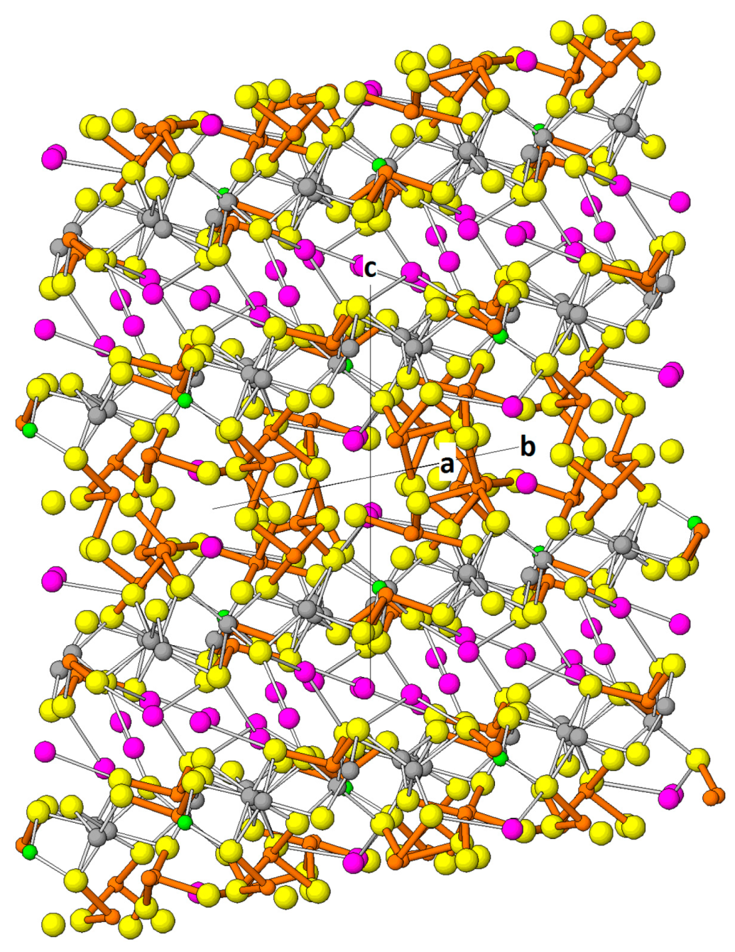
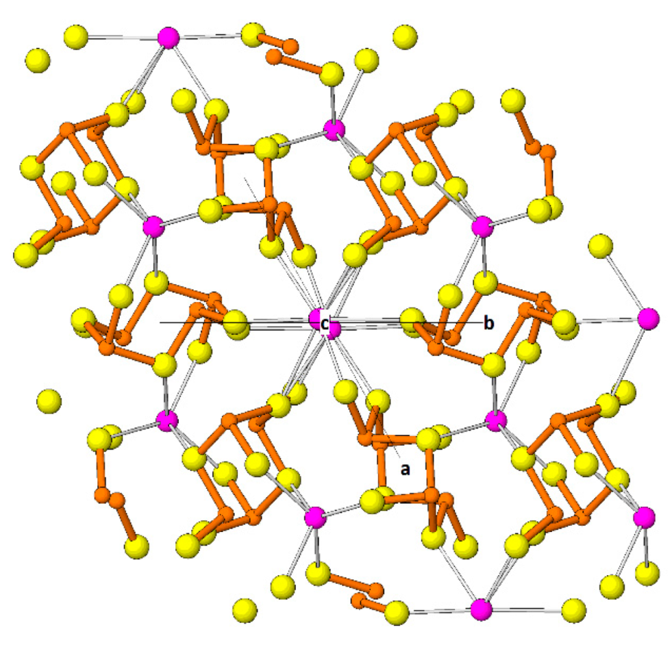
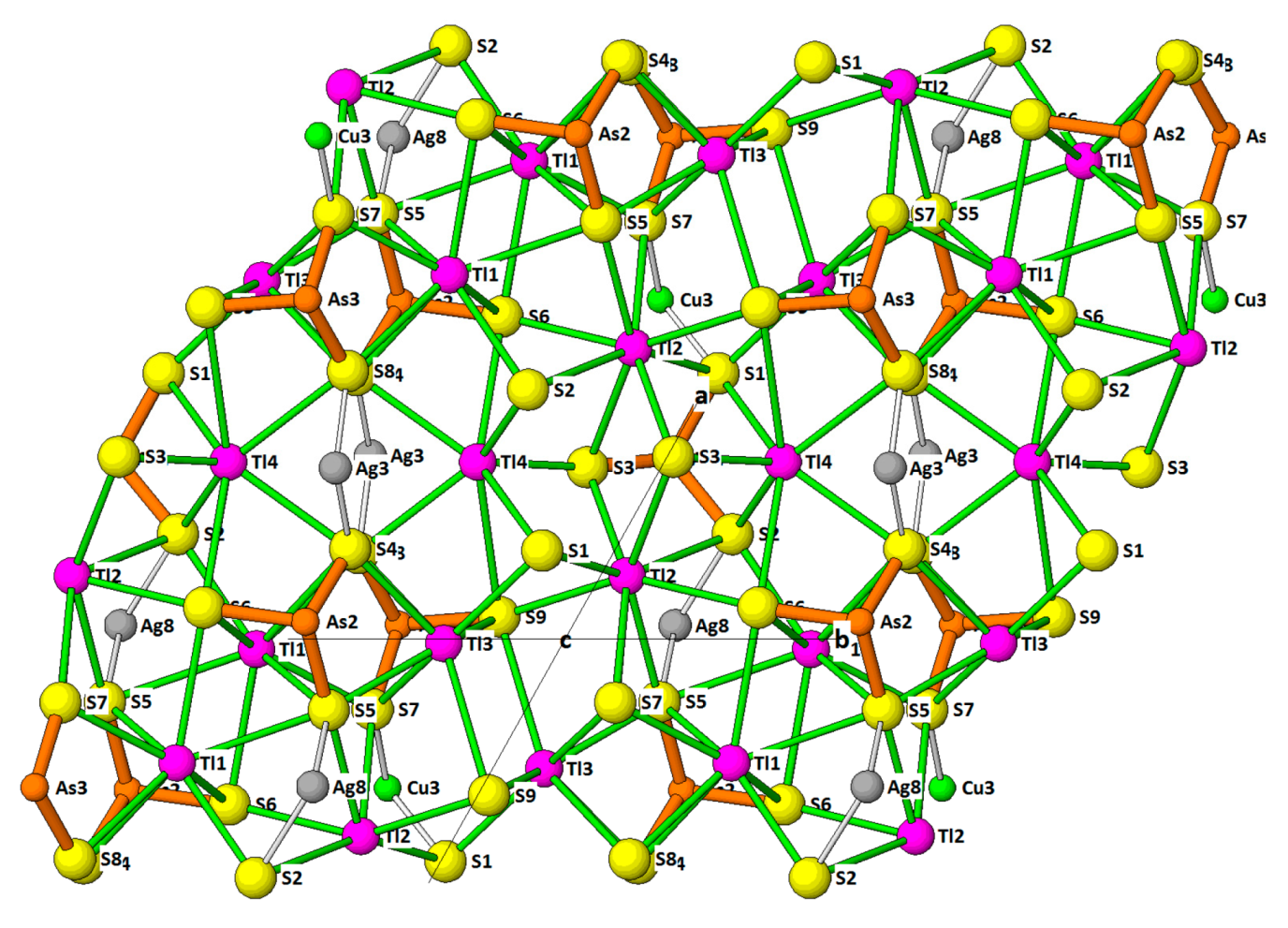
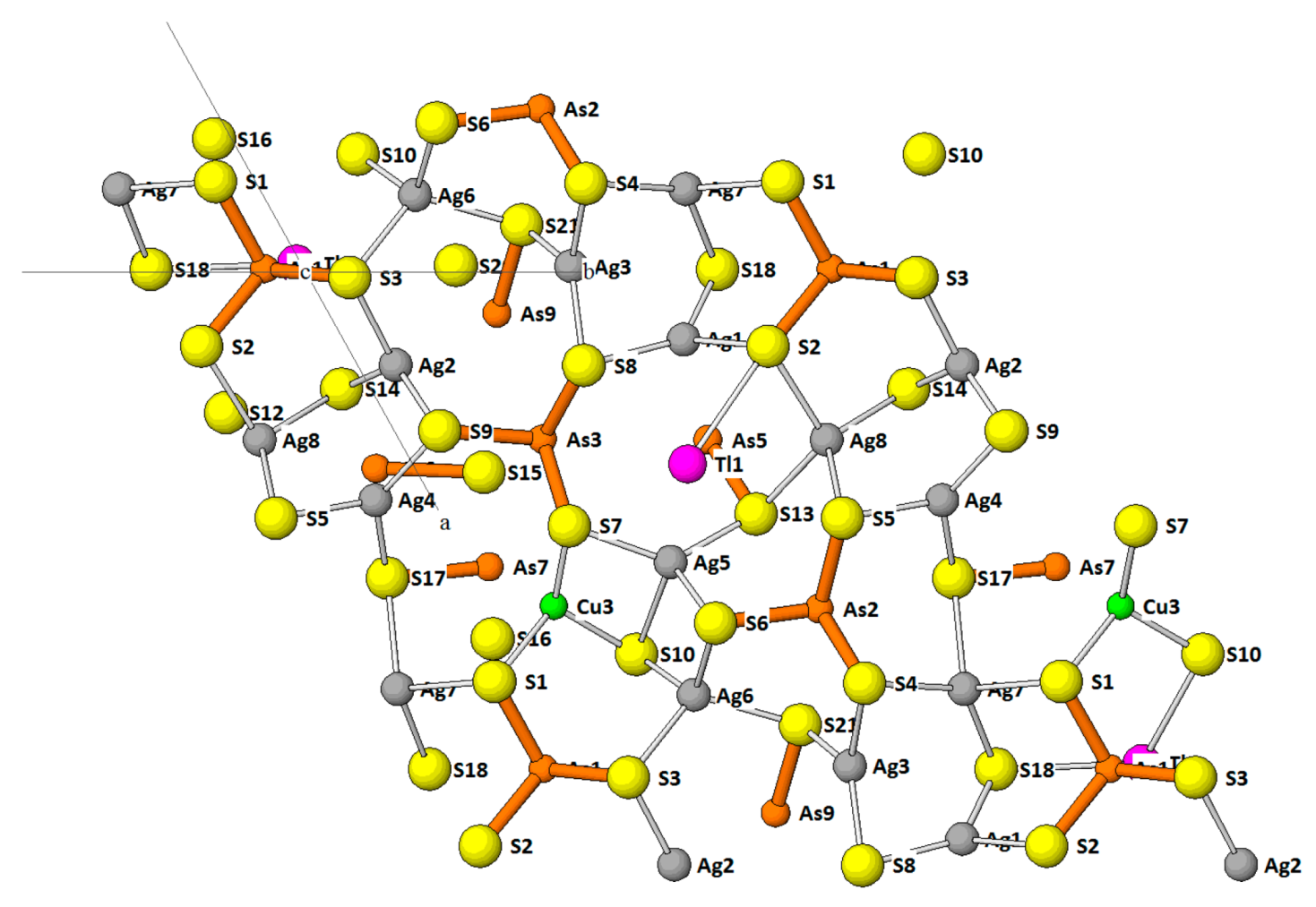
Table 1.
Minerals and synthetic phases dealt with in the review.
| Lorándite | TlAsS2 | galkhaite | (Cs,Tl)(Hg,Cu,Zn)6As4S12 |
| weissbergite | TlSbS2 | vorontsovite | Hg5CuTlAs4S12 |
| synth. | TlSbSe2 | ferrovorontsovite | Fe5CuTlAs2S12 |
| synth. | TlPbSbS3 | Kutinaite | (K,Tl)0.25Cu14Ag6.75 |
| Hutchinsonite | TlPbAs5S9 | Synth. | Tl3SbS3 |
| bernardite | TlAs5S8 | Parapierrotite | TlSb5S8 |
| imhofite | Tl5.6As15S25.3 | synth. | KSb5S8 |
| edenharterite | TlPbAs3S6 | synth. | (Tl0.6K0.4)Sb5S8 |
| jentschite | TlPbAs2SbS6 | protochabournéite | Tl2PbSb8.5As1.5S17 |
| Heptasartorite | Tl7Pb22As55S108 | chabournéite | ~Tl2PbSb6As4S17 |
| enneasartorite | Tl6Pb32As70S140 | dalnegroite | Tl4Pb2As12Sb8S34 |
| hendekasartorite | Tl2Pb48As82S172 | Tsygankoite | Mn8Tl8Hg2Sb21Pb2TlS48 |
| twinnite | Pb8Tl1As8Sb13S40 | rouxelite | Cu2HgPb22Sb28S64(O,S)2 |
| guettardite | PbSb1.1As0.8S4 | Simonite | TlHgAs3S6 |
| philrothite | TlAs3S5 | Synth. | TlBiS2 |
| dufrénoysite | Pb2As2S5 | Synth. | Tl3AsS3 |
| veenite | Pb16Sb9As7S40 | christite | HgTlAsS3 |
| rathite | Pb9.5TlAg2As18.5SbS40 | Synth. | Tl3Ag3Sb2S6 |
| pierrotite | Tl2(Sb,As)10S16 | synth. | Tl3Ag3As2S6 |
| baumauerite | Pb12As16S36 | Erniggliite | Tl2SnAs2S6 |
| Argentobaum-hauerite | Ag1.5Pb22As33.5S72 | synth. | TlMnAs2S5 |
| écrinsite | AgTl3Pb4As11Sb9S36 | raberite | Tl5Ag4As6SbS15 |
| boscardinite | AgTl3Pb4Sb14As6S36 | spaltiite | Cu2Tl2As2S5 |
| Sicherite | TlAg2(As,Sb)3S6 | wallisite | PbTl(Cu0.65Ag0.35)As2S5 |
| Andreadinite | CuHgAg7Pb7Sb24S48 | hatchite | PbTlAgAs2S5 |
| synth. | TlSb3S5 | richardsollyite | TlPbAsS3 |
| synth. | Tl4Bi2S5 | vrbaite | Tl4Hg3As8Sb2S20 |
| Gillulyite | Tl2(As,Sb)8S13 | rebulite | Tl5Sb5As8S22 |
| Routhierite | CuHg2TlAs2S6 | jankovićite | Tl5Sb10As3S22 |
| stalderite | CuZn2TlAs2S6 | gabrielite | Tl2AgCu2As3S7 |
| arsiccioite | AgHg2TlAs2S6 | ||
| ferrostalderite | CuFe2TlAs2S6 | ||
| ralphcannonite | AgZn2TlAs2S6 | ||
| tetrahedrite | Cu10(Fe,Zn)2Sb4S13 | ||
| tennantite | Cu10(Fe,Zn)2As4S13 | ||
| synth. | Cu10Hg2Sb4S13 |
Table 2.
Members of the hutchinsonite plesiotype family.
| Mineral | a (Å) | b (Å) | c (Å) | α (deg) | β (deg) | γ (deg) | Space Group | Reference |
|---|---|---|---|---|---|---|---|---|
| Hutchinsonite | 10.786 | 35.389 | 8.141 | Pbca | [26,27] | |||
| Bernardite | 15.647 | 8.038 | 10.750 | 91.27 | P21/c | [28] | ||
| Imhofite (*subcell) | 8.755 | 24.425 | 5.739 True cell 11.478 | 108.28 | P21/n* | [30,31] | ||
| Edenharterite | 47.453 | 15.476 | 5.847 | Fdd2 | [33] | |||
| Jentschite | 8.096 | 23.917 | 5.888 | 108.063 | P21/n | [32] |
Table 3.
Members of the sartorite homologous series quoted in this contribution.
| Mineral Homologue Order | a (Å) | b (Å) | c (Å) | α (deg) | β (deg) | γ (deg) | Space Group | Reference |
|---|---|---|---|---|---|---|---|---|
| Heptasartorite 3;3 | 29.269 | 7.877 | 20.128 | 102.065 | P21/c | [38] | ||
| Enneasartorite 3;3 | 37.612 | 7.878 | 20.071 | 101.930 | P21/c | [38] | ||
| Hendekasartorite 3;3 | 31.806 | 7.889 | 28.556 | 99.034 | P21/c | [37] | ||
| Twinnite 3;3 | 7.997 | 19.517 | 8.634 | 91.061 | P21/n | [39,40] | ||
| Guettardite 3;3 | 8.527 | 7.971 | 20.102 | 101.814 | P21/c | [40] | ||
| Philrothite 4;4 | 8.013 | 24.829 | 11.762 | 132.84 | P21/c | [41] | ||
| Dufrénoysite 4;4 | 7.90 | 25.740 | 8.37 | 90.35 | P21 | [42] | ||
| Rathite 4;4 | 8.496 | 7.969 | 25.122 | 100.704 | P21/c | [44] | ||
| Pierrotite 3;3 | 38.746 | 8.816 | 7.989 | Pna21 | [47,48] | |||
| Baumhauerite 3;4 | 7.884 | 8.345 | 22.811 | 90.069 | 97.255 | 90.082 | P1 | [51] |
| Argentobaumhauerite 3;4 | 7.905 | 8.468 | 44.410 | 84.614 | 86.469 | 89.810 | P-1 | [51] |
| Écrinsite 3;4 | 8.080 | 8.533 | 22.613 | 90.23 | 97.17 | 90.83 | P1 | [52] |
| Boscardinite 3;4 | 8.093 | 8.761 | 22.497 | 90.868 | 97.247 | 90.793 | P1 | [53,54] |
© 2018 by the author. Licensee MDPI, Basel, Switzerland. This article is an open access article distributed under the terms and conditions of the Creative Commons Attribution (CC BY) license (http://creativecommons.org/licenses/by/4.0/).
Share and Cite
MDPI and ACS Style
Makovicky, E. Modular Crystal Chemistry of Thallium Sulfosalts. Minerals 2018, 8, 478. https://doi.org/10.3390/min8110478
AMA Style
Makovicky E. Modular Crystal Chemistry of Thallium Sulfosalts. Minerals. 2018; 8(11):478. https://doi.org/10.3390/min8110478
Chicago/Turabian StyleMakovicky, Emil. 2018. "Modular Crystal Chemistry of Thallium Sulfosalts" Minerals 8, no. 11: 478. https://doi.org/10.3390/min8110478
Note that from the first issue of 2016, this journal uses article numbers instead of page numbers. See further details here.