
Reaction and Alteration of Mudstone with Ordinary Portland Cement and Low Alkali Cement Pore Fluids


Radionuclide Migration Research Group, Japan Atomic Energy Agency, Ibaraki 319-1194, Japan
*
Author to whom correspondence should be addressed.
Minerals 2021, 11(6), 588; https://doi.org/10.3390/min11060588
Submission received: 13 April 2021
/
Revised: 26 May 2021
/
Accepted: 26 May 2021
/
Published: 31 May 2021
(This article belongs to the Special Issue Clay Mineral Transformations after Bentonite/Clayrocks and Heater/Water Interactions from Lab and Large-Scale Tests)
Abstract
:The construction of a repository for the geological disposal of radioactive waste will utilize cement-based materials. Following closure, resaturation will result in the development of a highly alkaline porewater. The alkaline fluid will migrate and react with host rock, producing a chemically disturbed zone (CDZ) around the repository. To understand how these conditions may evolve, a series of batch and flow experiments were conducted with Horonobe mudstone and fluids representative of the alkaline leachates expected from a cementitious repository. Both ordinary Portland cement (OPC) and low alkali cement (LAC) leachates were examined. The impact of the LAC leachates was more limited than the OPC leachates, with experiments using the LAC leachate showing the least reaction and lowest long-term pH of the different leachate types. The reaction was dominated by primary mineral dissolution, and in the case of OPC leachates, precipitation of secondary calcium-silicate-hydrate (C-S-H) phases. Flow experiments revealed that precipitation of the secondary phases was restricted to close to the initial contact zone of the fluids and mudstone. The experimental results demonstrate that a combination of both batch and flow-through experiments can provide the insights required for the understanding of the key geochemical interactions and the impact of transport.
1. Introduction
The construction of a repository for geological disposal of radioactive waste will by necessity include the use of cementitious materials in a multiplicity of ways, such as fillers, liners, plugs, and seals [1,2,3,4]. Ordinary Portland cement (OPC)-based materials will be extensively used in the construction, and following closure, groundwater will saturate the repository and the use of OPC will result in the development of highly alkaline porewater (pH > 12.5), [5,6]. The alkaline fluid will migrate and react with the host rock to form a chemically disturbed zone (CDZ) around the repository [2]. A series of chemical gradients will develop over time and distance from the repository, disturbing the pH, redox, and fluid chemistry of the migrating fluid. It is important, particularly in the case of a radioactive waste repository, to understand the evolution of the CDZ in both time and space and subsequent impacts on the behavior and transport of any radionuclides in the CDZ.
The extent of the CDZ, beyond the host rock-cement interface, will depend upon several factors with both physical and chemical properties, i.e., host rock mineralogy, porosity/permeability, fracture density, groundwater composition, flow rates, and chemical buffering capacity. Previous studies have shown that in the host rock, silicate minerals dissolve in the highly alkaline pore fluid [2,7,8], followed by the precipitation of secondary minerals (calcium-silicate–hydrate, calcium-aluminum-silicate-hydrate (C-S-H, C-A-S-H), calcite) and aluminosilicates (zeolites, feldspars, feldspathoids) [9]. Other authors [10,11,12] have reported the interactions between cement pore fluids and argillaceous rocks, which demonstrated the alteration of argillaceous rocks by the high pH fluids and the buffering of the elevated pH by the clays and the reaction pathways. The degree of buffering and alteration of the primary minerals is dependent upon the starting mineralogy, i.e., clay mineral dissolution vs. carbonate reaction (including, when present, de-dolomitization [13]), cation exchange reactions, and the fluid chemistry, with Ca(OH)2-dominated fluids tending to result in greater formation of C-S-H phases.
The general sequence of reaction of host rock with OPC leachates is generally well understood [2,7,8,9]. The high pH develops from the leaching of the concretes and cements used in the waste containment and repository construction, resulting in primary mineral dissolution, which partly mitigates the high pH in the CDZ. This is then followed by secondary phase formation with OPC, particularly C-(A-)S-H phases and zeolites. The extent of the zone of interaction is dependent not only upon the host rock but also upon the reactant fluid chemistry. To mitigate the degree of alteration of the host rock, ‘low pH’ or ‘low alkali’ cements (LACs) have been developed to provide a target porewater pH < 11. LACs are based on pozzolanic cements with 30–80 wt% of the OPC clinker replaced by siliceous materials, such as silica fume (SF), fly ash (FA), blast furnace slag, and/or metakaolin. The high siliceous content in the LAC lowers the pH of the porewater by several complementary mechanisms. Firstly, the OPC content is reduced, and the pozzolanic reaction of silica with portlandite and calcium increases the C-S-H gel content. However, the extent of the reaction of host rock with LACs is less well understood. Studies have often been limited to batch experiments [14,15] or modelling studies [16]. In batch experiments conducted with Freedland Ton clay and a ‘low pH cement’ pore fluid [14], the clay did not undergo significant degradation. In other work examining the reaction zones at interfaces of Opalinus claystone (OPA) with two different concrete types (OPC and LAC) [17], again there was little evidence for chemical alteration of the claystone. Other batch experimental studies [15] have concluded that zeolitic phases would form in the interaction zones between rock-forming minerals and low-pH cements. In addition, some studies have focused on the degradation of the low-pH cement itself, e.g., [18], with clay pore fluids, rather than the impact on the host rock.
Unlike OPC, there is no standard LAC composition; different compositions of LAC have been considered by different radioactive waste disposal implementers. For example, many European operators are considering the use of LACs based on cement, silica, and blast furnace slag [19], whilst the LAC formulation, being considered for use in Japan, uses fly ash in place of the blast furnace slag. In Japan, the Japan Atomic Energy Agency (JAEA) developed a low alkaline cement called HFSC424 (high content fly-ash silica fume cement), composed of fly-ash (FA) 40 wt%, silica fume (SF) 20 wt%, and OPC 40 wt% [20,21], which results in a target porewater pH < 11.
Many previous studies have used only batch experiments to study the interaction of alkaline fluids with host rocks, since they are particularly suited to long duration studies, being simpler and easier to set up and maintain. The effects of time can be studied by running multiple identical experiments for differing durations [22]. In addition, elevated temperatures can be used to enhance mineral dissolution kinetics, speeding up reaction progress so that they may be observed more easily in the laboratory. Previously, batch experiments have been used to study the interactions between cement pore fluids and argillaceous rocks [10,11,12,18]. These studies demonstrated that the high pH leachates reacted with the argillaceous rocks, leading to the buffering of the elevated pH of the cement pore fluids by the clays and other host rock minerals, e.g., dolomite [13]. However, batch experiments, whilst useful, do not precisely replicate the sequence of mineral changes observed in the CDZ of a radioactive waste repository, since with batch experiments, the effects of transport are not addressed. In addition, batch experiments can be affected by the presence of transient phases or constrained availability of key components.
Flow-through experiments adapted from chemical engineering studies [23] are a useful technique to study transport processes, allowing the investigation of the spatial as well as temporal changes. Flow experiments are by their nature more complex than batch experiments and are best suited to shorter timescales, usually only a few months duration. Typically, a flow system set-up is comprised of a fluid reservoir, a pump to control flow rate, and the reactor itself with length scales of millimeters to meters. On completion of the experiment, it is possible to study the changes in mineralogy with distance by sectioning of the reacted solid. In addition, unlike batch experiments, it is possible to extract some physical properties from flow experiments, such as variations in porosity/permeability, using tracer tests. In addition, flow experiments can provide valuable well-constrained ‘test cases’ for the validation and calibration of reactive transport geochemical models. Such models may then be used, with increased confidence, to model the longer term evolution of the fluid rock interactions beyond that possible experimentally, which in the case of radioactive waste disposal extends to tens of thousands of years.
Flow-through column experiments have been used to investigate the reaction of cement pore fluids with single minerals and a variety of potential host rocks [24,25,26], but few previous studies have considered the impact on argillaceous rocks. This study, comparing the impact of leachates from traditional OPC-based materials with leachates from a LAC (specifically HFSC424) with a mudstone host rock used a combination of both batch experiments to provide an indication of the evolution of the alkaline leachate/mudstone system, together with flow-through experiments, which allowed the investigation of the spatial as well as temporal changes.
2. Materials and Methods
Samples of mudstone were collected from the Horonobe Underground Research Laboratory (URL) site, Hokkaido, Japan. The samples were taken from the gallery walls from the Koetoi formation, which is a massive and lithologically homogeneous, diatomaceous mudstone that contains amorphous silica (40–50 wt%), clay (17–25 wt%), quartz (7–10 wt%), and feldspar (5–10 wt%) [27,28]. The mudstone samples were crushed to <500 µm prior to being used in the experiments. Crushed materials were used, since the greater surface area allows greater (chemical) reaction and hence greater degree of reaction within the time constraints of a laboratory study. However, it is recognized that the crushing process could also result in the generation of ‘experimental artefacts’ by production of highly reactive ‘fines’.
Cement pore fluids representative of the alkaline leachates expected from a cementitious repository [29,30] were used in the batch and flow experiments. The first fluid represented a ‘young’ OPC leachate pH ~13.4 with high [Na] and [K]. A second fluid, an ‘evolved’ OPC leachate, was saturated with respect to portlandite, pH ~12.5. The third fluid represented the leaching of HFSC424 concrete with Horonobe groundwater, pH ~11 [21]. Details of the concentration of ions in the fluids are given in Table 1. The OPC leachates were prepared from analytical grade reagents; Na and K were added as hydroxides, and Ca as CaO. The HFSC424 leachate was prepared, under a N2 atmosphere, by equilibrating in equal masses, Horonobe groundwater, from the 07-V140-M03 borehole (located in the Koetoi Formation), with crushed HFSF424 concrete together, for 14 days before use.
2.1. Equipment
The batch experiments used in this study consisted of simple non-reactive equipment comprised of 50, 100, and 250 mL capacity polypropylene bottles. All experiments were conducted inside a glove box that was continuously flushed with N2. The primary aim of the flushing with N2 was to remove any carbon dioxide to prevent precipitation of CaCO3 from the alkaline leachates; a consequence of this was that oxygen levels also remained low (<0.5%), but no attempt was made to impose redox control. The oxygen concentration inside the glove box was monitored using a JIKCO JKO-02LJD3 meter/sensor combination (ICHINEN JIKCO Co., Ltd., Shibaura, Japan). Fluid:solid (F:S) ratios, ranging from solid to fluid dominated systems, of 1:1, 10:1, and 100:1 (mL:g) were used, with typical durations for the experiments of 24 h, and 7, 28, and 56 days. All batch experiments were performed at lab temperature of ~24 °C. On termination of the batch experiments, the fluids were sampled within the N2 glove box, and the solids were recovered by filtration and then vacuum dried before being prepared for subsequent mineralogical analysis.
As well as batch experiments, flow-through experiments with continuous collection of reacted fluids allowing the changes in fluid chemistry to be tracked over time were also conducted. As with the batch experiments, the reacted solid was only sampled on termination, but by sectioning of the reacted solids, it was possible to study the changes in mineralogy with distance. Two different approaches were used in this study for the flow experiments. The first was comprised of PEEK (polyetheretherketone) columns (300 mm long, and 7.5 mm i.d.) packed with crushed mudstone and connected to fluid reservoirs and sample collection bottles (Figure 1). Similar experimental equipment has been used in other studies [24,25,26] to examine the impact of alkaline fluids on potential host rock materials. The second approach consisted of a small flow cell (SFC) constructed from acrylic plastic and sealed by a combination of ‘O-rings’ and bolts (Figure 1). Filters and porous polypropylene disks (on both inlet and outlet sides) acted both to distribute the incoming fluid across the whole face of the mudstone sample and prevent blockage of the outlet tubing. An advantage of the SFC equipment was the larger diameter of the cell, which reduced the chance of blockages forming due to movement of ‘fines’, preventing flow through the cell. A slight disadvantage was the reduced sample length (only 10 mm compared to the 300 mm length of the columns). Table 2 gives a comparison between the physical parameters for the different flow equipment. For both flow setups, the volumetric flow rate was typically ~0.5 mL per hour (~12 mL per day). Flow for both types of equipment was controlled by a Cole-Parmer MASTERFLEX® peristaltic pump (Cole-Parmer, Vernon Hills, IL, USA). Although fast compared to the flow rates likely to be encountered in a radioactive waste repository, the flowrate chosen was a compromise between maintaining the lowest possible steady flow rate with the peristaltic pump and maximizing the number of pore volumes passing through the flow experiments in a laboratory time frame. Periodically, the reacted fluids from the flow experiments were sub-sampled and prepared for chemical analysis. As with the batch experiments, the flow experiments were again performed at lab temperature of ~24 °C.
2.2. Analysis
All collected fluids were filtered using 0.2 µm syringe filters and then sub-sampled for determination of cations and anions. Typically, a 4 mL sample of the fluid was diluted two-fold with 18 MΩ demineralized water (Millipore Simplicity® ultrapure water system) and then acidified with concentrated HNO3 (1% v/v) to preserve the sample. This sample was used for the analysis of major cations by a combination of ICP-OES (inductively coupled plasma-optical emission spectrometry) using a Shimadzu ICPE-9800 (Shimadzu Corporation, Kyoto, Japan), and ICP-MS (inductively coupled plasma-mass spectrometry), using a Perkin-Elmer NexION 300x (PerkinElmer, Inc., Waltham, MA, USA), both calibrated using matrix matched standards. A second subsample was taken for determination of major anions by IC (ion chromatography) using a Dionex ICS-5000 (Thermo Fisher Scientific, Waltham, MA, USA) ion chromatograph system calibrated using a mixed standard solution (Kanto Chemical Co., Inc, Tokyo, Japan). All fluid samples were stored at <5 °C until required for analysis.
The pH of the experimental fluids was determined immediately upon sampling using a DKK-TOA Corp. model HM-30P meter and combination electrode calibrated using DKK-TOA Corp. buffers at 4.01, 6.86, and 9.18 pH (Japanese standard), pH accurate to ±0.02 pH.
On completion of the flow experiments, columns were sectioned into ~15 mm long pieces using a small rotary cutting saw (Proxxon KG 50, Kiso Power Tool Co., Ltd, Osaka, Japan) and then vacuumed dried before being prepared for subsequent mineralogical analysis. The samples from the SFC were vacuumed dried, whilst still held in the central section, before being carefully extruded and sectioned into ~1.5 mm thick slices using a thin blade. Samples from the batch experiments were filtered to remove excess fluid and then vacuumed dried.
Once dried, the solid samples were prepared for petrographic analysis by a combination of scanning electron microscopy (SEM), using a JEOL JSM-6510 Series SEM, (JEOL Ltd., Tokyo, Japan) and X-ray diffraction (XRD) analysis (RigaKu SmartLab XRD, Rigaku Corporation, Tokyo, Japan), with a 9 kW X-ray source). Sub-samples for SEM analysis were prepared as either gold or carbon coated random mount stub samples. Techniques included SEM using both secondary electron imaging (SE) and backscattered electron (BSE) imaging, and element distribution analysis using energy-dispersive X-ray spectroscopy (EDS). Samples for XRD were prepared for analysis by taking a representative sub-sample and grinding it to a fine powder.
The saturation indices (SI = log (IAP/Ks), where IAP: ion activity product; Ks: solubility constant) of the primary and potential secondary minerals, in the reacted fluids, were calculated using the PHREEQC v3.6.3 geochemical code [31]. Calculations were performed using the JAEA thermodynamic database (TDB) [32]. JAEA-TDB version PHREEQC 19.dat (v1.2, 03.Mar.2020) was used for the calculations, being the latest version available at the time.
3. Results
3.1. Aqueous Chemistry
3.1.1. Changes in pH
The changes in pH with time for the batch and flow experiments are shown in Figure 2a. In the 1:1 F:S batch experiments, a large decrease in pH was observed, with the greatest change being seen in the experiments with the HFSC424 leachate (pH ~3.5) compared to the experiments with the OPC leachates. The pH reduction in the 10:1 F:S experiments was smaller, and again so in the 100:1 F:S experiments. In all cases, the pH drop was the least in the experiments with the ‘young’ OPC leachate and greatest with the HFSC424 leachate. In the 100:1 F:S experiments with the ‘young’ OPC leachate, the pH was only ~0.2 pH units below the initial leachate.
In all the flow experiments, there was an initial drop in pH before it later recovered to around ~0.2 pH units below that of the initial fluids. These initial changes in pH were similar to those seen in the equivalent 1:1 batch experiments, and the later ‘steady-state’ pH was similar to that observed in the 100:1 F:S batch experiments. Again, as with the batch experiments, the initial decrease was greatest in the experiments with the HFSC424 leachate.
Since the Horonobe mudstone contains a small amount of pyrite (<2 wt%) [27,28], and the samples used here had not been preserved in a reducing environment, it is highly likely that the low pH seen in some batches and all flow experiments were due to the dissolution of sulphate phases formed by the oxidation of pyrite during sample storage and preparation. Indeed, corresponding increases in [SO42–] up to ~8000 mg/L in the 1:1 batch experiments, and in the first two days of the flow experiments, were seen in the fluids with low pH, and XRD analysis (Figures S1 and S2) of the unreacted mudstone indicated the presence of jarosite and/or gypsum. Previous analysis of cores from Horonobe [33] have also shown the oxidation of pyrite and the precipitation of calcium sulphates such as gypsum.
3.1.2. Changes in Na Concentration
The variation in Na concentration is shown in Figure 2b. With the ‘young’ OPC leachate, the concentrations of Na in the 100:1 and 10:1 F:S batch experiments (which were fluid dominated) were close to that of the initial leachate (~1500 mg/L), but the 1:1 F:S experiments showed increases in [Na] compared to the initial leachate, up to ~2600 mg/L. A similar increase in [Na] was seen in the 1:1 F:S experiments with the ‘evolved’ OPC leachate (from below detection to ~1500 mg/L), with a smaller ~200 mg/L increase seen in the 10:1 F:S but no change in the 100:1 F:S experiments.
With the HFSC424 leachate, again there was an increase in the [Na] in the reacted fluids in the 1:1 F:S experiments, to ~3600 mg/L, but in the 10:1 and 100:1 F:S experiments, there was a ~300 mg/L decrease. In the flow experiments (Figure 2b), there was an initial decrease in [Na] with both the ‘young’ OPC and HFSC424 leachates from ~1500 to ~1300 mg/L and from ~3300 to 1200 mg/L, respectively. The Na concentrations in both fluids then slowly increased over the next 16 d until the concentrations were close to but still below those of the original leachates.
3.1.3. Changes in K Concentration
In the batch experiments (Figure 2c), with the ‘young’ OPC leachate, [K] decreased, most notably so in the 1:1 F:S experiments where concentrations dropped to ~2000 mg/L. Smaller decreases were seen in the higher F:S experiments, with [K] in the 100:1 F:S experiments being slightly below the initial concentrations. With the ‘evolved’ OPC leachate, [K] was typically <100 mg/L. In the case of the HFSC424 leachate, [K] decreased in all the batch experiments, from ~1330 to <150 mg/L.
In the flow experiments (Figure 2c) with the ‘young’ OPC leachate, [K] decreased initially by around 1300 mg/L, but in the later fluids, there was only a slight decrease compared to the initial leachate concentration. With the HFSC424 leachate, [K] in the reacted fluids flow experiments decreased from the initial concentration to <1 mg/L.
3.1.4. Changes in Ca Concentration
The behavior of Ca in the batch experiments was more complex than that of the other alkali metals (Figure 2d). With the ‘young’ OPC leachate, in the 1:1 F:S experiments, [Ca] increased to ~250 mg/L after 56 d. However, in the higher F:S experiments, [Ca] decreased to below that of the ‘young’ OPC leachate, i.e., <2 mg/L after 56 days. With the ‘evolved’ OPC leachate, [Ca] initially decreased significantly, the largest decreases to ~44 mg/L being seen after 24 h in the 1:1 experiments. In the longer duration 1:1 and 10:1 F:S experiments, [Ca] then increased to 470 and 240 mg/L, respectively, but remained below that of the original OPC leachate. In the 100:1 F:S experiments, [Ca] remained low (<100 mg/L) and did not recover with time.
In the flow experiments with the ‘young’ OPC leachate (Figure 2e), [Ca] decreased from the original leachate, stabilizing at ~25 mg/L after ~16 d. In the flow experiments with the HFSC424 leachate, [Ca] increased from ~100 mg/L to ~500 mg/L before decreasing to similar concentrations (~25 mg/L), as seen in the OPC leachate flow experiments.
3.1.5. Changes in Silica Concentration
In the 1:1 F:S batch experiments with the ‘young’ OPC leachate, silica concentrations (Figure 2f) initially increased to ~300 mg/L but then decreased over time to ~80 mg/L. However, with the ‘young’ OPC leachate, very high silica concentrations were observed in the 28 and 56 d, 10:1 F:S batch experiments, ~10,000 mg/L (inset in Figure 2f) and <2000 mg/L in the 100:1 experiments. Concentrations in the batch experiments with the ‘evolved’ OPC leachate were significantly lower, at <100 mg/L. In the HFSC424 leachate batch experiments, silica concentrations remained close to or lower than the original leachate.
In the flow experiments with the ‘young’ OPC leachate (Figure 2e), the dissolved silica concentration initially increased to ~3800 mg/L in the column experiment, and ~1900 mg/L in the SFC experiment; thereafter, the concentration of silica in the fluids decreased to ~1300 mg/L in the columns and <300 mg/L in the SFC. The higher silica concentrations observed in the columns, compared to the SFC experiments, reflects the greater mass of mudstone in the columns as well as the longer residence time (Table 2). In both HFSC424 leachate flow experiments (Figure 2e), silica concentrations were always lower than the original HFSC424 leachates, and significantly lower than with the ‘young’ OPC leachate.
3.1.6. Changes in Other Cations
Dissolved iron tracked the dissolution of sulphate (see Section 3.1.1) with increases in [total Fe] up to ~250 mg/L in the 1:1 batch experiments, and in the first two days of the flow experiments, coinciding with the changes in sulphate concentrations. In all the flow experiments following the peak in [total Fe], the concentration in the reacted fluids decreased to <0.01 mg/L by ~16 d of flow (equivalent to ~50 pore volumes).
With the exception of Rb and Sr, which tracked the concentrations of Na and Ca, respectively, the concentrations of other cations analyzed (e.g., Al, Ba, Cs, Cu, Li, Mg, Mn, Ni, Pb) were either below detection or showed no significant change from the original leachates.
3.1.7. Changes in Anions
As previously mentioned, increases in sulphate concentration, due to presence of pyrite, were seen in the fluids that had low pH values. However, chloride, which is a component of the Horonobe groundwater and therefore present in the HFSC424 leachate, behaved in a conservative manner, remaining close to the concentration of the initial HFSC424 leachate. The other anions analyzed (Br, F, NO3–,NO2–, and PO43–) were either below detection or showed no significant change from the original leachates.
3.2. Solid Analysis
3.2.1. Batch Experiments
Samples from the 1:1 F:S batch experiments with the ‘young’ OPC leachate were analyzed by SEM, including EDS and XRD. There was evidence of primary material dissolution (removal of fine material present in the original mudstone), but SEM–EDS analysis found no evidence for the formation of secondary phases. XRD analysis (Figure S1) of the unreacted mudstone indicated the presence of jarosite and/or gypsum alongside the primary minerals. XRD analysis of the reacted solids (Figure S1) was less informative; the main peaks identified were those of the original primary minerals, though some peaks could be attributed to crystalline C-S-H phases, but the relative peak intensities were too low to make a definitive interpretation. In addition, since many C-S-H phases are amorphous gels, XRD is of limited value.
In the higher F:S ‘young’ OPC leachate experiments, again the absence of fines suggested primary mineral dissolution, but only in the experiments with the ‘evolved’ OPC leachates was evidence found by SEM EDS analysis for secondary C-(A-)S-H phases (Figure 3); semi-quantitative analysis gave Ca:Si ranging from 0.89 to 1.1. In the batch experiments with the HFSC424 leachates, no mineralogical evidence (SEM observations and analysis by SEM-EDS, and XRD) was found for the formation of any secondary C-S-H phases.
3.2.2. Flow Experiments
A summary of the evolution of the mineralogical analysis from the column experiment with the ‘young’ OPC leachate is shown in Figure 4. Section 1 of the column (~0–20 mm) under SEM analysis showed extensive precipitation of secondary C-S-H and C-A-S-H gel-like (hydrous) phases (Figure 4) with different Ca:Si ratios (from 0.5 to 1.4). However, SEM examination of the remaining sections of the column showed no evidence of further precipitation of any secondary phases, and only the presence of the primary mineral phases (Figure 4), some of which appeared to be free of fines, suggesting a degree of mineral dissolution.
The equivalent experiment was performed using the SFC with the ‘young’ OPC leachate (Figure 5). In Section 1 (~0–1.5 mm) under SEM observation, only primary minerals and diatom fragments present in the original mudstone [28] were visible (Figure 5); there was no evidence (SEM EDS element mapping) found for the formation of any secondary phases. However, in Section 2 (~1.5–3 mm), a variety of secondary C-S-H and C-A-S-H phases (Ca:Si 0.5–0.7) were observed (Figure 5). In examination by SEM of Sections 3–6 (3–10 mm), no secondary phase(s) were observed, and the primary mineral surfaces showed little sign of reaction.
In the SFC experiment using the HFSC424 leachate (Figure 6) in Section 1 (~0–2.5 mm) and Section 2 (~2.5–5 mm), unlike the equivalent experiment with the ‘young’ OPC leachate (Figure 5), only primary minerals, which were relatively free of fines, were present. Additionally, there was no mineralogical evidence (SEM observations and SEM-EDS element mapping) for the precipitation of any secondary C-S-H phases, though occasional very rare crystals with zeolitic-type compositions were detected by SEM-EDS analysis.
All of the solids from the flow experiments were also examined by XRD, but the results were inclusive with the main peaks present belonging to the primary minerals (e.g., SFC experiment with the ‘young’ OPC leachate, Figure S2), and as in the batch experiments, although some peaks could be attributed to C-S-H phases, the relative peak intensities were again too low to make a definite interpretation.
4. Discussion
4.1. Chemical Evolution and Buffering Behavior
In this study, using samples of Horonobe mudstone, both OPC and LAC leachate types showed a similar behavior with regard to pH trends (see Figure 2a and Section 3.1). The longer term reduction in pH was not as large as seen in some other studies of argillaceous clays, such as the Opalinus claystone (OPA) [13], but unlike the Horonobe mudstone, OPA also contained significant dolomite that reacted to form calcite and precipitate Mg-hydroxides, which aided the reduction in pH. However, the longer-term pH changes were similar to those seen in other studies using OPC type leachates with a variety of mineralogies [24,25,26].
With regard to the behavior of both Na and K (Figure 2b,c) in the absence of any identifiable K- or Na-bearing secondary precipitates, the initial decreases in their concentrations observed in both the batch experiments and the early stages of the flow experiments suggests possible ion exchange reactions with the clays in the mudstone. In the flow experiments, the latter recovery of [Na] and [K] (Figure 2b,c) suggests that all the accessible exchangeable sites may have been occupied. In the case of the Horonobe mudstone, Koetoi formation, studied here, smectite typically represents ~10 wt% of the primary minerals [27,28]. Ion exchange has been identified in other studies on argillaceous clays [13,34], in which it was demonstrated to have a significant impact on the fluid chemistry, but it was not possible to confirm the ion exchange by cation exchange capacity analysis in these experiments due to the small solid sample size (in particular for the flow experiments) available.
The trend in [Ca] (Figure 2d,e) was thus complicated by the apparent ion exchange reactions. The observed increases in [Ca] in the 1:1 F:S batch experiments (both ‘young’ OPC and HFSC424 leachates) and the initial stages of the flow experiments were likely due to ion exchange. However, with both ‘young’ OPC and HFSC424 leachates, the latter Ca concentrations in the flow experiments and those in the higher F:S batch experiments decreased, which would indicate the precipitation of Ca-bearing phase(s). In contrast, in all the batch experiments with the ‘evolved’ OPC leachate, [Ca] in the reacted fluids was always lower than the original leachate, again suggesting the formation of Ca-bearing secondary phase(s). Taken together with the changes in silica concentrations in the experiments, it is likely that the secondary phase(s) would be C-S-H phases.
The continued presence of dissolved silica in the flow experiments suggests that there was continued dissolution of the primary silicate phases present in the mudstone, and this was most significant with the highly alkaline ‘young’ OPC leachate.
4.2. Mineral Dissolution and Precipitation Processes
In terms of mineralogical observations, in all the experiments there was SEM evidence for primary mineral dissolution (Figure 3, Figure 4, Figure 5 and Figure 6), but only in the flow experiments with the OPC leachate and in some of the higher F:S batch experiments was secondary phase formation observed. These were comprised of C-(A)S-H phases of differing morphologies (see Figure 3, Figure 4 and Figure 5), from ‘gel-like’ to more ‘fibrous’ phases and C-S-H ‘balls’, of varying Ca:Si ratios. In the experiments with the HFSC424 leachates, there was little analytical mineralogical evidence to support secondary phase formation.
As noted above, the changes in [Ca] and the relationship with dissolved silica suggests the formation of Ca-silicate phases in most of the experiments, most likely secondary C-S-H and C-A-S-H phases, though they were only directly observed in the experiments with the OPC leachates. The elevated silica concentrations most likely reflect the dissolution of the primary amorphous silica and aluminosilicate minerals.
Aluminum concentrations would be expected to increase alongside silica due to dissolution of the primary aluminosilicates, so the absence of Al in the fluids suggests the preferential dissolution of the amorphous silica or possible incorporation in secondary minerals, such as C-A-S-H phases or zeolites.
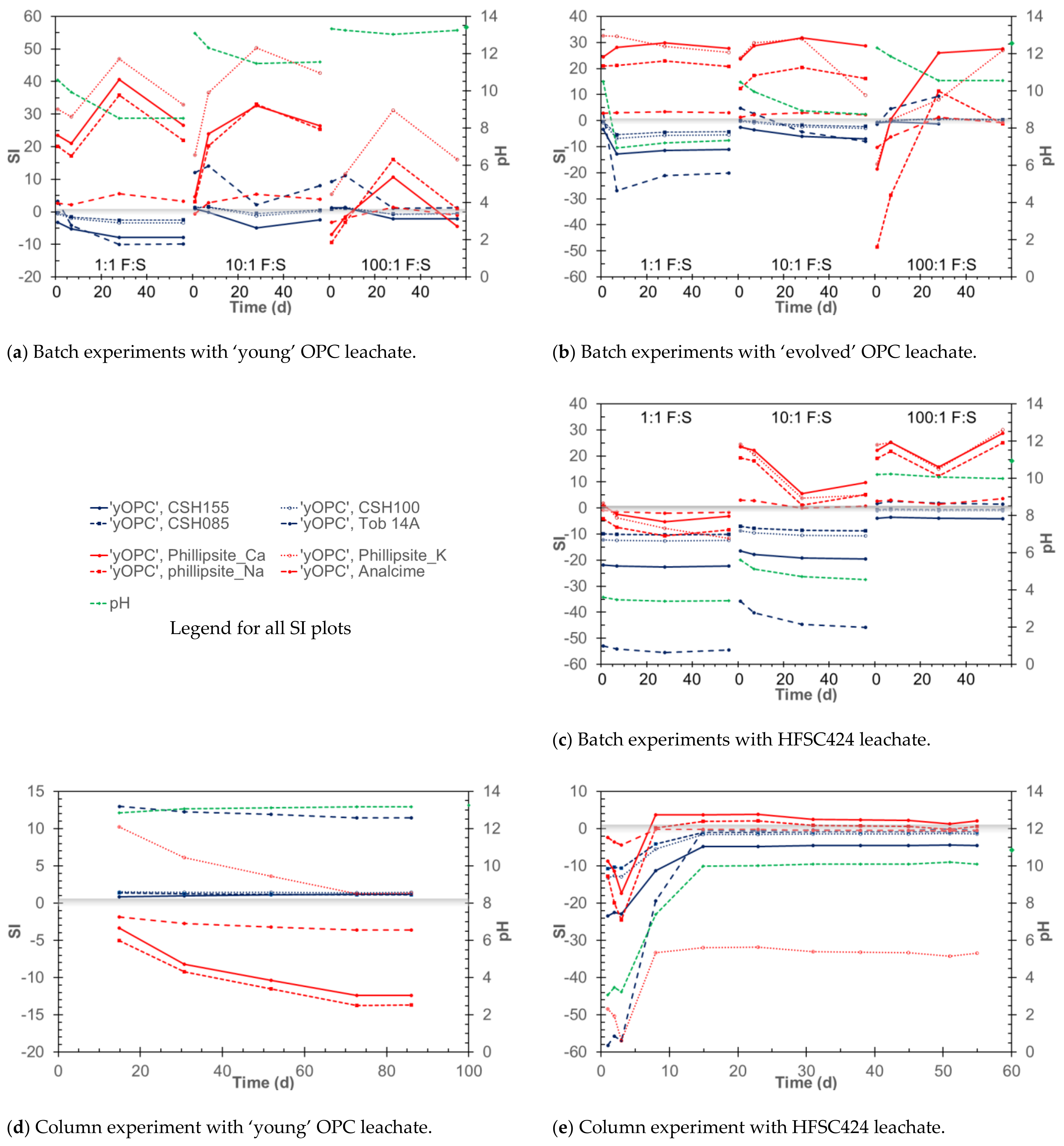
To examine the relationship between the reacted fluid chemistry and mineralogy, the PHREEQCv3 geochemical code [31] was used to calculate mineral saturation indices (SI) in the reacted fluids. This showed that in the 1:1 OPC leachate batch experiments, C-S-H phases were likely to be undersaturated, i.e., SI < 0 (Figure 7a), whereas in the higher F:S, OPC leachate batch experiments C–S–H phases were saturated (i.e., SI > 0). The SI calculations also suggested that zeolites (e.g., phillipsites and analcime) could be possible secondary phases (i.e., SI > 0) in these batch experiments (Figure 7a). The degree of saturation decreased with higher F:S ratios, and in some of the 100:1 F:S experiments, some zeolites, e.g., analcime, were undersaturated. However, no mineralogical evidence was found for the precipitation of zeolites. It is worth noting that a previous review of bentonite alteration by alkaline fluids [7] concluded that the available thermodynamic data for zeolites used in models tend to overestimate their stability.
In addition to C-S-H, M-S-H (magnesium silicate hydrate) have been identified in other studies [35,36,37] as potential products of cement-clay interactions (including LAC), though in some studies [15,18] they were only observed on the cement side of the interface and not within the mudstone. However, in the experiments conducted here, there was no mineralogical evidence found for their precipitation. The saturation state calculations suggested that only in the flow experiments with the ‘young’ OPC leachates were M-S-H phases saturated (Figure S3). In the batch experiments with all three fluids, only in the 100:1 F:S experiments (Figure S3) were some M-S-H phases found to be saturated.
In the flow experiments, the mineralogical observations showed that with the ‘young’ OPC leachates, there had been dissolution of the primary minerals and subsequent secondary C-(A-)S-H formation. The SI calculations for the reacted fluids (Figure 7d) indicated that, like the higher F:S OPC leachate batch experiments, C-S-H phases were likely to be saturated (i.e., SI > 0). However, unlike the batch experiments, most zeolites were undersaturated. In addition, the degree of undersaturation increased with time, i.e., number of pore volumes, which was a similar pattern to the batch experiments, where in the 100:1 F:S experiments, some zeolites were unsaturated (Figure 7a). The assessment of mineral saturation also showed that the primary mineral phases were slightly undersaturated, suggesting continued dissolution (i.e., SI < 0).
In the ‘evolved’ OPC batch experiments, the SI calculations suggested that as with the ‘young’ leachate, the C-S-H phases were undersaturated in the 1:1 experiments (i.e., SI < 0), but that as the F:S ratio (and pH) increased, they approached or exceeded saturation (i.e., SI > 0), and indeed C-S-H phases were observed in the higher F:S experiments (Figure 2b). Again, zeolites, although not observed, were predicted to be saturated in the 1:1 experiments, becoming less saturated with higher F:S ratios.
In the batch experiments with HFSC424 leachates, no mineralogical evidence was found for precipitation of any secondary phases. The saturation state calculations found that only in the reacted fluids from the 100:1 F:S experiments (Figure 7c) were some C-S-H phases close to saturation (i.e., SI > 0). In addition, zeolites were again identified as potential secondary phases in both the 10:1 and 100:1 experiments (Figure 7c), though unlike with the OPC leachate, zeolites were more saturated in the higher F:S experiments.
The saturation state calculations for the fluids from HFSC424 leachate flow experiments (Figure 7e), indicted that in the early fluids, like the 1:1 and 10:1 batch experiments, that C-S-H phases were undersaturated (i.e., SI < 0). In addition, as with the 100:1 batch experiments, in the later fluids some C-S-H phases were close to saturation (i.e., SI ~0) or even slightly saturated, which suggests that they could have precipitated, though no mineralogical evidence was found. Mass balance calculations for the precipitation of possible C-S-H phases, based on the difference in [Ca] between the incoming HFSC424 leachate and the reacted fluids, suggested that the maximum possible mass of C-S-H that could have formed would have been very low (i.e., Hillebrandite-type C-S-H < 0.01 g, Tobermorite 14Å-type < 0.02 g). The SI calculations also indicated that zeolites, as with the 1:1 batch experiments, were undersaturated (i.e., SI < 0). In the later fluids (Figure 7e), some zeolites, e.g., Ca-phillipsite, were slightly saturated, which was the same as the batch experiments (Figure 7c). Although no zeolites were seen in this study, other studies with LAC leachates [15] found that as well as C-S-H phases, zeolitic phases could also form in experiments with LAC leachates, but those studies [15] were conducted above ambient temperatures, which would have increased dissolution of the primary minerals, potentially leading to higher saturation states for both C-S-H and zeolitic phases. Primary mineral phases were undersaturated throughout, again suggesting continued dissolution.
4.3. Implications of Static vs. Dynamic Experiments
As can be seen by the comparison between the results of the batch and flow experiments, the 1:1 batch experiments are analogous to the initial conditions observed in flow experiments and thus representative of the early stage reactions. However, if the host rock contains a minor but highly reactive phase(s) that dominates early stage reaction but is not representative of the long-term evolution, as is the case with the Horonobe mudstone (i.e., dissolution of jarosite and/or gypsum), the low F:S batch experiments are liable to lead to unrealistic conclusions being drawn. In this case, the flow experiments give a better representation of the likely longer-term reactions, since transient reactions (i.e., initial changes in pH) are more easily identified. In addition, although the changes in [Na] and [K] suggested that ion exchange may have occurred in both batch and flow experiments, the higher concentrations of Na and K after ~20 d in the flow experiments suggest that it may only have a transient effect on the fluid chemistry.
The results from the fluid dominated, higher F:S ratio experiments were similar to the latter conditions seen in the flow experiments and give an indication of the longer-term evolution. However, as with the lower F:S batch experiments, there is the possibility of incorrect conclusions being drawn about the long term behavior if one of the species required for secondary phases formation is present only in one component (fluid or solid), and thus in the case of batch experiments it is finite. This is clearly illustrated in the higher F:S batch experiments with the ‘young’ OPC fluids, where extremely high concentrations of dissolved silica (Figure 3f) were present once the Ca from the original leachate was exhausted (Figure 3f).
The use of different configurations for flow experiments can also give better insight into the sequence of the reaction. In this study, the small flow cell (SFC) had advantages over the columns, for the fast reactive clay system evaluated here, in being able to better capture the spatial changes.
Batch reactors are well suited to long duration studies, being simpler and easier to maintain, and since they will tend towards equilibrium they are essential to the understanding of the long-term fluid–rock interactions. Flow experiments by introducing transport allows the investigation of the spatial and temporal extend of reactions, as well as being able to identify transient processes. In addition, they can be used to identify (key) components, which if constrained by availability, could influence the reaction sequence. Thus, the combination of static and dynamic approaches together with the linking of batch and flow data sets can provide an ideal mix of experimental methods with which to explore the long-term evolution of the alkaline fluid/mudstone system and identify key parameters and constraints. In addition, the configuration of the flow experiments, particularly in terms of length and sampling scale, needs to be appropriate to the (likely) reactivity of the experimental system under investigation. It is also recognized that laboratory experiments tend to yield faster reaction rates (due to use of crushed samples in the lab and the lower permeability, porosity, etc., in the field) compared to those observed in the field [38] and that allowance must be made for this when designing the experiments and extrapolating lab results to the field.
4.4. Implications for Spatial and Temporal Evolution
In terms of the spatial extent of the reactions, although there was evidence for continued dissolution of the primary minerals, i.e., trends in silica concentration, and the lack of fines in the reacted solids seen under SEM, the zone of precipitation in the flow experiments was limited to only the first few tens of millimeters in the case of the columns and ~3 mm for the SFC. Although the extent of the zone of precipitation was physically shorter in the SFC experiment compared to the column, comparison of the mass of Horonobe mudstone present in each set-up showed the actual extent of the reaction in each case to be similar. Section 1 of the column contained ~0.7 g of mudstone, whilst the first two sections of the SFC combined together contained ~0.6 g. One of the benefits of using dynamic flow experiments compared to the static batch experiments is in the determination of the extent of the zone of precipitation. In particular, the use of the SFC with its greater cross-sectional area and the ability to prepare thinner sliced samples is advantageous in this study, since it demonstrated that there was a slight delay before the precipitation of secondary phases, likely due to the need for silicate release from primary mineral dissolution and C-(A-)S-H nucleation.
Column experiments have been previously conducted [39], using samples of crushed smectite and OPA, to determine the extent of reaction using a similar simplified OPC leachate to this study, and although larger columns were used than those in this study, even after an 18-month duration the precipitation zone extended only ~20 mm into the OPA, where C-A-S-H phases were observed. The flow experiments presented here were of relatively short duration (<3 months) and were conducted at higher flow rates (potentially increasing the available Ca); nevertheless, the extent of the precipitation zone was similar, being observed only in the first sections (i.e., up to ~20 mm in the column, and ~3 mm with the SFC). The results of this study are also consistent with previous modelling and experimental studies on the extent of the reactions in argillaceous rocks [8,17,40], which all concluded that the zone of precipitation would be limited to only a few centimeters for in situ experiments and even more limited in the case of laboratory experiments [41]. Thus, the available data suggests that for mudstones, the extent of mineral precipitation is likely to be limited to the centimeter scale.
The experiments with the HFSC424 LAC leachates showed much less overall reaction compared to the OPC leachates, particularly in terms of the lack of observation of secondary phases.
There have been few other experimental studies [15,17,18,42] that have considered the impact of the use of LACs. The data available from this and these previous studies demonstrate that the primary objective of reducing pH and minimizing clay mineral dissolution can be achieved. However, some authors [17] have suggested that given the limited extent of reaction between OPC and argillaceous host rocks, the use of LACs is not necessary. Indeed, the use of OPC may favor secondary phase formation, especially that of C-S-H phases, which may then reduce transport of the leachates by reducing the permeability and porosity and so further limit the extent of CDZ. However, as well as changing the transport properties of the host rock, the secondary minerals formed by the reaction of OPC leachates with the host rock may also alter the sorption capacity with respect to radionuclides. Both C-S-H phases, and zeolites if present, may not exhibit an equally strong sorption capacity as the pristine host rock minerals, so reducing the potential for radionuclide retardation by sorption. In addition, sorption onto C-S-H can vary with Ca:Si ratio; for example, Cs sorbs well onto C-S-H phases with a low Ca:Si ratio [43]. This balance between reduced alteration and radionuclide migration may be an important consideration when deciding on the use or not of LACs. As well as influencing the radionuclide migration, the formation of secondary phases may limit access to the underlying reacting minerals by reducing the reactive surface area, since the secondary minerals will form a ‘skin’ on the primary mineral [17] but also by reducing the available porosity and permeability of the flowing system. The nature of this ‘skin’ of secondary minerals is not well characterized and will depend upon which secondary phases are precipitated, i.e., C-S-H and/or zeolites; the crystallinity of these secondary phases (for example C-S-H phases often initially form as gels becoming more crystalline with time [7]), which may affect fluid diffusion to the mineral surface; and also on the persistence of the skin, since the secondary phases formed may re-dissolve as the alkaline fluid chemistry evolves with time.
Flow experiments as used in this study can be useful here as the sequence of primary mineral dissolution, secondary mineral precipitation, and persistence can be directly observed. However, the experiments presented here employed crushed materials with high surface areas that will have enhanced the rate reaction and primary dissolution and are time limited.
5. Conclusions
In summary, both batch and flow-through experiments were conducted, reacting Horonobe mudstone with ordinary Portland cement (OPC) and low alkali cement (LAC) leachates to gain new insights into the reaction of host rock and such leachates. Typically, in the long term, pH decreased only slightly for all the leachates investigated. Major changes in the fluid chemistry were limited to a decrease in [Ca] due to precipitation of secondary C-(A-)S-H phases and the presence of dissolved silica from the continued dissolution of primary minerals.
The ‘young’ OPC leachate experiments showed the greatest reaction and alteration of the mudstone, but the zone of precipitation of C-(A-)S-H phases in the flow experiments was limited to only the first few tens of millimeters in the case of the columns, and ~3 mm for the small flow cell. Ion exchange reactions may have initially altered the fluid chemistry, but thereafter the reactions were dominated by primary mineral dissolution and the precipitation of secondary phases, particularly C-(A-)S-H.
It should be noted that unlike OPC there is no standard LAC composition, and that different compositions of LAC have been considered by different radioactive waste disposal implementers. It is also worth considering that disposal sites may have a combination of both OPC and LAC cements used for construction, so the effects of a mixed leachate or different spatially distributed leachates as well as different LAC compositions may need to be investigated and understood.
The results presented here demonstrate that a combination of both batch and flow-through experiments can provide the insights required for the understanding of the key geochemical interactions and the impact of transport, allowing the spatial as well as temporal evolution of the alkaline leachate/mudstone system to be successfully investigated. However, these experiments employed crushed materials, so the use of intact samples and in situ experiments with lower more realistic flow rates, together with data from monitoring boreholes in existing underground structures where cement and concretes have been deployed, is required to understand fully the spatial extent of the reactions to evaluate mineral evolution and the effect on radionuclide migration.
In addition, this research concentrated on the chemical and mineralogical effects within the mudstone and did not study the impact on the radionuclide migration, so further work with the altered mineral assemblage is required to determine the extent of the impact on the radionuclide behavior. The data from the experiments here can provide ‘test cases’ for the validation and calibration of reactive transport geochemical models, which can then be used to model the longer term evolution of the fluid rock interactions beyond what is possible experimentally. The experiments presented here suggest, together with other studies of argillaceous rocks, that in a mudstone, similar in composition to the Horonobe mudstone studied here, that the zone of greatest reaction in the CDZ is likely to be limited in extent, perhaps on the scale of centimeters.
Supplementary Materials
The following are available online at https://www.mdpi.com/article/10.3390/min11060588/s1, Figure S1: XRD analysis of mudstone samples from 10:1 F:S batch experiments with OPC leachates. Figure S2: XRD analysis of mudstone samples from SFC flow experiment with the ‘young’ OPC leachate. Figure S3 Indicative M-S-H saturation indices (SI) with time, together with pH.
Author Contributions
The individual contributions to this paper are as follows: Conceptualization and methodology, K.B., Y.A., and Y.T.; validation, K.B., M.K., and Y.O.; investigation and formal analysis, K.B., M.K., and Y.O.; resources, Y.T. and Y.A.; data curation, K.B. and Y.O.; writing—original draft preparation, K.B.; writing—review and editing, all authors. All authors have read and agreed to the published version of the manuscript.
Funding
This research received no external funding.
Data Availability Statement
The data used in this study is available from the authors upon request.
Acknowledgments
We thank Hikari Beppu and Takashi Endo for assistance with fluid chemical analysis. This study was supported by the JAEA Horonobe Underground Research Center, Hokkaido, Japan, providing the rock samples and background information.
Conflicts of Interest
The authors declare no conflict of interest.
References
- JNC. H12: Project to Establish the Scientific and Technical Basis for HLW Disposal in Japan, Project Overview Report and three Supporting Reports. JNC TN1410 2000–001~004; 2000. Available online: https://jopss.jaea.go.jp/pdfdata/JNC–TN1410–2000–003.pdf (accessed on 26 April 2021).
- Baker, A.J.; Bateman, K.; Hyslop, E.K.; Ilett, D.J.; Linklater, C.M.; Milodowski, A.E.; Noy, D.J.; Rochelle, C.A.; Tweed, C.J. Research on the alkaline disturbed zone resulting from cement–water–rock reactions around a cementitious repository. In NIREX REPORT N/054; UK Nirex Ltd.: Harwell, UK, 2002. [Google Scholar]
- JAEA. Second Progress Report on Research and Development for TRU Waste Disposal in Japan; Repository Design, Safety Assessment and Means of Implementation in the Generic Phase (TRU–2). JAEA–Review 2007–010, 2007/03; 2007. Available online: https://www.jaea.go.jp/04/be/documents/doc_02.html (accessed on 26 April 2021).
- Falck, W.E.; Nilsson, K.-F. Geological Disposal of Radioactive Waste–Moving Towards Implementation. In JRC Reference Reports, JRC45385 (EUR 23925 E); European Commission: Brussels, Belgium, 2009; Available online: http://ec.europa.eu/dgs/jrc/downloads/jrc_reference_report_2009_10_geol_disposal.pdf (accessed on 26 March 2021).
- Atkinson, A. The time dependence of pH within a repository for radioactive waste disposal. In UKAEA Report AERE–R 11777; UKAEA: Harwell, UK, 1985. [Google Scholar]
- Berner, U. Evolution of pore water chemistry during degradation of cement in a radioactive waste repository environment. Waste Manag. Nucl. Fuel Cycle 1992, 12, 201–219. [Google Scholar] [CrossRef]
- Savage, D.; Walker, C.S.; Arthur, R.C.; Rochelle, C.A.; Oda, C.; Takase, H. Alteration of bentonite by hyperalkaline fluids: A review of the role of secondary minerals. Phys. Chem. Earth 2007, 32, 287–297. [Google Scholar] [CrossRef]
- Savage, D. A review of analogues of alkaline alteration with regard to long–term barrier performance. Mineral. Mag. 2011, 75, 2401–2418. [Google Scholar] [CrossRef]
- Moyce, E.B.A.; Rochelle, C.A.; Morris, K.; Milodowski, A.E.; Chen, X.; Thornton, S.; Small, J.S.; Shaw, S. Rock alteration in alkaline cement waters over 15 years and its relevance to the geological disposal of nuclear waste. Appl. Geochem. 2014, 50, 91–105. [Google Scholar] [CrossRef] [Green Version]
- Bauer, A.; Berger, G. Kaolinite and smectite dissolution rate in high molar KOH solutions at 35 °C and 80 °C. Appl. Geochem. 1998, 13, 905–916. [Google Scholar] [CrossRef]
- Claret, F.; Bauer, A.; Schäfer, T.; Griffault, L.; Lanson, B. Experimental Investigation of the Interaction of Clays with High–pH Solutions: A Case Study from the Callovo–Oxfordian Formation, Meuse–Haute Marne Underground Laboratory (France). Clays Clay Miner. 2002, 50, 633–646. [Google Scholar] [CrossRef]
- Ramirez, S. Alteration of the Callovo–Oxfordian clay from Meuse–Haute Marne underground laboratory (France) by alkaline solution. I. A XRD and CEC study. Appl. Geochem. 2005, 20, 89–99. [Google Scholar] [CrossRef]
- Adler, M.; Mäder, U.K.; Waber, H.N. Core infiltration experiment investigating high pH alteration of low–permeability argillaceous rock at 30 °C. In Proceedings of the 10th International Symposium Water Rock Interaction (WRI–10), Villasimius, Italy, 10–15 July 2001; pp. 1299–1302. [Google Scholar]
- Pusch, R.; Zwahr, H.; Gerber, R.; Schomburg, J. Interaction of cement and smectitic clay–theory and practice. Appl. Clay Sci. 2003, 23, 203–210. [Google Scholar] [CrossRef]
- Lothenbach, B.; Bernard, E.; Mäder, U. Zeolite formation in the presence of cement hydrates and albite. Phys. Chem. Earth Parts A/B/C 2017, 99, 77–94. [Google Scholar] [CrossRef]
- Idiart, A.; Laviña, M.; Kosakowski, G.; Cochepin, B.; Meeussen, J.C.L.; Samper, J.; Mon, A.; Montoya, V.; Munier, I.; Poonoosamy, J.; et al. Reactive transport modelling of a low–pH concrete/clay interface. Appl. Geochem. 2020, 115, 104562. [Google Scholar] [CrossRef]
- Mäder, U.; Jeni, A.; Lerouge, C.; Gaboreau, S.; Miyoshi, S.; Kimura, Y.; Cloet, V.; Fukaya, M.; Claret, F.; Otake, T.; et al. 5-year chemico-physical evolution of concrete-claystone interfaces, Mont Terri rock laboratory (Switzerland). Swiss J. Geosci. 2017, 110, 307–327. [Google Scholar] [CrossRef] [Green Version]
- Dauzeres, A.; Le Bescop, P.; Sardini, P.; Cau Dit Coumes, C.; Brunet, F.; Bourbon, X.; Timonen, J.; Voutilainen, M.; Chomat, L.; Sardini, P. On the physico–chemical evolution of low–pH and CEM I cement pastes interacting with Callovo–Oxfordian pore water under its in situ CO2 partial pressure. Cem. Concr. Res. 2014, 58, 76–88. [Google Scholar] [CrossRef]
- Vehmas, T.; Maria Cruz Alonso, V.M.; Vašíček, R.; Rastrick, E.; Gaboreau, S.; Večerník, P.; Leivo, M.; Holt, E.; Fink, N.; Mouheb, N.A.; et al. Characterization of Cebama low–pH reference concrete and assessment of its alteration with representative waters in radioactive waste repositories. Appl. Geochem. 2020, 121, 104703, ISSN 0883-2927. [Google Scholar] [CrossRef]
- Iriya, K.; Matsui, A.; Mihara, M. Study on applicability of HFSC for radioactive waste repositories. In Proceedings of the 7th International Conference on Radioactive Waste Management and Environmental Radiation, Nagoya, Japan, 26–30 September 1999. [Google Scholar]
- Mihara, M.; Iriya, K.; Torii, K. Development of low–alkaline cement using pozzolans for geological disposal of long–lived radioactive waste. Doboku Gakkai Ronbunshuu F 2008, 64, 92–103. [Google Scholar] [CrossRef] [Green Version]
- Rochelle, C.A.; Milodowski, A.E.; Bateman, K.; Moyce, E.B.A. A long–term experimental study of the reactivity of basement rock with highly alkaline cement waters: Reactions over the first 15 months. Mineral. Mag. 2016, 80, 1089–1113. [Google Scholar] [CrossRef] [Green Version]
- Levenspiel, O. Chemical Reaction Engineering, 3rd ed.; Wiley: Hoboken, NJ, USA, 1998; ISBN 978-0-471-25424-9. [Google Scholar]
- Bateman, K.; Coombs, P.; Pearce, J.M.; Wetton, P.D. Nagra/Nirex/SKB Column Experiments; Fluid Chemical and Mineralogical Studies. In British Geological Survey Report WE/95/26; British Geological Survey: Nottingham, UK, 2001. [Google Scholar]
- Bateman, K.; Coombs, P.; Pearce, J.M.; Noy, D.J.; Wetton, P.D. Fluid Rock Interactions in the Disturbed Zone: Nagra/Nirex/SKB Column Experiments—Phase II. In British Geological Survey Report WE/99/5; British Geological Survey: Nottingham, UK, 2001. [Google Scholar]
- Small, J.S.; Byran, N.; Lloyd, J.R.; Milodowski, A.E.; Shaw, S.; Morris, K. Summary of the BIGRAD Project and Its Implications for a Geological Disposal Facility. In Report NNL; 2016; Volume 16, p. 13817. Available online: https://rwm.nda.gov.uk/publication/summary–of–the–bigrad–project–and–its–implications–for–a–geological–disposal–facility/ (accessed on 26 March 2021).
- Mazurek, M.; Eggenberger, U. Mineralogical analysis of core samples from the Horonobe area. In RWI Technical Report 05–01; Institute of Geological Sciences, University of Bern: Bern, Switzerland, 2005. [Google Scholar]
- Hiraga, N.; Ishii, E. Mineral and Chemical Composition of Rock Core and Surface Gas Composition in Horonobe Underground Research Laboratory Project (Phase 1). In JAEA Technical Report JAEA–Data/Code 2007–022; Japan Atomic Energy Agency, Tokai–Mura, Japan. 2008. Available online: https://jopss.jaea.go.jp/pdfdata/JAEA-Data-Code-2007-022.pdf (accessed on 16 May 2021).
- Savage, D.; Hughes, C.R.; Milodowski, A.E.; Bateman, K.; Pearce, J.; Rae, E.; Rochelle, C.A. The evaluation of chemical mass transfer in the disturbed zone of a deep geological disposal facility for radioactive wastes. I. Reaction of silicates with Calcium hydroxide fluids. In Nirex Report NSS/R244; UK Nirex Ltd: Harwell, UK, 1998. [Google Scholar]
- Savage, D.; Bateman, K.; Hill, P.; Hughes, C.R.; Milodowski, A.E.; Pearce, J.; Rochelle, C.A. The evaluation of chemical mass transfer in the disturbed zone of a deep geological disposal facility for radioactive wastes. II. Reaction of silicates with Na–K–Ca– hydroxide fluids. In Nirex Report NSS/R283; UK Nirex Ltd: Harwell, UK, 1998. [Google Scholar]
- Parkhurst, D.L.; Appelo, C.A.J. Description of Input and Examples for PHREEQC Version 3–A Computer Program for Speciation, Batch–Reaction, One–Dimensional Transport, and Inverse Geochemical Calculations. U.S. Geological Survey Techniques and Methods, Book 6, 2013, Chapter A43, p. 497. Available online: https://pubs.usgs.gov/tm/06/a43/ (accessed on 26 April 2021).
- JAEA. The Project for Validating Assessment Methodology in Geological Disposal System; Annual Report for JFY2016, JAEA Technical Report; Japan Atomic Energy Agency (JAEA): Ibaraki, Japan, 2017. (In Japanese) [Google Scholar]
- Mochizuki, A.; Ishii, E.; Miyakawa, K.; Sasamoto, H. Mudstone redox conditions at the Horonobe Underground Research Laboratory, Hokkaido, Japan: Effects of drift excavation. Eng. Geol. 2020, 267, 105496. [Google Scholar] [CrossRef]
- Berner, U.; Kulik, D.A.; Kosakowski, G. Influence of a low–pH cement liner on the near field of a repository for spent fuel and high–level radioactive waste. Phys. Chem. Earth 2013, 64, 46–56. [Google Scholar] [CrossRef]
- Bernard, E.; Lothenbach, L.; Cau–Dit–Coumes, C.; Chlique, C.; Dauzères, A.; Pochard, I. Magnesium and calcium silicate hydrates, part I: Investigation of the possible incorporation in calcium silicate hydrate (C–S–H) and of the calcium in magnesium silicate hydrate (M–S–H). Appl. Geochem. 2018, 89, 229–242. [Google Scholar] [CrossRef]
- Bernard, E.; Lothenbach, B.; Chlique, C.; Wyrzykowski, M.; Dauzères, A.; Pochard, I. Cau–Dit–Coumes, C. Characterization of magnesium silicate hydrate (M–S–H). Cem. Concr. Res. 2019, 116, 309–330. [Google Scholar] [CrossRef]
- Bernard, E.; Jenni, A.; Fisch, M.; Grolimund, D.; Mäder, U. Micro–X–ray diffraction and chemical mapping of aged interfaces between cement pastes and Opalinus Clay. Appl. Geochem. 2020, 115, 104538. [Google Scholar] [CrossRef]
- White, A.F.; Brantley, S.L. The effect of time on the weathering of silicate minerals: Why do weathering rates differ in the laboratory and field? Chem. Geol. 2003, 202, 479–506. [Google Scholar] [CrossRef]
- Taubald, H.; Bauer, A.; Schafer, T.; Geckeis, H.; Satir, M.; Kim, J.I. Experimental investigation of the effect of high–pH solutions on the Opalinus Shale and the Hammerschmiede Smectite. Clay Miner. 2000, 35, 515–524. [Google Scholar] [CrossRef]
- Torres, E.; Turrero, M.J.; Escribano, A.; Martín, P.L. Geochemical Interactions at the Concrete–Bentonite Interface of Column Experiments. Long–Term Performance of Engineered Barrier Systems PEBS: DELIVERABLE (D–N°: D2.3–6–1). 2013. Available online: https://www.pebs–eu.de/PEBS/EN/Downloads/D2_3_6_1.pdf?__blob=publicationFile&v=2 (accessed on 17 March 2021).
- Shafizadeh, A.; Gimmi, T.; Van Loon, L.R.; Kaestner, A.P.; Mäder, U.K.; Churakov, S.V. Time–resolved porosity changes at cement–clay interfaces derived from neutron imaging. Cem. Concr. Res. 2020, 127, 105924. [Google Scholar] [CrossRef]
- Huertas, F.; Farias, J.; Griffault, L.; Leguey, S.; Cuevas, J.; Ramirez, S.; Vigil de la Villa, R.; Cobeňa, J.; Andrade, C.; Alonso, M.C.; et al. Effects of Cement of Clay Barrier Performance, ECOCLAY project: Final Report; Report EU 19609; European Commission: Brussels, Belgium, 2000. [Google Scholar]
- Missana, T.; García–Gutiérrez, M.; Mingarro, M.; Alonso, U. Comparison between caesium and sodium retention on calcium silicate hydrate (CSH) phases. Appl. Geochem. 2018, 98, 36–44, ISSN 0883-2927. [Google Scholar] [CrossRef]
Figure 1.
Schematic of flow set-up, with inset detail of small flow cell (SFC). Note: ‘O-rings’, porous disks, and filters were fitted to both sides of the SFC.
Figure 1.
Schematic of flow set-up, with inset detail of small flow cell (SFC). Note: ‘O-rings’, porous disks, and filters were fitted to both sides of the SFC.

Figure 2.
Changes in fluid chemistry with time. (a) pH batch and flow experiments; (b) [Na] batch and flow experiments; (c) [K] batch and flow experiments; (d) [Ca] batch experiments; (e) [Ca] and [SiO2] flow experiments; (f) [SiO2] batch experiments (inset shows ‘young’ OPC 10:1 data). Diamonds on the vertical axis indicate initial leachate concentrations. In the graphs where both batch and flow data are shown together (a–c), the single points indicate data from batch experiments, and the lines the flow experiments. Legend text: yOPC—‘young’ OPC leachate; eOPC—‘evolved’ OPC leachate; HFSC—HFSC424 leachate. For batch experiments, the F:S is indicated.

Figure 3.
Secondary electron (SE) image and SEM-EDS analysis of reacted mudstone. Batch experiment 10:1 F:S with the ‘evolved’ OPC leachate. The white squares (a–c) in the SEM image indicate areas used for SEM-EDS analysis, and the corresponding figures (a–c) show the presence of primary minerals (a) and secondary C-S-H (b,c).

Figure 4.
Summary of mineralogy, column experiment with the ‘young’ OPC leachate. Arrows indicate direction of flow; numerals refer to Section numbers; each Section (apart from Sections 1 and 19) ~15 mm long. All SEM photos are secondary electron (SE) images. White squares (a,b) in the SEM image from Section 1 indicate areas used for SEM-EDS analysis of C(A)-S-H phases.

Figure 5.
Summary of mineralogy, SFC experiment with the ‘young’ OPC leachate. Arrow indicates direction of flow; numerals refer to Section numbers. Each section was ~1.5 mm long. All SEM photos are secondary electron (SE) images. The white square in the SEM image from Section 2 indicates the area used for SEM-EDS analysis of C(A)-S-H phases.

Figure 6.
Summary of mineralogy, SFC experiment with the HFSC424 leachate. Arrow indicates direction of flow; numerals refer to Section numbers. Each section was ~2.5 mm long. All SEM photos are secondary electron (SE) images.
Figure 6.
Summary of mineralogy, SFC experiment with the HFSC424 leachate. Arrow indicates direction of flow; numerals refer to Section numbers. Each section was ~2.5 mm long. All SEM photos are secondary electron (SE) images.

Figure 7.
Indicative C-S-H and zeolite mineral saturation indices (SI) with time, together with pH. (a) Batch experiments with ‘young’ OPC leachate. (b) Batch experiments with ‘evolved’ OPC leachate. (c) Batch experiments with HFSC424 leachate. (d) Column experiment with ‘young’ OPC leachate. (e) Column experiment with HFSC424 leachate. Batch experiments are plotted from low to high F:S ratio for comparison with the flow experiments (C-S-H in blue, zeolites in red, pH in green). Shaded grey line indicates equilibrium state, i.e., SI = 0; below this line minerals will tend to dissolve, and above it they may precipitate.


Table 1.
Initial concentrations of ions in the fluids used for the experiments.
| Leachate Type | Components (mg/L) | ||||||
|---|---|---|---|---|---|---|---|
| pH at 24 °C | Na | K | Ca | SiO2 | Cl– | SO42– | |
| ‘young’ OPC leachate (Na-K-Ca-OH) | 13.4 | 1500 | 7300 | 60 | – | – | – |
| ‘evolved’ OPC leachate (saturated Ca(OH)2) | 12.5 | 800 | – | – | – | ||
| HFSC424 leachate | 11 | 3300 | 1330 | 94 | 370 | 3300 | 760 |
| Horonobe ground water, borehole 07-V140-M03 | 7.9 | 2960 | 160 | 80 | – | 3400 | 585 |
Table 2.
Comparison of the physical parameters for the different flow equipment.
| Column | Small Flow Cell (SFC) | |
|---|---|---|
| Total mudstone weight (g) | 10.3 | 3.14 |
| Length (mm) | 300 | 10 |
| Cross-sectional area (mm2) | 44 | 314 |
| Volumetric flow rate (mL/h) | ~0.5 | ~0.5 |
| Residence time (h) | ~15 | ~3.5 |
Publisher’s Note: MDPI stays neutral with regard to jurisdictional claims in published maps and institutional affiliations. |
© 2021 by the authors. Licensee MDPI, Basel, Switzerland. This article is an open access article distributed under the terms and conditions of the Creative Commons Attribution (CC BY) license (https://creativecommons.org/licenses/by/4.0/).
Share and Cite
MDPI and ACS Style
Bateman, K.; Amano, Y.; Kubota, M.; Ohuchi, Y.; Tachi, Y. Reaction and Alteration of Mudstone with Ordinary Portland Cement and Low Alkali Cement Pore Fluids. Minerals 2021, 11, 588. https://doi.org/10.3390/min11060588
AMA Style
Bateman K, Amano Y, Kubota M, Ohuchi Y, Tachi Y. Reaction and Alteration of Mudstone with Ordinary Portland Cement and Low Alkali Cement Pore Fluids. Minerals. 2021; 11(6):588. https://doi.org/10.3390/min11060588
Chicago/Turabian StyleBateman, Keith, Yuki Amano, Mitsuru Kubota, Yuji Ohuchi, and Yukio Tachi. 2021. "Reaction and Alteration of Mudstone with Ordinary Portland Cement and Low Alkali Cement Pore Fluids" Minerals 11, no. 6: 588. https://doi.org/10.3390/min11060588
Note that from the first issue of 2016, this journal uses article numbers instead of page numbers. See further details here.