On-Chip Tunable Cell Rotation Using Acoustically Oscillating Asymmetrical Microstructures


1
School of Mechanical Engineering & Automation, Beihang University, Beijing 100191, China
2
Beijing Advanced Innovation Center for Biomedical Engineering, Beihang University, Beijing 100083, China
3
Department of Micro-Nano Mechanical Science & Engineering, Nagoya University, Nagoya 464-0814, Japan
*
Author to whom correspondence should be addressed.
†
These authors contributed equally to this work.
Micromachines 2018, 9(11), 596; https://doi.org/10.3390/mi9110596
Submission received: 26 September 2018
/
Revised: 31 October 2018
/
Accepted: 8 November 2018
/
Published: 14 November 2018
Abstract
:The precise rotational manipulation of cells and other micrometer-sized biological samples is critical to many applications in biology, medicine, and agriculture. We describe an acoustic-based, on-chip manipulation method that can achieve tunable cell rotation. In an acoustic field formed by the vibration of a piezoelectric transducer, acoustic streaming was generated using a specially designed, oscillating asymmetrical sidewall shape. We also studied the nature of acoustic streaming generation by numerical simulations, and our simulation results matched well with the experimental results. Trapping and rotation of diatom cells and swine oocytes were coupled using oscillating asymmetrical microstructures with different vibration modes. Finally, we investigated the relationship between the driving voltage and the speed of cell rotation, showing that the rotational rate achieved could be as large as approximately 1800 rpm. Using our device, the rotation rate can be effectively tuned on demand for single-cell studies. Our acoustofluidic cell rotation approach is simple, compact, non-contact, and biocompatible, permitting rotation irrespective of the optical, magnetic, or electrical properties of the specimen under investigation.
1. Introduction
Cell manipulations have attracted great attention in the field of modern bioscience [1,2] because the cell is the basic structural, functional, and biological unit of all known living organisms. Cell rotation is one of the fundamental techniques of cell manipulations, which plays a key role in various fields, including cell observation [3], cell analysis [4,5,6], and drug discovery [7]. For example, diatom cells can be set in an ordered alignment by specific rotational manipulation, which is utilized to achieve detection in screening, diagnosis, and medicine. In addition, since spindle observation is very important during meiosis to study its dynamic behavior and obtain other information, it should be oriented to a specific angle via cell rotation for observation under a polarization microscope [8]. Furthermore, controllable cell rotation is also required for the removal or the transfer of nuclei in transgenic animal research [9,10]. For instance, after enucleation by chemical treatment, an observation via high-speed cell rotation must be performed to confirm whether the nuclei of cells have been removed successfully, because the nucleus of an oocyte is anisotropically located at the cell edge, which is not visible in typical translational manipulations. Thus, cell rotation has become a powerful tool for cell observation.
Different approaches have been adopted to achieve rotational manipulation of microparticles and cells. Conventionally, two micromanipulators are used to perform motions. Under a microscope, one micromanipulator immobilizes the target cell, while the other applies a torque for the rotation [11,12]. However, this operation requires expert operators, which reduces its applicability and repeatability. Lin Feng et al. succeeded in cell rotation using dual-arm magnetically driven microtools, but this technique requires a complex control system [13]. Although optical tweezers have been successfully used to rotate cells, damage to the biological samples by laser-induced heating may be observed, and a sufficiently strong torque to rotate larger cells (>20 μm) may not be generated [14,15]. In the electrorotation technique, an electric field is applied to induce a torque to the target cell by patterning multiple electrodes [16,17,18]. Nevertheless, these custom-designed electrode structures are rather complex to fabricate, and this approach may destroy biological species by current-induced heating. However, as of yet, no detailed research has been performed on high-speed rotational manipulation of big-size cells like swine oocytes.
Acoustic waves have recently offered a promising alternative technique for force generation at the microscale level and have been widely employed for several applications [19,20,21]. Acoustofluidic devices that fuse acoustics and microfluidics have the potential to dramatically improve methods for manipulating cells and small biological samples. For example, an oscillating solid structure placed in a microfluidic environment generates a local acoustic flow [22,23,24]. Ozcelik et al. used vibrating sharp-edged microstructures to engender two counter-rotating microvortices in the surrounding fluid [25]. However, this acoustofluidic device merely achieved the rotational manipulation of HeLa cell (≈20 μm) using oscillating solid structures and was unable to perform the rotation of big-size cells like oocytes (>80 μm). Hayakawa et al. adopted micropillar patterns to accomplish the rotation of mouse oocytes based on a vibration-induced whirling flow [26,27]. Nonetheless, the target cells were not retrieved from the microchip, and the flexibility in adjusting the rotational speed was hard to control. Ahmed et al. trapped air microbubbles within predefined sidewall microcavities inside a microchannel utilized to rotate cells. A drawback of the microbubbles is their enlargement over time, which eventually shifts their resonance frequency [28,29].
Thus, we, herein, aim to create adequately robust, stable, and controllable forces to manipulate the high-speed rotation of big-size cells (≈100 μm) by designing custom-made structures. We propose an on-chip cell rotation technology using acoustic waves, which integrates the rotation mechanisms of ultrasonic vibration into a microfluidic chip. Compared with other technologies, this method is robust, biocompatible, easy to control, and independent of the optical, magnetic, or electrical properties of the sample. It allows an effective and precise rotation of specimens over a wide range of sizes, shapes, and properties.
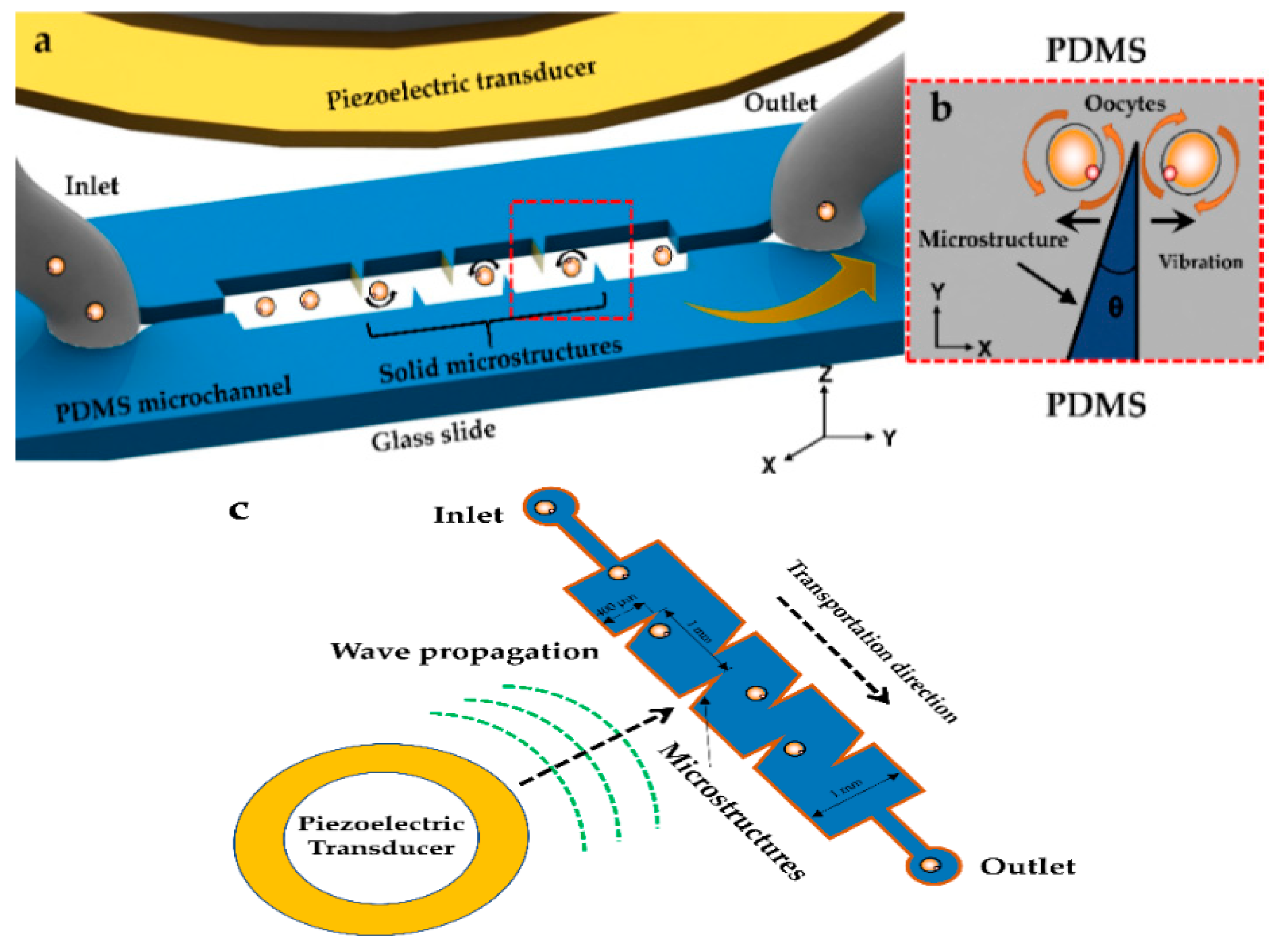
Figure 1a shows the design of the microfluidic chip driven by acoustic flows, including a polydimethylsiloxane (PDMS) microchannel with six microstructures and a piezoelectric transducer that provides the acoustic energy. Inlet and outlet holes were punched into the PDMS chip and used to load and unload cells. The length, width, and depth of the microchannel were 5 mm, 1 mm, and 200 μm, respectively (Figure 1c). Considering the diameter of our experimental samples and previous researches performed by Adem Ozcelik’s group [25], each microstructure was designed to be of a constant length of 400 μm, a tip angle (θ) of 20°, and a depth of 200 μm, which was used to generate acoustic streaming for cell rotation (Figure 1b). The piezoelectric transducer and the microfluidic chip were bonded on a glass slide (150 μm). Our experimental objects were diatom cells (≈80 μm) and swine oocytes (≈100 μm). Figure 1c also illustrates that, when acoustic waves are excited by a piezoelectric transducer, vibration-induced local acoustic flows are generated in the surrounding fluid because of viscous dissipation in the microchannel. Moreover, the response to time-harmonic forcing is generally not harmonic because of the dissipative property of the fluid. The fluid’s response to harmonic forcing can be viewed as a combination of a time-harmonic response, generally referred to as acoustic response, and the remainder, referred to as acoustic streaming. The latter is a byproduct of the acoustic attenuation caused by viscous dissipation; hence, it provides a unique method of utilizing the dominant viscous nature of microfluidic flows [30,31,32,33]. With the growing use of cell-on-chip tools for investigating microparticles and cells, our method is anticipated to be an invaluable tool in biology, biophysics, and medicine.
2. Materials and Methods
2.1. Theoretical Analysis
Numerical simulations were performed to theoretically analyze the mechanisms and properties of acoustic streaming generation [32,33]. Vectors and scalars are represented by bold and regular fonts, respectively. First, the continuity and momentum equations are as follows:
where ρ is the mass density, v is the velocity of fluid, p is the pressure of fluid, and and are bulk and shear dynamic viscosities, respectively. The relation between ρ and p was assumed to be linear:
where c0 is the velocity of sound in the fluid at rest. We employed Nyborg’s perturbation technique [34] and expanded the field of fluid velocity, density, and pressure as follows:
where ρ0 is the density of the fluid at rest and a constant, v1 is the first-order sound velocity, and ρ2 and v2 are the second-order parameters. Substituting Equations (3) and (4) into Equations (1) and (2), respectively, the following equations, referred to as the first- and second-order equations of acoustics, are obtained:
and
where denotes the time average of quantity x over a full oscillation time period. As pointed out in Equations (5)–(8), the time averages of the continuity and momentum equations were not zero, indicating the streaming velocity of the fluid. Moreover, note that these equations, which were complemented with appropriate boundary conditions, were numerically solved using the commercial finite element method ANSYS FLUENT 17.0 (Canonsburg, PA, USA) to characterize the acoustic streaming distributions in the vicinity of the microstructures. Further details would be discussed in the subsequent part. Consequently, the real mechanism of formation of acoustic streaming is caused by viscous dissipation and non-linear absorption in the microchannel.
2.2. Simulation and Observed Trajectories
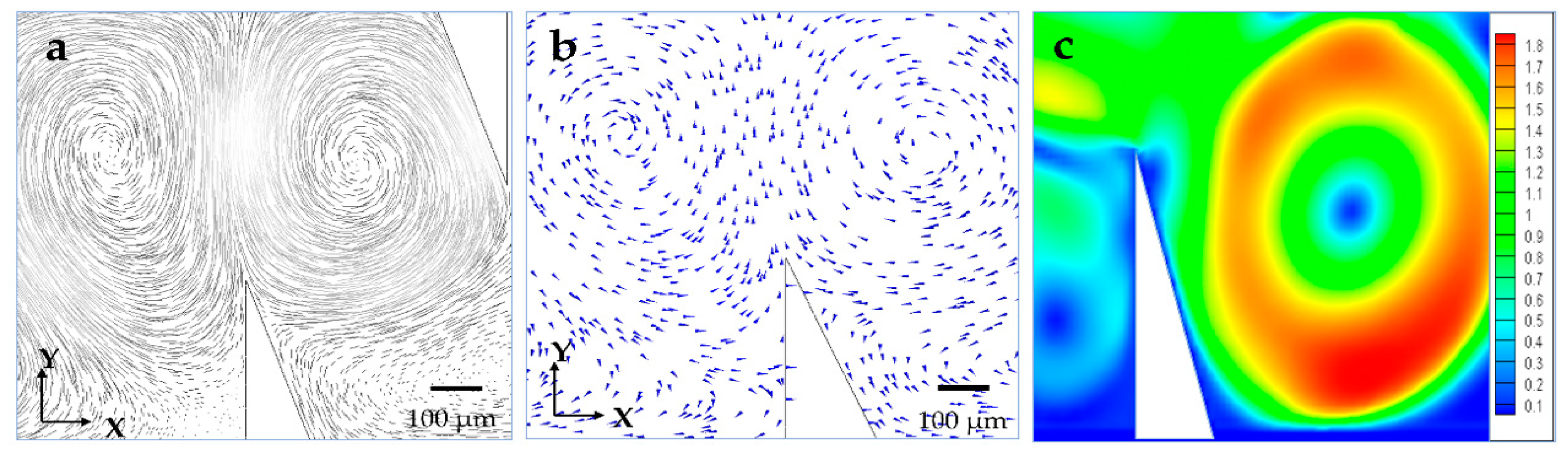
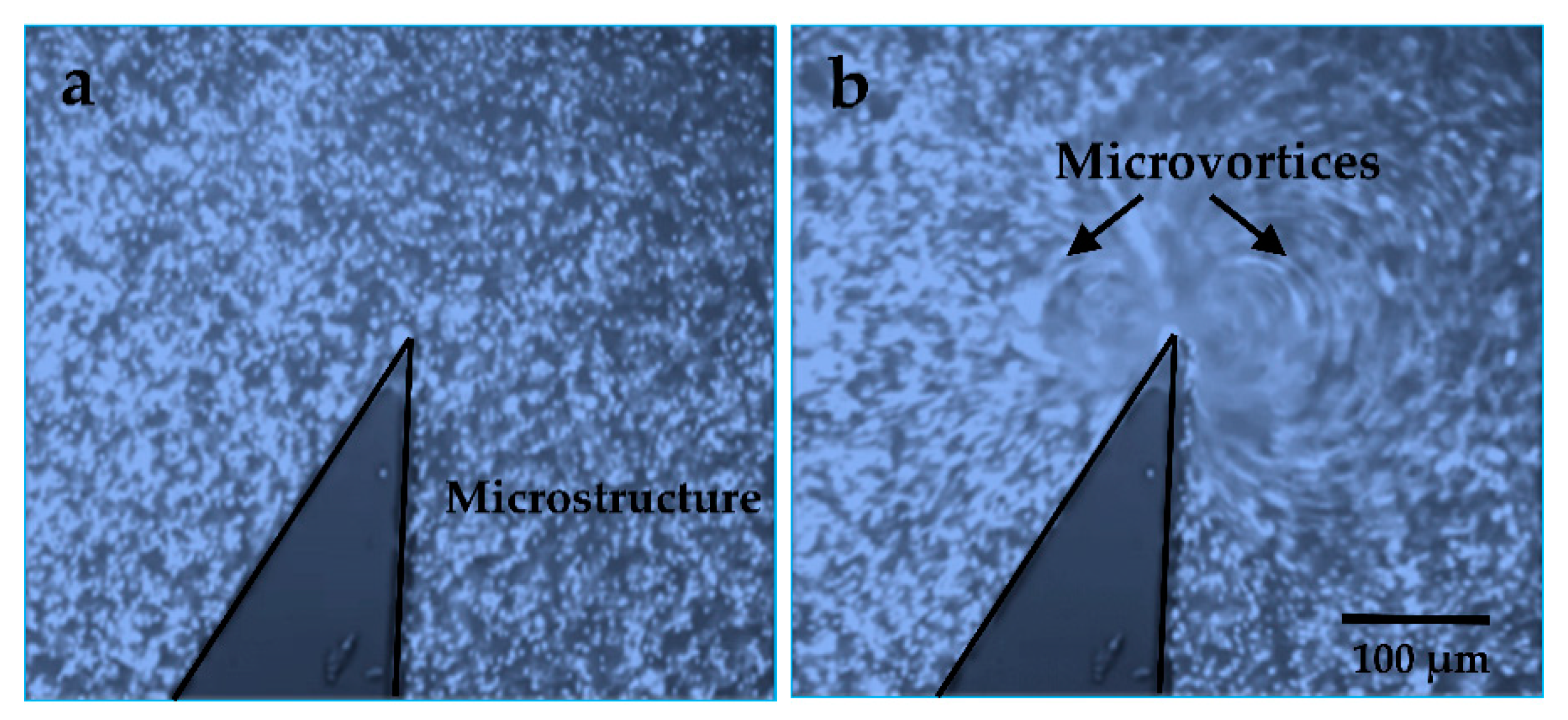
Finite element method (FEM) simulations for modeling the local microstreaming in the presence of microstructures are used to confirm this unique phenomenon under the standing acoustic wave. Figure 2a–c show the simulation results of the oscillating solid microstructure at 4.6 kHz using ANSYS FLUENT 17.0, (type of mesh used: all triangles method, mesh size: 10 μm, boundary conditions: outflow). With this method, two counter-rotating microvortices were generated by setting up the oscillation function in the X–Y plane, which matched well with our previous numerical analysis. Accordingly, 1 μm diameter fluorescent polystyrene spherical beads (PSRF01000, ZHONGKELEIMING Co., Ltd., Beijing, China) were subjected to the experimental system to confirm the fluid field distribution around the solid microstructures (10 µL of the particle suspension was centrifuged and washed with deionized water three times. Then, the microsphere suspensions were diluted to 100 µL using deionized water). Figure 3a,b show that a vibrating solid structure induced two local acoustic flows in its vicinity when a sine wave was applied, and the driven oscillation was harmonic with a frequency equal to 4.6 kHz (Video S1, Supplementary Materials). Moreover, the size of the microvortices on both sides of the solid microstructure was different because of the asymmetric design, which was utilized to perform different manipulations in a low-power acoustic field in the following experiments.
3. Experiments and Results
3.1. System Setup
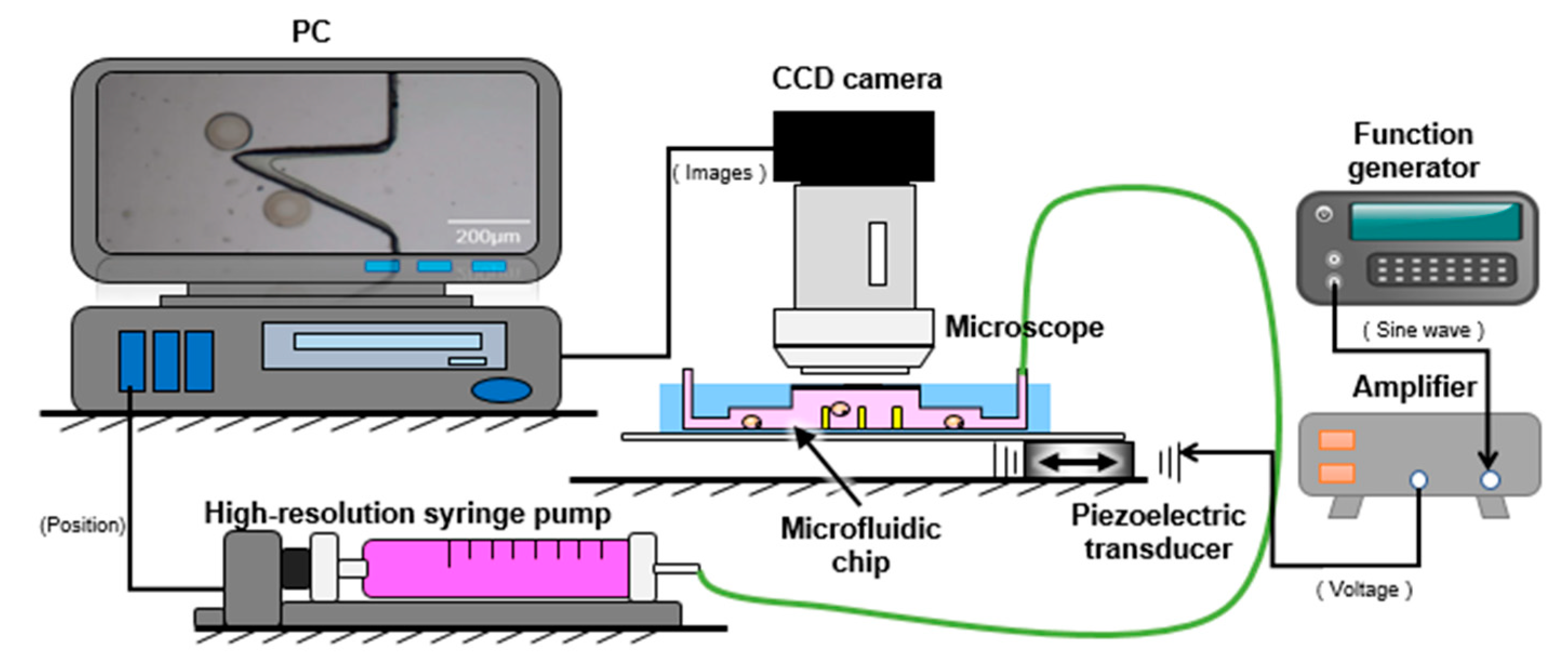
Figure 4 shows an overview of the system components of the manipulation platform, consisting of the observation and driving systems. A charge-coupled device (CCD) camera (GS3-U3-23S6C-C, Point Grey Co., Ltd., Richmond, BC, Canada) was attached to a differential interference contrast (DIC) microscope (CX41, Olympus Co., Ltd., Tokyo, Japan) to observe the manipulation better. A control personal computer was used to acquire real-time and stereoscopic images. The microfluidic chip was fixed on a stage. The other system included three parts. A function generator (Wave Station 2012, LECROY, New York, NY, USA) sent a sine wave to a high-voltage amplifier (ATA-2042, Agitek, Xi’an, China). This output signal was then used to drive the piezoelectric transducer. Meanwhile, a high-resolution syringe pump (PHD ULTRA NANOMITE, Harvard, Cambridge, MA, USA) was applied to the inlet of the PDMS channel, which could inject micro and quantitative liquid to transport cells steadily and accurately.
Figure 5a shows the fabrication process of the microfluidic chip. First, the photoresist SU-8 (GM1075, Resemi, Suzhou, China) was coated on the substrate at 1000 rpm for 90 s. The SU-8 mold was developed after exposure (see Figure 5b). A Sylgard 184 silicone elastomer base was mixed with Sylgard 184 silicone elastomer curing agent (Dow Corning, Midland, MI, USA) at a ratio of 10:1 and cured at 70 °C for 2 h to form the PDMS channels. Subsequently, the surface of the PDMS channels and a 40 mm × 50 mm × 0.15 mm (width × length × thickness) glass slide were treated with oxygen plasma for 20 s and bonded at 90 °C for 10 min. Finally, a piezoelectric transducer (81-7BB-27-4L0, Murata Electronics, Kyoto, Japan) was attached on the back of the glass and adjacent to the PDMS channels using epoxy (84101, Permatex, Hartford, CT, USA).
3.2. Rotational Manipulation
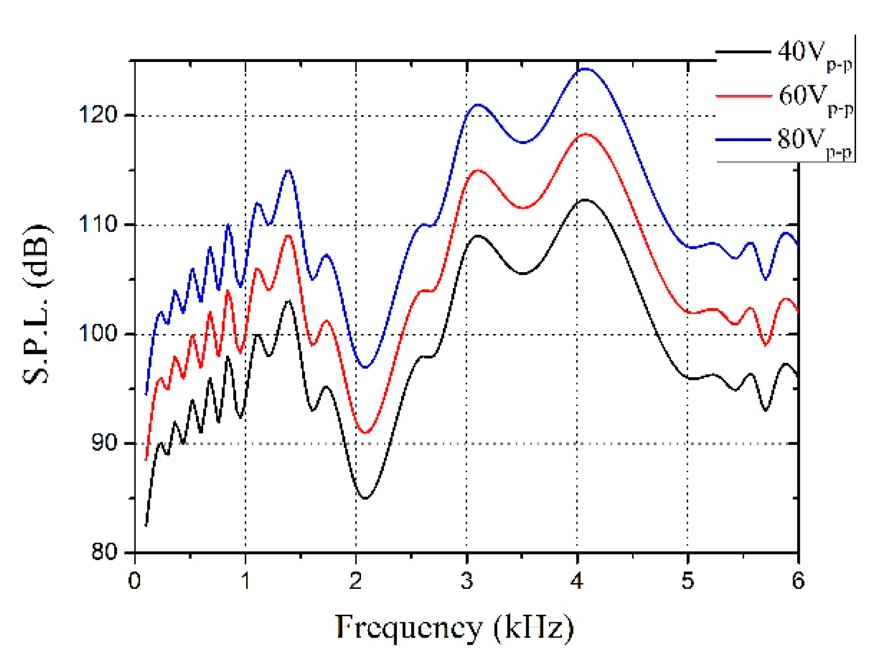
In Figure 6, the sound pressure level (S.P.L.) was different because the vibration amplitude of the piezoelectric transducer varied with changes of the driving frequency, which illustrated that the S.P.L. was closely related to acoustic energy. The piezoelectric transducer was driven by applying the voltage; hence, the S.P.L. increased upon increasing the voltage within limits (Figure 6). Therefore, 20 Vp-p sine wave voltage was applied on the piezo, and the frequency in high S.P.L. was selected to conduct experiments on evident experimental phenomena.
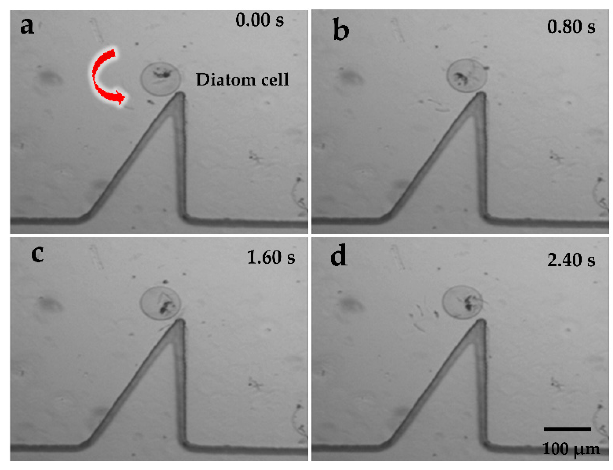
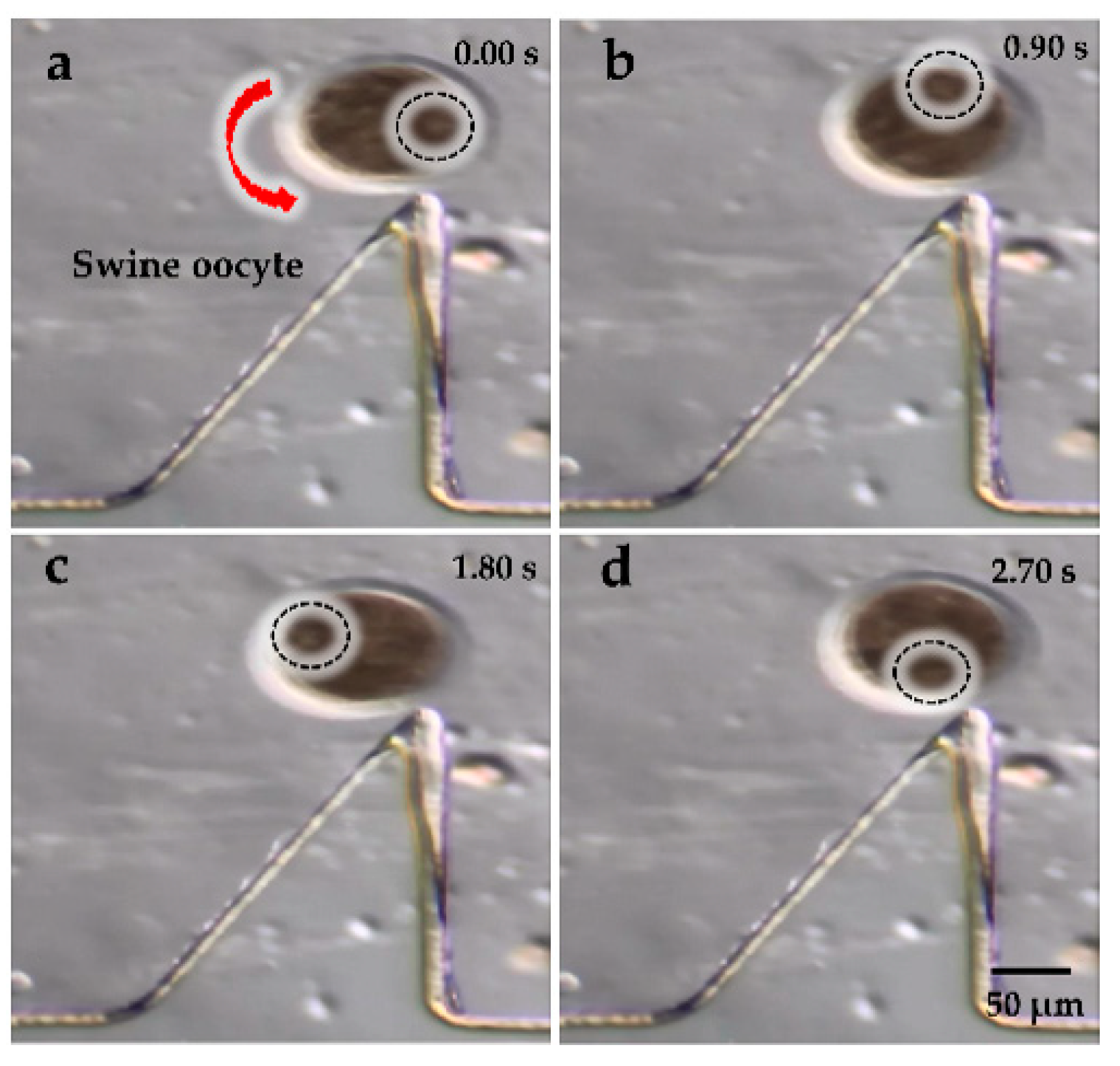
Figure 7a–d and Figure 8a–d show the rotational manipulation of the diatom cell and the swine oocyte, respectively (Video S1, Supplementary Materials). At the tip of the oscillating solid microstructure, a strong torque was created at 4.6 kHz and 20 Vp-p (peak-to-peak voltage value), which was used to achieve cell rotation. Considering different sizes of the swine oocyte and the diatom cell, the rotational speed is well-known to decrease upon increasing the cell diameter in the same driving voltage. In addition, when the applied frequency was changed to 4.2 kHz, the microstreaming orientation was switched to a clockwise direction (Video S1, Supplementary Materials). Qiang Tang et al. investigated patterns of the acoustic streaming field at different frequencies and proved that, as the frequency increased, the vibrating pattern became more complex, which could result in different orientations of the acoustic streaming field [35]. Such behavior is attributed to the change of the vibrating pattern. At different applied frequencies, the oscillating microstructure provides different types of acoustic wave patterns because the acoustic streaming structure is strongly influenced by the vibration source which provided acoustic energy. Consequently, the location of the exciting source and corresponding boundaries will change according to previous researches [36,37], leading to localized reversed direction of the acoustic streaming vortex.
We also examined the relationship between the diatom cell rotational speed and the driving voltage. The voltage was adjusted by 10 Vp-p every time from 20 to 80 Vp-p, using an amplifier at 4.6 kHz. The tip angle, channel width, and depth were experimentally optimized to 20°, 1000, and 200 μm, respectively. Figure 9 illustrates that the rotational speed of the diatom cells increased with the increasing voltage, which could be as large as, approximately, 1800 rpm. The flexibility of the rotational speed supports its wide utilization in single-cell studies, where the shear force for the rotation can be tuned on-demand. In a micro/nanometer-size world, the viscous force and other surface forces exert a dominant impact on cell manipulation, while the volume and inertia forces hardly have any effect. Therefore, the cells rarely maintain the rotation when the supply is cut off because of the strong viscosity, which could easily control the specific cell position and orientation (Video S1, Supplementary Materials).
Finally, we needed to assess the effect of the proposed method driven by acoustic waves on the viability of cells. On the basis of previous experiments by our group, we transported and rotated five oocytes with our combined system for five minutes. The target oocytes were collected and incubated in a culture well at 37 °C in a 5% CO2 atmosphere for three hours. The viability of the incubated cells was then assessed using the LIVE/DEAD Viability Kit (L-3224, Life Technologies Japan Ltd., Tokyo, Japan). All experimental samples remained viable after the incubation. Thus, the proposed method did not affect cell viability [26].
3.3. Cell Trapping
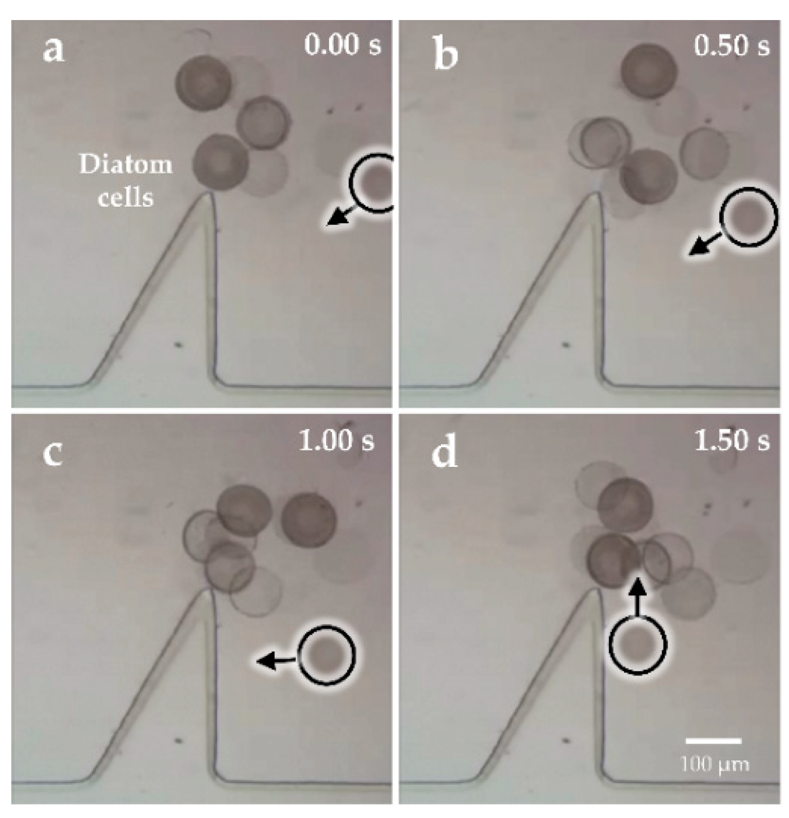
Figure 10 shows cell trapping during the transportation by adjusting different frequencies, which effectively settled the problem about transporting the cell to a certain position with high precision (Video S1, Supplementary Materials). The cell was trapped in a special trajectory driven by acoustic flows when we applied a vibration with the frequency of 4 kHz at the voltage of 40 Vp-p. Especially, the right-side structure was able to form stronger acoustic streaming than the other side, which was utilized to trap cells in a lower voltage. Figure 11 shows that the time required for successfully trapping a cell at a distance of 400 μm was only approximately 1.5 s and would continue to reduce with the increasing driving voltage.
4. Conclusions
This study describes a rotational manipulation method using acoustic waves in a microfluidic chip. We also successfully demonstrated the feasibility of non-invasive and non-contaminated trapping and rotation of diatom cells and swine oocytes at different vibration modes. The torque created by a specially designed oscillating microchannel shape with triangles was controlled by adjusting the voltage applied to the piezoelectric transducer, which can be used for various applications by choosing the required rotational speeds. Our future work will be focused on achieving a three-dimension rotation of oocytes with increased precision and motion stability.
Supplementary Materials
The following are available online at https://www.mdpi.com/2072-666X/9/11/596/s1, Video S1: Cell manipulation.
Author Contributions
L.F. and B.S. equally contributed to this work. L.F., B.S., and Y.J. conceived and designed the experiments; B.S. performed the experiments; L.F., D.Z., and F.A. analyzed the data; L.F., Y.J., and D.Z. contributed reagents/materials/analysis tools; L.F. and B.S. wrote the paper.
Funding
This research received no external funding.
Acknowledgments
The authors would like to thank Xiaoxiang Hu, Xiaojuan Liu, and Yuexin Lin (Department of Biological Sciences, China Agricultural University, Beijing, China) for their help with swine oocytes preparation. The authors gratefully acknowledge the support in diatom cells experiments from Jun Cai and Zhenghu Wang (Department of Mechanical Engineering and Automation, Beihang University, Beijing, China). This work was supported by the Natural Science Foundation of Beijing (Grant No. 17L20128) and Beihang University (ZG216S1751 and ZG226S188D).
Conflicts of Interest
The authors declare no conflict of interest.
References
- Feng, L.; Sun, Y.; Ohsumi, C.; Arai, F. Accurate dispensing system for single oocytes using air ejection. Biomicrofluidics 2013, 7, 2049–2054. [Google Scholar] [CrossRef] [PubMed]
- Hagiwara, M.; Kawahara, T.; Yamanishi, Y.; Masuda, T.; Feng, L.; Arai, F. On-chip magnetically actuated robot with ultrasonic vibration for single cell manipulations. Lab Chip 2011, 11, 2049–2054. [Google Scholar] [CrossRef] [PubMed]
- Shelby, J.P.; Mutch, S.A.; Chiu, D.T. Direct manipulation and observation of the rotational motion of single optically trapped microparticles and biological cells in microvortices. Anal. Chem. 2004, 76, 2492–2497. [Google Scholar] [CrossRef] [PubMed]
- Tanner, K.; Mori, H.; Mroue, R.; Bruni-Cardoso, A.; Bissell, M.J. Coherent angular motion in the establishment of multicellular architecture of glandular tissues. Proc. Natl. Acad. Sci. USA 2012, 109, 1973–1978. [Google Scholar] [CrossRef] [PubMed] [Green Version]
- Mohanty, S.K.; Uppal, A.; Gupta, P.K. Self-rotation of red blood cells in optical tweezers: Prospects for high throughput malaria diagnosis. Biotechnol. Lett. 2004, 26, 971–974. [Google Scholar] [CrossRef] [PubMed]
- Elbez, R.; Mcnaughton, B.H.; Patel, L.; Pienta, K.J.; Kopelman, R. Nanoparticle induced cell magneto-rotation: Monitoring morphology, stress and drug sensitivity of a suspended single cancer cell. PLoS ONE 2011, 6, e28475. [Google Scholar] [CrossRef] [PubMed]
- Fraser, A.G.; Kamath, R.S.; Zipperlen, P.; Martinez-Campos, M.; Sohrmann, M.; Ahringer, J. Functional genomic analysis of C. elegans chromosome I by systematic RNA interference. Nature 2000, 408, 325–330. [Google Scholar] [CrossRef] [PubMed]
- Wang, W.H.; Keefe, D.L. Spindle observation in living mammalian oocytes with the polarization microscope and its practical use. Cloning Stem Cells 2002, 4, 269–276. [Google Scholar] [CrossRef] [PubMed]
- Feng, L.; Hagiwara, M.; Ichikawa, A.; Arai, F. On-chip enucleation of bovine oocytes using microrobot-assisted flow-speed control. Micromachines 2013, 4, 272–285. [Google Scholar] [CrossRef]
- Feng, L.; Liang, S.; Zhou, X.; Yang, J.; Jiang, Y.; Zhang, D.; Arai, F. On-chip microfluid induced by oscillation of microrobot for noncontact cell transportation. Appl. Phys. Lett. 2017, 111, 203703. [Google Scholar] [CrossRef]
- Yanagida, K.; Katayose, H.; Yazawa, H.; Kimura, Y.; Konnai, K.; Sato, A. The usefulness of a piezo-micromanipulator in intracytoplasmic sperm injection in humans. Hum. Reprod. 1999, 14, 448–453. [Google Scholar] [CrossRef] [PubMed] [Green Version]
- Ramadan, A.; Inoue, K.; Arai, T.; Takubo, T. New architecture of a hybrid two-fingered micro–nano manipulator hand: Optimization and design. Adv. Robot. 2008, 22, 235–260. [Google Scholar] [CrossRef]
- Feng, L.; Di, P.; Arai, F. High-precision motion of magnetic microrobot with ultrasonic levitation for 3-D rotation of single oocyte. Int. J. Robot. Res. 2016, 35, 1445–1458. [Google Scholar] [CrossRef]
- Kreysing, M.K.; Kießling, T.; Fritsch, A.; Dietrich, C.; Guck, J.R.; Käs, J.A. The optical cell rotator. Opt. Express 2008, 16, 16984–16992. [Google Scholar] [CrossRef] [PubMed]
- Paterson, L.; Macdonald, M.P.; Arlt, J.; Sibbett, W.; Bryant, P.E.; Dholakia, K. Controlled rotation of optically trapped microscopic particles. Science 2001, 292, 912–914. [Google Scholar] [CrossRef] [PubMed]
- Chau, L.H.; Liang, W.; Cheung, F.W.K.; Liu, W.K.; Li, W.J.; Chen, S.C.; Lee, G.B. Self-rotation of cells in an irrotational AC E-Field in an opto-electrokinetics chip. PLoS ONE 2013, 8, e51577. [Google Scholar] [CrossRef] [PubMed]
- Benhal, P.; Chase, J.G.; Gaynor, P.; Oback, B.; Wang, W. AC electric field induced dipole-based on-chip 3D cell rotation. Lab Chip 2014, 14, 2717–2727. [Google Scholar] [CrossRef] [PubMed]
- Han, S.I.; Joo, Y.D.; Han, K.H. An electrorotation technique for measuring the dielectric properties of cells with simultaneous use of negative quadrupolar dielectrophoresis and electrorotation. Analyst 2013, 138, 1529–1537. [Google Scholar] [CrossRef] [PubMed]
- Takatori, S.C.; Dier, R.D.; Vermant, J.; Brady, J.F. Acoustic trapping of active matter. Nat. Commun. 2016, 7, 10694. [Google Scholar] [CrossRef] [PubMed] [Green Version]
- Ahmed, D.; Baasch, T.; Jang, B.; Pane, S.; Dual, J.; Nelson, B.J. Artificial swimmers propelled by acoustically activated flagella. Nano Lett. 2016, 16, 4968–4974. [Google Scholar] [CrossRef] [PubMed]
- Shi, J.; Ahmed, D.; Mao, X.; Lin, S.C.S.; Lawit, A.; Huang, T.J. Acoustic tweezers: Patterning cells and microparticles using standing surface acoustic waves (SSAW). Lab Chip 2009, 9, 2890–2895. [Google Scholar] [CrossRef] [PubMed]
- Hagiwara, M.; Kawahara, T.; Arai, F. Local streamline generation by mechanical oscillation in a microfluidic chip for noncontact cell manipulations. Appl. Phys. Lett. 2012, 101, 67–72. [Google Scholar] [CrossRef]
- Huang, P.H.; Nama, N.; Mao, Z.; Li, P.; Rufo, J.; Chen, Y.; Xie, Y.; Wei, C.H.; Wang, L.; Huang, T.J. A reliable and programmable acoustofluidic pump powered by oscillating sharp-edge structures. Lab Chip 2014, 14, 4319–4323. [Google Scholar] [CrossRef] [PubMed] [Green Version]
- Huang, P.H.; Xie, Y.; Ahmed, D.; Rufo, J.; Nama, N.; Chen, Y.; Chan, C.Y.; Huang, T.J. An acoustofluidic micromixer based on oscillating sidewall sharp-edges. Lab Chip 2013, 13, 3847–3852. [Google Scholar] [CrossRef] [PubMed] [Green Version]
- Ozcelik, A.; Nama, N.; Huang, P.; Kaynak, M.; McReynolds, M.R.; Hanna-Rose, W.; Huang, T.J. Acoustofluidics: Acoustofluidic rotational manipulation of cells and organisms using oscillating solid structures. Small 2016, 12, 5230. [Google Scholar] [CrossRef]
- Hayakawa, T.; Sakuma, S.; Arai, F. On-chip 3D rotation of oocyte based on a vibration-induced local whirling flow. Microsyst. Nanoeng. 2015, 1, 15001. [Google Scholar] [CrossRef]
- Hayakawa, T.; Sakuma, S.; Fukuhara, T.; Yokoyama, Y.; Arai, F. A single cell extraction chip using vibration-induced whirling flow and a thermo-responsive gel pattern. Micromachines 2014, 5, 681–696. [Google Scholar] [CrossRef]
- Ahmed, D.; Ozcelik, A.; Bojanala, N.; Nama, N.; Upadhyay, A.; Chen, Y.; Hanna-Rose, W.; Huang, T.J. Rotational manipulation of single cells and organisms using acoustic waves. Nat. Commun. 2016, 7, 11085. [Google Scholar] [CrossRef] [PubMed] [Green Version]
- Läubli, N.; Shamsudhin, N.; Ahmed, D.; Nelson, B.J. Controlled three-dimensional rotation of single cells using acoustic waves. Procedia CIRP 2017, 65, 93–98. [Google Scholar] [CrossRef]
- Nama, N.; Huang, P.H.; Huang, T.J.; Costanzo, F. Investigation of acoustic streaming patterns around oscillating sharp edges. Lab Chip 2014, 14, 2824–2836. [Google Scholar] [CrossRef] [PubMed] [Green Version]
- Nama, N.; Huang, P.H.; Huang, T.J.; Costanzo, F. Investigation of micromixing by acoustically oscillated sharp-edges. Biomicrofluidics 2016, 10, 96–106. [Google Scholar] [CrossRef] [PubMed]
- Frampton, K. The scaling of acoustic streaming for application in microfluidic devices. Appl. Acoust. 2001, 64, 681–692. [Google Scholar] [CrossRef]
- Ding, X.; Li, P.; Lin, S.C.; Stratton, Z.S.; Nama, N.; Guo, F.; Slotcavage, D.; Mao, X.; Shi, J.; Costanzo, F.; et al. Surface acoustic wave microfluidics. Lab Chip 2013, 13, 3626–3649. [Google Scholar] [CrossRef] [PubMed] [Green Version]
- Nyborg, W.L. Biophysical Mechanisms of Ultrasound. In Essentials of Medical Ultrasound; Humana Press: New York, NY, USA, 1982; pp. 35–75. [Google Scholar]
- Tang, Q.; Hu, J. Diversity of acoustic streaming in a rectangular acoustofluidic field. Ultrasonics 2015, 58, 27–34. [Google Scholar] [CrossRef] [PubMed]
- Lu, X.; Soto, F.; Li, J.; Li, T.; Liang, Y.; Wang, J. Topographical manipulation of microparticles and cells with acoustic microstreaming. ACS Appl. Mater. Interfaces 2017, 9, 38870–38876. [Google Scholar] [CrossRef] [PubMed]
- Červenka, M.; Bednařík, M. Variety of acoustic streaming in 2D resonant channels. Wave Motion 2016, 66, 21–30. [Google Scholar] [CrossRef]
Figure 1.
Design of the rotational device using acoustic waves: (a) conceptual overview of the microfluidic chip and (b) oscillations of the solid microstructures used for cell rotation; (c) working principle and typical geometric dimensions of the acoustofluidic rotational manipulation device.
Figure 1.
Design of the rotational device using acoustic waves: (a) conceptual overview of the microfluidic chip and (b) oscillations of the solid microstructures used for cell rotation; (c) working principle and typical geometric dimensions of the acoustofluidic rotational manipulation device.

Figure 2.
Simulation results of the velocity vector field in the microfluidic chip using FLUENT: the arrow represents the direction of motion of (a) the acoustic microstreaming around the oscillating microstructure and (b) the flow direction of microstreaming from the X–Y plane of the oscillating microstructure; (c) simulation results of the velocity fields, unit: m/s.

Figure 3.
Experimentally observed trajectories of the 1 μm diameter fluorescent beads in our acoustically vibrated microstructure: (a) the driving voltage is 0 Vp-p, while in (b), the driving voltage is 20 Vp-p.
Figure 3.
Experimentally observed trajectories of the 1 μm diameter fluorescent beads in our acoustically vibrated microstructure: (a) the driving voltage is 0 Vp-p, while in (b), the driving voltage is 20 Vp-p.

Figure 4.
Components of the experimental system.

Figure 5.
Microfluidic chip fabrication: (a) fabrication process of the microfluidic chip and (b) digital microscopic image of the solid microstructure mold (θ = 20°).
Figure 5.
Microfluidic chip fabrication: (a) fabrication process of the microfluidic chip and (b) digital microscopic image of the solid microstructure mold (θ = 20°).

Figure 6.
Relationship between sound pressure level (S.P.L.) and acoustic frequency (distance from the sound source: 10 cm).
Figure 6.
Relationship between sound pressure level (S.P.L.) and acoustic frequency (distance from the sound source: 10 cm).

Figure 7.
(a–d) Rotational manipulation of the diatom cell at 4.6 kHz and 20 Vp-p.

Figure 8.
(a–d) Rotational manipulation of the swine oocyte at 4.6 kHz and 20 Vp-p.

Figure 9.
Relationship between the rotation speed of the diatom cells and the voltage, showing that the former can be tuned by the applied peak-to-peak voltage.
Figure 9.
Relationship between the rotation speed of the diatom cells and the voltage, showing that the former can be tuned by the applied peak-to-peak voltage.

Figure 10.
(a–i) Microscopic images of the multiple diatom cells trapped by adjusting the frequency.
Figure 10.
(a–i) Microscopic images of the multiple diatom cells trapped by adjusting the frequency.

Figure 11.
(a–d) Microscopic images showing the time necessary to trap a diatom at the distance of 400 µm.
Figure 11.
(a–d) Microscopic images showing the time necessary to trap a diatom at the distance of 400 µm.

© 2018 by the authors. Licensee MDPI, Basel, Switzerland. This article is an open access article distributed under the terms and conditions of the Creative Commons Attribution (CC BY) license (http://creativecommons.org/licenses/by/4.0/).
Share and Cite
MDPI and ACS Style
Feng, L.; Song, B.; Zhang, D.; Jiang, Y.; Arai, F. On-Chip Tunable Cell Rotation Using Acoustically Oscillating Asymmetrical Microstructures. Micromachines 2018, 9, 596. https://doi.org/10.3390/mi9110596
AMA Style
Feng L, Song B, Zhang D, Jiang Y, Arai F. On-Chip Tunable Cell Rotation Using Acoustically Oscillating Asymmetrical Microstructures. Micromachines. 2018; 9(11):596. https://doi.org/10.3390/mi9110596
Chicago/Turabian StyleFeng, Lin, Bin Song, Deyuan Zhang, Yonggang Jiang, and Fumihito Arai. 2018. "On-Chip Tunable Cell Rotation Using Acoustically Oscillating Asymmetrical Microstructures" Micromachines 9, no. 11: 596. https://doi.org/10.3390/mi9110596
Note that from the first issue of 2016, this journal uses article numbers instead of page numbers. See further details here.