Article

Investigation on the Quality Factor Limit of the (111) Silicon Based Disk Resonator

1
College of Mechatronics Engineering and Automation, National University of Defense Technology, Changsha 410073, China
2
Nanoscience Centre, University of Cambridge, Cambridge CB3 0FF, UK
3
State Key Laboratory of ASIC and System, School of Microelectronics, Fudan University, Shanghai 200433, China
4
East China Institute of Photo-Electronic IC, Bengbu 233042, China
*
Author to whom correspondence should be addressed.
Micromachines 2018, 9(1), 25; https://doi.org/10.3390/mi9010025
Submission received: 29 November 2017 / Revised: 4 January 2018 / Accepted: 8 January 2018 / Published: 22 January 2018

Abstract

:
Quality factor is one of the most important parameters for a MEMS resonator. Most MEMS resonators are dominated by thermoelastic dissipation (TED). This paper demonstrates that the TED in a disk resonator that is made of (111) single-crystal silicon is surpassed by clamping loss. The stiffness-mass decoupling design method, combined with reducing the beam width, was used to engineer high QTED. Experiments show that Q of the (111) disk resonator have an upper boundary that is determined by the clamping loss caused by the unbalanced out-of-plane displacement. The origin of the out-of-plane displacement is explained by theory and simulation.

Graphical Abstract

1. Introduction

Microelectromechanical systems (MEMS) based resonators have wide applications, such as chemical or biological sensing [1,2], wireless filters [3,4], frequency references [5], inertial sensing [6,7,8,9], and many other applications [10,11]. One of the most important parameters for MEMS resonator is the quality factor (Q) defined as the ratio of the totally stored energy to the dissipated energy per vibration cycle, because Q is directly related to the sensitivity of these MEMS devices. Many mechanisms have been found to contribute to the overall damping of the MEMS resonators. Some well-known damping mechanisms include: air damping [12,13], surface loss [14,15], clamping loss [16,17], and thermoelastic dissipation (TED) [18,19]. Different kinds of dissipation mechanisms are treated as paralleling dampers, and the overall Q is determined by Q−1 = ∑Qi−1, where i labels the different mechanisms.
For most of the well-designed, well-fabricated, and well-packaged MEMS resonators, TED is the dominating damping factor at room temperature [20,21,22]. In this study, the dissipation of a high performance disk-like resonator is elaborated. Owing to its high thermal stability, large modal mass, and many other advantages, the disk resonator is successfully used for high performance MEMS gyroscopes [6,7,21]. A lot of researches have been implemented to improve the performance of disk resonator [6,7,23,24,25,26,27,28,29,30]. One promising technique is to decouple the stiffness and mass of the disk resonator by adding lumped masses to the frame structure [28,29]. This method is ideal for enhancing the QTED of the disk resonator [30]. This method does not contradict with other Q-enhancing method [22,24]. The can be combined together to engineer a better resonator. In this paper, we demonstrate that the TED in a disk resonator is greatly reduced. The clamping loss surpasses TED, becoming the dominant damper. Another research also indicates that the clamping loss is the next main damping factor after the TED is mitigated [31].

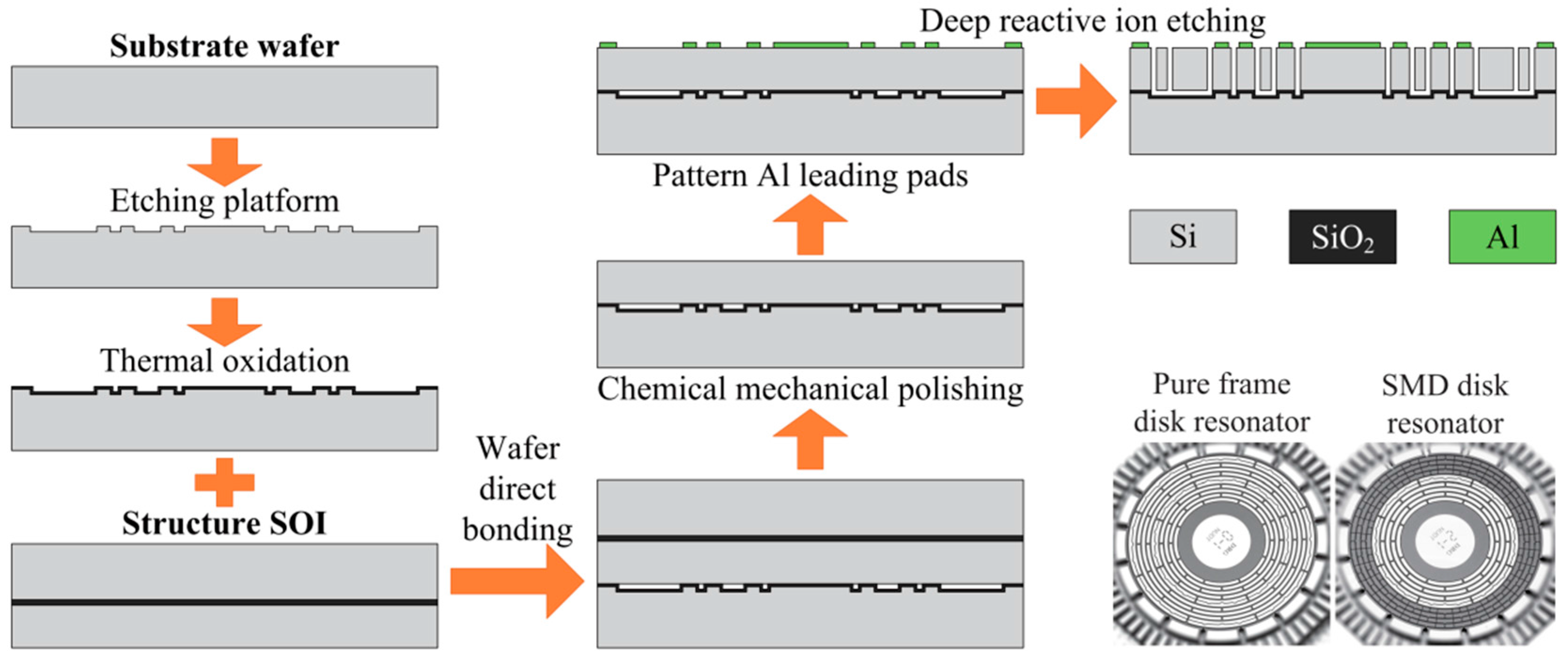
2. Device Description
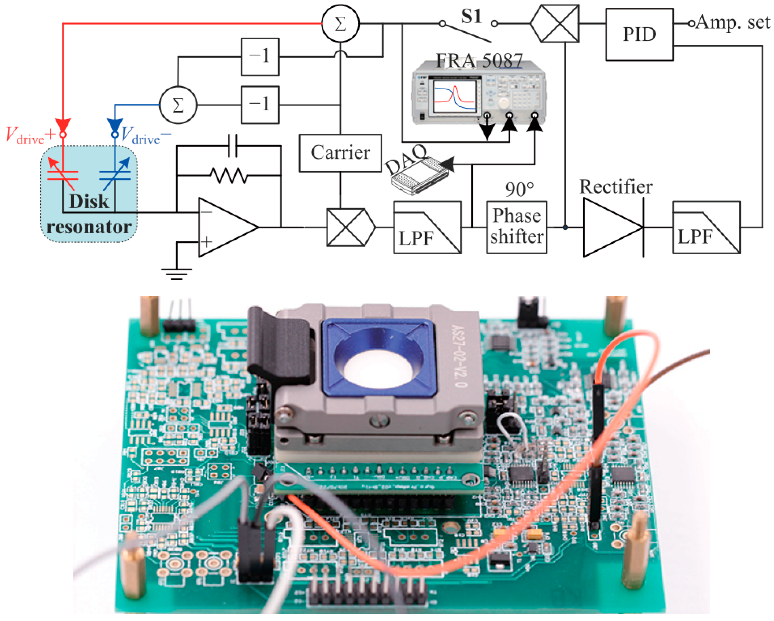
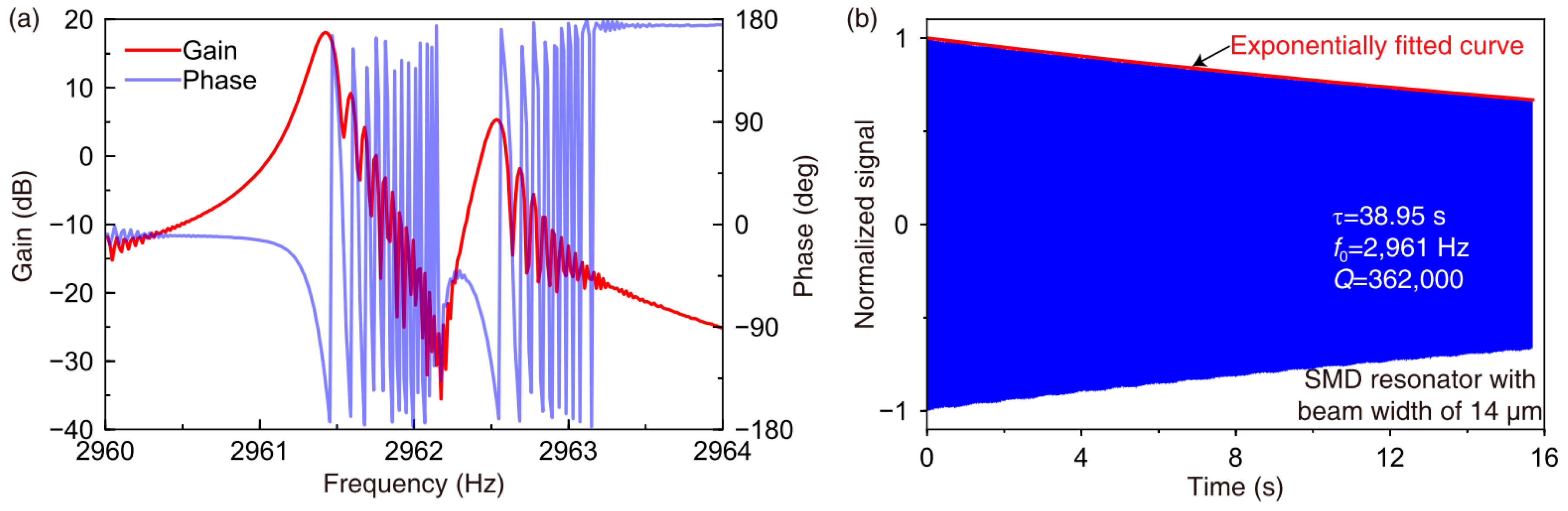
TED is one of the most important damping factors of micromechanical resonators. Strain field in the deformed mechanical resonator will lead to a temperature gradient, which will then result in an irreversible heat flow. The energy dissipation caused by this conversion from mechanical energy to heat is defined as the TED. Zener’s standard model [25,26] is the most widely used theoretical model for TED, which is given by [18]
Q TED = C V E α 2 T 0 1 + ( ω 0 / ω Relax ) 2 ω 0 / ω Relax
ω Relax = χ π 2 b 2
where CV is the heat capacity of the solid. E is the Young’s modulus. α is the coefficient of thermal expansion. T0 is the nominal average temperature. ω0 and ωRelax are the resonant frequency and the thermal relaxation rate, respectively. χ is thermal diffusivity of the solid and b is the width of the strained beam. QTED is a function of resonant frequency and beam width, as shown Figure 1. When ω0 is close to ωRelax, the damping reaches the maximum. The condition of ω0 << ωRelax is defined as isothermal-mode, which is the left side of the “valley” in Figure 1. Conversely, condition of ω0 >> ωRelax is defined as adiabatic-mode, which is the right side of the “valley” in Figure 1.
In this study, disk resonators based on the stiffness-mass decoupling (SMD) design method are developed. The disk resonator is made up of nine concentric rings with an outer diameter of 8000 μm. The outer four layers of rings or the rest of the inner rings are interconnected with 16-fold or eight-fold spokes, respectively. Those rings and spokes have an identical width. The outer rings and spokes are added with lumped silicon mass pieces. The silicon mass pieces with dimensions of 160 μm × 150 μm × l (l = 3 mm–4 mm) are connected to the frame structure using thin beams. The whole structure is suspended on a central anchor with a diameter of 3.760 mm. The layout of the stiffness-mass decoupled disk resonator is shown in Figure 2a. The effective stiffness keff is mainly provided by the frame and the effective mass meff is mainly provided by the lumped masses. Thus, the stiffness and the mass are decoupled. It should be noted that the amount of the lumped mass should be carefully considered, because too low a resonant frequency might be detrimental for a MEMS gyroscope.
The proposed SMD disk resonator works in the isothermal mode. Adding additional lumped masses can greatly reduce the resonant frequency, thus seperate the resonant frequency from the thermal relaxation rate. Compared to the pure-frame structure, the SMD resonator can provide much higher QTED [28]. Besides, the beam width has been altered to further manipulate the QTED. SMD disk resonators with beam widths b ranging from 11 μm to 20 μm were engineered. For comparison, one pure-frame disk resonator is also designed, as shown in Figure 2b. The structural parameters of this resonator is similar to the SMD resonator. Its beam width is designed to be 20 μm.
The designed disk resonators were fabricated using a conventional micromachine process, as depicted in Figure 3. A 500 μm thick (100) single-crystal silicon wafer is used as the substrate wafer. The substrate wafer was etched to create some 5 μm high platforms for bonding. The etched substrate wafer was then thermally oxidized. A silicon-on-insulator (SOI) wafer is used to provide a 150 μm thick (111) structure layer. The structure SOI was bonded with the thermal oxidized substrate wafer using an aligned wafer direct bonding process. The auxiliary handle layer of the SOI was removed by a chemical–mechanical polishing process. Then, the structure layer is patterned with Al leading pads. Lastly, the resonator is fabricated using a deep reactive ion etching process. A fabricated SMD disk resonator and a pure frame disk resonator are also shown in Figure 3.

3. Characterization

The fabricated disk resonator is diced, attached to a ceramic leadless chip carrier, and then wire-bonded. A ring-down experiment was implemented to characterize the Q and decaying time constant τ. The spectrum method is used to find the n = 2 wine-glass modes. The schematic diagram of the experimental circuit is shown in Figure 4. The devices were tested in a vacuum chamber to minimize air damping. The spectrum test is used to obtain the resonant frequency. First, switch S1 was turned off. A sweeping frequency AC signal generated by a frequency response analyzer (NF FRA 5087) was applied on the Spectrum Input port in the circuit. The signal was modulated by a high-frequency carrier signal in order to reduce the low-frequency noise of the front end. The output signal was demodulated and then put in the FRA 5087 from the output port of the circuit. A typical frequency response of the SMD disk resonator is shown in Figure 5a. The frequency was swept upward. Due to the long decaying time constant and the small sweeping time interval, there were some echo signals on the right side of the peaks. Then the ring-down method was implemented to obtain the decaying time constant. First, switch S1 was turned on, and the disk resonator was originally actuated at resonance using self-oscillation. The amplitude of the driving mode was controlled using a proportion-integration-differentiation (PID) controller. Then, the actuation was stopped by turning off S1. The decaying signal in the output port of the circuit was recorded by a data acquisition (DAQ) system. The recorded decaying signal was then filtered, enveloped, and normalized. τ was calculated by fitting the normalized envelope with the function A × e(−t/τ). Q can be calculated based on Q = τω0/2. A typical ring-down result of the SMD disk resonator is shown in Figure 5b.

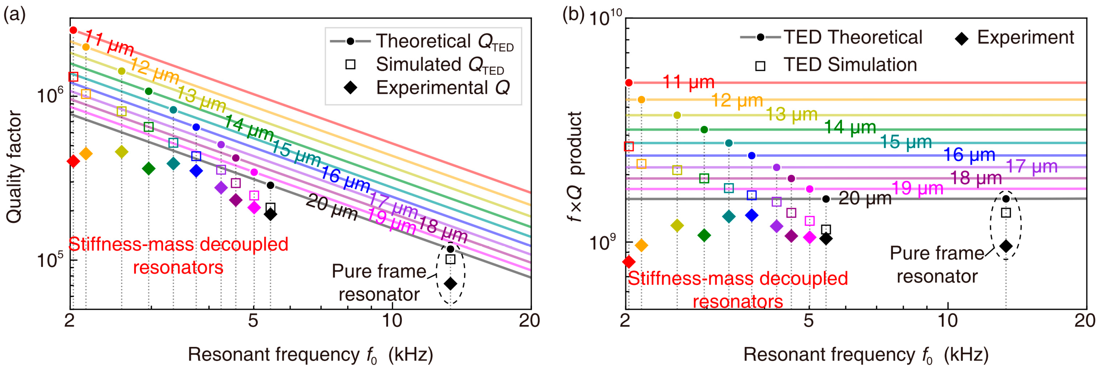
4. Results and Discussion

The QTED of each kind of disk resonator was simulated using COMSOL. The TED simulation concerns the thermoelastic dynamics and thermal diffusion phenomenon. The experimental Qs and simulated QTEDs are illustrated in Figure 6a. The theoretical QTEDs based on Zener’s model are also included. Furthermore, the corresponding f × Q products are illustrated in Figure 6b as well. The effectiveness of the QTED enhancement of the stiffness-mass decoupling method is demonstrated by comparing the 20-μm pure-frame resonator with the 20-μm SMD resonator. When decreasing the beam width of the SMD resonator, QTED is increased, whereas Q stops increasing when it reaches the value around 450,000. This interesting phenomenon indicates that TED is surpassed by another damping mechanism when Q stops increasing. The reduction of the f × Q product when the beam width is smaller than 14 μm can also support this hypothesis.
The quality factor induced by the secondary damping mechanism Qother is estimated to ranging from 577,000 to 1,890,000. A reasonable hypothesis is that this secondary damping is the clamping loss. The unbalanced out-of-plane displacement in the n = 2 wine-glass mode of the disk resonator that is made of (111) silicon is demonstrated here, which has not been cognized before. This unbalanced out-of-plane displacement may produce considerable clamping loss. The (111) silicon was believed to be a good material for symmetrical MEMS devices, because the Young’s modulus, Poisson’s ratio, and shear modulus are isotropic on (111) silicon [32]. However, there is a coupling between the in-plane and the out-of-plane deformation. The relationship between the stress tensor and the strain tensor of (111) silicon in Cartesian coordinate system is given by [33].
[ σ x x σ y y σ z z τ y z τ z x τ x y ] = [ c ¯ 11 c ¯ 12 c ¯ 13 0 c ¯ 15 0 c ¯ 12 c ¯ 11 c ¯ 13 0 c ¯ 15 0 c ¯ 13 c ¯ 13 c ¯ 33 0 0 0 0 0 0 c ¯ 44 0 c ¯ 15 c ¯ 15 c ¯ 15 0 0 c ¯ 44 0 0 0 0 c ¯ 15 0 c ¯ 66 ] [ ε x x ε y y ε z z γ y z γ z x γ x y ]
The subscript of the stiffness matrix are defined as: 1 is xx, 2 is yy, 3 is zz, 4 is yz, 5 is zx, and 6 is xy.
Compared with the stiffness matrix of the (100) silicon, the stiffness matrix of the (111) silicon have coupling term c ¯ 15 . The normal in-plane strain εxx and εyy will contribute to the out-of-plane shearing stress τzx. Thus, the in-plane deformation of the (111) structure will inevitablely cause an out-of-plane deformation. This phenomenon can be verified by simulation. The modal simulation of the disk resonator using (111) silicon and a fully isotropic material were implemented, respectively. The results are depicted in Figure 7. The top view and side view of n = 2 wine-glass mode are demonstrated. There is an unbalanced out-of-plane deformation in the (111) disk resonator. However, no out-of-plane deformation was observed in the fully isotropic disk resonator. The ratio of the out-of-plane to the in-plane amplitutes are from 1:10 to 1:30, which depends on the structure height and beam width. This unbalanced out-of-plane deformation of the (111) disk resonator will cause considerable impact on the clamping loss.
Based on this, Q of the resonators made of (111) silicon will have an upper boundary. For disk resonators, it might be more favorable to use the (100) silicon. In this case, the n = 3 wine-glass mode is recommended instead of the n = 2 wine-glass mode, considering the mode-matching condition.

5. Conclusions

In this paper, the Q upper bond of the (111) disk resonator was demonstrated by engineering very low TED. It was experimental demonstrated that Q stops increasing when it reaches the value around 450,000. In this case, the clamping loss surpasses TED, become the primary damper. The unbalanced out-of-plane displacement caused by the coupling between the in-plane strain and out-of-plane stress was demonstrated. This indicates that the in-plane deformation of the (111) disk resonator could cause as much as 1/30 to 1/10 of out-of-plane deformation, which could cause considerable clamping loss.

Acknowledgments

The authors wish to thank Yi Xu, Peng Wang, Tongqiao Miao of National University of Defense Technology for their assistance in device characterization. The authors also wish to thank Qunying Guo and Dongfang Song of East China Institute of Photo-Electronic IC for their help in device fabrication. This work was supported by the National Natural Science Foundation of China under Grant 51575521.

Author Contributions

Xin Zhou and Dingbang Xiao designed the TED mitigated disk resonators and conceived the experiments; Qingsong Li and Qian Hu explained the out-of-plane deformation of the (111) disk resonator; Zhanqiang Hou and Kaixuan He fabricated the resonators; Zhihua Chen developed the circuits; Chun Zhao provided viewpoints about the anchor loss; Yulie Wu provided analysis and experimental tools; Xuezhong Wu and Ashwin Seshia oversaw and revised this work; Xin Zhou wrote the paper; All authors discussed the results and commented on the manuscript.

Conflicts of Interest

The authors declare no conflict of interest.

Abbreviations

The following abbreviations are used in this manuscript:
MEMSMicroelectromechanical systems
ACAlternating Current

References

  1. Charmet, J.; Michaels, T.C.T.; Daly, R.; Prasad, A.; Thiruvenkathanathan, P.; Langley, R.S.; Knowles, T.P.J.; Seshia, A.A. Quantifying measurement fluctuations from stochastic surface processes on sensors with heterogeneous sensitivity. Phys. Rev. Appl. 2016, 5, 602–608. [Google Scholar] [CrossRef]
  2. Park, K.; Millet, L.J.; Kim, N.; Li, H.; Jin, X.; Popescu, G.; Aluru, N.R.; Hsia, K.J.; Bashir, R. Measurement of adherent cell mass and growth. Proc. Natl. Acad. Sci. USA 2010, 107, 20691–20696. [Google Scholar] [CrossRef] [PubMed]
  3. Nguyen, C.T.C. Frequency-selective MEMS for miniaturized low-power communication devices. IEEE Trans. Microw. Theory Tech. 1999, 47, 1486–1503. [Google Scholar] [CrossRef]
  4. Clark, J.; Hsu, W.; Abdelmoneum, M.; Nguyen, C. High-Q UHF micromechanical radial-contour mode disk resonators. J. Microelectromech. Syst. 2005, 14, 1298–1310. [Google Scholar] [CrossRef]
  5. Nguyen, C.T.C. MEMS technology for timing and frequency control. IEEE Trans. Ultrason. Ferroelectr. Freq. Control 2007, 54, 251–270. [Google Scholar] [CrossRef] [PubMed]
  6. Nitzan, S.H.; Zega, V.; Li, M.; Ahn, C.H.; Corigliano, A.; Kenny, T.W.; Horsley, D.A. Self-induced parametric amplification arising from nonlinear elastic coupling in a micromechanical resonating disk gyroscope. Sci. Rep. 2015, 5, 9036. [Google Scholar] [CrossRef] [PubMed] [Green Version]
  7. Ahn, C.H.; Nitzan, S.; Ng, E.J.; Hong, V.A.; Yang, Y.; Kimbrell, T.; Horsley, D.A.; Kenny, T.W. Encapsulated high frequency (235 kHz), high-Q (100 k) disk resonator gyroscope with electrostatic parametric pump. Appl. Phys. Lett. 2014, 105, 243504. [Google Scholar] [CrossRef]
  8. Middlemiss, R.P.; Samarelli, A.; Paul, D.J.; Hough, J.; Rowan, S.; Hammond, G.D. Measurement of the Earth tides with a MEMS gravimeter. Nature 2016, 531, 614. [Google Scholar] [CrossRef] [PubMed]
  9. Gallacher, B.J.; Hedley, J.; Burdess, J.S.; Harris, A.J.; Rickard, A.; King, D.O. Electrostatic correction of structural imperfections present in a microring gyroscope. J. Microelectromechan. Syst. 2005, 14, 221–234. [Google Scholar] [CrossRef]
  10. Etaki, S.; Konschelle, F.; Blanter, Y.M.; Yamaguchi, H.; van der Zant, H.S.J. Self-sustained oscillations of a torsional SQUID resonator induced by Lorentz-force back-action. Nat. Commun. 2013, 4, 1803. [Google Scholar] [CrossRef] [PubMed]
  11. Schwab, K.; Roukes, M. Putting mechanics into quantum mechanics. Phys. Today 2005, 58, 36–42. [Google Scholar] [CrossRef]
  12. Bao, M.; Yang, H.; Yin, H.; Sun, Y. Energy transfer model for squeeze-film air damping in low vacuum. J. Micromech. Microeng. 2002, 12, 341–346. [Google Scholar] [CrossRef]
  13. Vignola, J.; Judge, J.; Jarzynski, J.; Zalalutdinov, M.; Houston, B.; Baldwin, J. Effect of viscous loss on mechanical resonators designed for mass detection. Appl. Phys. Lett. 2006, 88, 041921. [Google Scholar] [CrossRef]
  14. Mohanty, P.; Harrington, D.; Ekinci, K.; Yang, Y.; Murphy, M.; Roukes, M. Intrinsic dissipation in high-frequency micromechanical resonators. Phys. Rev. B 2002, 66, 085416. [Google Scholar] [CrossRef]
  15. Unterreithmeier, Q.P.; Faust, T.; Kotthaus, J.P. Damping of Nanomechanical Resonators. Phys. Rev. Lett. 2010, 105, 027205. [Google Scholar] [CrossRef] [PubMed]
  16. Cole, G.D.; Wilson-Rae, I.; Werbach, K.; Vanner, M.R.; Aspelmeyer, M. Phonon-tunnelling dissipation in mechanical resonators. Nat. Commun. 2011, 2, 231. [Google Scholar] [CrossRef] [PubMed]
  17. Darvishian, A.; Shiari, B.; Cho, J.Y.; Nagourney, T.; Najafi, K. Anchor Loss in Hemispherical Shell Resonators. J. Microelectromech. Syst. 2017, 26, 51–66. [Google Scholar] [CrossRef]
  18. Lifshitz, R.; Roukes, M.L. Thermoelastic damping in micro- and nanomechanical systems. Phys. Rev. B 2000, 61, 5600–5609. [Google Scholar] [CrossRef]
  19. Chandorkar, S.A.; Candler, R.N.; Duwel, A.; Melamud, R.; Agarwal, M.; Goodson, K.E.; Kenny, T.W. Multimode thermoelastic dissipation. J. Appl. Phys. 2009, 105, 043505. [Google Scholar] [CrossRef]
  20. Wong, S.J.; Fox, C.H.J.; McWilliam, S.; Fell, C.P.; Eley, R. A preliminary investigation of thermo-elastic damping in silicon rings. J. Micromech. Microeng. 2004, 14, S108–S113. [Google Scholar] [CrossRef]
  21. Challoner, A.D.; Ge, H.H.; Liu, J.Y. Boeing disc resonator gyroscope. In Proceedings of the 2014 IEEE/ION Position, Location and Navigation Symposium, Monterey, CA, USA, 5–8 May 2014; pp. 504–514. [Google Scholar]
  22. Duwel, A.; Candler, R.N.; Kenny, T.W.; Varghese, M. Engineering MEMS resonators with low thermoelastic damping. J. Microelectromech. Syst. 2006, 15, 1437–1445. [Google Scholar] [CrossRef]
  23. Gerrard, D.D.; Ahn, C.H.; Flader, I.B.; Chen, Y.; Ng, E.J.; Yang, Y.; Kenny, T.W. Q-factor optimization in disk resonator gyroscopes via geometric parameterization. In Proceedings of the Micro Electro Mechanical Systems MEMS 2016, Shanghai, China, 24–28 January 2016; pp. 994–997. [Google Scholar]
  24. Gerrard, D.D.; Rodriguez, J.; Ortiz, L.C.; Chandorkar, S.A.; Flader, I.B.; Chen, Y.; Shin, D.D.; Kenny, T.W. Manipulation of heat flux paths in thermo-elastically damped resonators for Q optimization. In Proceedings of the Micro Electro Mechanical Systems MEMS 2017, Las Vegas, NV, USA, 22–26 January 2017; pp. 1130–1133. [Google Scholar]
  25. Xiao, D.; Zhou, X.; Li, Q.; Hou, Z.; Xi, X.; Wu, Y.; Wu, X. Design of a disk resonator gyroscope with high mechanical sensitivity by optimizing the ring thickness distribution. J. Microelectromech. Syst. 2016, 25, 606–616. [Google Scholar] [CrossRef]
  26. Zhou, X.; Xiao, D.; Hou, Z.; Li, Q.; Wu, Y.; Wu, X. Influences of the structure parameters on sensitivity and Brownian noise of the disk resonator gyroscope. J. Microelectromech. Syst. 2017, 26, 519–527. [Google Scholar] [CrossRef]
  27. Zhou, X.; Wu, Y.; Xiao, D.; Hou, Z.; Li, Q.; Yu, D.; Wu, X. An investigation on the ring thickness distribution of disk resonator gyroscope with high mechanical sensitivity. Int. J. Mech. Sci. 2016, 117, 174–181. [Google Scholar] [CrossRef]
  28. Zhou, X.; Xiao, D.; Wu, X.; Wu, Y.; Hou, Z.; He, K.; Li, Q. Stiffness-mass decoupled silicon disk resonator for high resolution gyroscopic application with long decay time constant (8.695 s). Appl. Phys. Lett. 2016, 109, 263501. [Google Scholar] [CrossRef]
  29. Zhou, X.; Xiao, D.; Wu, X.; Li, Q.; Hou, Z.; He, K.; Wu, Y. Mitigating Thermoelastic Dissipation of Flexural Micromechanical Resonators by Decoupling Resonant Frequency from Thermal Relaxation Rate. Phys. Rev. Appl. 2017, 8, 064033. [Google Scholar] [CrossRef]
  30. Zhou, X.; Xiao, D.; Hou, Z.; Li, Q.; Wu, Y.; Yu, D.; Li, W.; Wu, X. Thermoelastic quality-factor enhanced disk resonator gyroscope. In Proceedings of the Micro Electro Mechanical Systems MEMS 2017, Las Vegas, NV, USA, 22–26 January 2017; pp. 1009–1012. [Google Scholar]
  31. Rodriguez, J.; Gerrard, D.D.; Chandorkar, S.; Chen, Y.; Glaze, G.M.; Flader, I.B.; Ahn, C.H.; Ng, E.J.; Kenny, T.W. Wide-range temperature dependence studies for devices limited by thermoelastic dissipation and anchor damping. In Proceedings of the 2017 19th International Conference on Solid-State Sensors, Actuators and Microsystems, Kaohsiung, Taiwan, 18–22 June 2017; pp. 1100–1103. [Google Scholar]
  32. Kim, J.; Cho, D.-I.; Muller, R.S. Why is (111) silicon a better mechanical material for MEMS? In Transducers ’01 Eurosensors XV; Obermeier, E., Ed.; Springer: Berlin, Germany, June 2001; pp. 662–665. [Google Scholar]
  33. Chang, C.-O.; Chang, G.-E.; Chou, C.-S.; Chang Chien, W.-T.; Chen, P.-C. In-plane free vibration of a single-crystal silicon ring. Int. J. Solids Struct. 2008, 45, 6114–6132. [Google Scholar] [CrossRef]
Figure 1. QTED of the single-crystal-silicon resonators based on Zener’s model as a function of resonant frequency and beam width. The left side of the “valley” is in isothermal mode, and the right side of the “valley” is in adiabatic mode.
Micromachines 09 00025 g001
Figure 2. (a) Schematic of the stiffness-mass decoupled disk resonator. Beam width b is altered from 11 μm to 20 μm. (b) Schematic of a pure-frame disk resonator.
Micromachines 09 00025 g002
Figure 3. Fabrication process of the disk resonators. The photographs of a fabricated SMD disk resonator and a pure frame disk resonator are also shown.
Micromachines 09 00025 g003
Figure 4. Schematic diagram of the circuit for spectrum and ring-down experiments (up) and the testing circuit board (down).
Micromachines 09 00025 g004
Figure 5. (a) Typical frequency response and (b) ring-down signal of the n = 2 wineglass mode of a SMD disk resonator with beam width of 14 μm.
Micromachines 09 00025 g005
Figure 6. (a) Experimental Qs, simulated QTEDs, and theoretical QTEDs of the SMD disk resonators with beam width ranging from 11 μm to 20 μm and those of the pure frame disk resonator with beam width of 20 μm. (b) f × Q products obtained by TED theory, TED simulation, and Experiment for the SMD disk resonators with beam width ranging from 11 μm to 20 μm and those of the pure frame disk resonator with beam width of 20 μm.
Micromachines 09 00025 g006
Figure 7. (a) Top view of the n = 2 wine-glass mode of the SMD disk resonator; (b) Side view of the SMD disk resonator that is made of (111) silicon. The scale of the out-of-plane deformation is amplified by 50 times; (c) Side view of the SMD disk resonator that is made of a fully isotropic material.
Micromachines 09 00025 g007

