1. Introduction
Recent years have seen the emergence of microfluidic droplet technology in a variety of chemical and biochemical applications [
1,
2], ranging from single-cell analysis [
3,
4,
5,
6] to enzyme kinetics measurements [
7,
8] and even nanoparticle synthesis [
9,
10,
11]. In particular, microfluidic droplets have proven pivotal in digital analysis of individual biological samples at the single-molecule level [
12,
13,
14,
15]. While this technology offers the capacity to divide a homogeneous reaction (
i.e., one sample against one set of reagents) into a large number of reactions in droplets, it nevertheless faces challenges in generating a large combination of sample-reagent mixtures in a multiplexed manner. Additionally, although approaches such as integrated picoinjectors [
16,
17], segregated microfluidic plugs in tubing [
18,
19,
20,
21], and multiple devices [
22] have been demonstrated to improve the multiplexing capacity of microfluidic droplet platforms, there remains a critical need for alternative approaches that facilitate multiplexed experiments in droplets.
As a promising alternative, droplet microfluidic devices that utilize programmable microfluidic valves to mix combinations of samples and reagents on-demand [
23,
24,
25,
26,
27,
28,
29] present a viable approach to performing multiplexed experiments in microfluidic droplets. For example, such devices have been employed to demonstrate multiplexed experiments, such as the detection of DNA [
26,
28] and characterization of matrix metalloproteases [
25,
29]. Importantly, in some of these devices, the conservation of positional order of each droplet after combinatorial assembly enables spatial indexing as an effective means to track droplets [
27,
29]. Unfortunately, a key limitation to this platform is its throughput. Because the combinatorial droplets are generated sequentially and serially, the rate of analysis is limited by the rate at which droplets can be assembled and detected in the order of assembly (
Figure 1A). A design that can increase the throughput of such microvalve-based combinatorial droplet devices is therefore needed.
Figure 1.
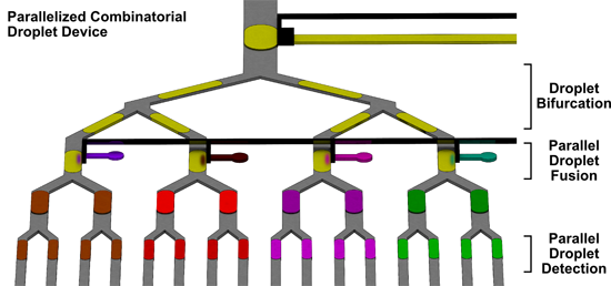
Improving Throughput of Combinatorial Droplet Devices via Parallelization. (A) In the traditional design, sample droplets (S) are fused with designated reagents (R1–R4) one at a time to generate the train of combinatorial droplets (S + R1, etc.), which maintain their spatial index within the single channel before they are sequentially optically detected. (B) The current design leverages parallelized operation via droplet bifurcation, parallel reagent injection, and parallel detection to improve the throughput. Specifically, each sample droplet first travels through bifurcating Y-junctions (two stages, as shown here) and splits into identical daughter droplets (four, as shown here) before each daughter droplet is fused with its designated reagent via direct injection. Importantly, the reagents can be simultaneously injected into the daughter droplets, thereby facilitating improved throughput. Finally, detection of fused droplets can be performed one group at a time, further ensuring high-throughput operation within the device.
Figure 1.
Improving Throughput of Combinatorial Droplet Devices via Parallelization. (A) In the traditional design, sample droplets (S) are fused with designated reagents (R1–R4) one at a time to generate the train of combinatorial droplets (S + R1, etc.), which maintain their spatial index within the single channel before they are sequentially optically detected. (B) The current design leverages parallelized operation via droplet bifurcation, parallel reagent injection, and parallel detection to improve the throughput. Specifically, each sample droplet first travels through bifurcating Y-junctions (two stages, as shown here) and splits into identical daughter droplets (four, as shown here) before each daughter droplet is fused with its designated reagent via direct injection. Importantly, the reagents can be simultaneously injected into the daughter droplets, thereby facilitating improved throughput. Finally, detection of fused droplets can be performed one group at a time, further ensuring high-throughput operation within the device.
![Micromachines 06 01434 g001]()
To address this limitation, we have developed a parallelized combinatorial droplet device design. This design is achieved via droplet splitting [
30,
31,
32,
33,
34,
35,
36], parallelized droplet fusion, and parallelized droplet detection (
Figure 1B). Specifically, each sample droplet first travels through bifurcating Y-junctions (two stages, as shown here) and split into identical daughter droplets (four, as shown here) before each daughter droplet is fused with its designated reagent. Importantly, the reagents can be simultaneously injected into the daughter droplets, thereby facilitating improved throughput. Finally, the entire group of fused sample-reagent droplets originating from the single sample droplet can be detected in parallel, further enhancing the throughput. To demonstrate this concept, we designed and fabricated a parallelized combinatorial droplet device and showed that the new design can improve the device throughput by 16-fold when compared to a traditional, single-channel design—with ready potential for further enhancement.
3. Results
3.1. Device Design and Workflow
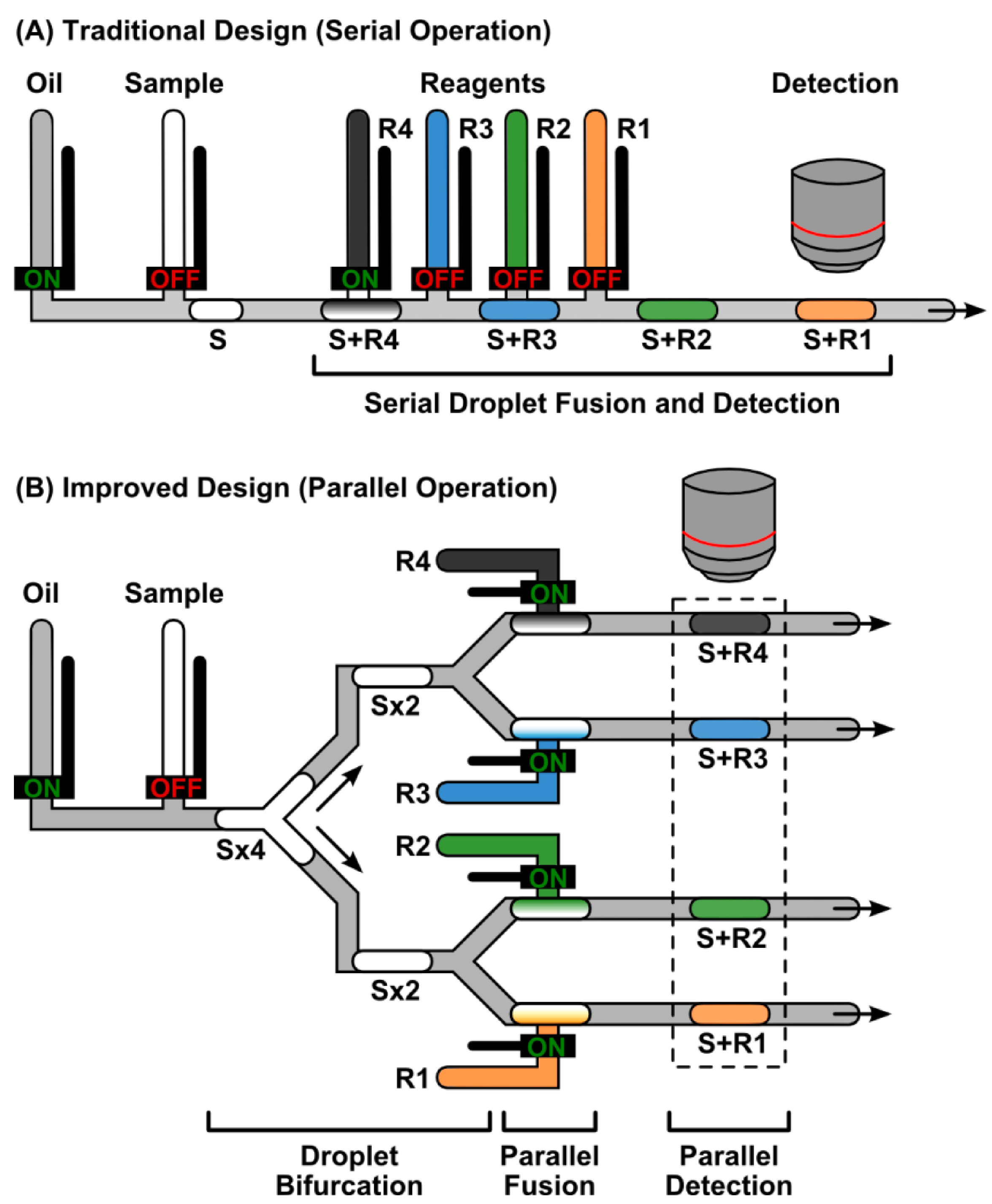
We have designed a microfluidic device to support parallelized combinatorial droplet workflow (
Figure 2). The microfluidic device employs a two-layer architecture where the flow of oil, sample droplets, and reagent droplets in the fluidic layer (
Figure 2, blue) is regulated by designated microvalves in the valve layer (
Figure 2, red). The fluidic channel—where the droplet generation, bifurcation, fusion, and detection occur—undergoes several splits, connects with reagent inlet channels, and eventually divides into 16 channels with the same length and, hence, the same fluidic resistance. The most upstream inlet is reserved for the carrier oil, which drives all flow in the device. Downstream to the oil inlet are two sample inlets with corresponding rinsing channels (
Figure 2, insert micrograph 1) connected to the central carrier oil channel. Two pressure relief channels near the sample inlets ensure the uniformity of sample droplets by decoupling droplet generation from fluidic resistance of the incubation channel. The central carrier oil channel splits into two identical halves at a bifurcating Y-junction. For all four stages of bifurcation Y-junctions, the angle is 45° and the two outgoing channels shrink in width by a factor of
(e.g., for the first stage of bifurcating Y-junction, the single incoming channel has a width of 200 μm, and each of the two outgoing channels has a width of 140 μm) [
32,
33]. After the first two stages of bifurcation, each of the four resulting fluidic channels is connected with a reagent channel that is individually controlled by a microvalve for programmable reagent injection (
Figure 2, R1–R4; insert micrograph 2). Importantly, in the general reagent injection region, the cross-section of fluid channels are designed such that the sample daughter droplets can be elongated to be several-fold longer than the width of the reagent inlet channel. As such, reagents can be directly injected into the sample droplets and fused, removing the need for droplet synchronization. Each fluidic channel subsequently goes through two additional bifurcating Y-junctions (
Figure 2, insert micrograph 3), resulting in 16 serpentine incubation channels to accommodate four replicates of the four different reaction conditions. All incubation channels are designed to have the same length to ensure equal fluidic resistance, which is critical for droplet uniformity. Finally, at the detection zone, the pitch between adjacent channels decreases to 50 μm such that all 16 50-μm-wide incubation channels can be viewed within a microscope viewing area (using a 4× objective lens), thus facilitating parallel detection via microscopy (
Figure 2, insert micrograph 4).
In our device, droplet bifurcation and subsequent parallelized reagent injection, droplet fusion, and droplet detection are performed in a streamlined workflow to maximize the throughput. Here, all microvalves are kept under positive pressure so that they are normally closed; they are opened on-demand to achieve injection. The carrier oil, samples, and reagents are pre-loaded into their designated inlets and are kept under constant pressure, so that when microvalves are opened, these fluids can be injected to form and subsequently maneuver droplets. Sample droplets are first generated by briefly opening the sample microvalve, and upon closing the sample microvalve and opening the oil microvalve, are pushed through the first two stages of bifurcating Y-junctions, producing a total of four identical daughter droplets. As the sample droplets flow through the reagent injection region, the four reagent microvalves are opened momentarily to inject reagents directly into elongated sample daughter droplets and achieve droplet fusion. Parallelized injection of reagents therefore improves the throughput by four-fold. Fused sample-reagent droplets go through two additional bifurcating Y-junctions such that each injection of sample and reagents results in a total of 16 droplets (four replicates of four different conditions). Performing triplicates or higher number of replicates is important for biochemical experiments. In benchtop experiments, replicates are typically split from a stock via pipetting. In our device, we leverage bifurcating Y-junctions to split each sample-reagent droplet into four replicates. This built-in mechanism for replication obviates serially generating replicates, thus providing an additional four-fold improvement in throughput. Each daughter droplet then flows through its serpentine incubation channel and arrives simultaneously with all other daughter droplets in the same group at the detection zone, thus facilitating parallel detection via microscopy (see
Supplementary Video S1). Notably, the volume of fused droplets is controlled to span the cross-section of all fluid channels, as this is critical to maintain the spatial indices of all droplets.
Figure 2.
Parallelized Combinatorial Droplet Device. The microfluidic device employs a two-layer architecture where the flow of oil, sample droplets, and reagent droplets in the fluid layer (blue) is regulated by designated valves in the valve layer (red). The most upstream inlet is reserved for the carrier oil, which drives droplet formation and flow. Downstream to the oil inlet are two sample inlets with corresponding rinsing channels (insert micrograph 1) connected to the fluid channel. The fluid channel splits into two identical halves at a bifurcating Y-junction and each of the four resulting fluid channels is connected with a reagent channel that is individually controlled by a microvalve for programmable reagent injection (R1–R4; insert micrograph 2). In our device, reagents can be directly injected into the sample droplets and fused, removing the need for droplet synchronization. Each fluid channel subsequently goes through two additional bifurcating Y-junctions (insert micrograph 3), resulting in a total of 16 serpentine incubation channels to accommodate four replicates of the four different reaction conditions. Finally, at the detection zone, the pitch between adjacent channels decreases such that all 16 channels can be viewed within a microscope viewing area, thus facilitating parallel detection via microscopy (insert micrograph 4).
![Micromachines 06 01434 g002]()
3.2. Uniform Droplet Splitting
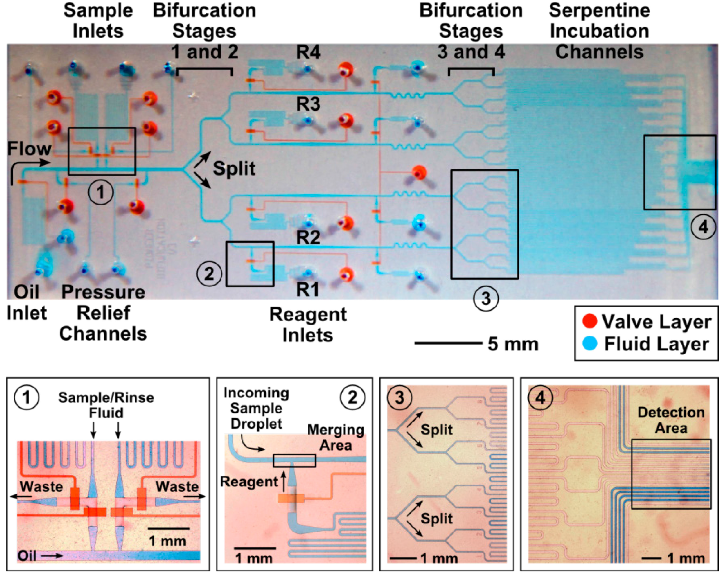
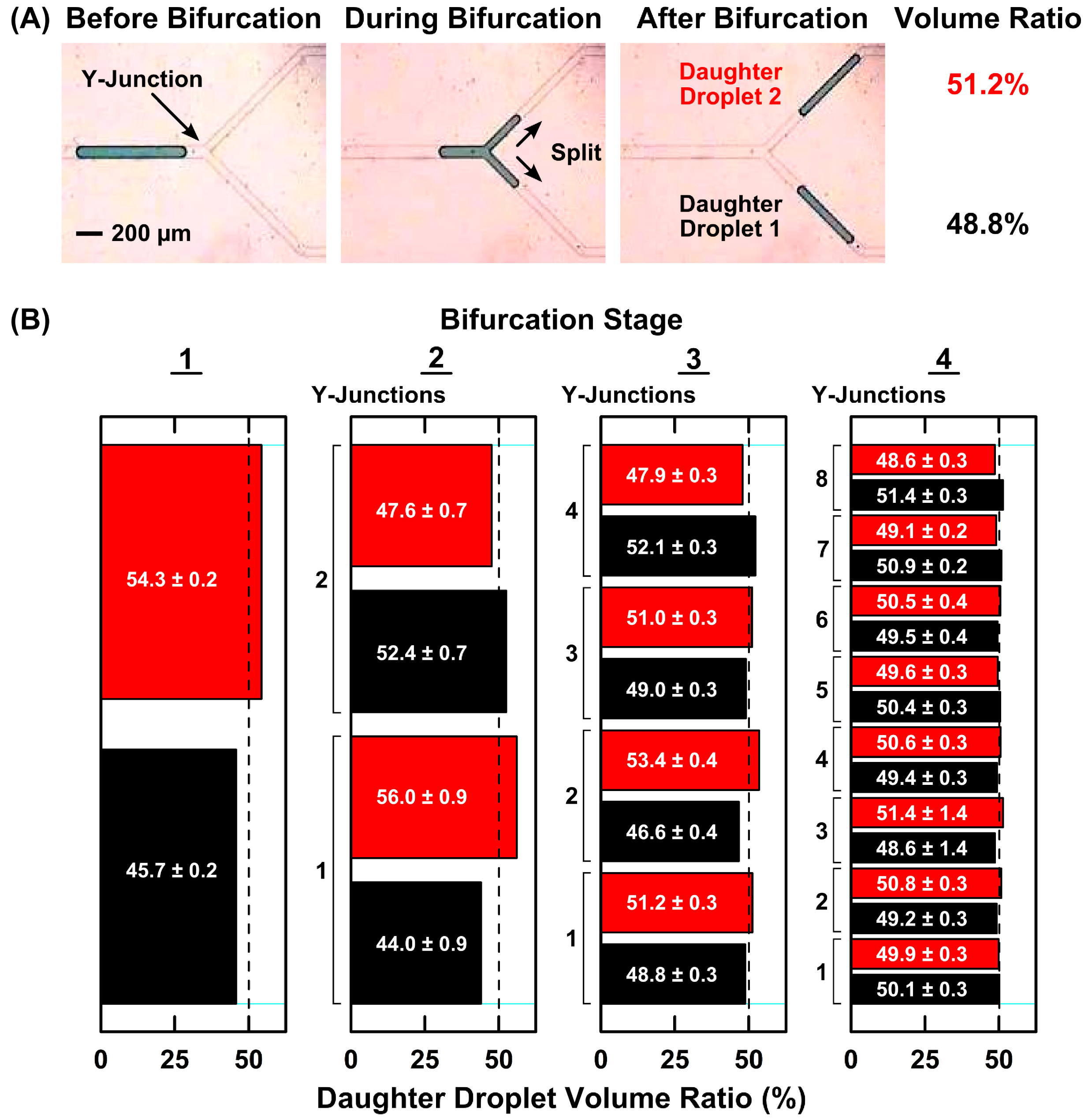
We first demonstrated uniform droplet splitting in our device, which is a critical prerequisite to the parallelized operation of our device. To demonstrate this, we generated a series of sample droplets (volume = ~10 nL; frequency = 0.5 Hz) with black food dye as the sample because this dye produced sharp color contrast and was empirically found to travel through the device with minimal sticking, and thus facilitated downstream operation and analysis. These samples droplets were uniform in size, with a 1.7% coefficient of variation (CV). We then allowed them to travel downstream and continuously bifurcate through four stages of bifurcation Y-junctions. By recording videos of droplet splitting at all Y-junctions and extracting screenshot images from the videos, we clearly observed droplets splitting into two even halves as they flow through a bifurcation Y-junction (
Figure 3A).
To quantitatively analyze the bifurcation performance across the four bifurcation stages, we used image analysis software to determine the volume of the pair of split droplets after splitting at each of the 15 Y-junctions and calculated the ratio of the volume of each droplet over the combined volume. As such, a volume ratio of 50% for both daughter droplets indicates even droplet splitting. In our devices, we had measured ~50% volume ratio of daughter droplets at the four different stages and the 15 Y-junctions (
Figure 3B;
n = 10 for each Y-junction), indicating fairly uniform droplet splitting. Furthermore, uniform droplet bifurcation across the different stages of Y-junctions validates that Y-junctions enable uniform droplet splitting even with different Y-junction channel dimensions and droplet volumes. It should be noted, however, that ~10% difference in volume ratio of daughter droplets could be observed at the first two stages of bifurcating Y-junctions. Such variations would continue through the rest of the device. When we measured the volumes of the split daughter droplets at bifurcation stages 1, 2, 3, and 4, we measured CVs of 9.2%, 12.6%, 9.1%, and 8.2%, respectively. In addition to ensuring more uniform droplet sizes, examining the effect of such size variations on bioassays are subjects for our follow-up studies.
In order to achieve more uniform droplet splitting, it is critical to maintain the same fluidic resistance across all fluidic channels that flow in parallel. Here, we had carefully examined our devices to ensure the fluid channels are free of obstructions due to defects in the master mold. We had also found a potential source for severely increasing the fluidic resistance of a particular fluid channel is an overlaying valve control channel, as that may cause the fluid channel to sag down and increase the fluidic resistance. In our design, we had avoided overlaying valve control channels on top of fluid channels. For the only occurrence, we designed the valve control channel to overlay the four fluid channels equally, and we narrowed the valve control channel to prevent it from sagging into the fluid channels. Finally, we had designed filter structures at all sample and reagent inlets to prevent channel clogging, which can also severely increase the fluidic resistance of a particular fluid channel and disrupt droplet splitting.
Figure 3.
Uniformity of Droplet Bifurcation. (A) In our device, microfluidic droplets split into two equal halves as they flow through a bifurcating Y-junction. To quantitatively analyze the bifurcation performance at the Y-junction, we determine the volume of the pair of daughter droplets after splitting and calculate the ratio of the volume of each daughter droplet over the combined volume of the two droplets; (B) We measured ~50% volume ratio for all daughter droplets across the four bifurcation stages and the 15 Y-junctions (n = 10 for each Y-junction), suggesting that uniform droplet bifurcation is independent of channel dimensions and droplet volumes.
3.3. Parallelized Injection of Reagents with Individualized Calibration
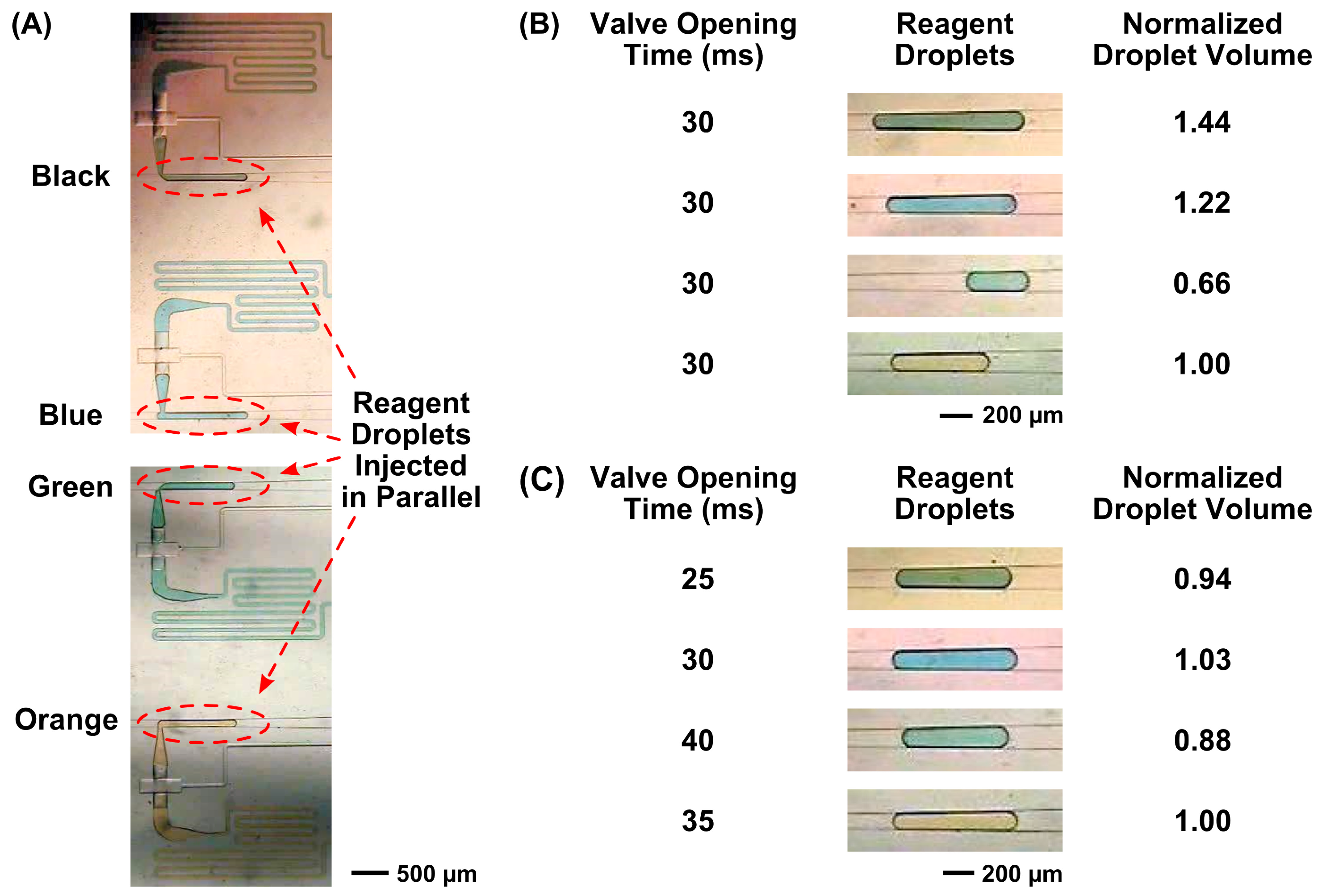
We have designed our device to simultaneously inject multiple, independent reagents in parallel, which provides ready means to improve the throughput. To demonstrate this capability, we pre-loaded each reagent inlet with a different color of food dye (orange, green, blue, and black in this case) and simultaneously actuated the microvalves that control the reagent inlets to form four reagent droplets in parallel. Indeed, a simultaneous actuation of all four reagent microvalves resulted in four independent reagent droplets in their respective channels (
Figure 4A). As such, injection of the four reagents in parallel instead of one-by-one as in our previous combinatorial droplet devices resulted in a four-fold improvement in the throughput.
Importantly, the individually controlled reagent inlets in our device allow us to calibrate each inlet independently and to ensure consistent and accurate volume injection across parallel reagent channels. For example, when we loaded four different colors of food dye (orange, green, blue, and black) as the reagents and programmed the four reagent microvalves to open with an identical opening time (e.g., 30 ms), the four resulting droplets differed by as much as 44% in normalized droplet volume (
Figure 4B). This variation could be caused by the PDMS membranes in our device, as the membranes can vary in thickness from the soft lithography fabrication process. Moreover, variations in reagent viscosity can also lead to variability in droplet sizes as well [
40,
41]. Based on visually observing the initial size of the reagent droplets, we subsequently shortened or lengthened the opening time for each reagent microvalve. With such simple adjustments, we were able to generate reagent droplets with significantly improved uniformity; the variation in normalized droplet volume reduced to <12% (
Figure 4C). The improved size uniformity in reagent droplets thus showed that we could effectively correct reagent droplets with different sizes with our individually addressable reagent inlets. Further improvements in the uniformity could be achieved by performing a few iterations of measuring the volume of reagent droplets via image analysis before fine-tuning the microvalve opening time.
Figure 4.
Parallelized Quadplex Injection of Reagent Droplets with Capacity for Individualized Calibration. (A) Parallelized injection of multiple reagents can be readily achieved in our device, as a simultaneous actuation of all four reagent microvalves results in four independent reagent droplets in their respective channels. (B) Variations in reagent inlet microvalves and differences in the viscosity of food dyes can lead to reagents droplets with different sizes. For example, when we injected four different colors of food dyes with an identical microvalve opening time (e.g., 30 ms), the four resulting reagent droplets can differ by as much as 44% in normalized droplet volume. (C) By adjusting the microvalve opening time of each individually-addressable reagent microvalve, reagent droplets with significantly improved size uniformity can be generated.
3.4. Reliable Droplet Fusion in Parallel
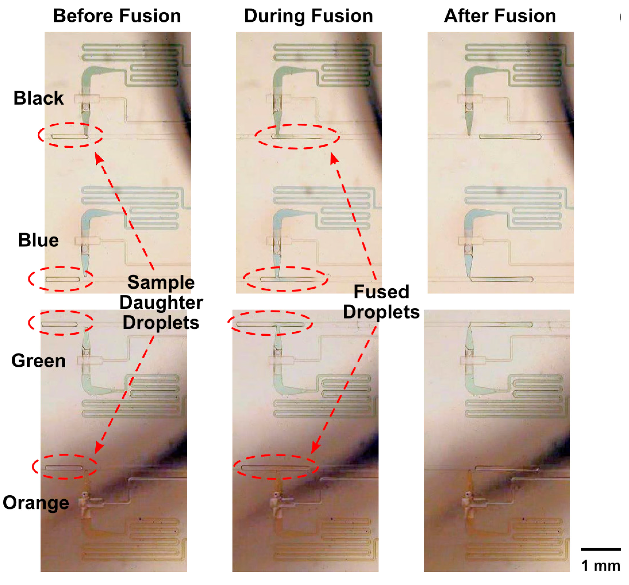
Having demonstrated uniform droplet splitting and uniform reagent injection in parallel, we subsequently combined these two functions and demonstrated robust, parallelized fusion of sample and reagent droplets. We first confirmed reliable droplet fusion visually and qualitatively by using a polymerase chain reaction (PCR) buffer as the sample (due to its clear color and negligible sticking to the device) and four different colors of food dye as the four reagents. Here, we generated a series of sample droplets at ~0.25 Hz and moved them through the first two bifurcation stages. Importantly, our design enforced an elongated shape for each of the four bifurcated daughter sample droplets as they traveled past the four reagent inlets, thus allowing us to directly inject reagents into them for robust droplet fusion (
Figure 5; also see
Supplementary Video S2).
We note several parameters that facilitate reliable, parallelized fusion of sample and reagent droplets. First, we designed the channels downstream to the reagent inlets to gradually widen, which caused droplets to slow down following reagent injection and facilitated fusion of sample and reagent droplets that may not have fused at the time of reagent injection. Second, we employed a combination of FC40 and PFO as the carrier oil, which facilitated direct injection of reagents into sample droplets and their fusion. Finally, we tuned the back pressure applied to the reagent inlets to prevent fission of sample droplets during reagent injection.
Parallelized fusion of sample droplets and reagent droplets was observed to maintain an efficiency of nearly 100% in our device. We quantitatively evaluated the fusion performance in all four channels of our device by performing the same droplet fusion experiment but using only the black food dye as the reagent in all four reagent channels in order to minimize potential experimental variations due to the viscosities of different food dyes. Using video and image analysis to evaluate the droplet fusion in all four channels, we defined droplet fusion efficiency as the ratio between fused droplets and all droplets after the fusion step. The fusion efficiencies were between 98.1% (n = 52), 99.1% (n = 107), 99.1% (n = 107), and 94.5% (n = 55) for the four channels, indicating reliable droplet fusion. These results show that droplets could be reliably fused without having to pause momentarily at the reagent inlets. Such capacity for continuous yet reliable droplet fusion thus presents key feature for enhancing the throughput in our device.
Figure 5.
Parallel Fusion of Sample Droplets with Reagent Droplets. In our device, the four split sample droplets (after two bifurcations) maintain an elongated shape as they travel past the four reagent inlets, allowing direct injection of reagents into them for robust droplet fusion simultaneously in all four channels.
3.5. Parallelized Droplet Incubation and Imaging-Based Detection
In the current device, droplets were incubated as they flowed through their designated incubation channels. Here, after fusion between sample and reagent droplets, each fused droplet first split into four replicates after flowing through two bifurcation stages. Subsequently, each of the 16 sample-reagent droplets (four replicates of four independent sample-reagent combinations) flowed through its own incubation channel. These 16 incubation channels were designed to have identical lengths and cross-section areas to ensure the same fluidic resistance, which allowed the droplets to flow at relatively the same rate before they were imaged in parallel. For proof-of-principle, we designed the incubation channels to be 100 mm long, which supported a brief, ~5 min incubation when the carrier oil was subjected a backpressure of 10 psi. Notably, we could increase the incubation time by reducing the backpressure or lengthening the incubation channels, which would be particularly useful for performing bioassays in future iterations of our device in the near future.
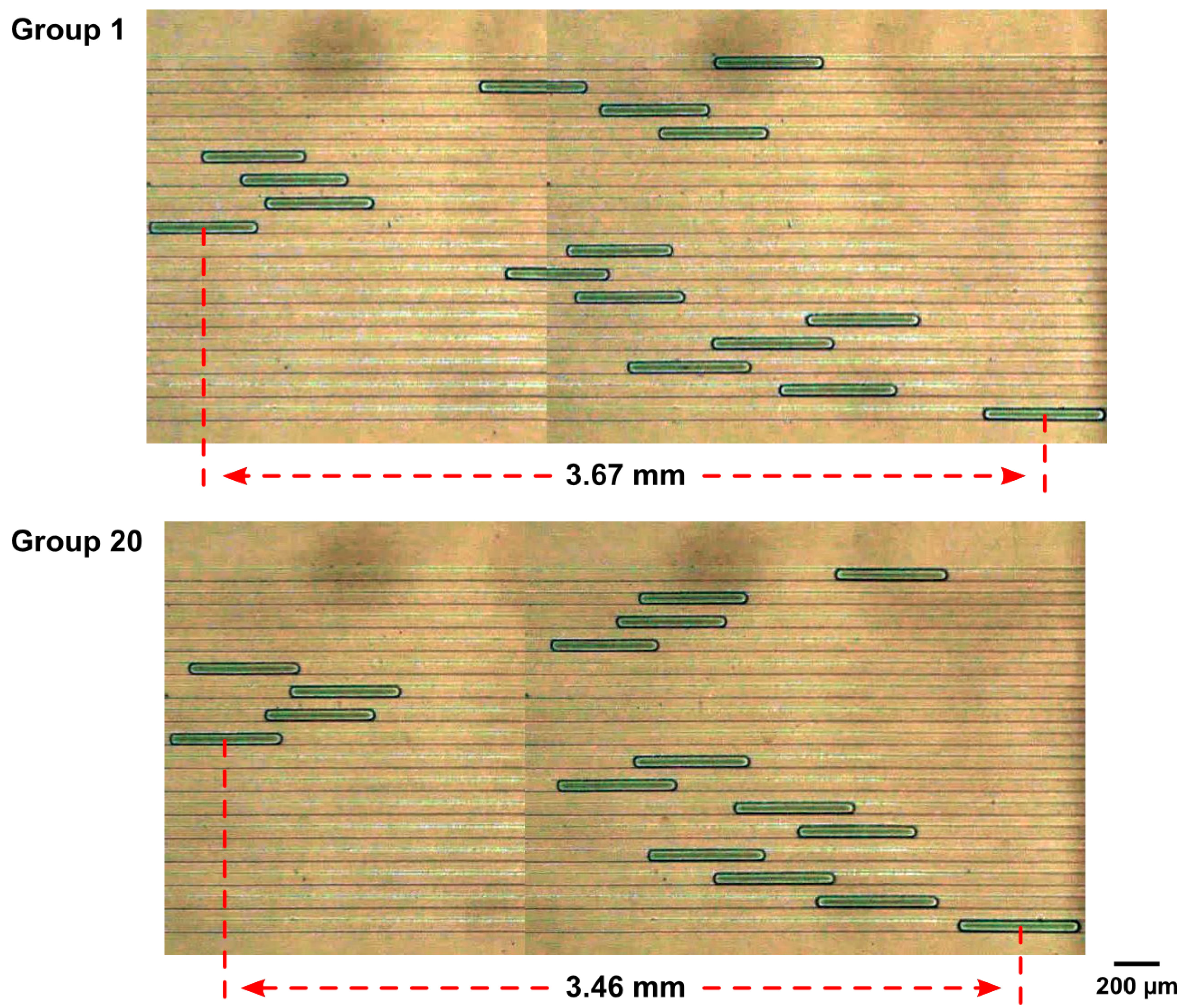
After incubation, we used microscopy to simultaneously image and hence analyze fused droplets in all 16 incubation channels. This imaging approach for parallelized detection is facilitated by designing the detection zone of the device to fit within the field of view of microscopes (under 4× microscope objective lens). To show parallelized droplet detection, we generated multiple groups of 16 droplets (four replicates of the four sample-reagent combination) and imaged them at the detection zone. Here, due to uniform droplet splitting, uniform reagent injection, and robust droplet fusion, the 16 droplets in each group had uniform sizes. For example, the droplet sizes in Group 1 had only an 8.0% CV and remained uniformly sized in Group 20, with a 6.6% CV (
Figure 6). Importantly, the droplets traveled at relatively the same speed through their own incubation channels and thus allowed their spatial indices to be maintained. Indeed, for the droplets in Group 1, we measured that the 16 droplets varied by only as much as 3.67 mm in position after traveling through the 100-mm-long incubation channels, equivalent to a 3.67% variation. For the droplets in Group 20, the maximum difference in position for the 16 droplets was only 3.46 mm. Furthermore, when comparing Group 1 and Group 20, the 16 droplets generally maintained their position relative to one another. For example, the leading droplets in both groups are in incubation channel 1 (counting from bottom) and the trailing droplets in both groups are in incubation channel 9 (counting from bottom). We note that, because the detection area is only 2.5 mm in length, we combined and aligned two screenshots in order to measure the position of all 16 droplets in each group. Nevertheless, these results showed that the droplets in the parallel detection area could indeed be tracked via spatial indexing.
4. Discussion
The parallelized reagent assembly approach described in this work presents an alternative approach to device architecture for droplet microfluidics. Devices employing shear-flow droplet generation has capacity for extremely high throughput, but their limited capacity for in-line combinatorial assembly of reagents has confined their utility to simple, throughput-based applications such as digital PCR. Our parallelized design presents an alternative architecture with greater flexibility for reagent assembly, while demonstrating the potential for parallel processing to bridge the gap in throughput. For example, even operating under a conservative 0.25 Hz generation rate for sample droplets, which equates to a 4 Hz generation rate for fused sample-reagent droplets, a single parallelized combinatorial droplet device is capable of detecting nearly 0.35 million fused droplets per day. As such, this device has the potential to meet the need for high-throughput screening applications.
Figure 6.
Imaging-Based Parallel Detection of Fused Droplets. We generate multiple groups of 16 droplets (four replicates of the four sample-reagent combination) and image them at the detection zone via microscopy. Even droplet bifurcation, uniform reagent injection, and robust droplet fusion enable size uniformity for the 16 droplets. For example, the droplet sizes in Group 1 and Group 20 have only a coefficient of variation of 8.0% and 6.6%, respectively. Furthermore, the droplets travel at relatively the same speed through their own incubation channels and thus allow their spatial indices to be maintained. Indeed, for the droplets in Group 1, the 16 droplets vary by only as much as 3.67 mm in position after traveling through the 100-mm-long incubation channels, equivalent to a 3.67% variation. For the droplets in Group 20, the 16 droplets mostly maintain their positional orders while the maximum difference in position is only 3.46 mm.
Maintaining balanced fluidic resistance across all fluidic channels in parallel is critical to robust long-term operation of our parallelized combinatorial droplet device. Increases in fluidic resistance in a single incubation channel may cause sample droplets to split unevenly at the first two stages of bifurcating Y-junctions and travel through these junctions at different speeds, which may subsequently disrupt droplet fusion and ultimately lead to operation failure. In this work, we have carefully removed potential sources for increasing the fluidic resistance in our devices, such as obstructions in fluidic channels and overlaying valve control channels. In addition, we observed that the reagent viscosity may also be important to device operation. For example, sample droplets that fused with a more viscous food dye tend to travel slower through the incubation channels when compared to those that fused with a less viscous food dye. Such differences can also lead to unbalanced fluidic resistance in the device. As such, implementing reactions involving reagents that vary in viscosities in the droplet format in our parallelized combinatorial droplet device may require additional characterization steps to ensure reliable operation.
To further enhance the throughput, we can increase the number of daughter sample droplets and the number of reagents injected in parallel. In this work, for proof of concept, we had only designed two stages of bifurcation prior to parallelized injection of four reagents. In future iterations of our device, we envision increasing the number of bifurcation stages prior to parallelized injection to three or four and the number of reagent channels to 8 or 16, thus producing 8 or 16 sample-reagent combinations from each sample droplet. For each reagent channel, we can further implement multiple reagent inlets. Importantly, however, we will continue using two bifurcation stages for splitting each fused sample-reagent droplet into four replicates, as more replicates add little value to performing biochemical assays. As such, by increasing the number of bifurcation stages prior to parallelized injection, the reagent channels, and the reagent inlets, but maintaining two bifurcation stages after parallelized injection, we can improve the overall throughput of combinatorial droplet devices by 32-fold, 64-fold, or beyond.
We also envision several routes towards improving the general utility of our device. First, we can explore other combinations of oil chemistry for handling droplets. In the current work, our FC40-PFO carrier oil facilitated fusion of sample and reagent droplets, but after droplets in separate incubation channels were detected in parallel, they would fuse when they reached the common outlet channel. As such, the current demonstration is suitable for assays that require end-point, one-time measurements. For other applications that require reusing droplets, we will have to modify the carrier oil to support these functions. Second, we can integrate sample loading and thermal instruments to enable large combinations of biochemical reactions in the device. For example, we plan to integrate our previously reported serial sample loading system [
42] so that the device can accept a large number of samples from multi-well plates. Temperature-controlled heaters can also be readily appended to the incubation region of the device to enable a host of biochemical assays that require elevated temperatures. Finally, we will expand the detection modality. In the current work, we used bright-field microscopy to image droplets in parallel. Although bright-field microscopy is compatible with some colorimetric-based detection approaches [
43], we will implement fluorescence microscopy to detect the more widely used fluorogenic bioassays in future iterations of our device. Additionally, we can integrate wide-view imaging [
33] to increase the area of detection and hence the capacity for parallel detection of droplets in our device.


