In this work, different oil-water two-phase systems were exploited for droplets generation and assembly in the microfluidic device. The two-phase system of hexadecane with 2.7% (w/v) Span 80 and DI water was chosen as example to investigate and obtain experimental parameters. Moreover, the photocurable NIPAM aqueous solution was investigated to explore the effect of fluidic properties on the droplets generation and assembly in the confined microchannels, which might be helpful to understand the materials selection criteria for practical applications.
3.1. Preparation of Monodispersed Water-in-Oil (W/O) Microdroplets
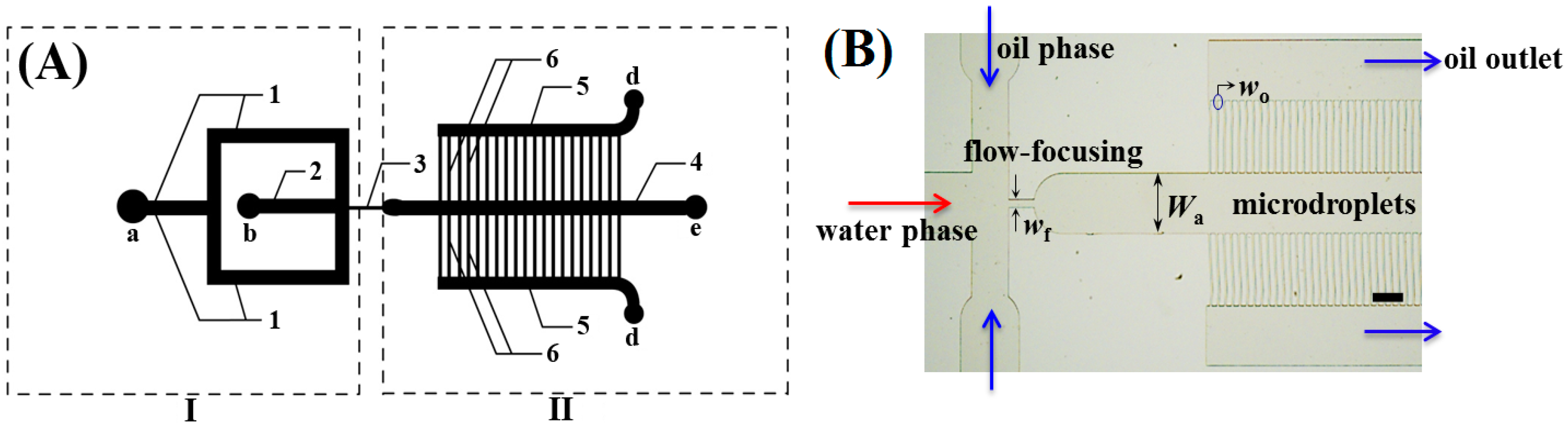
The monodispersed W/O emulsion microdroplets were generated in the PDMS-based flow-focusing microfluidic devices owing to the wettability of the microchannel walls [
33]. The oil phase and water phase were pumped into their corresponding microchannels using syringe pumps. The highly monodispersed microdroplets were obtained at the flow-focusing location, as illustrated in
Figure 2A. Hexadecane with 2.7% (
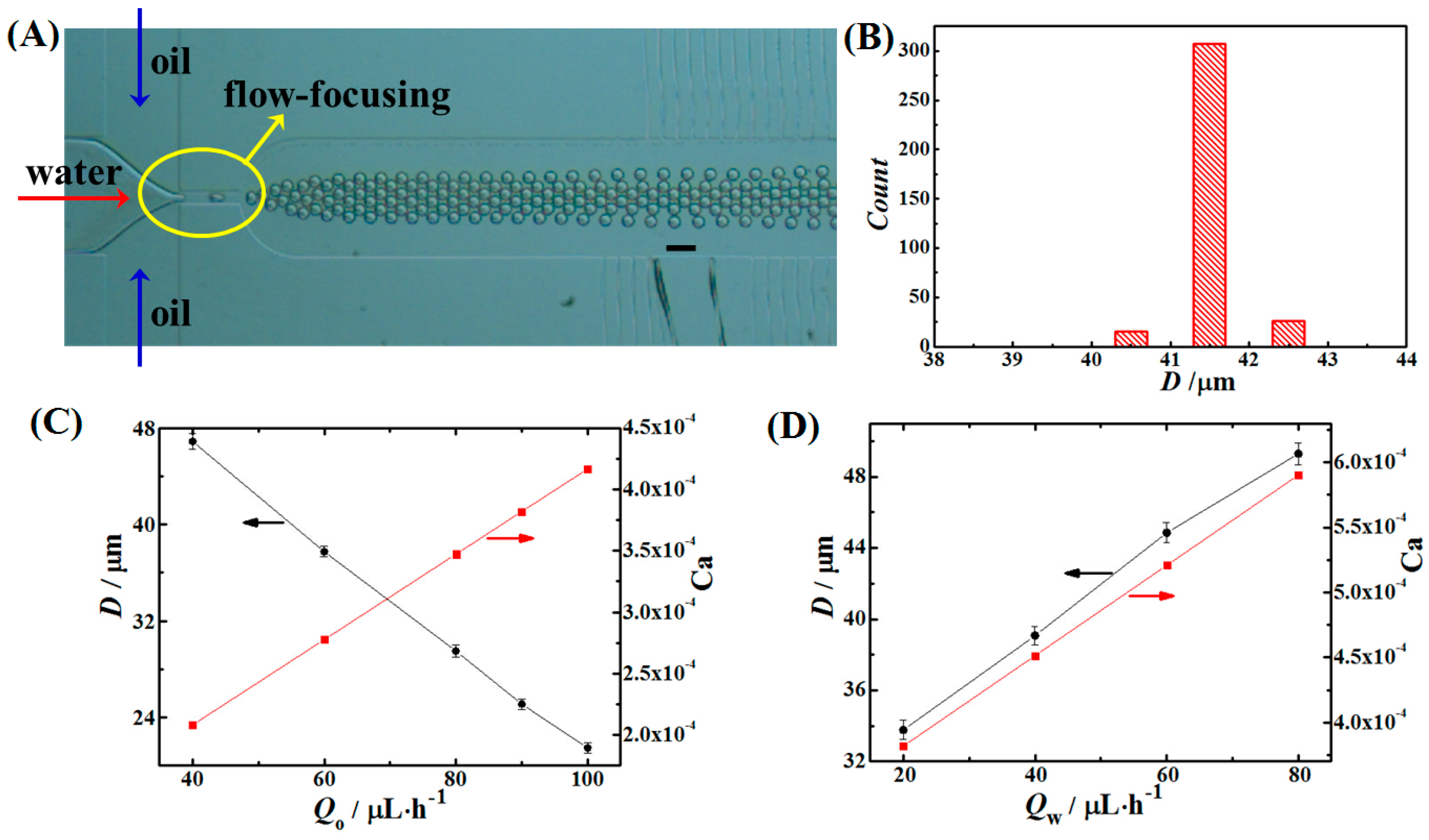
w/v) Span 80 and DI water were used as the oil phase and water phase, respectively. By controlling the two phases volume flow rates and ratios, microdroplets with different diameters in the range of 20–50 μm have been obtained in the devices. The generated microdroplets had a narrow size distribution with the coefficient of variation (CV, %) < 2.0, as shown in
Figure 2B.
The microdroplets fabrication was subjected to several effects such as fluidic flow rates, viscosity, wettability, surface intension and the microchannel geometry [
34]. Generally, in a microfluidic device, the determinative driving forces are interfacial tension force, viscous force and the fluidic channel properties [
35,
36]. The dimensionless number of
Ca (Capillary number) has been used to describe two-phase flow in microchannels, which is defined as:
where η
is the viscosity of the continuous phase (Pa·s),
ν is the average flow velocity (m·s
−1), and σ is the interfacial tension (N·m
−1) between oil and water.
Ca is typically used to explain the microfluidics phenomena, especially for the generation of microdroplets. When
Ca << 1, the interfacial tension is dominant, leading to the formation of droplets [
37].
In our experiment, the fluidic properties were kept constant, the effect of the volume flow rate of each phase on the microdroplets diameter in dripping region [
38,
39,
40] was explored as shown in
Figure 2C,D. The microfluidic device with
wf = 25 μm was used to fabricate monodispersed emulsion droplets.
Qo and
Qw were expressed as the volume flow rate of the oil phase and water phase, respectively. When
Qw was kept constant, the average diameter of the microdroplets decreased as
Qo increased within a range of flow rates, where the value of
Ca increased as well, as demonstrated in
Figure 2C. On the contrary, the average diameter of the spherical microdroplets increased with
Qw and
Ca, when
Qo was constant, as shown in
Figure 2D. The relationship of microdroplets average diameter to
Ca,
Qo and
Qw was also explored in the microfluidic device with
wf = 50 μm in different microdroplets generation regions. The similar curve trend was observed for two devices, revealing each phase flow effect on the microdroplet size.
Over a wide range of flow rates,
Qo in the range of 40–800 μL·h
−1 and
Qw in the range of 10–200 μL·h
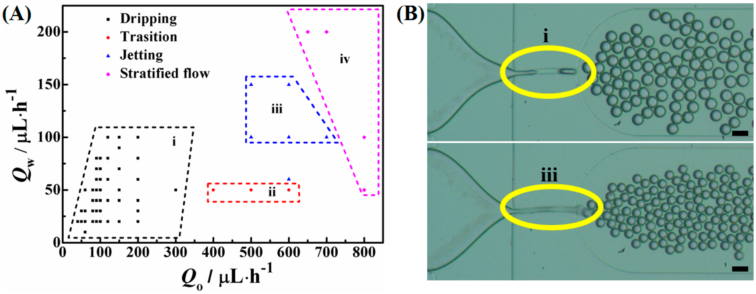
−1, the two-phase (oil-water) droplet-based flow diagram revealed different flow regions in response to the volume flow rates, as shown in
Figure 3. The dripping mode of microdroplet formation was observed at low flow rates. By increasing the flow rates, the microdroplet formation experienced a transition from a dripping to jetting region. Monodispersed microdroplet generation in the dripping (i) and jetting region (iii) were demonstrated in
Figure 3B.
Figure 2.
(A) An optical microscopic image of the microdroplets generation in a PDMS-based flow-focusing microfluidic device. The scale bar is 100 μm. (B) The size distribution of the microdroplets generated in the device (A). The average diameter of the microdroplets was 41.5 μm with the coefficient of variation (CV) 0.7%. In (A) and (B), the highly uniform microdroplets were generated in the device with wf = 50 μm. (C) The microdroplets diameter changed with Ca and Qo in dripping region when Qw was fixed at 20 μL·h−1. Qo was varied from 40 to 100 μL·h−1. (D) The microdroplets diameter changed with Ca and Qw in dripping region when Qo was kept constant at 90 μL·h−1. Qw was varied in the range of 20–80 μL·h−1. In (C) and (D), these monodispersed microdroplets were obtained in the device with wf = 25 μm. The oil phase and water phase were hexadecane with 2.7% (w/v) Span 80 and DI water, respectively.
Figure 3.
(A) Diagram of the microdroplets formation modes as a function of volume flow rates of oil and water phase. The modes were divided into (i) dripping-flow, (ii) transition-flow (from dripping to jetting), (iii) jetting-flow and (iv) stratified-flow; (B) Optical microscopic images of microdroplets generation under dripping (i) and jetting (iii) mode. Scale bars are 50 μm. Qo and Qw were 80 and 20 μL·h−1 for top image of (B), 500 and 150 μL·h−1 for bottom image of (B). Hexadecane with 2.7% (w/v) Span 80 and DI water were used as the oil and water phase, respectively, to generate the emulsion droplets through the same microfluidic device with wf = 25 μm.
3.2. Microdroplet Assembly in the Restricted Microchannels
Monodispersed microdroplets flowed into section II of the microfluidic device after generating, and assembled into close-packed arrangements in the confined main-channel as the continuous phase was squeezed out from the side-channels. The continuous phase flowed through side-channels according to the capillary force and the pressure difference between two ends of the side-channels. In the main-channel, the volume of the channel was constant, and the volume ratio of droplets to the confined channel gradually increased with continuous phase flowing away. The microdroplets then rearranged themselves in an ordered way to minimize the free energy of the system.
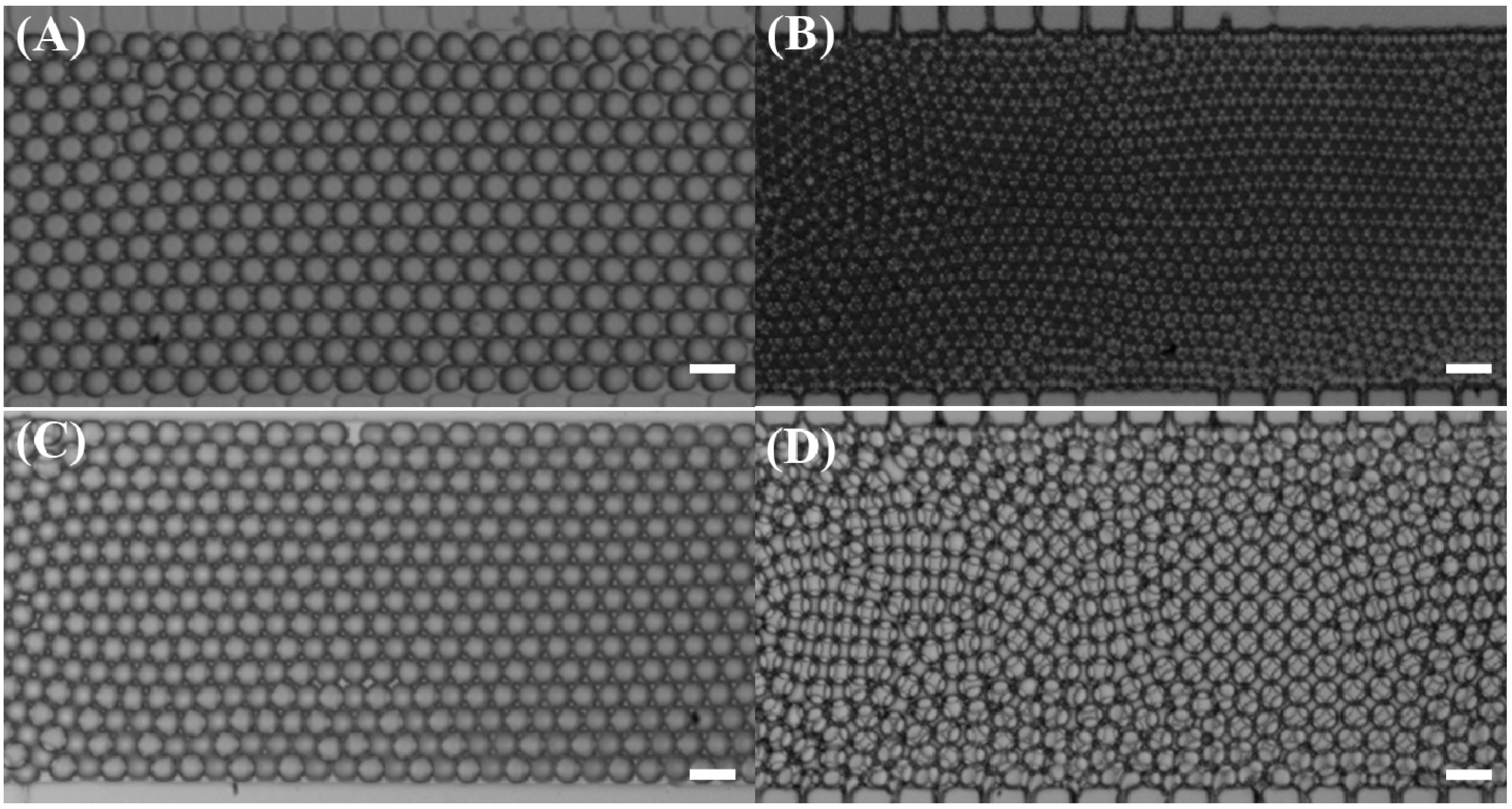
The monodispersed microdroplets self-assembled into 2D and 3D configurations in the confined channel of the microfluidic devices. Well-ordered close-packed single-layer hexagonal arrangements and double-layer square or hexagonal configurations have been observed in a wide range of flow rates at different microfluidic devices, as shown in
Figure 4. It is well known that the spherical particles self-assemble into close-packed arrangements when the volume fraction of particles in a confined volume increases in order to minimize the free energy. In a microfluidic device, both continuous and dispersed phase flow can be controlled; therefore, the volume fraction can be controlled by varying flow rates and channel geometry. On the other hand, the droplet size and shearing force induced by fluidic flow plays a significant role on the droplets packing. Several parameters normally co-determined the microdroplet assembly configurations. In this report, we investigated the effects of the location of the droplets in the main-channel, two phase volume flow rates, droplet size and the water phase properties on the droplets assembly configurations in the microfluidic channel.
Figure 4.
Optical microscopic images of the microdroplets assembly configurations at various flow rates and at different microfluidic devices with (A) and (C) in close-packed single-layer mode, (B) and (D) in close-packed double-layer mode. In (A) and (B), the microdroplets were generated in the same microfluidic device with wf = 25 μm; in (C) and (D), the microdroplets were formed in the same microfluidic device with wf = 50 μm. In (A) and (C), the microdroplets were generated in dripping region; in (B) and (D), the microdroplets were formed under jetting mode. Qo and Qw were 90 and 20 μL·h−1 (A), 600 and 60 μL·h−1 (B), 800 and 100 μL·h−1 (C), 2000 and 400 μL·h−1 (D). The oil phase and water phase were all hexadecane with 2.7% (w/v) Span80 and DI water. Scale bars are 50 μm.
3.2.1. Microdroplet Assembly along the Confinement Main-Channel
When the flow rate and ratio were controlled in a specific range, we found that different droplet configurations (single-layer and double-layer) were obtained at the same time along the same main-channel but at different locations. As shown in
Figure 5, the produced microdroplets experienced from random arrangements to close-packed single-layer and then double-layer configurations gradually along the main assembly channel. As the oil phase was squeezed into the side-channels, the volume fraction of water droplets to oil phase increased. Here, the volume fraction (Φ
vol) was defined as the volume ratio of the droplets to the assembly confinement microchannel, which was equal to the total volume of oil and water phase. The microdroplets flowed directly into section II after generating, and started to accumulate into random configurations (close pack without ordering) when Φ
vol was more than 0.19. As Φ
vol increased to 0.27, the droplets started packing into well-ordered structures in one layer. When Φ
vol approached 0.53, the droplets further packed into two-layer configurations. As the volume fraction further increased, the droplets fully filling the main-channel with oil phase only existed among the curved interface between droplets. If the value of Φ
vol increased further, the droplets would be even well-packed but deformed at the end. The on-line packing of these microdroplets was mainly attributed to the volumetric effect. The flowing of oil phase through side-channels was according to the capillarity and the pressure difference. Because the surface of the microchannel was wetting to the oil phase, as soon as the oil phase came into contact with the side-channels area, the oil phase was imbibed into them owing to the capillary force. The exact flow of the oil phase through the side-channels corresponded to the side-channel number, size and pressure difference between the entrance and exit.
Movie S1 in the supplementary information showed a complete process of the microdroplets generation and assembly along the main-channel. In the next sections, the named assembly configurations were all referred to the final equilibrium states in the end of the main-channel.
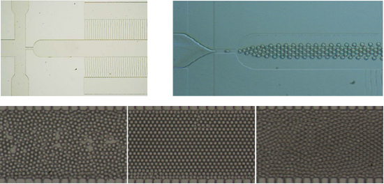
Figure 5.
Series of the optical microscopic images of the monodispersed microdroplets assembly configurations at different locations along the same main-channel: (A) random arrangement, (B) close-packed single-layer configuration and (C) close-packed double-layer configuration. The characteristic size of the microfluidic device: wf = 25 μm, dc = 40 μm and Wa = 400 μm. Hexadecane with 2.7% (w/v) Span 80 and DI water were used as the oil phase and water phase, respectively. Microdroplets were produced under jetting mode, with Qo = 600 μL·h−1 and Qw = 100 μL·h−1. Scale bars are 50 μm.
3.2.2. Effect of Volume Flow Rates on the Microdroplets Assembly
In the microfluidic device, the hydrodynamic force changed with the fluidic flow rates, which, in the end, affected the assembling dynamics of the droplets. By simply changing the two phase flow rates, the single-layer, double-layer and multiple-layer close-packed arrangements were obtained in the confined microchannels. It was found that, in the dripping region, the microdroplets could pack into ordered single-layer lattices along the surface even at the volume fraction (the ratio of total droplets volume to the confined channel volume) of less than 0.5. While in the jetting region, microdroplets generally assembled into close-packed double or multiple layers without experiencing the well-ordered single-layer pattern. This might be due to the stable laminar fluidic flow in the confined channel. The monodispersed droplets tended to rearrange orderly along the flow gradient.
We took the microdroplets assembly in the microfluidic device with the characteristic size of
wf = 25 μm,
dc = 40 μm and
Wa = 400 μm as an example to explore the effect of
Qo and
Qw on the microdroplets assembly.
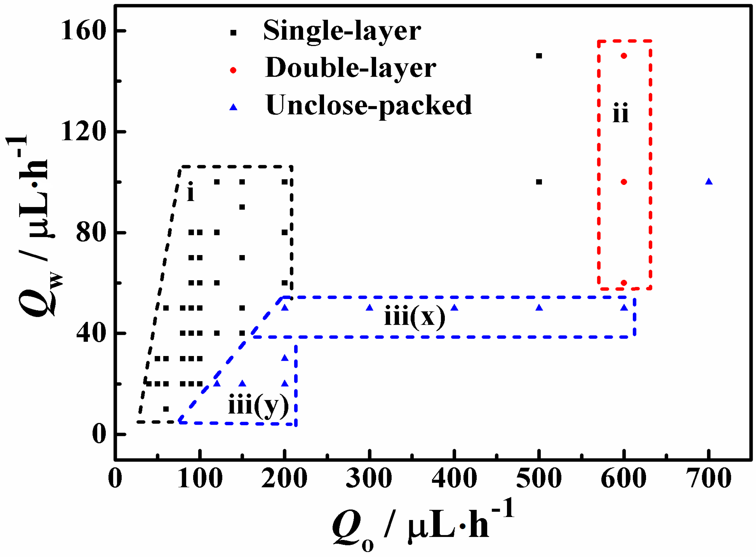
Figure 6 illustrated the microdroplets assembly configurations corresponding to the two phase volume flow rates. When the microdroplets formation was located in the transition region (as shown in
Figure 3: area ii), it was difficult for the microdroplets to arrange into ordered patterns owing to the instability of the microdroplets production and fluidic flowing, as shown in
Figure 6 iii(x) area. Monodispersed microdroplets were close-packed into well-ordered single-layer patterns at low flow rates for two reasons: the flow was stable to achieve ordered assembling instead of randomly arranging, and the volume fraction was not big enough for further packing according to the gentle flow. Whereas at higher flow rates, microdroplets were able to assemble into close-packed well-ordered double-layer configurations resulted from the dramatically increased volume fraction, which led to the rapid accumulation to high density packing. In addition, in the
Figure 6 iii(y) area, there were no ordered arrangements observed because of the low droplet generation frequency.
Figure 6.
Diagram of the microdroplets assembly configurations as a function of two phase flow rates. The configurations were divided into: (i) close-packed well-ordered single-layer configurations, (ii) close-packed highly-ordered double-layer configurations and (iii) unclose-packed (loose or random) configurations. The microdroplets were generated in either dripping or jetting region at different flow rates. The dimensions of the flow-focusing microfluidic device were: wf = 25 μm, dc = 40 μm and Wa = 400 μm. Hexadecane with 2.7% (w/v) Span 80 and DI water were used as the oil phase and water phase, respectively.
In
Figure 6, there were more data points found in the bottom-left area than top-right area because of the stable droplet generation and fluidic flow at low flow rates rather than high flow rates. The fluidic flow rate not only affected the capability of creating numerous monodispersed microdroplets at a particular period of time but also determined the microdroplet assembly configurations. The precise controllability of fluidic flow in the device is critical for the microdroplets assembling into ordered configurations in the confined microchannels.
3.2.3. Microdroplets Size Effect on the Assembly Configurations
The crystalline lattice of droplet packing model in theory for predicting high density monodispersed droplets assembly patterns by controlling the confined channel depth or droplet size has been demonstrated by Lee
et al. [
10]. By changing only the depth of the microchannel (
dc) relative to a given monodispersed droplet diameter (
D), predictable close-packed single-, double- or multiple-layer lattices could be obtained. Hereafter, the ratio of the microchannel depth (
dc) to droplet size (
D) was referred to as
dc/
D. Miller index notation was employed to describe liquid crystallographic planes: namely (111), (110) and (100) crystal orientations.
Figure 7 presented predictable close-packed well-ordered colloidal crystal configurations, expecting monodispersed droplets assembly corresponding to
dc/
D values.
Figure 7.
Diagram of droplets close-packing configurations corresponding to dc/D. The top-left insertion is the schematic drawing of droplets pattern in Miller lattice orientations. The images of (A), (B) and (C) were single-layer hexagonal (111), double-layer square (100) and double-layer hexagonal (111) configurations, respectively. Scale bars are 50 μm. Here, the microfluidic device was: wf = 25 or 50 μm, dc = 40 μm, Wa = 400 μm. Hexadecane with 2.7% (w/v) Span80 and DI water were used as the oil phase and water phase, respectively.
Monodispersed microdroplets were produced in the microfluidic device with
wf = 25 or 50 μm,
dc = 40 μm and
Wa = 400 μm.
dc/
D value was dynamically controlled by adjusting droplet size for a given channel depth (40 μm). The well-ordered close-packed assembly configurations in common Miller index configurations were obtained at different
dc/
D which were 1.11, 1.67 and 1.90 for (A), (B) and (C) in
Figure 7, respectively. Single-layer hexagonal configuration was observed for 36 μm droplets assembled in the 40 μm deep channel with
dc/
D = 1.11 (A). A
dc/
D value of 1.67 (24 μm droplets) favored double-layer square configuration (B). A
dc/
D value of 1.90 was beneficial for 21 μm droplets to assemble in double-layer hexagonal pattern (C).
Various droplet assembly configurations in the confined channel were statistically analyzed. It was found that, in the range of dc/D = 0.9–1.5, the monodispersed droplets would assemble into close-packed single-layer hexagonal configurations, and the corresponding microdroplets generation was mostly in the dripping region. Whereas, when dc/D was in the range of 1.8–2.1, monodispersed droplets would self-organize into close-packed double-layer hexagonal pattern in (111) orientation at high flow rates in the jetting region. When dc/D was ranged from 1.5 to 1.8, the droplet arrangements would experience transition from close-packed single-layer hexagonal (111) to double-layer square (100) configurations. Liquid droplet assembly would be better suitable for confined geometries due to their flexible mobility and ease of deformation compared to solid colloidal particles.
3.3.4. Effect of Fluids on Droplet Generation and Assembly
Different fluidic materials have also been investigated to explore the effect of the fluidic properties on the assembly configurations for the future selection of functional materials for different applications. Polymerizable aqueous solutions composed of NIPAM monomer (6 wt %–25 wt %), MBA cross-linker (1 wt
%–3 wt
%) and I 2959 photoinitiator (0.2 wt
%–3 wt
%) were used as the water phases. The oil phases were hexadecane with Span 80 or mineral oil contained ABIL EM 90. The same microfluidic device was used. Similar phenomenon has been observed for monodispersed droplets formation and assembly, as shown in
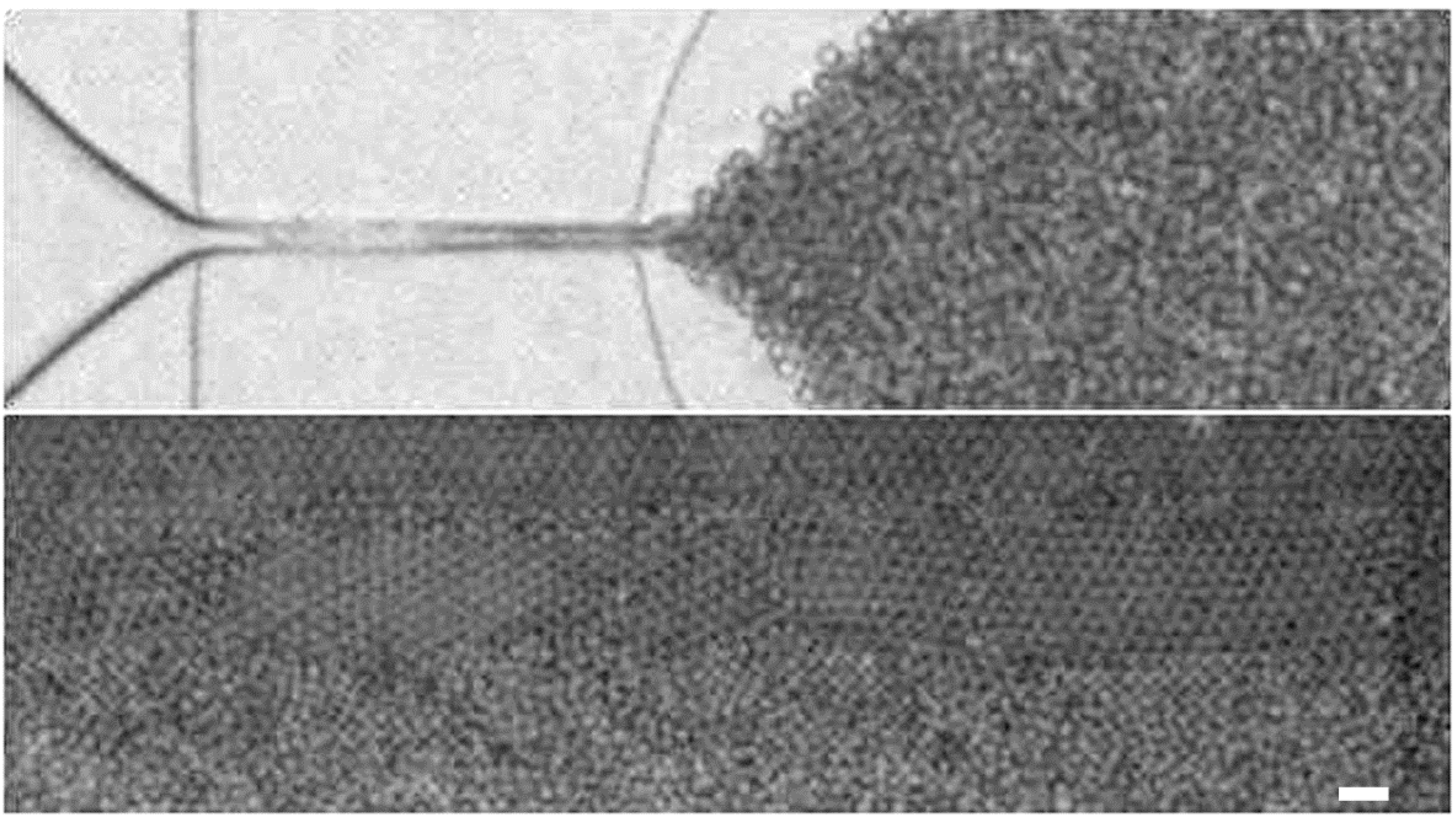
Figure S3. Differently, for the fluidic system of NIPAM aqueous solution and hexadecane with Span 80 organic solution, in a range of flow rates, much smaller microdroplets were produced and then rapidly assembled into ordered arrangement in multiple-layer pattern.
As an example, 15 wt
% NIPAM photocurable aqueous solution mixed with 3.0 wt
% MBA and 1.5 wt % I 2959 was used as the water phase and hexadecane contained 2.7% (
w/v) Span80 was used as the oil phase. Interestingly, as shown in
Figure 8, we obtained the monodispersed droplets with the diameter of only 7 μm at
Qo = 150 μL·h
−1 and
Qw = 20 μL·h
−1. However, at the same flow rates in the same device, the droplets with diameter of 28 μm were obtained using hexadecane with 2.7% (
w/v) Span 80 and DI water as oil and water phase. The close-packed structure was partially in multiple-layer configuration according to the smaller droplet size. This might attribute to the effect of the interfacial tension between the two immiscible oil-water systems. The interfacial tension of the 15 wt
% NIPAM aqueous solution (3.0 wt
% MBA and 1.5 wt
% I 2959)/2.7% (
w/v) Span 80 hexadecane solution was 1.62 mN·m
−1, which was ten times smaller than 15.0 mN·m
−1 for the DI water/2.7% (
w/v) Span 80 hexadecane solution. With lower interfacial tension, the hydrodynamic force was relatively more prominent, which could induce quicker and smaller droplets formation, and then more layers of droplets arrangement. In the future, the microdroplets composed of photocurable NIPAM aqueous solution could be on-line polymerized into functional microparticles, which could be potentially applied as valves, actuators or sensors.
Figure 8.
Optical microscopic images of the microdroplets generation and assembly multiple-layer configuration of the functional fluidic material system. The water phase was 15 wt % NIPAM aqueous solution mixed with 3.0 wt % MBA and 1.5 wt % I 2959, and the oil phase was hexadecane contained 2.7% (w/v) Span80. Qo and Qw were 150 and 20 μL·h−1, respectively. The microfluidic device dimensions were wf = 25 μm, dc = 40 μm and Wa = 400 μm. The scale bar is 50 μm.


