
Design and Fabrication of the Split Ring Resonator Shaped Two-Element MIMO Antenna with Multiple-Band Operation for WiMAX/5G/Zigbee/Wi-Fi Applications
 , ,
, ,  , ,
, ,
Abstract
:1. Introduction
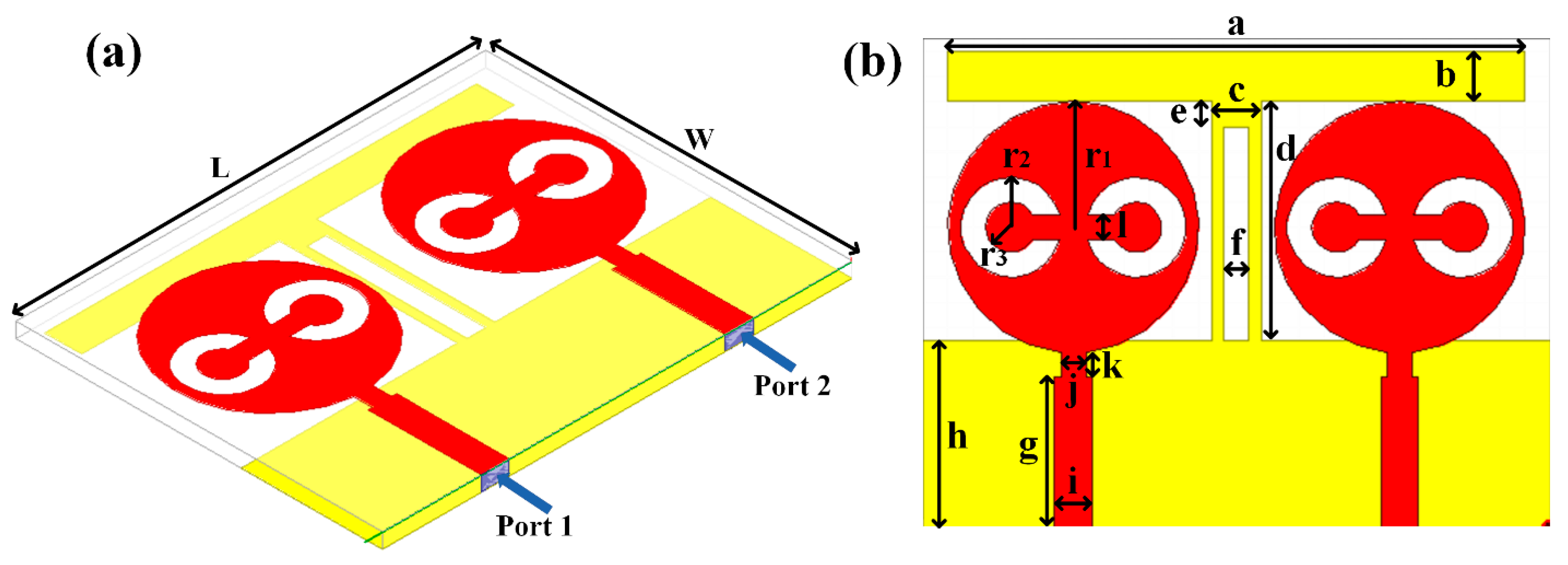
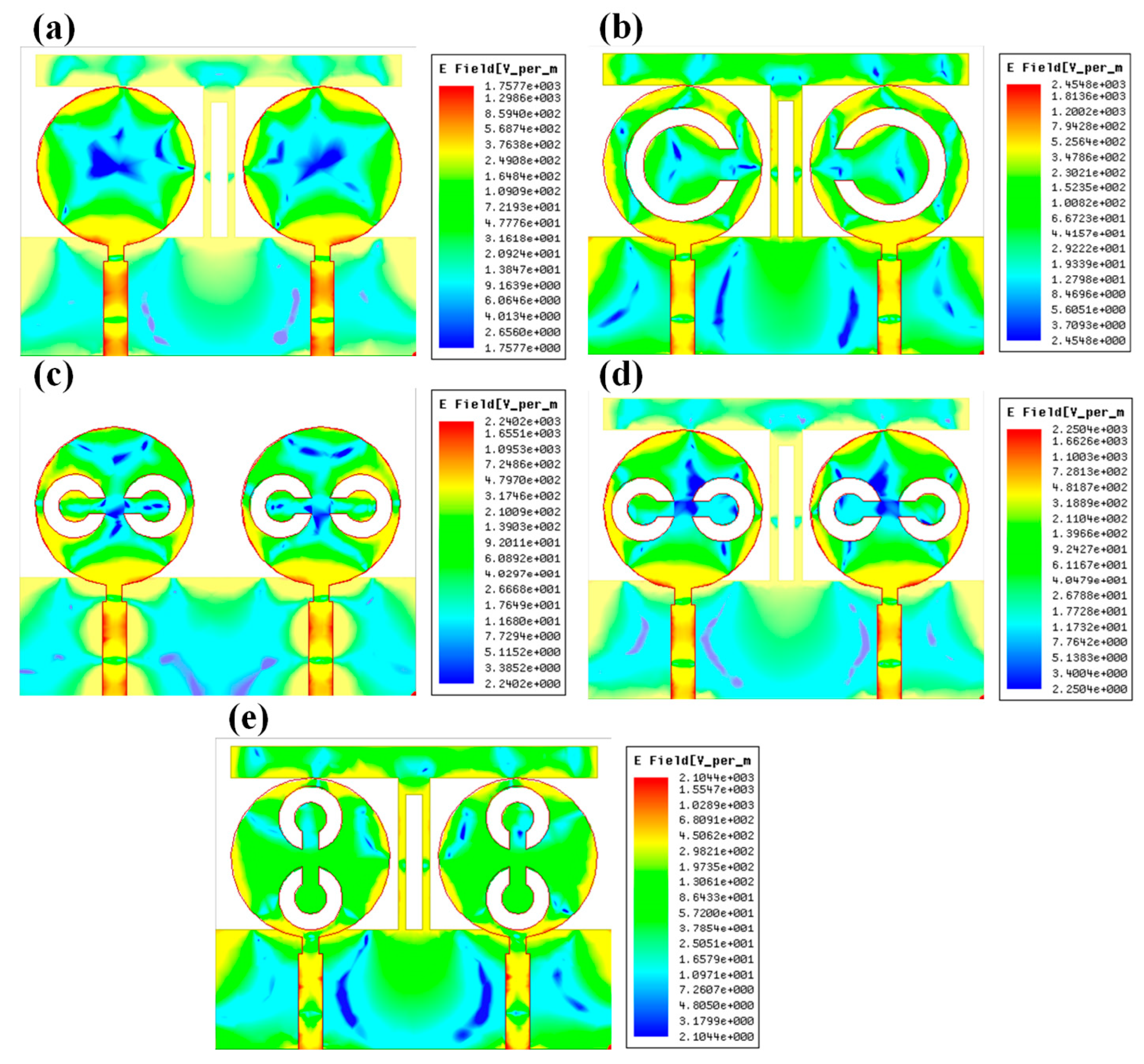
2. Split Ring Resonator Loaded MIMO Antenna Structure
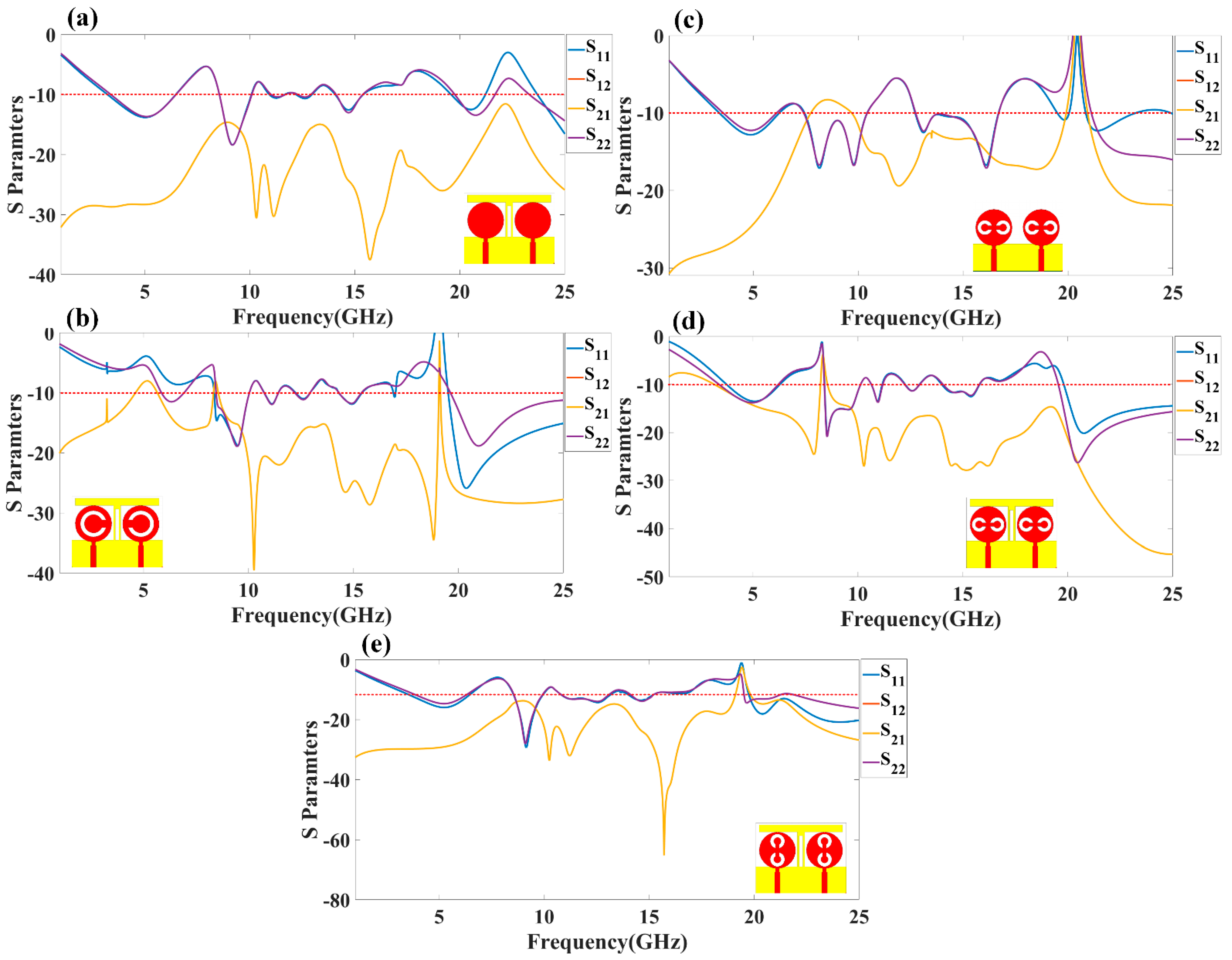
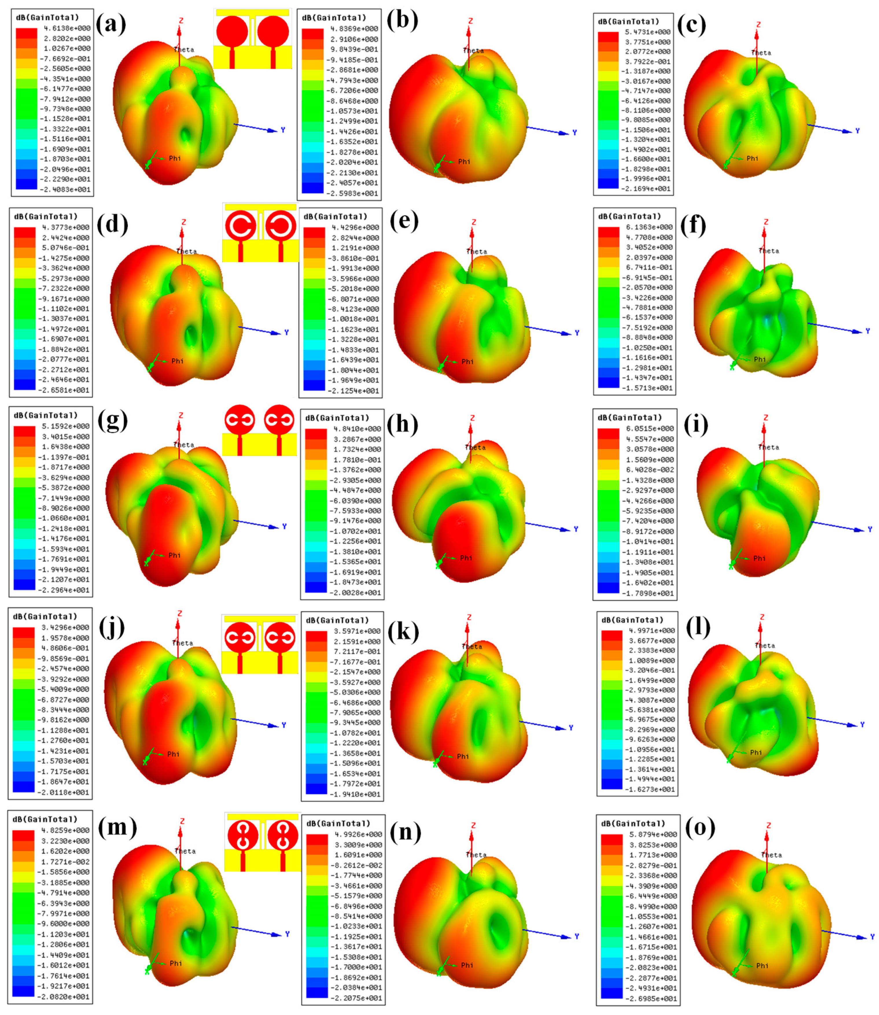
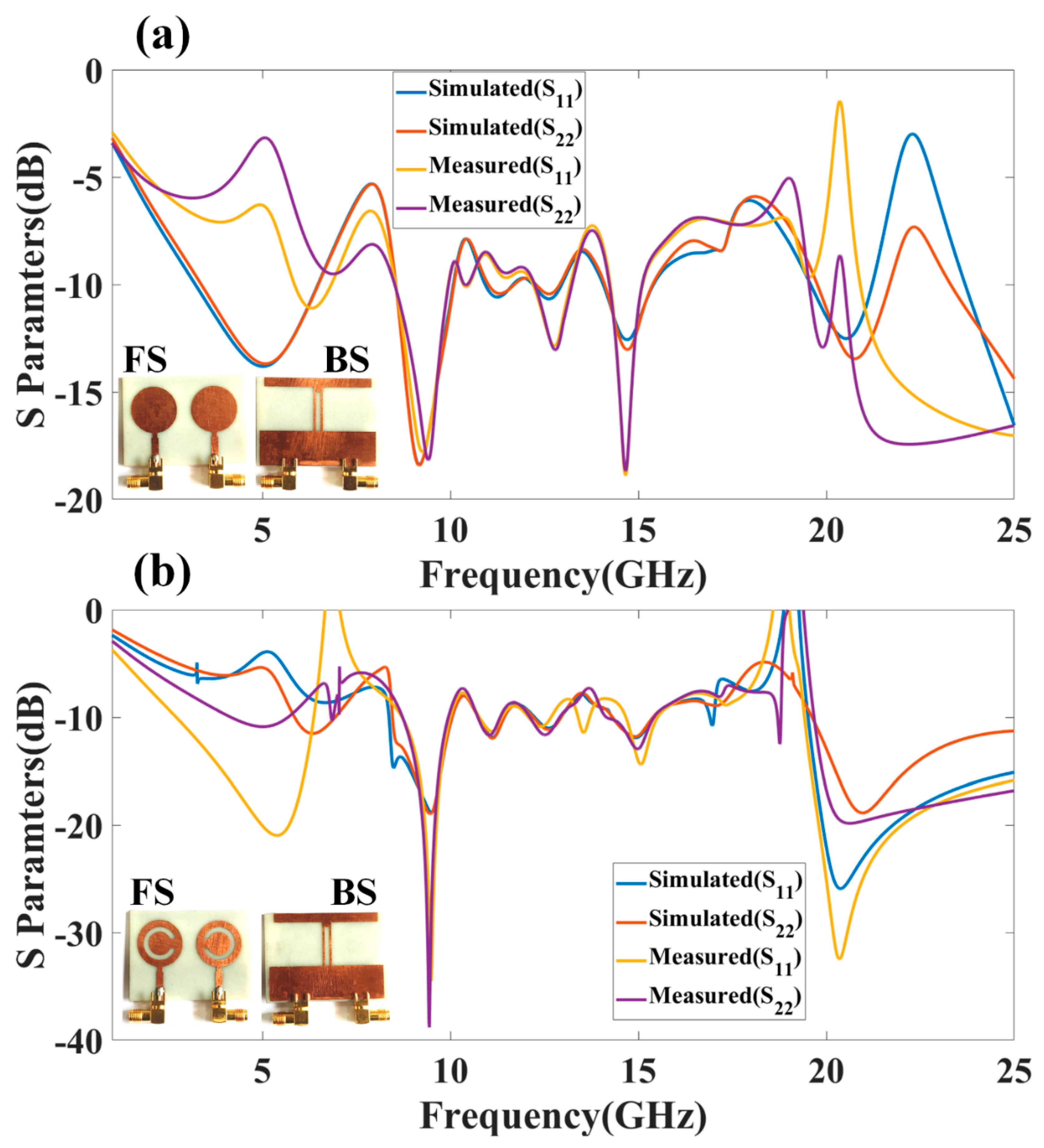
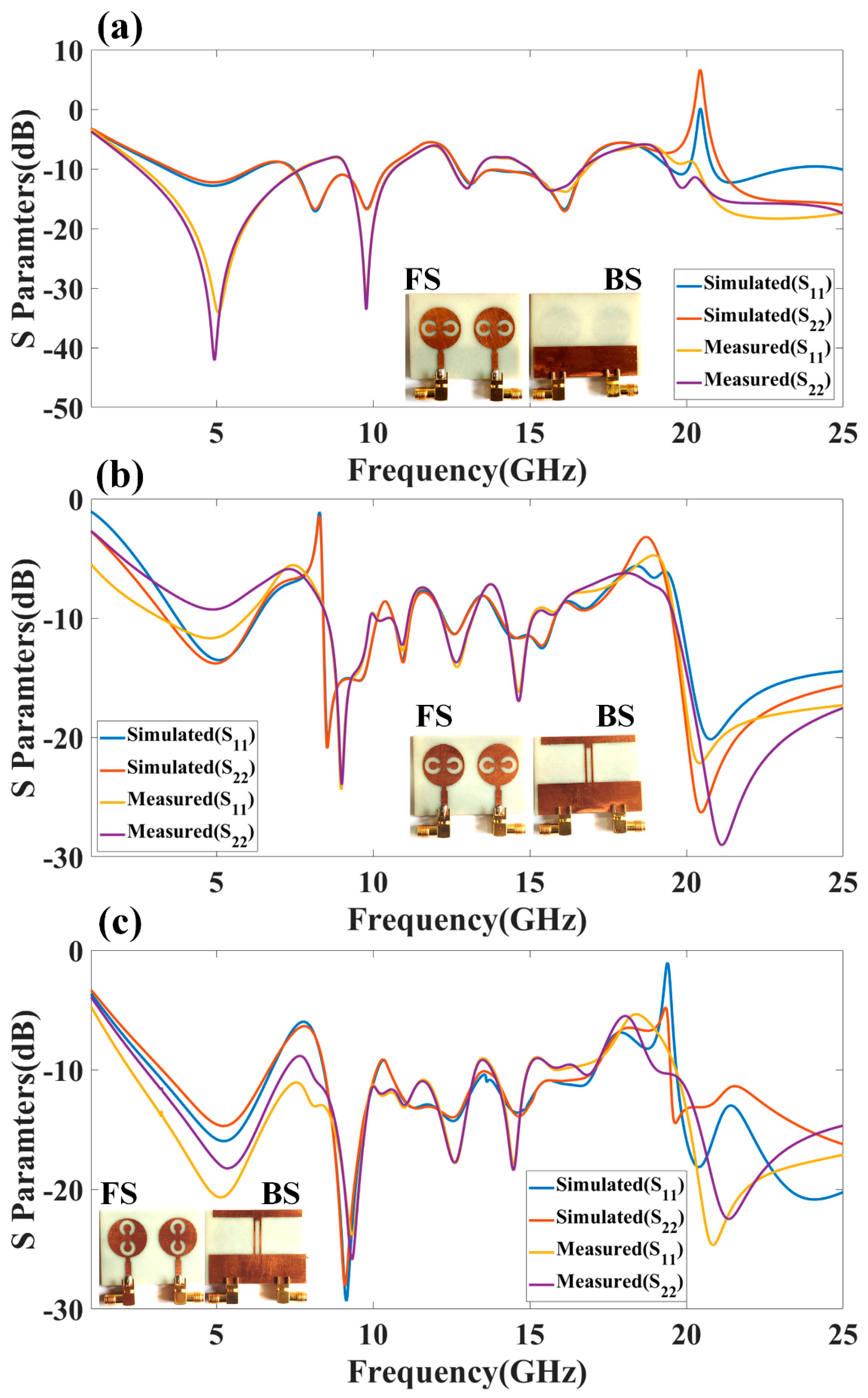
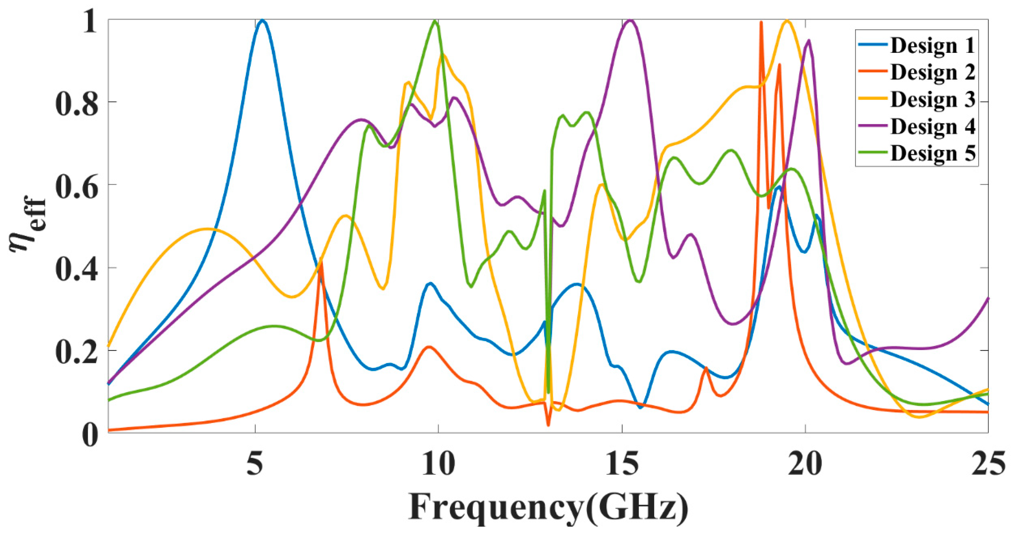
3. Results and Discussion
4. Conclusions
Author Contributions
Funding
Data Availability Statement
Acknowledgments
Conflicts of Interest
References
- Fathima, N.; Nayana, K.S.; Ali, T.; Biradar, R.C. A miniaturized slotted ground fractal Koch multiband antenna for wireless applications. In Proceedings of the RTEICT 2017-2nd IEEE International Conference on Recent Trends in Electronics, Information and Communication Technology, Bangalore, India, 19–20 May 2017; pp. 251–255. [Google Scholar] [CrossRef]
- Balani, W.; Sarvagya, M.; Ali, T.; Pai, M.; Anguera, J.; Andujar, A.; Das, S. Design Techniques of Super-Wideband Antenna–Existing and Future Prospective. IEEE Access 2019, 7, 141241–141257. [Google Scholar] [CrossRef]
- JPark, J.-D.; Rahman, M.; Chen, H.N. Isolation Enhancement of Wide-Band MIMO Array Antennas Utilizing Resistive Loading. IEEE Access 2019, 7, 81020–81026. [Google Scholar] [CrossRef]
- Malekpour, N.; Honarvar, M.A. Design of high-isolation compact MIMO antenna for UWB application. Prog. Electromagn. Res. C 2016, 62, 119–129. [Google Scholar] [CrossRef] [Green Version]
- Alharbi, A.G.; Sorathiya, V. Ultra-Wideband Graphene-Based Micro-Sized Circular Patch-Shaped Yagi-like MIMO Antenna for Terahertz Wireless Communication. Electronics 2022, 11, 1305. [Google Scholar] [CrossRef]
- Ren, J.; Hu, W.; Yin, Y.; Fan, R. Compact Printed MIMO Antenna for UWB Applications. IEEE Antennas Wirel. Propag. Lett. 2014, 13, 1517–1520. [Google Scholar] [CrossRef]
- Dave, K.; Sorathiya, V.; Lavadiya, S.P.; Patel, S.K.; Dhankecha, U.; Swain, D.; Faragallah, O.S.; Eid, M.M.A.; Rashed, A.N.Z. Graphene-based double-loaded complementary split ring resonator (CSRR) slotted MIMO patch antenna for spectroscopy and imaging THz applications. Appl. Phys. A 2022, 128, 656. [Google Scholar] [CrossRef]
- Jensen, M.; Wallace, J. A Review of Antennas and Propagation for MIMO Wireless Communications. IEEE Trans. Antennas Propag. 2004, 52, 2810–2824. [Google Scholar] [CrossRef] [Green Version]
- Saadh, A.M.; Ashwath, K.; Ramaswamy, P.; Ali, T.; Anguera, J. A uniquely shaped MIMO antenna on FR4 material to enhance isolation and bandwidth for wireless applications. AEU-Int. J. Electron. Commun. 2020, 123, 153316. [Google Scholar] [CrossRef]
- Li, Y.; Li, W.; Yu, W. A multi-band/UWB MIMO/diversity antenna with an enhanced isolation using radial stub loaded resonator. Appl. Comput. Electromagn. Soc. J. 2013, 28, 8–20. [Google Scholar]
- Zhao, Y.; Li, Y.; Shi, W.; Yu, W. Mutual coupling reduction between patch antenna and microstrip transmission line by using defected isolation wall. Appl. Comput. Electromagn. Soc. J. 2019, 34, 1. [Google Scholar]
- Aw, M.S.; Ashwath, K.R.; Ali, T. A compact two element MIMO antenna with improved isolation for wireless applications. J. Instrum. 2019, 14, P06014. [Google Scholar] [CrossRef]
- BharathiDevi, B.; Kumar, J. Small frequency range discrete bandwidth tunable multiband MIMO antenna for radio/LTE/ISM-2.4 GHz band applications. AEU-Int. J. Electron. Commun. 2021, 144, 154060. [Google Scholar] [CrossRef]
- Lavadiya, S.P.; Sorathiya, V.; Kanzariya, S.; Chavda, B.; Naweed, A.; Faragallah, O.S.; Eid, M.M.A.; Rashed, A.N.Z. Low profile multiband microstrip patch antenna with frequency reconfigurable feature using PIN diode for S, C, X, and Ku band applications. Int. J. Commun. Syst. 2022, 35, 9. [Google Scholar] [CrossRef]
- Hasan, M.; Islam, M.T.; Samsuzzaman; Baharuddin, M.H.; Soliman, M.S.; Alzamil, A.; Abu Sulayman, I.I.M.; Islam, S. Gain and isolation enhancement of a wideband MIMO antenna using metasurface for 5G sub-6 GHz communication systems. Sci. Rep. 2022, 12, 9433. [Google Scholar] [CrossRef]
- Megahed, A.A.; Abdelazim, M.; Abdelhay, E.H.; Soliman, H.Y.M. Sub-6 GHz Highly Isolated Wideband MIMO Antenna Arrays. IEEE Access 2022, 10, 19875–19889. [Google Scholar] [CrossRef]
- Jabeen, S.; Khan, Q.U. An integrated MIMO antenna design for Sub-6 GHz & millimeter-wave applications with high isolation. AEU-Int. J. Electron. Commun. 2022, 153, 154247. [Google Scholar] [CrossRef]
- Sarkar, D.; Srivastava, K.V. A compact four-element MIMO/diversity antenna with enhanced bandwidth. IEEE Antennas Wirel. Propag. Lett. 2017, 16, 2469–2472. [Google Scholar] [CrossRef]
- Anitha, R.; Vinesh, P.V.; Prakash, K.C.; Mohanan, P.; Vasudevan, K. A Compact Quad Element Slotted Ground Wideband Antenna for MIMO Applications. IEEE Trans. Antennas Propag. 2016, 10, 4550–4553. [Google Scholar] [CrossRef]
- Pandit, S.; Mohan, A.; Ray, P. A compact four-element MIMO antenna for WLAN applications. Microw. Opt. Technol. Lett. 2018, 60, 289–295. [Google Scholar] [CrossRef]
- Azarm, B.; Nourinia, J.; Ghobadi, C.; Majidzadeh, M. Highly isolated dual band stop two-element UWB MIMO antenna topology for wireless communication applications. J. Instrum. 2019, 14, P10036. [Google Scholar] [CrossRef]
- Hatami, N.; Nourinia, J.; Ghoabdi, C.; Majidzadeh, M.; Azarm, B. High inter-element isolation and WLAN filtering mechanism: A compact MIMO antenna scheme. AEU-Int. J. Electron. Commun. 2019, 109, 43–54. [Google Scholar] [CrossRef]
- Li, H.; Shi, D.; Wang, W.; Liao, D.; Gadekallu, T.R.; Yu, K. Secure routing for LEO satellite network survivability. Comput. Netw. 2022, 211, 109011. [Google Scholar] [CrossRef]
- Wang, W.; Xu, H.; Alazab, M.; Gadekallu, T.R.; Han, Z.; Su, C. Blockchain-Based Reliable and Efficient Certificateless Signature for IIoT Devices. IEEE Trans. Ind. Inform. 2021, 18, 7059–7067. [Google Scholar] [CrossRef]
- Ding, F.; Zhu, G.; Alazab, M.; Li, X.; Yu, K. Deep-Learning-Empowered Digital Forensics for Edge Consumer Electronics in 5G HetNets. IEEE Consum. Electron. Mag. 2020, 11, 42–50. [Google Scholar] [CrossRef]
- Naqvi, S.I.; Hussain, N.; Iqbal, A.; Rahman, M.; Forsat, M.; Mirjavadi, S.S.; Amin, Y. Integrated LTE and Millimeter-Wave 5G MIMO Antenna System for 4G/5G Wireless Terminals. Sensors 2020, 20, 3926. [Google Scholar] [CrossRef] [PubMed]
- Dong, Y.; Liu, P.; Yu, D.; Li, G.; Tao, F. Dual-Band Reconfigurable Terahertz Patch Antenna with Graphene-Stack-Based Backing Cavity. IEEE Antennas Wirel. Propag. Lett. 2016, 15, 1541–1544. [Google Scholar] [CrossRef]
- Li, J.; Zhang, X.; Wang, Z.; Chen, X.; Chen, J.; Li, Y.; Zhang, A. Dual-Band Eight-Antenna Array Design for MIMO Applications in 5G Mobile Terminals. IEEE Access 2019, 7, 71636–71644. [Google Scholar] [CrossRef]
- Liu, X.-L.; Wang, Z.-D.; Yin, Y.-Z.; Ren, J.; Wu, J.-J. A Compact Ultrawideband MIMO Antenna Using QSCA for High Isolation. IEEE Antennas Wirel. Propag. Lett. 2014, 13, 1497–1500. [Google Scholar] [CrossRef]
- Chae, S.H.; Oh, S.-K.; Park, S.-O. Analysis of Mutual Coupling, Correlations, and TARC in WiBro MIMO Array Antenna. IEEE Antennas Wirel. Propag. Lett. 2007, 6, 122–125. [Google Scholar] [CrossRef]
- Zahoor, M.; Dou, Z.; Shah, S.; Khan, I.; Ayub, S.; Gadekallu, T.R. Pilot Decontamination Using Asynchronous Fractional Pilot Scheduling in Massive MIMO Systems. Sensors 2020, 20, 6213. [Google Scholar] [CrossRef]
- Babu, K.V.; Anuradha, B. Design of inverted L-shape & ohm symbol inserted MIMO antenna to reduce the mutual coupling. AEU-Int. J. Electron. Commun. 2019, 105, 42–53. [Google Scholar] [CrossRef]
- Babu, K.V.; Anuradha, B.; Das, S. Design & analysis of a dual-band MIMO antenna to reduce the mutual coupling. J. Instrum. 2019, 14, P09023. [Google Scholar] [CrossRef]
- Krishna, C.M.; Das, S.; Lakrit, S.; Lavadiya, S.; Madhav, B.T.P.; Sorathiya, V. Design and analysis of a super wideband (0.09–30.14 THz) graphene based log periodic dipole array antenna for terahertz applications. Optik 2021, 247, 167991. [Google Scholar] [CrossRef]
- Radhi, A.H.; Nilavalan, R.; Wang, Y.; Al-Raweshidy, H.S.; Eltokhy, A.A.; Ab Aziz, N. Mutual coupling reduction with a wideband planar decoupling structure for UWB–MIMO antennas. Int. J. Microw. Wirel. Technol. 2018, 10, 1143–1154. [Google Scholar] [CrossRef] [Green Version]
- Rajkumar, S.; Amala, A.A.; Selvan, K. Isolation improvement of UWB MIMO antenna utilising molecule fractal structure. Electron. Lett. 2019, 55, 576–579. [Google Scholar] [CrossRef]
- Khan, A.A.; Naqvi, S.A.; Khan, M.S.; Ijaz, B. Quad port miniaturized MIMO antenna for UWB 11 GHz and 13 GHz frequency bands. AEU-Int. J. Electron. Commun. 2021, 131, 153618. [Google Scholar] [CrossRef]
- Chouhan, S.; Panda, D.K.; Kushwah, V.S. Modified circular common element four-port multiple-input-multiple-output antenna using diagonal parasitic element. Int. J. RF Microw. Comput. Eng. 2018, 29, e21527. [Google Scholar] [CrossRef]
- Malviya, L.; Chouhan, S. Multi-cut four-port shared radiator with stepped ground and diversity effects for WLAN application. Int. J. Microw. Wirel. Technol. 2019, 11, 1044–1053. [Google Scholar] [CrossRef]
- Jaglan, N.; Gupta, S.D.; Thakur, E.; Kumar, D.; Kanaujia, B.K.; Srivastava, S. Triple band notched mushroom and uniplanar EBG structures based UWB MIMO/Diversity antenna with enhanced wide band isolation. AEU-Int. J. Electron. Commun. 2018, 90, 36–44. [Google Scholar] [CrossRef]
- Chouhan, S.; Malviya, L. Four-port shared rectangular radiator with defected ground for wireless application. Int. J. Commun. Syst. 2020, 33, e4356. [Google Scholar] [CrossRef]
- MoradiKordalivand, A.; Rahman, T.A.; Khalily, M. Common Elements Wideband MIMO Antenna System for WiFi/LTE Access-Point Applications. IEEE Antennas Wirel. Propag. Lett. 2014, 13, 1601–1604. [Google Scholar] [CrossRef]
- Moradikordalivand, A.; Leow, C.Y.; Rahman, T.A.; Ebrahimi, S.; Chua, T.H. Wideband MIMO antenna system with dual polarization for WiFi and LTE applications. Int. J. Microw. Wirel. Technol. 2015, 8, 643–650. [Google Scholar] [CrossRef]
- Chithradevi, R.; Sreeja, B.S. A compat UWB MIMO antenna with high isolation and low correlation for wireless applications. In Proceedings of the 2017 IEEE International Conference on Antenna Innovations & Modern Technologies for Ground, Aircraft and Satellite Applications (iAIM), Bangalore, India, 24–26 November 2017; pp. 1–4. [Google Scholar] [CrossRef]


| Parameter | a | b | c | d | e | f | g | h | i | j | k | l | W | L | r1 | r2 | r3 |
| Values (mm) | 46 | 4 | 4 | 19 | 2 | 2 | 12 | 15 | 3 | 2 | 2 | 3 | 39 | 50 | 10 | 4 | 2 |
| Sr. No | Design | Description |
|---|---|---|
| 1 |  | Circular patch with stub in the back layer |
| 2 |  | Circular patch with split-ring-engraved structure with stub in the back layer |
| 3 |  | Circular patch with dual-split-ring resonator with a normal rectangular patch on the backside |
| 4 |  | Circular patch with dual-split-ring resonator with stub structure patch on the back side |
| 5 |  | Circular patch with 90-degree-rotated dual-split-ring resonator with the normal rectangular patch on the backside |
| Design | Minimum Return Loss (dB) | |||
|---|---|---|---|---|
| 1 | 3.38 | 6.47 | 3.09 | −13.81 |
| 8.55 | 10.07 | 1.52 | −18.41 | |
| 11.02 | 11.66 | 0.64 | −10.58 | |
| 12.28 | 12.9 | 0.62 | −10.67 | |
| 14.11 | 15.38 | 1.27 | −13.03 | |
| 19.76 | 21.22 | 1.46 | −13.45 | |
| 23.7 | 25 | 1.3 | −16.56 | |
| 2 | 8.57 | 10.04 | 1.47 | −18.96 |
| 10.76 | 11.42 | 0.66 | −11.97 | |
| 12.24 | 12.94 | 0.7 | −11.16 | |
| 14.32 | 15.38 | 1.06 | −11.91 | |
| 19.62 | 25 | 5.38 | −25.91 | |
| 3 | 3.58 | 6.12 | 2.54 | −12.82 |
| 7.46 | 7.75 | 0.29 | −12.77 | |
| 9.7 | 10.43 | 0.73 | −16.8 | |
| 12.75 | 16.69 | 3.94 | −17.13 | |
| 21.12 | 23.3 | 2.18 | −15.43 | |
| 24.6 | 25 | 0.4 | −16.04 | |
| 4 | 3.75 | 6.21 | 2.46 | −13.8 |
| 8.56 | 10.13 | 1.57 | −20.38 | |
| 10.65 | 11.16 | 0.51 | −13.76 | |
| 12.26 | 12.94 | 0.68 | −11.36 | |
| 14.06 | 15.79 | 1.73 | −12.53 | |
| 19.82 | 25 | 5.18 | −26.29 | |
| 5 | 3.25 | 6.67 | 3.42 | −15.97 |
| 8.45 | 10.11 | 1.66 | −29.33 | |
| 10.51 | 17.06 | 6.55 | −14.29 | |
| 19.72 | 25 | 5.28 | −20.84 |
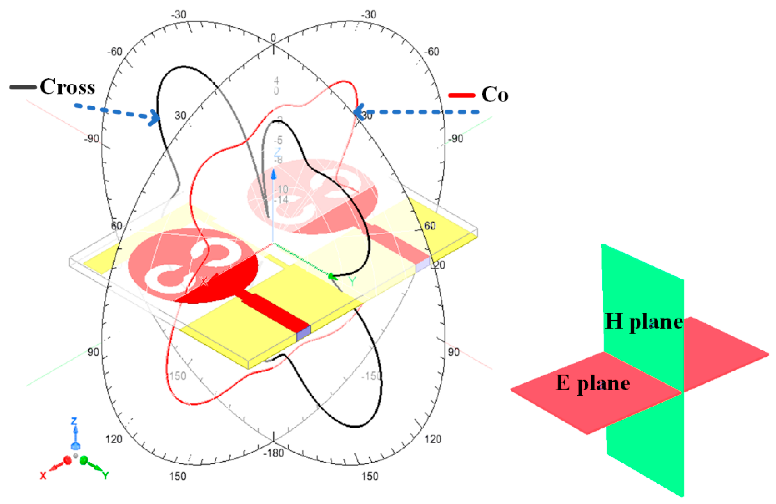
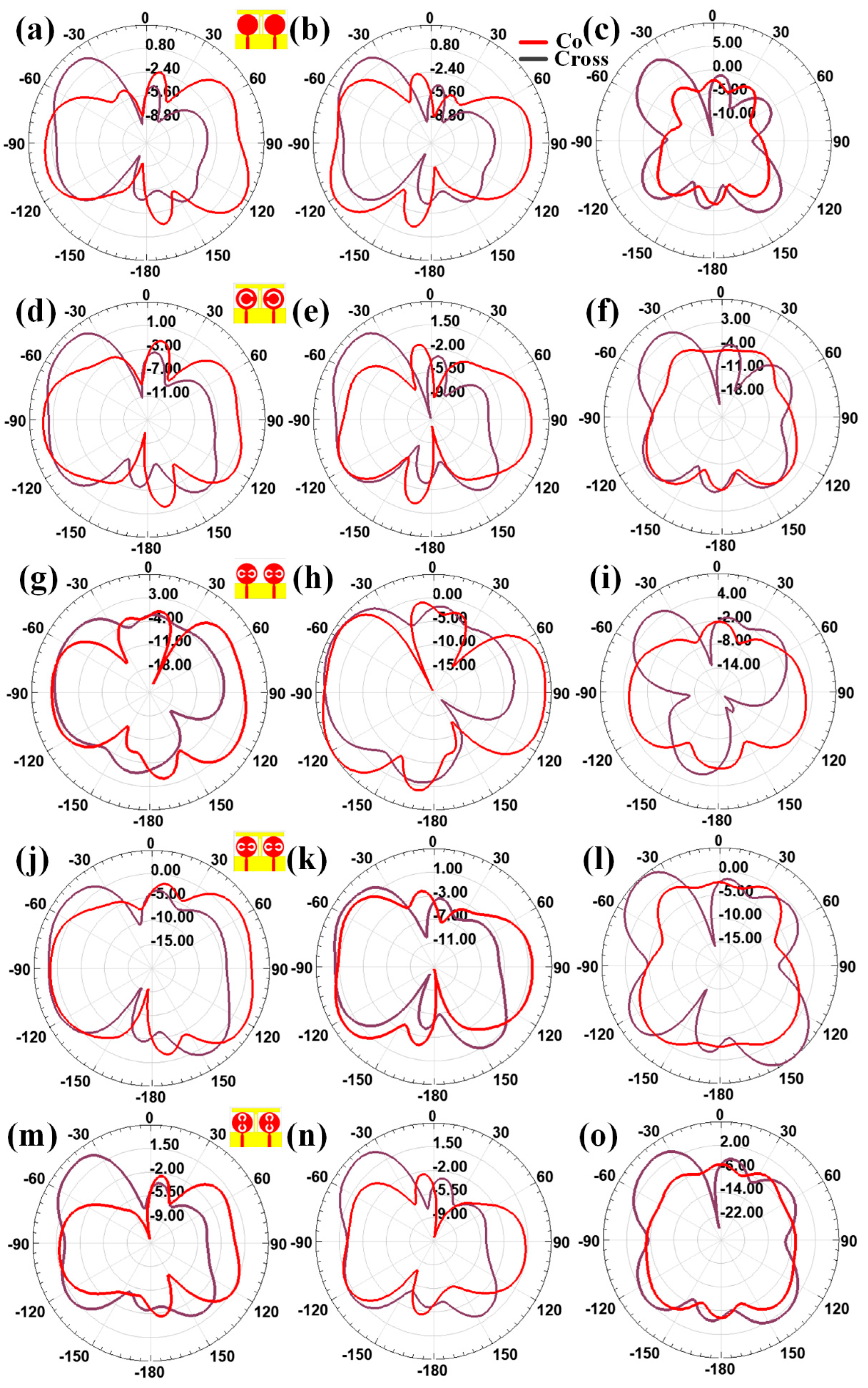
| Design | Polarization | HPBW Range (Degree) | HPBW (Degree) |
|---|---|---|---|
| 1 | Co | −180 to −173 | 7 |
| −154 to −110 | 44 | ||
| −45 to −26 | 19 | ||
| −6 to 7 | 13 | ||
| 25 to 46 | 21 | ||
| 110 to 153 | 43 | ||
| 170 to 180 | 10 | ||
| Cross | −63 to −27 | 36 | |
| 129 to 146 | 17 | ||
| 2 | Co | −148 to −106 | 42 |
| 105 to 149 | 42 | ||
| Cross | −63 to −26 | 37 | |
| 3 | Co | −134 to −59 | 75 |
| 62 to 134 | 72 | ||
| Cross | −67 to −30 | 37 | |
| 4 | Co | −180 to −175 | 5 |
| −164 to −104 | 60 | ||
| −50 to −10 | 40 | ||
| 16 t0 50 | 24 | ||
| 103 to 165 | 62 | ||
| 175 to 180 | 5 | ||
| Cross | −126 to −124 | 2 | |
| −65 to −29 | 36 | ||
| 121 to 158 | 37 | ||
| 5 | Co | −180 to −177 | 3 |
| −152 to −106 | 46 | ||
| 32 to 43 | 9 | ||
| 110 to 152 | 42 | ||
| 177 to 180 | 3 | ||
| Cross | −64 to −26 | 38 | |
| 133 to 146 | 13 |
| No of Elements | Isolation (in dB) | Design Complexity | Antenna Area (mm2) | ECC | Value of Peak Gain (dBi) | Reference |
|---|---|---|---|---|---|---|
| 2 | 25 | No | 1950 | <0.1 | >10 | This structure |
| 4 | 21 | No | 2460 | <0.25 | 6.5 | [29] |
| 2 | 20 | No | 4371 | - | 3.5 | [35] |
| 4 | 10 | No | 2025 | <0.25 | 2.75 | [19] |
| 4 | 17 | Yes | 1600 | 0.06 | 2.9 | [36] |
| 4 | 15 | No | 1600 | 0.4 | 3.5 | [37] |
| 2 | 22 | No | 640 | - | 1 | [21] |
| 4 | 10 | Yes | 5184 | <0.014 | 3.1 | [38] |
| 2 | 21 | No | 680 | - | 4 | [22] |
| 4 | 13 | No | 5624 | <0.04 | 6.2 | [39] |
| 2 | - | Yes | 2880 | <0.02 | 3 | [40] |
| 4 | 13 | Yes | 5625 | <0.04 | 6.2 | [41] |
| 4 | 15 | Yes | 16,800 | <0.10 | 5.5 | [42] |
| 2 | 15 | Yes | 13,125 | <0.15 | 5.1 | [43] |
| 4 | 11 | No | 1600 | <0.1 | 4 | [18] |
| 4 | 15.4 | Yes | 676 | <0.01 | 1.41 | [20] |
| 4 | 22 | Yes | 1750 | 0.003 | - | [44] |
Publisher’s Note: MDPI stays neutral with regard to jurisdictional claims in published maps and institutional affiliations. |
© 2022 by the authors. Licensee MDPI, Basel, Switzerland. This article is an open access article distributed under the terms and conditions of the Creative Commons Attribution (CC BY) license (https://creativecommons.org/licenses/by/4.0/).
Share and Cite
Armghan, A.; Aliqab, K.; Sorathiya, V.; Alenezi, F.; Alsharari, M.; Ali, F. Design and Fabrication of the Split Ring Resonator Shaped Two-Element MIMO Antenna with Multiple-Band Operation for WiMAX/5G/Zigbee/Wi-Fi Applications. Micromachines 2022, 13, 2161. https://doi.org/10.3390/mi13122161
Armghan A, Aliqab K, Sorathiya V, Alenezi F, Alsharari M, Ali F. Design and Fabrication of the Split Ring Resonator Shaped Two-Element MIMO Antenna with Multiple-Band Operation for WiMAX/5G/Zigbee/Wi-Fi Applications. Micromachines. 2022; 13(12):2161. https://doi.org/10.3390/mi13122161
Chicago/Turabian StyleArmghan, Ammar, Khaled Aliqab, Vishal Sorathiya, Fayadh Alenezi, Meshari Alsharari, and Farman Ali. 2022. "Design and Fabrication of the Split Ring Resonator Shaped Two-Element MIMO Antenna with Multiple-Band Operation for WiMAX/5G/Zigbee/Wi-Fi Applications" Micromachines 13, no. 12: 2161. https://doi.org/10.3390/mi13122161