
Posture Dynamic Modeling and Stability Analysis of a Magnetic Driven Dual-Spin Spherical Capsule Robot

Key Laboratory for Precision & Non-Traditional Machining of Ministry of Education of China, Dalian University of Technology, Dalian 116023, China
*
Author to whom correspondence should be addressed.
Micromachines 2021, 12(3), 238; https://doi.org/10.3390/mi12030238
Submission received: 30 January 2021
/
Revised: 18 February 2021
/
Accepted: 23 February 2021
/
Published: 26 February 2021
(This article belongs to the Special Issue Magnetic Microrobots)
Abstract
:In order to realize the intervention operation in the unstructured and ample environments such as stomach and colon, a dual-spin spherical capsule robot (DSCR) driven by pure magnetic torque generated by the universal rotating magnetic field (URMF) is proposed. The coupled magnetic torque, the viscoelastic friction torque, and the gravity torque were analyzed. Furthermore, the posture dynamic model describing the electric-magnetic-mechanical-liquid coupling dynamic behavior of the DSCR in the gastrointestinal (GI) tract was established. This model is a second-order periodic variable coefficient dynamics equation, which should be regarded as an extension of the Lagrange case for the dual-spin body system under the fixed-point motion, since the external torques were applied. Based on the Floquet–Lyapunov theory, the stability domain of the DSCR for the asymptotically stable motion and periodic motion were obtained by investigating the influence of the angular velocity of the URMF, the magnetic induction intensity, and the centroid deviation. Research results show that the DSCR can realize three kinds of motion, which are asymptotically stable motion, periodic motion, and chaotic motion, according to the distribution of the system characteristic multipliers. Moreover, the posture stability of the DSCR can be improved by increasing the angular velocity of the URMF and reducing the magnetic induction intensity.
1. Introduction
Compared with traditional endoscopy, the wireless capsule endoscopy gastrointestinal examination is safe, comfortable, and non-invasive, and has obvious advantages in the diagnosis of gastrointestinal diseases, especially for small intestine diseases [1,2]. However, the existing capsule endoscopes lack the functions of active locomotion and position control, so it was also called the passive capsule. Its diagnostic and therapeutic effects are not only limited in three-dimensional ample environments such as stomach and colon [3], but also cannot achieve future functions such as drug delivery, biopsy, and minimally invasive surgery [4]. Therefore, it has become an urgent need to extend the scope of diagnosis and treatment of capsule endoscopes to the three-dimensional ample environment and achieve the active control. Taking the built-in micro-motor as the driving source, the researchers have proposed a variety of active capsules such as bionic type [5], screw type [6], leg type [7], propeller type [8], paddle type [9], and so on. Although the micro-motor-driven capsule can achieve many convenient operations, the power capacity and space in the capsule are limited. The external non-contact driven method is more attractive from the aspects of safety and energy supply. The external non-contact driven method of the micro-robot include the acoustic field [10], the light field [11], the electric field [12], and the magnetic field [13]. Among all the methods mentioned above, the magnetic field actuation is the most promising one for in vivo applications, due to the advantages of high tissue penetration, good biocompatibility, and precise multi-degree-of-freedom control [14].
Magnetically driven capsules can usually be divided into magnetic force and magnetic torque drive modes [15]. For the magnetic force mode, the gradient magnetic field generated by the external permanent magnet or coil can apply magnetic attraction force to the capsule embedded with the permanent magnet, so as to realize the active movement of the capsule in the GI tract [16,17]. Although the magnetic force mode has the advantages of a simple working principle and low cost, the precise movement and control is not always possible, since the magnetic force can vary depending on the angle and the distance between the capsule and the external magnet driver [18]. At the same time, this drive mode also exists the problem of pose singularity in certain areas of the working space [19].
The magnetic torque driving method is mainly divided into two types. One is to use the static magnetic torque generated by the gradient magnetic field to realize the rolling locomotion of the capsule [20,21]. The other is to use the dynamic magnetic torque generated by the uniform rotating magnetic field to drive the capsule [22]. For the preceding type, the magnetic force is coupled with the magnetic torque. Therefore, the control flexibility and motion accuracy seem low. For the latter type, since the uniformly rotating magnetic field eliminates the coupling of magnetic force and magnetic torque, and the arbitrary adjustment of the direction, strength, and rotation speed of the magnetic field can be realized [23], it has higher controllability and flexibility. Although the researchers have realized the active movement of the capsule using the uniform rotating magnetic field [24], the accuracy of posture control needs to be further improved. In fact, the accurate posture control can be achieved only by realizing the separation of the capsule posture adjustment and locomotion. Fortunately, the dual-spin body provides the possibility to achieve this goal.
Meanwhile, to ensure the safe and reliable operation in the GI tract, the stability of the capsule robot needs to be studied. For the stability of the dual-spin body, researchers have launched a series of studies. Likins [25] obtained the posture stability region of the dual-spin spacecraft by using the Routh–Hurwitz criterion. Ling Dehai [26] deduced the posture stability criterion of the dual-spin satellite through the Lyapunov method. Han and Zhang [27] derived the free posture dynamics equation of the dual-spin spacecraft and obtained the conditions for posture stability. Aslanov and Yudintsev [28] studied the posture dynamics and control of a free dual-spin gyroscope spacecraft with variable structure. The posture stability of the aforementioned dual-spin bodies was studied by the sign of the real part of the characteristic root of the differential equation or by constructing of the Lyapunov function. However, the above studies all neglected the effect of external torque. In fact, the external torque has significant impact on the posture stability of the dual-spin body [29]. At the same time, the above stability research methods are only suitable for the linear systems with constant coefficients, rather than the periodic system with variable coefficients. Fortunately, the stability of periodic systems with variable coefficients can be studied by the eigenvalues of the system transition matrix based on the Floquet–Lyapunov theory.
To achieve the accurate posture control of the capsule robot, this paper proposes a dual-spin spherical capsule robot (DSCR) driven by pure magnetic torque, which can achieve the separation and conversion of the posture adjustment and rolling locomotion. Considering the actual working conditions in the GI tract, the posture dynamics equation of the DSCR under the action of external torque was established. By using Floquet–Lyapunov theory, the stability of the periodic variable coefficient dynamic system was studied. The influences of the parameters such as the magnetic induction intensity, the angular velocity of the universal rotating magnetic field (URMF), and the centroid deviation to the system stability were analyzed.
The contributions of this paper includes: (1) A dual-spin structure capsule robot driven by the URMF was proposed, which solves the problem of coupling between magnetic force and magnetic torque of the magnetic-driven capsule robot. (2) The posture dynamics equation of the DSCR under complex torque was established, which expands the research scope of double-spin body. (3) The posture stability domain of the DSCR for the asymptotically stable motion and periodic motion were obtained.
The rest of the paper is organized as follows. The structure and the working principle of the DSCR are introduced in Section 2. The posture dynamic modeling of the DSCR is presented in Section 3. In Section 4, the posture stability of the DSCR is analyzed, then, experiments are conducted for validation in Section 5. Finally, in Section 6, conclusions are drawn.
2. System Overview
2.1. The Structure of the DSCR
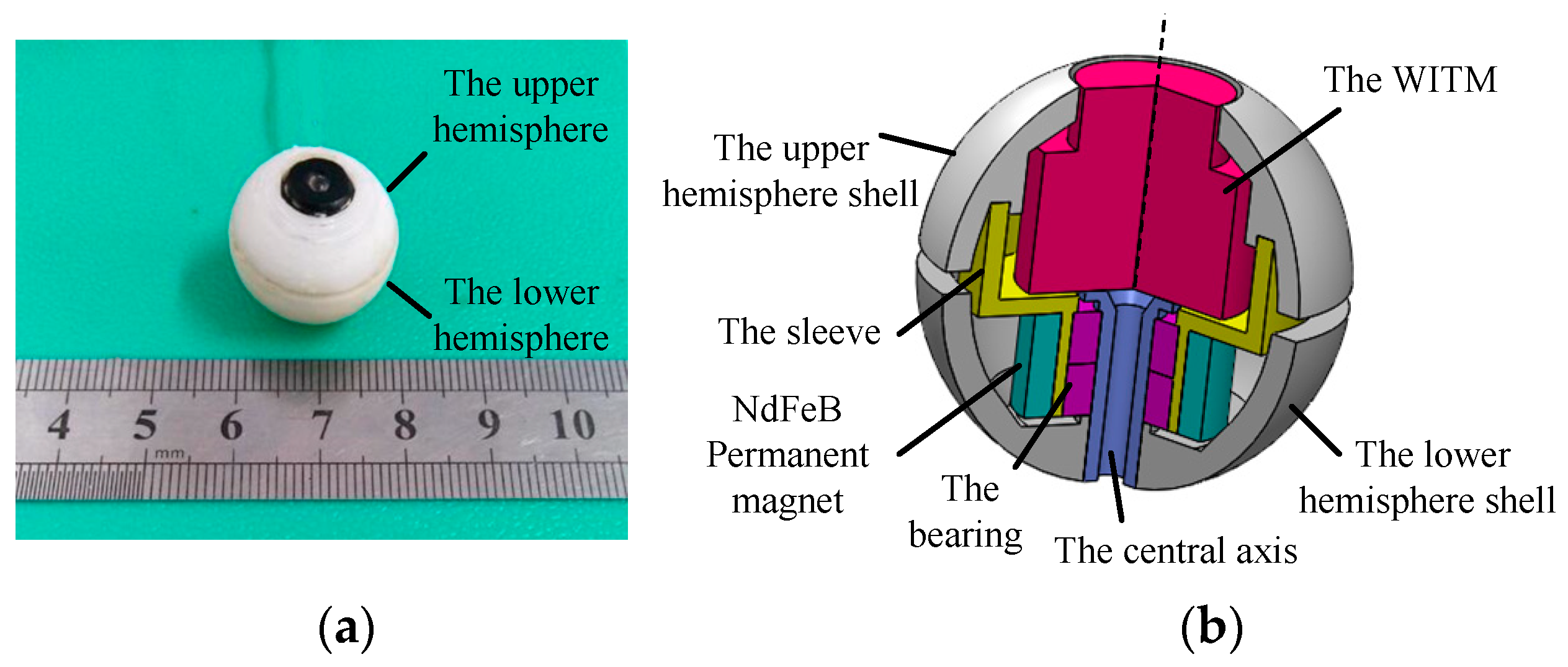
The prototype and cross-sectional view of the DSCR are shown in Figure 1a,b, respectively. The DSCR is composed of the upper and lower hemispheres, in which the upper hemispherical shell, the sleeve, and the NdFeB permanent magnet are consolidated to form the upper hemisphere. The wireless image transmission module (WITM), the central axis, and the lower hemispherical shell are consolidated to the lower hemisphere. The upper and lower hemispheres are connected by the bearing, and they can rotate relative to each other around the central axis.
The main structural parameters of the DSCR are listed in Table 1. The diameter and weight of the DSCR are 20 mm and 10 g, respectively. The brand of the radially magnetized NdFeB permanent magnet is N50 and the magnetic torque amplitude is 0.2 A.m2. The shell of the upper and lower hemispheres can be fabricated by additive manufacturing.
Because the upper hemisphere is fixated with the NdFeB permanent magnet, it can rotate about the central axis under the action of the URMF generated by the tri-axial orthogonal square Helmholtz coils (TOSHC), and the lower hemisphere is under-actuated because of the lack of driving source. Since the upper and lower hemispheres form a coaxial body and have different rotation speed around the center axis, the coaxial body further constitutes a dual-spin body [30]. The rotation of the upper hemisphere makes the DSCR have the attribute of gyroscope, while the under-actuated lower hemisphere provides a stable platform for the WITM.
2.2. Three-Phase Current Superposition Formula of the URMF
As shown in Figure 2, the three-phase alternating current feeding into the TOSHC can generate the URMF after electromagnetic induction and the superposition polarization. The three-phase current superposition formula of the URMF can be expressed as [31]
where, I0 is the amplitude of the applied electrical current. cosa, cosb, and cosc are the direction cosines of the normal vector nB of the URMF. ϕx, ϕy are the phase angles, and ϕx = arctan (cosc*cosa/cosb), ϕy = arctan (cosc*cosb/cosa).
2.3. Working Principle of the DSCR
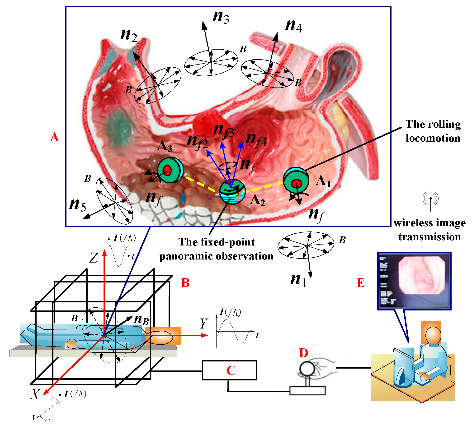
Figure 2 shows the overall medical application scenario of the DSCR inside the stomach. The whole system mainly consists of three parts: (1) the DSCR (A); (2) the TOSHC (B); and (3) the control unit of the URMF (C, D, E).
The implementation scheme is as follows: after the DSCR is swallowed and entered the A1 position of the stomach cavity, the doctor adjusts the normal vector of the URMF nB to the horizontal position n1 by manipulating the joystick (D) of the controller (C) according to the real-time image transmitted by the WITM. Under the action of the magnetic torque follow-up effect [32], the axis nf of the DSCR can follow n1 to reach the horizontal position, and then the DSCR works in the active mode, which can realize rolling locomotion on the surface of the stomach.
When the DSCR reaches the position A2, nB is adjusted from the horizontal position to the non-horizontal position, and the conversion of the DSCR from the active mode to the passive mode can be realized. When nB is adjusted to the orientations of n2, n3, and n4, the axis nf of the DSCR can be adjusted to nf2, nf3, nf4 in sequence following nB. Therefore, the fixed-point panoramic observation can be achieved with the help of the DSCR vision. If the next region needs to be observed, nB can be adjusted again to the horizontal position, as shown by n5 in Figure 2. After the DSCR rolls to the position A3, the above inspection operation process can be repeated.
In summary, the DSCR with the dual-spin structure not only can realize posture control arbitrarily, but can also realize the separation and mutual conversion of the fixed-point posture adjustment and the rolling locomotion.
3. Posture Dynamic Modeling
Since the fixed-point posture adjustment function in the passive mode is the key to the conversion of the dual mode, this paper only studies the passive mode of the DSCR.
3.1. The Description of the Posture
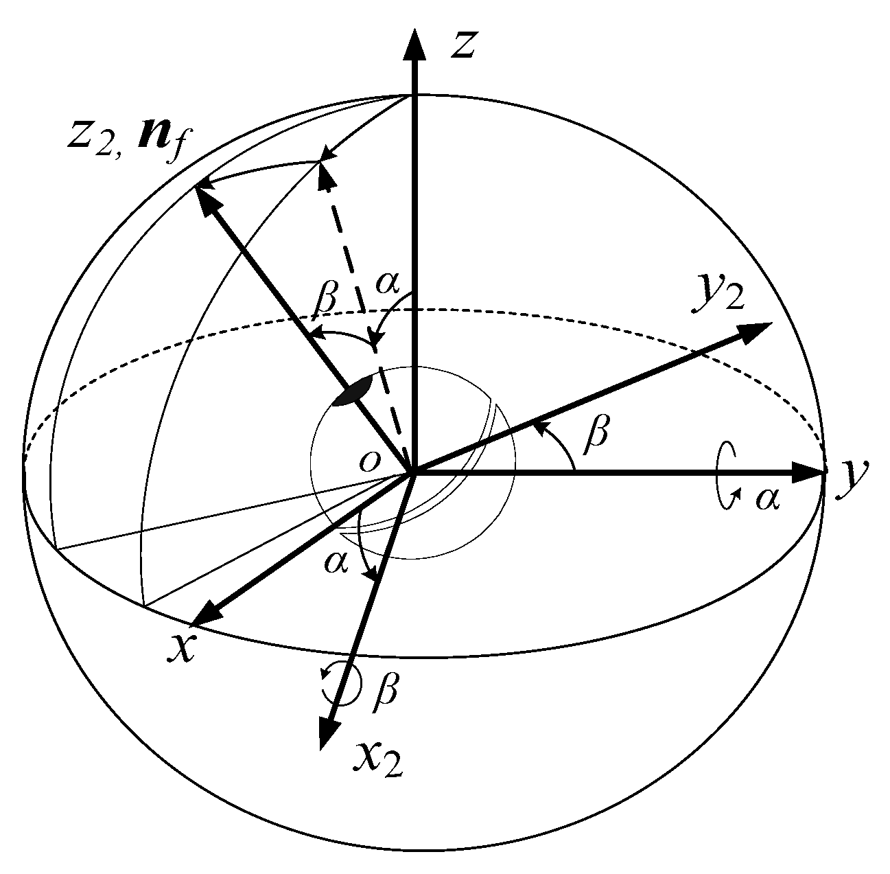
As shown in Figure 3, the posture of the DSCR can be described by the orientation of the oz2 axis of the coordinate system ox2y2z2, which is connected to the lower hemisphere of the DSCR, and the oz2 axis is coincident with the axis nf. The coordinate system ox2y2z2 can be obtained by rotating the fixed coordinate system oxyz around the oy axis by angle α (altitude angle), and then around the ox2 axis by angle β (azimuth angle). Since the rotation along the oz2 axis does not affect the orientation of the DSCR, the posture of the DSCR can be represented by the altitude angle α and the azimuth angle β, and ox2y2z2 is the résal coordinate system. Considering that the DSCR is an axisymmetric structure and the résal coordinate system ox2y2z2 is the principal axis coordinate system, then the axis nf is the polar axis.
According to Figure 3, the homogeneous transformation matrix A1 from the résal coordinate system ox2y2z2 to the fixed coordinate system oxyz can be obtained as
3.2. Torque Analysis
The external torques acting on the DSCR include: the coupling magnetic torque of the URMF and the NdFeB permanent magnet, the viscoelastic friction torque between the DSCR and the GI tract, and the gravity torque introduced by the deviation of the DSCR centroid.
3.2.1. The Coupled Magnetic Torque
To describe the basic unit of the URMF—the rotating magnetic vector B, the URMF coordinate system ox3y3z3 is introduced with the DSCR spherical center o as the coordinate origin. Where, the oz3 axis coincides with the normal vector of the URMF nB, the ox3, oy3 axis are located in the rotation plane of the rotating magnetic vector B, and form a right-handed coordinate system with oz3 axis, as shown in Figure 4.
Similar to the rotation relationship of Figure 3, ox3y3z3 can be obtained by rotating the fixed coordinate system oxyz about the oy axis by α1 firstly and then about the ox3 axis by β1, then the oz3 axis can be coincide with nB. Therefore, the orientation of the URMF can be expressed by the altitude angle α1 and the azimuth angle β1.
According to the Figure 4, the homogeneous transformation matrix A2 from the URMF coordinate system ox3y3z3 to the fixed coordinate system oxyz can be obtained as
The orientation of the URMF can be expressed in the coordinate system ox3y3z3 as
The orientation of the URMF can be expressed in the fixed coordinate system oxyz as
where, a, b, and c are the angles between the nB and each coordinate axis of the fixed coordinate system oxyz.
Since nB and nB3 are all the orientations of the URMF, the following relationship are satisfied
From the Equation (6), Equation (7) can be derived
The rotating magnetic vector B can be represented in the ox3y3z3 as
where, B is the magnetic induction intensity of the URMF, and ω is the angular velocity of the URMF.
In order to represent the rotating magnetic vector in the résal coordinate system ox2y2z2, B3 can be firstly transformed to the fixed coordinate system oxyz, then, transformed to the résal system ox2y2z2. Therefore, the rotating magnetic vector can be represented in ox2y2z2 as
where, the specific forms of E1, E2, E3, E4, E5 and E6 are following as
Since the symmetrical axis of NdFeB permanent magnet coincides with the polar axis nf, the magnetic dipole moment of the NdFeB magnet can be represented in the ox2y2z2 as
where m is the magnitude of the magnetic dipole moment. δ is the slip angle between the magnetic dipole moment and the rotating magnetic vector.
Based on the magnetic coupling theory [33], the coupling magnetic torque of the URMF and the NdFeB permanent magnet can be expressed in the résal coordinate system ox2y2z2 as
where
3.2.2. The Viscoelastic Friction Torque
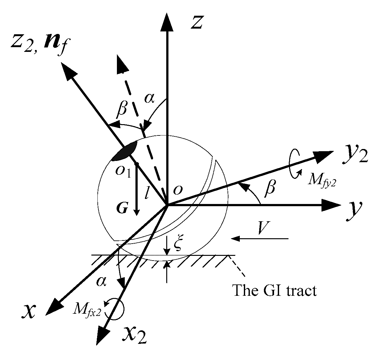
When the DSCR works in the GI tract, the deformation of the GI tract and the digestive fluid will exert a viscoelastic damping effect on the DSCR, as shown in Figure 5. It can be seen from the literature [34,35] that when the compression deformation ξ of the GI tract is small, the rolling speed V of the DSCR is much smaller than the speed of sound and the characteristic time ξ/V is much larger than the dissipation and relaxation time. Then, the torque of the viscoelastic frictional resistance to the sphere center o of the DSCR under the quasi-static state can be expressed as
where R is the radius of the DSCR. FN is the positive pressure of the DSCR on the contact surface. ωD is the angular velocity of the DSCR. k0 is the friction coefficient, which can be expressed as [30]
where η1 and η2 are the viscosity coefficient of the DSCR and the GI tract, respectively. Y and ν are the Young’s modulus and Poisson’s ratio of the GI tract. This formula relates the friction coefficient to the viscous and elastic constants of the contact material.
From the Equations (12) and (13), the projection of the viscoelastic friction torque in the résal coordinate system ox2y2z2 can be obtained as
where k is the viscous damping coefficient, . and are the angular velocity of the DSCR around the oy axis and ox2 axis, respectively.
3.2.3. The Gravity Torque
When the DSCR centroid o1 moves on the polar axis nf, its own gravity G will exert a torque on the sphere center o, as shown in Figure 5. The gravity torque can be expressed in the résal coordinate systemox2y2z2 as
where l is the modulus of the vector . When l takes a positive value, the centroid is above the sphere center. When l takes a negative value, the centroid is below the sphere center. When l = 0, the centroid coincides with the sphere center.
According to Equations (11), (14) and (15), the combined external torque acting on the DSCR can be expressed in the résal coordinate system ox2y2z2 as
3.3. Posture Dynamics Equation
Based on the theory of angular momentum change of the system in the arbitrary rotating coordinate system [36], the résal coordinate system ox2y2z2 is selected as the rotating coordinate system. The Euler dynamic equation describing the fixed-point posture adjustment of the DSCR can be expressed as
where Je is the equatorial moment of inertia of the DSCR. J1 and J2 are the polar inertia moment of the upper and lower hemisphere, respectively. {p, q, r} are the angular velocity of the lower hemisphere in ox2y2z2, and , , . σ is the angular velocity of the upper hemisphere relative to the lower hemisphere. Mx2, My2, Mz2 are the projections of the external torque in the ox2y2z2. M△ is the total external torque of the upper hemisphere along the polar axis nf (we assume M△ = 0) [36]. When the system reaches the steady state, the upper hemisphere rotates synchronously with the URMF, so it can be considered that the constant speed constraint condition is satisfied, that is, σ = ω. Considering that the resistance torque of the DSCR along the polar axis, nf can be compensated by the driving torque, that is, Mz2 = 0. Therefore, the last two formulas of Equation (17) can be ignored.
Summing up, the posture dynamic equation describing the electric-magnetic-mechanical-liquid coupling behaviour of the DSCR in the GI tract can be expressed as Equation (18). Moreover, this equation can be classified as an extension of the Lagrangian case for the coaxial bodies system—the fixed-point motion of the coaxial body under the external recovery/overturning moment.
4. Posture Stability Analysis
4.1. The Floquet–Lyapunov Theory
Since the altitude angle α and the azimuth angle β are typically small, it can be approximated as sinϑ = ϑ, cosϑ = 1, (ϑ = α, β), and the high-order small amount , , can be ignored. Introducing the dimensionless time scale τ = ωt, Equation (18) can be expressed in matrix form as
where , , ε = mB, the matrices M, N, K, F are mass matrix, damping matrix, nonlinear stiffness matrix, and external excitation matrix respectively, and
Since the matrices K(τ) and F(τ) change periodically with τ, Equation (19) is a second-order periodic variable coefficient dynamic equation. Because the stability of the non-homogeneous periodic variable coefficient dynamic equation and the corresponding homogeneous equation have the same necessary and sufficient conditions, the homogeneous form of Equation (19) in the form of first order state variables can be expressed as
where , , 0 represents zero matrix, is the second-order unit matrix, , .
Since the matrices A(τ) change periodically with τ, Equation (20) is still a periodic variable coefficient dynamic system. According to the Floquet–Lyapunov theory, the stability of the periodic variable coefficient system can be studied according to the eigenvalue λ of its transition matrix P [37]: If the modulus of all eigenvalues of P are less than 1, the system is asymptotically stable. If P has an eigenvalue whose modulus is greater than 1, the system is unstable. If the modulus of the eigenvalues of P are less than or equal to 1, and at least one of them is equal to 1, the system is limit stable. The eigenvalues of the transition matrix are also called the characteristic multipliers [38]. Therefore, the stability of the dynamic system (20) can be determined by the distribution of the characteristic multipliers of the transition matrix P.
According to the method of C.S.Hu [39], the transition matrix P of the periodic system can be calculated as
where I is the unit matrix, Nk is the number of parts that divide the period T of the periodic system equally, and each average point is represented by k = 0, 1, 2, … Nk. The kth interval can be denoted by τk and its size by . Within the interval τk, the periodic coefficient matrix Ci can be replaced by a constant coefficient matrix Ck. And A is the periodic coefficient matrix of the periodic system.
4.2. Three Stable Forms of the DSCR
The modulus of the system characteristic multiplier varies with the control parameters of the DSCR, and corresponds to three typical motion states of asymptotically stable motion, periodic motion, and chaotic motion.
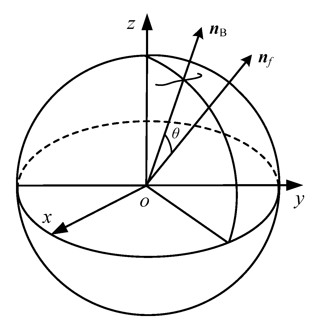
Since the polar axis nf should follow nB to change its orientation, then nB can be thought as the target orientation. When the DSCR is in different motion state, the polar axis nf and the target orientation nB have different orientation relations, the angle θ between nf and nB is defined as the orientation error of the system, as shown in Figure 6, and
where nf and nB represents the orientation of the polar axis nf and the URMF in the fixed coordinate system oxyz respectively, and
where α and β are the altitude angle and the azimuth angle of the polar axis nf. α1 and β1 are the altitude angle and the azimuth angle of the target orientation nB.
4.2.1. Asymptotically Stable Motion
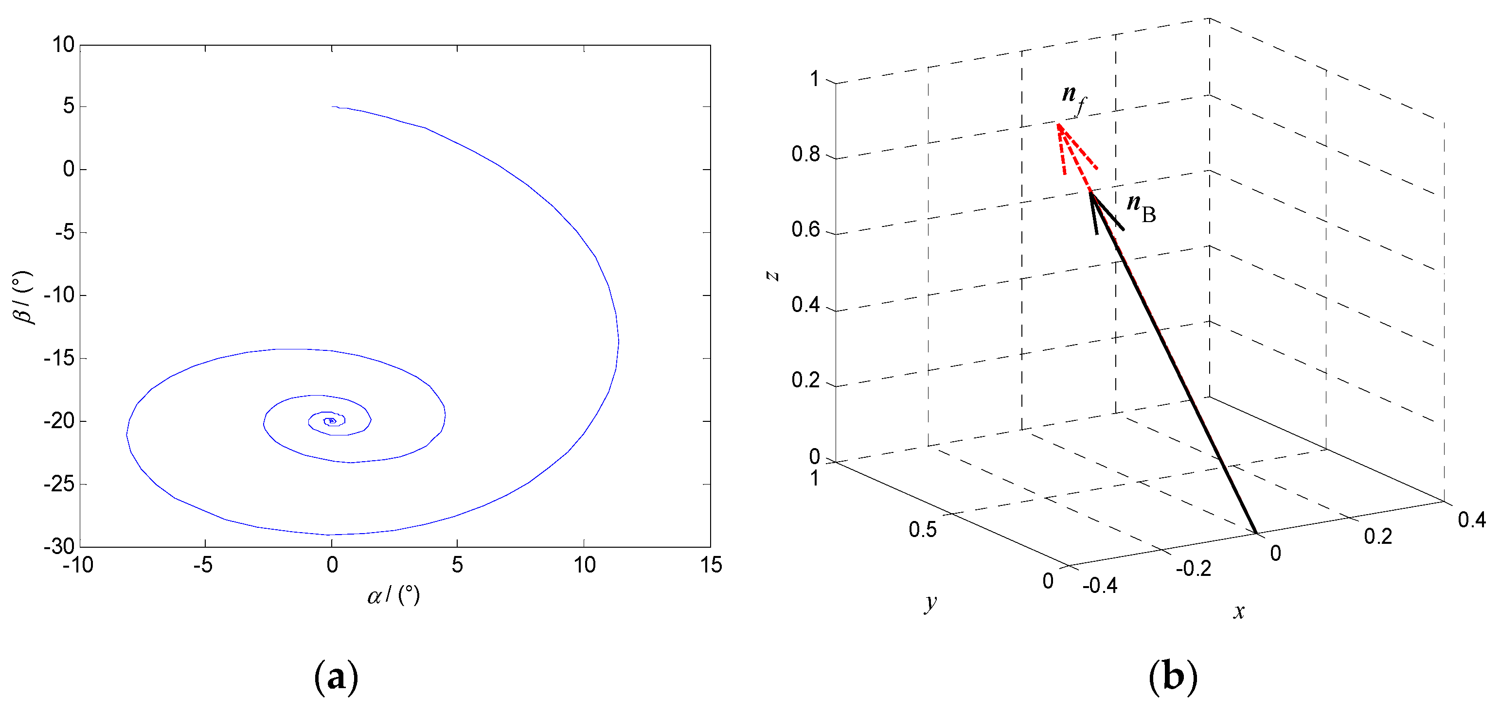
When the modulus of the characteristic multiplier is less than 1, the system phase diagram with the altitude angle α and the azimuth angle β as state variables is an asymptotically stable curve, as shown in Figure 7a. When the system reaches the steady state, the polar axis nf and the target orientation nB coincide in the fixed coordinate system oxyz, as shown in Figure 7b.
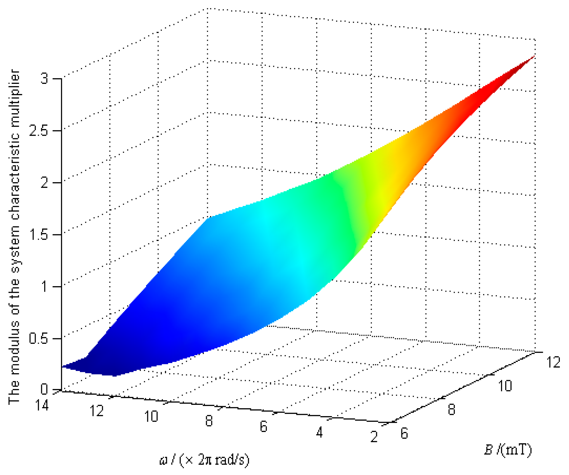
When the angular velocity of the URMF ω and the magnetic induction intensity B vary widely, the variation law of the modulus of the system characteristic multipliers was obtained, as shown in Figure 8.
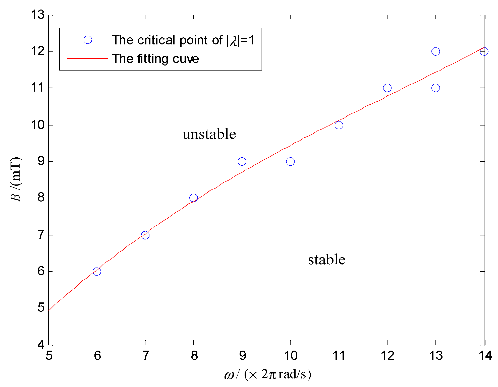
Figure 8 shows that the modulus of the system characteristic multiplier decreases with ω and increases with B. The critical points of Figure 8, which satisfy the modulus of the system characteristic multipliers λ equal 1 was extracted, and the data was fitted by the least square method. Then, the stability domain of the system in the parameter space of ω and B can be obtained, as shown in Figure 9.
In Figure 9, the stability domain is divided into two parts by the critical point of . In the upper region, , and the system is unstable. On the contrary, the DSCR can keep the posture stable in the lower region of . Figure 9 shows that the posture stability of the DSCR can be improved by increasing the angular velocity of the URMF and decreasing the magnetic induction intensity. The reason is that when the rotational speed of the upper hemisphere increases with the URMF, the stability of the system can be improved under the gyroscopic effect. While the torque balance of the system may be destroyed by increasing the magnetic induction intensity.
4.2.2. Stability of the Periodic Motion
When the modulus of the system characteristic multiplier is equal 1, the steady state phase diagram of the system with the altitude angle α and the azimuth angle β as state variables is a curve of periodic oscillation, as shown in Figure 10a, and the polar axis nf precesses near nB, as shown in Figure 10b.
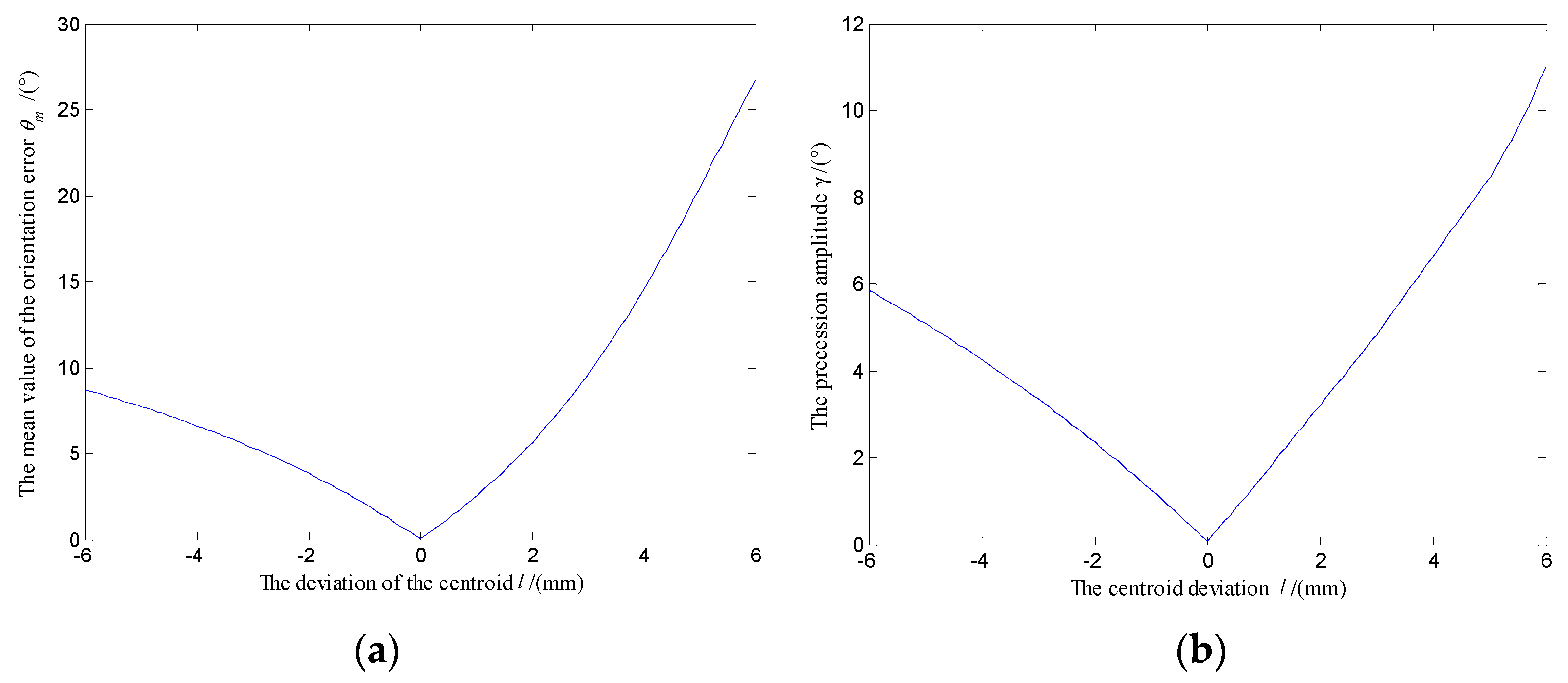
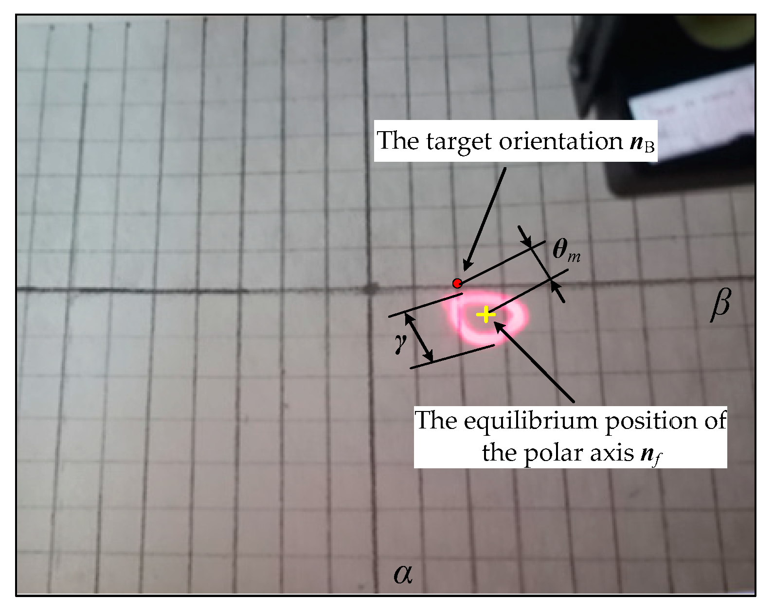
In order to explore the precession law of the polar axis nf, the angle θm between the equilibrium position of the polar axis nf and the target orientation nB is defined as the mean orientation error of the system, and the swing angle γ of the polar axis nf is defined as the precession amplitude of the system, as shown in Figure 10b. Fix ω = 18π rad/s, B = 7 mT, the variation law of θm and γ with the centroid deviation l were obtained, as shown in Figure 11a,b, respectively.
Figure 11 shows that when the centroid approaches the sphere center along the polar axis nf from below (l < 0), the mean orientation error and the precession amplitude of the system are both decreasing. When the centroid coincides with the sphere center (l = 0), the mean orientation error and the precession amplitude of the system are zeros. When the centroid deviates the sphere center along the polar axis nf from upwards (l > 0), the mean orientation error and the precession amplitude of the system both keep increasing. At the same time, compared with the upward deviation of the centroid along the polar axis nf, when the centroid is deviated downward, the mean orientation error and the precession amplitude of the system are smaller. Therefore, in the assembly and manufacturing process, the centroid of the DSCR should be coincident with the sphere center as far as possible.
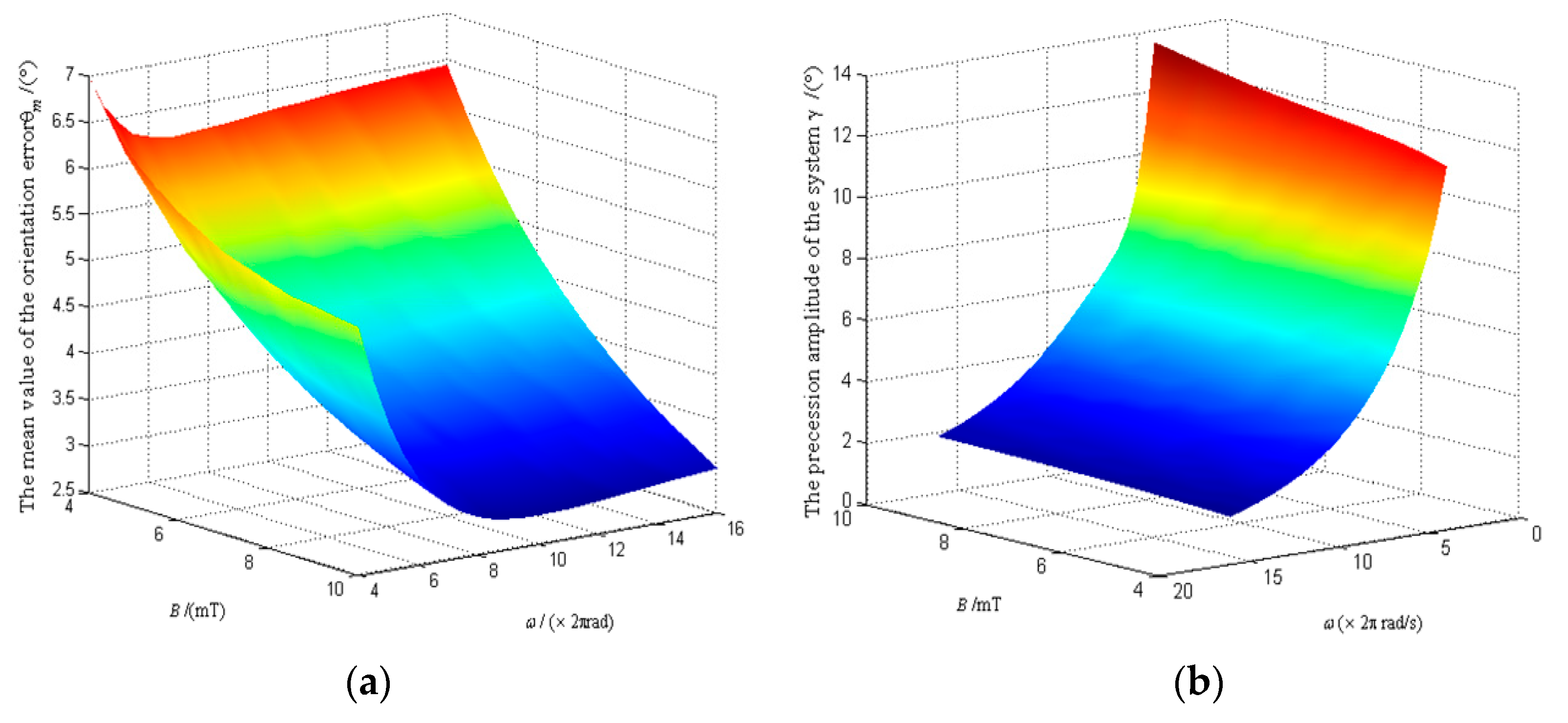
When the angular velocity of the UMMF ω and the magnetic induction intensity B vary over a wide range, the variation law of mean orientation error θm and the precession amplitude γ with ω and B as the control variables are showed in Figure 12a,b, respectively.
Figure 12a shows that the mean orientation error of the system can be reduced by increasing ω and B simultaneously. While Figure 12b shows that increasing ω and decreasing B can significantly reduce the precession amplitude of the system.
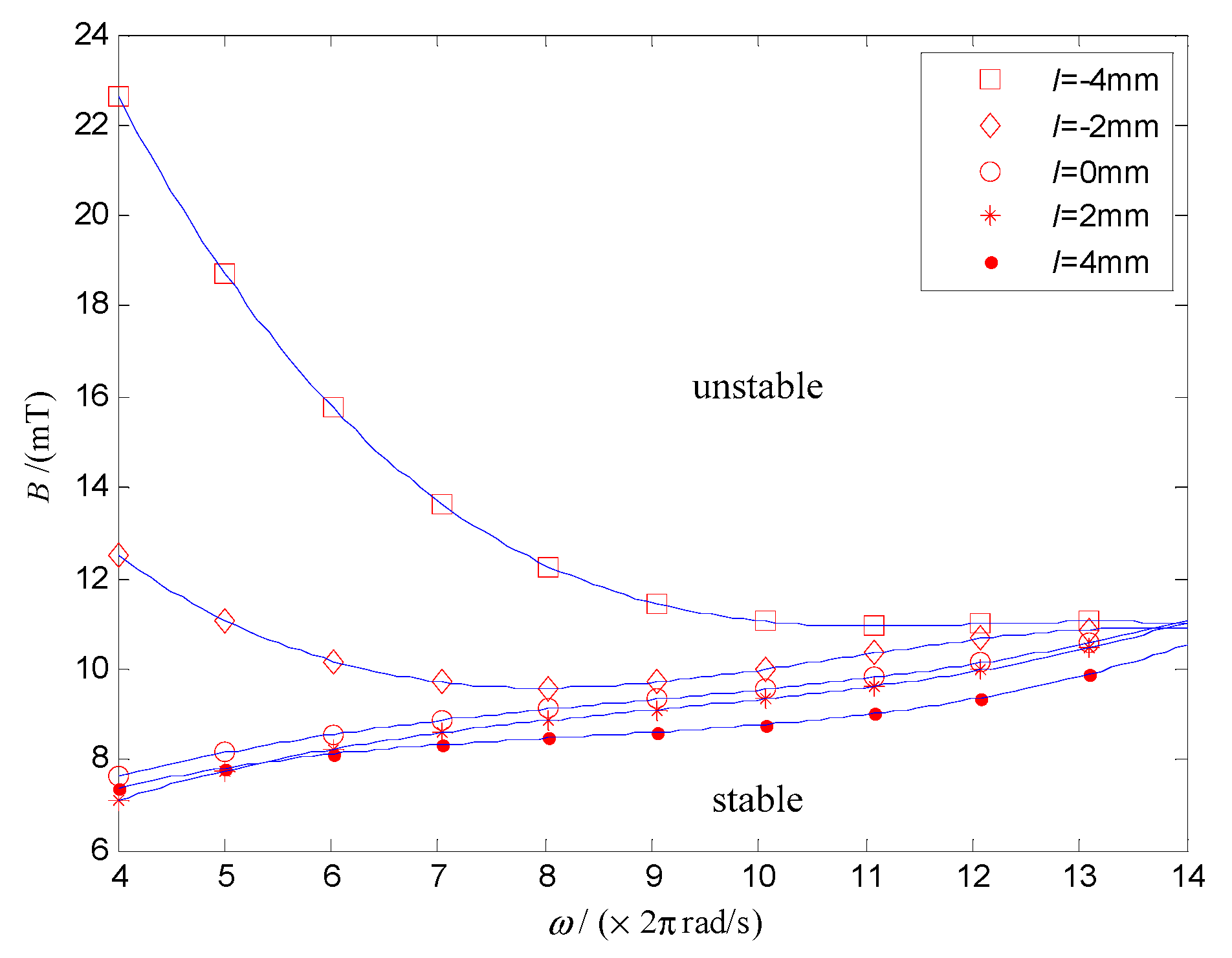
To explore the stability of the DSCR for the periodic motion, taking ω and B as the control parameters, the stability domain of the system under different centroid deviation is shown in Figure 13. The upper and lower areas of the curve represent the stable domain and unstable domain, respectively. Similar to Figure 9, Figure 13 shows that increasing the angular velocity of the URMF and decreasing the magnetic induction intensity can improve the stability of periodic motion of the system.
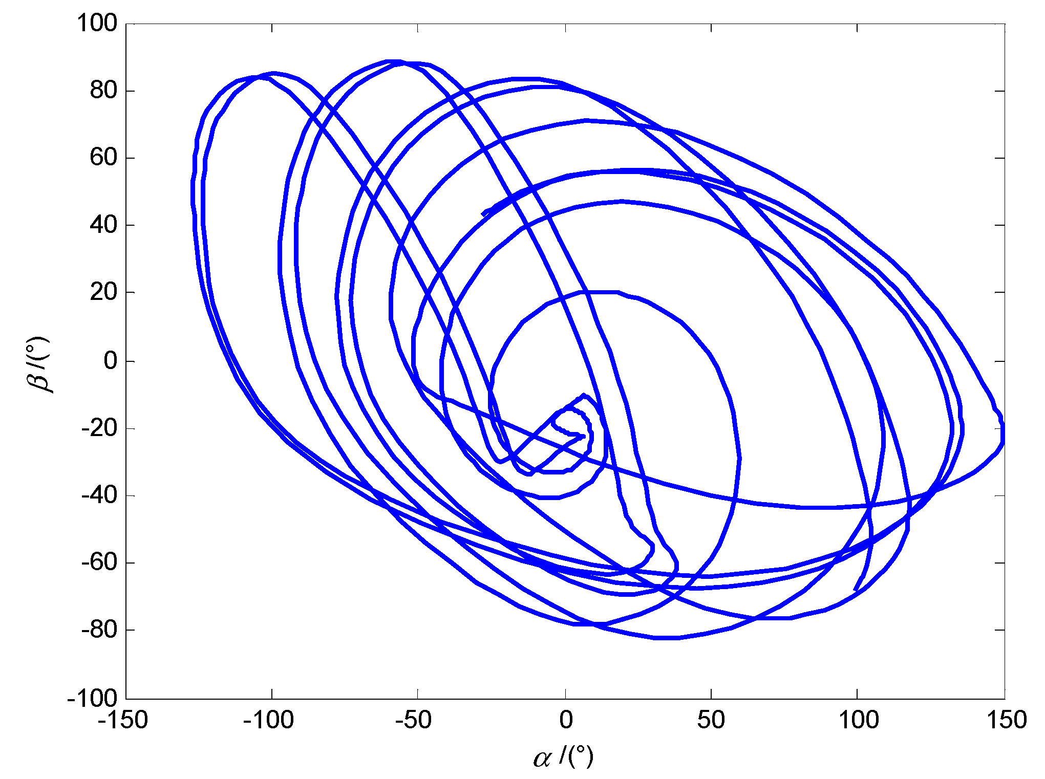
4.2.3. Chaotic Motion
As shown in Figure 14, when the modulus of the system characteristic multiplier is greater than 1, the system phase diagram with the altitude angle α and the azimuth angle β as state variables is chaotic, and the posture of the DSCR is unstable, which corresponding to the control condition of ω = 18π rad/s, B = 12 mT, l = 0 mm.
5. Experiment and Discussion
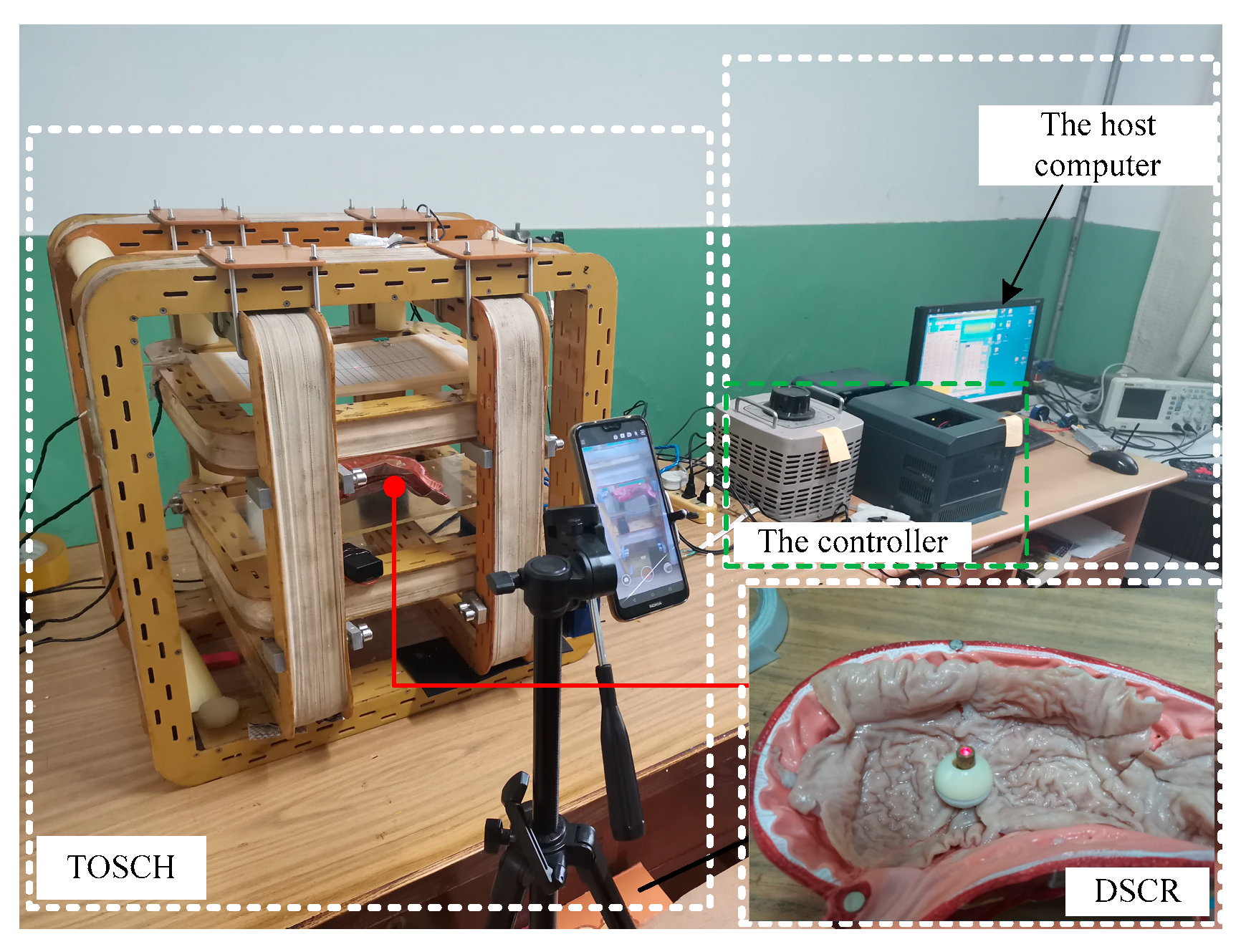
To verify the theoretical analysis results, an experiment platform as shown in Figure 15 was built. The platform consists of the host computer, the controller, the TOSHC, and the DSCR. When the angular velocity of the UMMF ω, the magnetic induction intensity B, and the orientation of the URMF nB are input to the host computer, the controller can generate three-phase electric power that meet the control requirements, and the URMF can be generated after the three-phase alternating current are fed into the TOSHC. Since the orientation of the URMF can be controlled by the direction cosine of nB, and the axis nf of the DSCR can follow nB to change its orientation, then the posture of the DSCR can be controlled by nB. In order to simulate the environment of the GI tract, the isolated porcine intestinal tissue was spread on the surface of the stomach model.
5.1. Principle of the Polar Axis Orientation Measurement
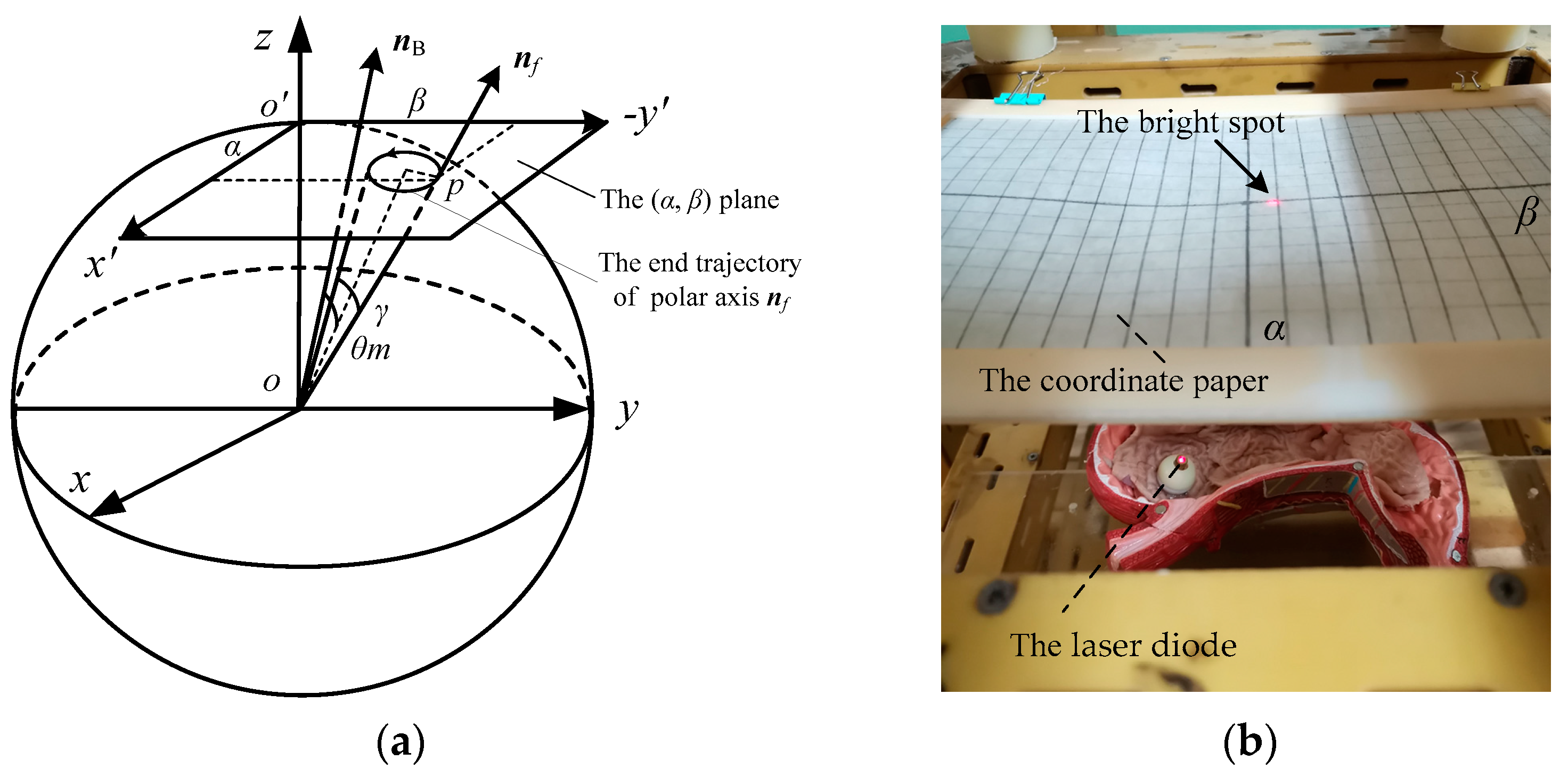
The schematic diagram and physical diagram of the orientation measuring device of the polar axis nf are shown in Figure 16a,b, respectively. As shown in Figure 16a, the unit sphere with the DSCR spherical center o as the coordinate origin, and the unit sphere is intersected with the oz axis of the fixed coordinate system oxyz at the point o’. The tangent plane (x′, y′) of the unit sphere is parallel to the plane (x, y). According to Figure 3, the coordinates of the point p, which is the intersection point of the polar axis nf and the (x′, y′) plane can be obtained as
When the polar axis nf moves in a small range near the oz axis, the second order small quantities of α, β are omitted, and the above equation can be simplified as
The x′ axis is called α axis, and the −y′ axis is called β axis, so the trajectory of the polar axis nf on the unit sphere can be approximately replaced by the trajectory on the (α, β) plane, that is, the plane pole trajectory. Moreover, the mean orientation error and the precession amplitude of the system are represent by the angles θm and γ, respectively.
As shown in Figure 16b, the wireless image transmission module of the DSCR was replaced with a laser diode. The coordinate paper is placed at h = 100 mm above the sphere center of the DSCR. The bright spot of the laser diode on the coordinate paper can reflect the end motion trajectory of the polar axis nf in real time, and the trajectory can be recorded by the camera. The horizontal and vertical axes of the coordinate paper correspond to the altitude angle α and the azimuth angle β, respectively. Moreover, each scale on the coordinate paper represents 10°.
5.2. The Posture Stability Experiment
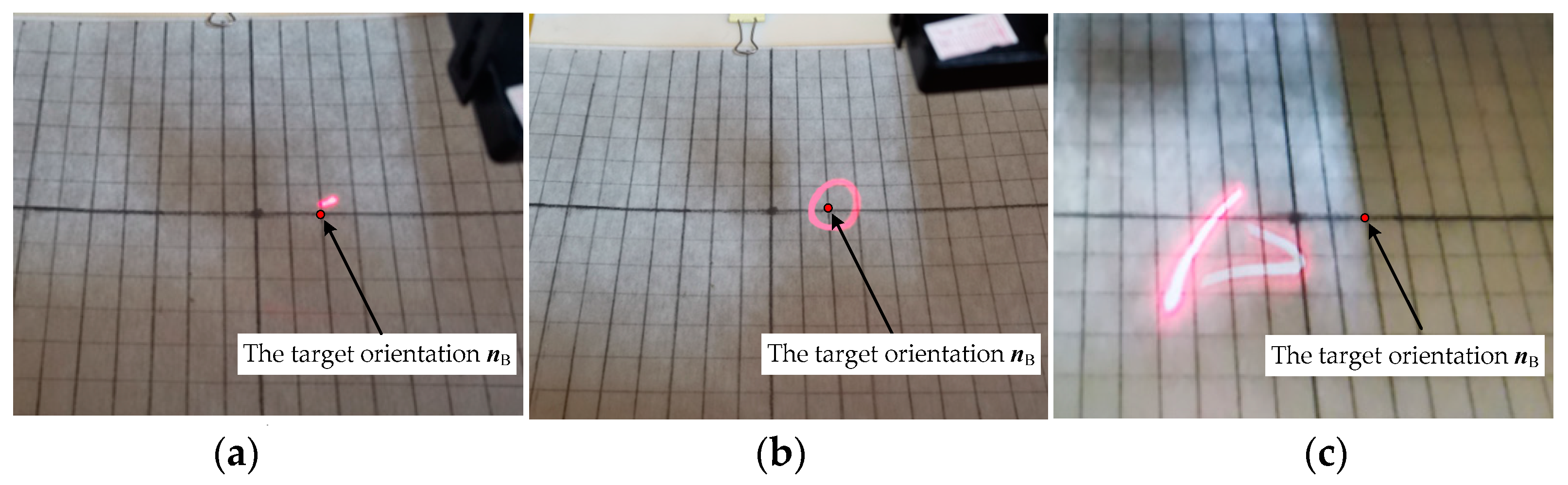
To verify the posture stability of the DSCR, three groups of cross experiments were designed as shown in Table 3, and the DSCR with no centroid deviation was used. Set the target orientation nB = (0°, −20°), when ω and B are controlled to change in turn, the end motion trajectories of the polar axis nf are shown in Figure 17a–c, respectively.
Figure 17a shows that the end motion trajectory of the polar axis nf is a fixed point when ω = 18π rad/s, B = 7 mT, which indicates that the system is asymptotically stable and the polar axis nf coincides with the target orientation nB. While Figure 17b shows that the end motion trajectory of the polar axis nf is a curve of the periodic motion when ω = 14π rad/s, B = 7 mT, which indicates that the polar axis nf makes the precession motion around the target orientation nB. Moreover, the end motion trajectory of the polar axis nf in Figure 17c is an irregular curve, indicating the chaotic motion of the system for the control parameters of ω = 18π rad/s, B = 12 mT. The above three groups of experiment results are consistent with the results in Figure 9.
5.3. The Precession Experiment
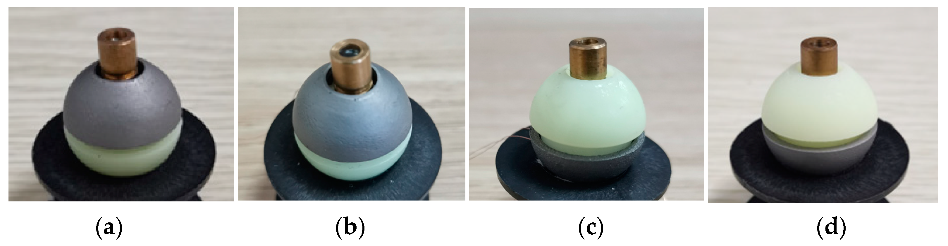
To verify the precession characteristics of the polar axis nf when the DSCR makes the period motion, four DSCR models as shown in Figure 18 were 3D printed and assembled. The four DSCR models have the same weight and size except the centroid deviation, and the centroid deviation along the polar axis nf is 4 mm, 2 mm, −2 mm, −4 mm, respectively.
Set ω = 18π rad/s, B = 7 mT, and the target orientation nB = (0°, −20°), the end motion trajectories of the polar axis nf of the centroid deviation l = −4 mm is shown in Figure 19. From the equilibrium position and the end motion trajectory of the polar axis nf, the mean orientation error θm and the precession amplitude γ as shown in Figure 16a can be obtained. Table 4 shows the precession results of the polar axis nf for the four DSCR models of Figure 18.
Table 4 shows that when the centroid approaches the sphere center from above or below, the mean orientation error and the precession amplitude of the system both gradually decreases. When the centroid is deviated up or down the same distance along the polar axis nf, the mean orientation error and the precession amplitude are smaller when the centroid moves down. The experiment results are consistent with the simulation results of Figure 11. The error of theoretical calculation and experimental data may be caused by the manufacturing and assembly errors of the DSCR and the system error of the orientation measuring device of the polar axis nf.
6. Conclusions
The DSCR with a dual-spin structure driven by the URMF was proposed, which can realize the fixed-point posture adjustment in the passive mode and the rolling locomotion in the active mode. The posture dynamics equation of the DSCR and the stability domain for the asymptotically stable motion and the periodic motion based on the Floquet–Lyapunov theory were obtained.
In general, we conclude that the DSCR makes the asymptotically stable motion, the periodic motion, the chaotic motion respectively, when the system characteristic multipliers less than 1, equal to 1, and greater than 1 are satisfied. In detail, increasing the angular velocity of the URMF and reducing the magnetic induction intensity can improve the posture stability of the DSCR. Decreasing the centroid deviation, increasing the angular velocity of the URMF can reduce the mean orientation error and the precession amplitude of the system. At the same time, compared with the upward deviation of the centroid along the polar axis, when the centroid is deviated downward, the orientation error and the precession amplitude of the system are smaller.
This research has laid a solid foundation for the structural improvement and the posture control of the DSCR.
Author Contributions
Conceptualization, Y.Z. and H.Y.; methodology, H.Y.; software, H.Y.; validation, Z.L., X.L. and G.L.; writing—original draft preparation, H.Y.; writing—review and editing, Y.Z. and H.Y. All authors have read and agreed to the published version of the manuscript.
Funding
This work was funded by National Natural Science Foundation of China, grant numbers 61773084.
Acknowledgments
We also acknowledge Professor Ming Yue from the School of Automotive Engineering, Dalian University of Technology for his guidance in the writing of this paper.
Conflicts of Interest
The authors declare no conflict of interest.
References
- Popek, K.M.; Schmid, T.; Abbott, J.J. Six-degree-of-freedom localization of an untethered magnetic capsule using a single rotating magnetic dipole. IEEE Robot. Autom. Lett. 2017, 2, 305–312. [Google Scholar] [CrossRef]
- Iddan, G.; Meron, G.; Glukhovsky, A.; Swain, P. Wireless capsule endoscopy. Nature 2000, 405, 417. [Google Scholar] [CrossRef] [PubMed]
- Goenka, M.K.; Majumder, S.; Goenka, U. Capsule endoscopy: Present status and future expectation. World J. Gastroenterol. 2014, 10024–10037. [Google Scholar] [CrossRef] [PubMed]
- Ye, B.; Zhang, W.; Sun, Z.-J.; Guo, L.; Deng, C.; Chen, Y.-Q.; Zhang, H.-H.; Liu, S. Study on a magnetic spiral-type wireless capsule endoscope controlled by rotational external permanent magnet. J. Magn. Magn. Mater. 2015, 395, 316–323. [Google Scholar] [CrossRef]
- Han, D.; Yan, G.; Wang, Z.; Jiang, P.; Liu, D.; Zhao, K.; Ma, J. The modelling, analysis, and experimental validation of a novel micro-robot for diagnosis of intestinal diseases. Micromachines 2020, 11, 896. [Google Scholar] [CrossRef] [PubMed]
- Dachlika, T.; Zarrouk, D. Mechanics of locomotion of a double screw crawling robot. Mech. Mach. Theory 2020, 153, 104010. [Google Scholar] [CrossRef]
- Sun, Z.-J.; Ye, B.; Qiu, Y.; Cheng, X.-G.; Zhang, H.-H.; Liu, S. Preliminary study of a legged capsule robot actuated wirelessly by magnetic torque. IEEE Trans. Magn. 2014, 50, 1–6. [Google Scholar] [CrossRef]
- Tortora, G.; Valdastri, P.; Susilo, E.; Menciassi, A.; Dario, P.; Rieber, F.; Schurr, M.O. Propeller-based wireless device for active capsular endoscopy in the gastric district. Minim. Invasive Ther. Allied Technol. 2009, 18, 280–290. [Google Scholar] [CrossRef] [PubMed]
- Kim, H.M.; Yang, S.; Kim, J.; Park, S.; Cho, J.H.; Park, J.Y.; Kim, T.S.; Yoon, E.-S.; Song, S.Y.; Bang, S. Active locomotion of a paddling-based capsule endoscope in an in vitro and in vivo experiment (with videos). Gastrointest. Endosc. 2010, 72, 381–387. [Google Scholar] [CrossRef]
- Xu, T.; Xu, L.P.; Zhang, X.; Wang, S.; Gao, W. Micro-/nanomachines: Fuel-free synthetic micro-/nanomachines (Adv. Mater. 9/2017). Adv. Mater. 2017, 29, 29. [Google Scholar] [CrossRef] [Green Version]
- Safdar, M.; Simmchen, J.; Jänis, J. Correction: Light-driven micro- and nanomotors for environmental remediation. Environ. Sci. Nano 2017, 4, 2235. [Google Scholar] [CrossRef] [Green Version]
- Han, K.; Shields, C.W.; Velev, O.D. Engineering of self-propelling microbots and microdevices powered by magnetic and electric fields. Adv. Funct. Mater. 2018, 28, 28. [Google Scholar] [CrossRef]
- Peyer, K.E.; Tottori, S.; Qiu, F.; Zhang, L.; Nelson, B.J. Magnetic helical micromachines. Chem. A Eur. J. 2012, 19, 28–38. [Google Scholar] [CrossRef] [PubMed]
- Wang, B.; Kostarelos, K.; Nelson, B.J.; Zhang, L. Trends in micro-/nanorobotics: Materials development, actuation, localization, and system integration for biomedical applications. Adv. Mater. 2021, 33, 1–44. [Google Scholar] [CrossRef] [PubMed]
- Swain, P.; Toor, A.; Volke, F.; Keller, J.; Gerber, J.; Rabinovitz, E.; Rothstein, R.I. Remote magnetic manipulation of a wireless capsule endoscope in the esophagus and stomach of humans (with videos). Gastrointest. Endosc. 2010, 71, 1290–1293. [Google Scholar] [CrossRef]
- Rahman, I.; Pioche, M.; Shim, C.; Sung, I.; Saurin, J.-C.; Patel, P. PTU-028 first human series of magnet assisted capsule endoscopy (mace) in the upper gi tract using The Novel Mirocam-navi System. Gut 2014, 63, A50. [Google Scholar] [CrossRef] [Green Version]
- Rahman, I.; Pioche, M.; Shim, C.S.; Lee, S.P.; Sung, I.-K.; Saurin, J.-C.; Patel, P. Magnetic-assisted capsule endoscopy in the upper GI tract by using a novel navigation system (with video). Gastrointest. Endosc. 2016, 83, 889–895.e1. [Google Scholar] [CrossRef]
- Rahman, I.; Afzal, N.A.; Patel, P. The role of magnetic assisted capsule endoscopy (MACE) to aid visualisation in the upper GI tract. Comput. Biol. Med. 2015, 65, 359–363. [Google Scholar] [CrossRef]
- Taddese, A.Z.; Slawinski, P.R.; Pirotta, M.; De Momi, E.; Obstein, K.L.; Valdastri, P. Enhanced real-time pose estimation for closed-loop robotic manipulation of magnetically actuated capsule endoscopes. Int. J. Robot. Res. 2018, 37, 890–911. [Google Scholar] [CrossRef] [PubMed]
- Carpi, F.; Kastelein, N.; Talcott, M.; Pappone, C. Magnetically controllable gastrointestinal steering of video capsules. IEEE Trans. Biomed. Eng. 2011, 58, 231–234. [Google Scholar] [CrossRef]
- Yim, S.; Gultepe, E.; Gracias, D.H.; Sitti, M. Biopsy using a magnetic capsule endoscope carrying, releasing, and retrieving untethered microgrippers. IEEE Trans. Biomed. Eng. 2014, 61, 513–521. [Google Scholar] [CrossRef] [PubMed] [Green Version]
- Fu, Q.; Guo, S.; Yamauchi, Y.; Hirata, H.; Ishihara, H. A novel hybrid microrobot using rotational magnetic field for medical applications. Biomed. Microdevices 2015, 17, 1–12. [Google Scholar] [CrossRef] [PubMed]
- Zhang, Y.; Su, Z.; Chi, M.; Huang, Y.; Wang, D. Magnitude and orientation error correction of a superimposed spatial universal rotating magnetic vector. IEEE Trans. Magn. 2016, 52, 1–9. [Google Scholar] [CrossRef]
- Choi, H.; Jeong, S.; Lee, C.; Park, B.J.; Ko, S.Y.; Park, J.-O.; Park, S. Three-dimensional swimming tadpole mini-robot using three-axis Helmholtz coils. Int. J. Control. Autom. Syst. 2014, 12, 662–669. [Google Scholar] [CrossRef]
- Likins, P.W. Attitude stability criteria for dual spin spacecraft. J. Spacecr. Rocket. 1967, 4, 1638–1643. [Google Scholar] [CrossRef]
- Dehai, L. Attitude stability criterion of dual-spin satellites. Attitude Stab. Criterion Dual Spin Satell. 1982, 02, 55–63. [Google Scholar]
- Guang-Cai, H.; Yao-Liang, Z. Dynamic attitude equations and stability study of dual spinning satellites. J. Harbin Eng. Univ. 2004. [Google Scholar]
- Aslanov, V.S.; Yudintsev, V. V Dynamics and control of dual-spin gyrostat spacecraft with changing structure. Celest. Mech. Dyn. Astron. 2013, 115, 91–105. [Google Scholar] [CrossRef]
- Zhang, M.-J.; Zhao, C.-Y. Attitude stability of a dual-spin spacecraft on a stationary orbit around an asteroid subjected to gravity gradient torque. Astrophys. Space Sci. 2015, 355, 203–212. [Google Scholar] [CrossRef]
- Kaplan, M.H. Modern Spacecraft Dynamics and Control; John Wiley & Sons: Hoboken, NJ, USA, 1976. [Google Scholar]
- Control theorem of a universal uniform-rotating magnetic vector for capsule robot in curved environment. Sci. China Technol. Sci. 2013, 359–368.
- Zhang, Y.S.; Su, Z.K.; Yang, Z.Q. A Control Strategy for Posture Adjustment and Steering-Driven of the Dual Hemisphere Capsule robot. China Patent CN104983385-A, 21 October 2015. [Google Scholar]
- Kim, S.H.; Ishiyama, K. Magnetic robot and manipulation for active-locomotion with targeted drug release. IEEE/ASME Trans. Mechatronics 2014, 19, 1651–1659. [Google Scholar] [CrossRef]
- Brilliantov, N.; Pöschel, T. Rolling friction of a viscous sphere on a hard plane. Europhys. Lett. 1998, 42, 511–516. [Google Scholar] [CrossRef] [Green Version]
- Flom, D.G.; Bueche, A.M. Theory of rolling friction for spheres. J. Appl. Phys. 1959, 30, 1725–1730. [Google Scholar] [CrossRef]
- Doroshin, A.V. Exact solutions for angular motion of coaxial bodies and attitude dynamics of gyrostat-satellites. Int. J. Non-linear Mech. 2013, 50, 68–74. [Google Scholar] [CrossRef]
- Weyh, B.; Kostyra, H. Direct floquet method for stability limits determination—I. Mech. Mach. Theory 1991, 26, 123–131. [Google Scholar] [CrossRef]
- Brown, B.M.; Eastham, M.S.; Schmidt, K.M. Periodic Differential Operators; Springer: Basel, Switzerland, 2013; Volume 10. [Google Scholar]
- Friedmann, P.; Hammond, C.E.; Woo, T.-H. Efficient numerical treatment of periodic systems with application to stability problems. Int. J. Numer. Methods Eng. 1977, 11, 1117–1136. [Google Scholar] [CrossRef]
- Friedmann, P.P. Numerical methods for the treatment of periodic systems with applications to structural dynamics and helicopter rotor dynamics. Comput. Struct. 1990, 35, 329–347. [Google Scholar] [CrossRef]
Figure 1.
The structure of the dual-spin spherical capsule robot (DSCR). (a) The prototype, (b) the 3D cross-sectional view.
Figure 1.
The structure of the dual-spin spherical capsule robot (DSCR). (a) The prototype, (b) the 3D cross-sectional view.

Figure 2.
Application scenario of the DSCR and the control system of the universal rotating magnetic field (URMF). A: Double working mode of the DSCR: The fixed-point panoramic observation in the passive mode (n2, n3, n4); The rolling locomotion in the active mode (n1, n5). B: The tri-axial orthogonal square Helmholtz coils (TOSHC). C: The URMF controller. D: The Joystick. E: The interactive interface.

Figure 3.
Posture representation of the DSCR.

Figure 4.
The URMF coordinate system ox3y3z3.

Figure 5.
Schematic diagram of the viscoelastic friction torque and the gravity torque.

Figure 6.
The orientation relationship between the polar axes nf and the target orientation nB.

Figure 7.
Asymptotically stable motion of the DSCR when ω = 18π rad/s, B = 7 mT, l = 0 mm. (a) The system phase diagram; (b) The orientation relationship between nf and nB.
Figure 7.
Asymptotically stable motion of the DSCR when ω = 18π rad/s, B = 7 mT, l = 0 mm. (a) The system phase diagram; (b) The orientation relationship between nf and nB.

Figure 8.
The modulus of the system characteristic multiplier varies with ω and B.

Figure 9.
Asymptotically stable domain of the DSCR in the parameter space of ω and B.

Figure 10.
Periodic motion of the DSCR with ω = 18π rad/s, B = 7 mT, l = −2 mm. (a) The steady phase diagram of the system; (b) The precession of the polar axis nf.
Figure 10.
Periodic motion of the DSCR with ω = 18π rad/s, B = 7 mT, l = −2 mm. (a) The steady phase diagram of the system; (b) The precession of the polar axis nf.

Figure 11.
Variation law of the polar axis nf with the centroid deviation l. (a) Variation of orientation error θm with centroid deviation l; (b) Variation of precession amplitude γ with centroid deviation l.
Figure 11.
Variation law of the polar axis nf with the centroid deviation l. (a) Variation of orientation error θm with centroid deviation l; (b) Variation of precession amplitude γ with centroid deviation l.

Figure 12.
Variation law of the polar axis nf with ω and B. (a) Variation of orientation error θm with ω and B; (b) Variation of precession amplitude γ with ω and B.
Figure 12.
Variation law of the polar axis nf with ω and B. (a) Variation of orientation error θm with ω and B; (b) Variation of precession amplitude γ with ω and B.

Figure 13.
Stability domain of the DSCR for the periodic motion.

Figure 14.
The system phase diagram of the DSCR for the chaotic motion.

Figure 15.
The experiment platform of the control system of the URMF.

Figure 16.
The orientation measuring device of the polar axis nf. (a) The schematic diagram; (b) The physical diagram.
Figure 16.
The orientation measuring device of the polar axis nf. (a) The schematic diagram; (b) The physical diagram.

Figure 17.
Snapshots of the end motion trajectories of polar axis nf. (a) Asymptotically stable motion; (b) Period motion; (c) Chaotic motion.
Figure 17.
Snapshots of the end motion trajectories of polar axis nf. (a) Asymptotically stable motion; (b) Period motion; (c) Chaotic motion.

Figure 18.
Four DSCR models with different centroid deviation. (a) l = 4 mm, (b) l = 2 mm, (c) l = −2 mm, (d) l = −4 mm.
Figure 18.
Four DSCR models with different centroid deviation. (a) l = 4 mm, (b) l = 2 mm, (c) l = −2 mm, (d) l = −4 mm.

Figure 19.
Snapshots of the end motion trajectories of polar axis nf of the centroid deviation l = −4 mm.
Figure 19.
Snapshots of the end motion trajectories of polar axis nf of the centroid deviation l = −4 mm.


Table 1.
The main structural parameters of the DSCR.
| Name | Value/Material |
|---|---|
| The upper hemisphere shell | ABS Plastics |
| The sleeve | Aluminum alloy |
| The NdFeB permanent magnet | Φ7.5 × Φ6 × 5 mm |
| The wireless image transmission module (WITM) | - |
| The central axis | Aluminum alloy |
| The lower hemisphere shell | ABS Plastics |
| The bearing | Φ6 × Φ3 × 2.5 mm |
Table 2.
The control parameters of the DSCR.
| Parameter | Value |
|---|---|
| The polar inertia moment of the upper hemisphere | J1 = 1.05 × 10⁻⁷ kg·m2 |
| The polar inertia moment of the lower hemisphere | J2 = 7.34 × 10⁻⁸ kg·m2 |
| The equatorial inertia moment of the DSCR | Je = 1.97 × 10⁻⁷ kg·m2 |
| The viscous damping coefficient | k = 1.65 × 10⁻⁵ |
| Magnetic dipole moment of the NdFeB | m = 0.2 A·m2 |
| The normal vector of the URMF | nB = (0°, −20°) |
| The angular velocity of the URMF | ω = 18π rad/s |
| The magnetic induction intensity | B = 7 mT |
| The initial posture angles of the DSCR | (10°, 15°) |
| The slip angle δ | 10° |
Table 3.
The cross experiments of the posture stability of the DSCR.
| Experiment Number | The Angular Velocity of the URMF ω/(rad/s) | The Magnetic Induction Intensity B/(mT) | The Motion Law of the DSCR |
|---|---|---|---|
| (a) | 18π | 7 | Asymptotically stable |
| (b) | 14π | 7 | Period motion |
| (c) | 18π | 12 | Chaotic motion |
Table 4.
The precession results of the DSCR for different centroid deviation.
| Centroid Deviation /(mm) | The Mean Orientation Error θm/(°) | The Precession Amplitude γ/(°) | ||
|---|---|---|---|---|
| Theoretical Value | Experiment Value | Theoretical Value | Experiment Value | |
| 4 | 14.5 | 19.5 | 6.7 | 15.9 |
| 2 | 5.6 | 11.1 | 5.6 | 13.4 |
| −2 | 3.8 | 9.2 | 3.8 | 10.1 |
| −4 | 6.6 | 13.3 | 4.5 | 12.6 |
Publisher’s Note: MDPI stays neutral with regard to jurisdictional claims in published maps and institutional affiliations. |
© 2021 by the authors. Licensee MDPI, Basel, Switzerland. This article is an open access article distributed under the terms and conditions of the Creative Commons Attribution (CC BY) license (http://creativecommons.org/licenses/by/4.0/).
Share and Cite
MDPI and ACS Style
Yang, H.; Zhang, Y.; Liu, Z.; Liu, X.; Liu, G. Posture Dynamic Modeling and Stability Analysis of a Magnetic Driven Dual-Spin Spherical Capsule Robot. Micromachines 2021, 12, 238. https://doi.org/10.3390/mi12030238
AMA Style
Yang H, Zhang Y, Liu Z, Liu X, Liu G. Posture Dynamic Modeling and Stability Analysis of a Magnetic Driven Dual-Spin Spherical Capsule Robot. Micromachines. 2021; 12(3):238. https://doi.org/10.3390/mi12030238
Chicago/Turabian StyleYang, Huiyuan, Yongshun Zhang, Zhenhu Liu, Xu Liu, and Guanxi Liu. 2021. "Posture Dynamic Modeling and Stability Analysis of a Magnetic Driven Dual-Spin Spherical Capsule Robot" Micromachines 12, no. 3: 238. https://doi.org/10.3390/mi12030238
Note that from the first issue of 2016, this journal uses article numbers instead of page numbers. See further details here.