1. Introduction
As three-degrees-of-freedom (3-DOF) mechanical hinges with compact and flexible structures, precision spherical joints are widely employed in many engineering applications, such as industrial robots and parallel manipulators [
1,
2,
3]. In the robotic manipulators, the employment of 3-DOF spherical joints, instead of the single DOF joints, could reduce the joint number and improve the transmission accuracy and the motion flexibility. With the rapid development of robotics, an emerging demand is to achieve the real-time and closed-loop control of multiple DOF motion systems [
4,
5,
6]. This requires a highly accurate and real-time measurement of the rotational angles of precision spherical joints.
Although studies on the rotational angle detection of spherical joints have been rarely reported, many methods have been proposed for the orientation measurement of a spherical motor. Lee and Pei [
7] proposed a 3-DOF measurement system for the orientation detection of a spherical rotor. The system consists of a sliding block, two sliding guides, and three single-axis encoders. Each rotary encoder is used to detect individual single-DOF rotation. Although capable of achieving high-precision measurements, three encoders could enlarge the mechanical structure and introduce undesirable friction and additional inertia. To eliminate this drawback, noncontact methodologies have been proposed for the orientation measurement. One approach is to use vision-based orientation measurement system [
8]. The spherical motion can be detected by using an image-processing system to capture special grid patterns on the spherical body. However, the challenge encountered is the requirement of spherical surface gridding with high resolution. Another method is to adopt optical sensors [
9,
10]. The relative motion of the surface is determined by analyzing the differences in two consecutive captured images. The drawback of this method is that the output signal of optical sensor is very sensitive to the clearance and relative motion between the rotor and the sensor. A substitute for the light-based system mentioned above is Hall-effect sensors [
11,
12,
13]. The angular motion can be calculated by measuring the magnetic flux density at certain points around the rotor. However, the small variation in the magnetic field with the rotation of the rotor leads to a low measurement resolution.
Compared to other detection methods, a capacitive sensor has the advantages of high accuracy, good dynamic performance, relatively low cost, and simplicity. Ahn et al. [
14,
15] developed a cylindrical capacitive sensor to detect the radial and axial motion of rotating machinery. The displacements could be obtained by calculating the variation in eight capacitors. Han et al. [
16] conducted a capacitive detection of the radial movement of a spherical rotor. Six pairs of electrodes are distributed symmetrically around the spherical rotor. The spatial displacements of the rotor are achieved by measuring the change in the spherical capacitance. Anandan and George [
17] proposed a capacitive sensor to measure the linear and angular displacements of a rotational shaft. The linear displacement and rotation are obtained by detecting the capacitance variation of four semi-hollow, cylindrical capacitors. Although many capacitive sensors have been proposed for motion detection, the capacitive detection of rotational angles of precision spherical joints has been rarely reported.
Thus, this work proposes a novel detection method for the rotational angles of a spherical joint based on a capacitive sensor. First, 3-DOF angular motions of a spherical joint are analyzed in
Section 2. Then,
Section 3 introduces the structure and mathematical model of the capacitive sensor. Further, the capacitance of the capacitive sensor is simulated with Ansoft Maxwell 16.0 in
Section 4 &
Section 5. Finally, the main conclusions are presented in
Section 6.
2. 3-DOF Angular Motions of a Spherical Joint
To explore the angular motions of a spherical joint, we define two coordinate systems, i.e., the moving coordinate system
oxyz and the fixed coordinate system
OXYZ (
Figure 1). The former is defined as the ball with the origin
o at the center of the ball, while the latter is defined as the socket with the origin
O at the spherical center of the socket. Assuming that the ball has no eccentric displacement in the socket, two original points
O and
o superpose with each other. The output rod of the spherical joint has a 3-DOF rotation about the center of the socket, and the moving coordinate system coincides with the fixed coordinate system at the initial position. Thus, the spatial rotation of the spherical joint can be described by the relative position of the fixed and moving coordinate systems.
According to the description methods of robot kinematics, the 3-DOF angular motions of a spherical joint can be expressed by the RPY angles. Initially, the moving coordinate system oxyz coincides with the fixed coordinate system OXYZ. As the spherical joint rotates, the coordinate system oxyz firstly rotates by an angle γ about the X-axis, and it subsequently rotates by an angle β about the Y-axis, and further rotates by an angle α about the Z-axis. As a result, the coordinate system oxyz arrives at the final position, which can be defined as (γ, β, α) as a type of RPY angle. In addition, the 3-DOF rotation of the spherical joint can be described by the rotations about three directions, i.e., rotation about the X-axis, rotation about the Y-axis, and rotation about the Z-axis. In addition, the output rod of the spherical joint can rotate by 360° about the rod centerline (Z-axis), and this angle can be accurately measured by the rotary encoder installed on the output rod. As such, the main challenge of the spatial rotation measurement of the spherical joint is to detect 2-DOF angular motions, i.e., rotational angle about the X-axis (γ) and that about the Y-axis (β).
Initially, the intersection point of the ball surface and the centerline of the output rod is defined as
M (0, 0,
r), where
r is the radius of the ball. As the spherical joint rotates by an
RPY angle (
γ,
β, 0), the point
M moves to the point
M’ (
x,
y,
z). According to the coordinate transformations, the coordinates of
M’ can be given as follows:
Since the rotation of the output rod about the
Z-axis has no effect on the coordinate of the point
M’ (
x,
y,
z), it can be expressed as the following equations in terms of inclination angle (
θ), azimuthal angle (
φ), and the radius of the ball (
r) in the spherical coordinate system,
By using Equations (1) and (2), the relation between the
RPY angles (
γ and
β) and the rotational angles in the spherical coordinate system (
θ and
φ) can be derived as follows:
Therefore, the rotational angle detection of a spherical joint can be simplified to the measurement of the rotational angles about the X- and Y-axes (γ and β). In addition, the rotation of the spherical joint can be also described using the inclination angle (θ) and azimuthal angle (φ) in the spherical coordinate system, which can be calculated using the RPY angles (γ and β).
3. Detection Method
3.1. Measuring Principle
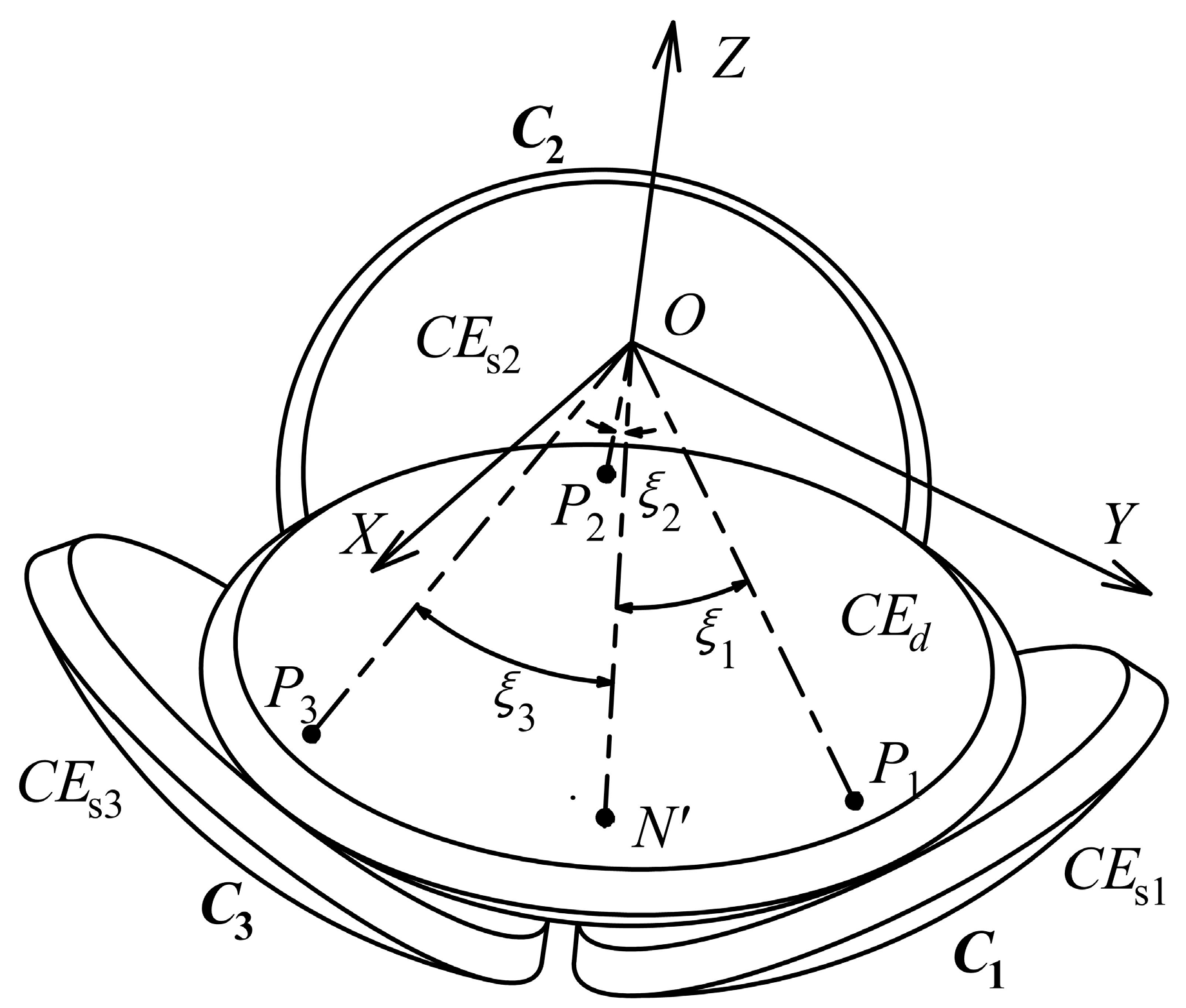
An area-varying capacitive sensor with a spherically coronal structure is proposed to detect the 2-DOF angular motions of a spherical joint, i.e., the rotations of the output rod about the
X- and
Y-axes, respectively. As shown in
Figure 2, the proposed capacitive sensor mainly includes four spherically coronal electrodes, i.e., an excitation electrode (
CEd) and three sensing electrodes (
CEsi,
i = 1, 2, 3). The excitation electrode is applied as a common electrode, which is concentrically attached to the lower surface of the ball of the spherical joint. The point
N denotes the intersection point of the central axis of the output rod and the outer surface of the excitation electrode
CEd, i.e., the center of the excitation electrode plate. Three sensing electrodes are concentrically fixed on the inner surface of the socket. Each sensing electrode (
CEsi,
i = 1, 2, 3) and the excitation electrode
CEd form a capacitor (
Ci,
i = 1, 2, 3). The central point of the inner surface of
CEs1,
CEs2, and
CEs3 is defined as
P1,
P2, and
P3, respectively. The main advantage of the spherically coronal electrodes is that it could avoid the effect of the rotation about the rod centerline on the detection of other 2-DOF angular motions. This is because the overlapping area of the excitation electrode plate and each sensing electrode plate remains unchanged as the output rod rotates around its own axis (
z-axis). Teflon-laced epoxy with self-lubricating and abrasion-resistant properties is used as a dielectric material, which is uniformly deposited on the surfaces of the spherically coronal electrodes. This would produce the insulation between the sensing electrodes and the excitation electrode, and improves the sensitivity of the sensor.
Initially, the output rod of the spherical joint is placed along the vertical direction, that is, the central axis of the output rod is aligned with the axis of the socket. Three capacitors C1, C2 and C3 have the same capacitance value. Once the output rod rotates about the X- and Y-axes, the effective overlapping area of the excitation electrode plate and each sensing electrode plate is varied, changing the capacitance values of each capacitor. Thus, the angles (ξ1, ξ2 or ξ3) between the centers of three sensing electrode plates and that of the excitation electrode plate could be calculated from the measured capacitance values of the capacitors C1, C2, and C3; then, the rotational angles (γ and β) of the output rod of the spherical joint about the X- and Y-axes could be obtained.
For the convenience of presenting the relation between three central angles and two rotational angles, it is assumed that three sensing electrode plates are uniformly distributed along the same latitudinal direction. Thus, the initial angle (
ρ0) between the center of each sensing electrode plate and that of the excitation electrode plate is equal to each other. As shown in
Figure 2, at the initial position, the coordinates of the point
N are (0, 0, -
r). As the spherical joint rotates by an
RPY angle (
γ,
β, 0), the point
N moves to point
N’. Consequently, the angles
ξ1,
ξ2, and
ξ3 are subtended by the arc
N’ P1,
N’ P2, and
N’ P3, respectively. They can be given by the following equations:
Using Equations (5) and (6), we obtain the following:
Using Equations (4), (5), and (7), we can derive the equation of the rotation angle
γ:
By substituting Equation (8) into Equation (7), we obtain the equation of the rotation angle
β:
Thus, according to Equations (8) and (9), the 2-DOF rotation angles (γ and β) of the spherical joint could be obtained, provided that the angles (ξ1, ξ2, or ξ3) could be calculated from the measured capacitance values of the capacitors C1, C2, and C3.
3.2. Mathematical Model of the Capacitive Sensor
To simplify the calculations of the capacitance values, we make the following assumptions: (1) the area element dS of spherically coronal plates is assumed as a parallel-plate capacitor with an equal separation distance d; (2) it is assumed that the gap d is much smaller than the dimensions of the plates; (3) the fringing effect of the capacitive plates is small enough to be ignored.
By integrating the capacitance formula for the plate capacitors, we can obtain the capacitance value of the spherical capacitors as follows:
where
ε is the permittivity of the dielectric material between the excitation electrode and the sensing electrode, while
Si denotes the effective overlapping area of the sensing electrodes (
CEsi,
i = 1, 2, 3) and the excitation electrode.
To approximately calculate the effective overlapping area of the sensing electrodes and the excitation electrode, we assume that the radius of the spherical capacitive plates is equal to that of the ball of the spherical joint (
r).
Figure 3 presents the mathematical model of the overlapping area of two spherically coronal capacitive plates, along with a fixed coordinate system
OXYZ and a moving coordinate system
oxyz. The spherical sensing electrode is fixed at the coordinate system
OXYZ with its central axis along the
Z-axis and the corresponding sphere center at the origin
O. The spherical excitation electrode is attached on the coordinate system
oxyz with its central axis along the
Z-axis and the corresponding sphere center at the origin
o. Two origin points
O and
o superpose each other. The curves
e1 and
e2 are the boundary of the sensing electrode and the excitation electrode, respectively. The plane
OP1P2, crossing through the origin
O and intersection points
P1 and
P2, separates the overlapping area of the two spherical electrodes into two parts, i.e.,
A1 and
A2. The curve
e3 is the intersection line of the plane
OP1P2 and the sphere. Initially, the two coordinate systems superpose each other. If the coordinate system
oxyz rotates about the
X-axis with an angle of
ψ, then the angle between the centers of two spherical capacitive plates is
ψ.
α1 and
α2 are the central angles of the sensing electrode and the excitation electrode, respectively.
The spherical area
Ai (
i = 1, 2) surrounded by the curve
ei (
i = 1, 2) and the curve
e3 can be calculated as follows:
where
,
,
,
.
Then, the effective overlapping area of two spherical electrode plates can be obtained as follows:
According to Equations (11) and (12), the effective overlapping area of the excitation electrode and the sensing electrode has a relation with the angle
ψ, which can be defined as follows:
Considering the special structure of the spherical joints, the boundary of the excitation electrode should not move beyond equatorial plane of the socket when the excitation electrode rotates by the maximal angles. Thus, the central angle
α2 of the excitation electrode should satisfy the condition of
α2 ≤ 45°. On the other hand, the large overlapping area of the capacitive plates could improve the sensitivity of the sensor. Hence, we have
α2 = 45°. To avoid the structure interference of three sensing electrodes, we choose
α1 = 30°, and
ρ0 = 37°. As
ψ varies from 27° to 47°,
g(
ψ) can be fitted into linear function
g’(
ψ) with the maximum relative error of 0.467%. The fitting function is given as follows:
Then, by using Equations (10)–(14), the capacitance value of the capacitor can be expressed by:
Thus, the relation between the capacitance value of each capacitor and the angle ψ between the centers of two capacitive plates is established. In other words, the angles (ξ1, ξ2 or ξ3) between the centers of three sensing electrode plate and that of the excitation electrode plate could be calculated from the measured capacitance values of the capacitors C1, C2 and C3.
4. Simulation Setup
To validate the feasibility of the proposed method, the proposed capacitive sensor was simulated using Ansoft Maxwell. In the practical applications of capacitive sensors, the electric-field lines bend at the edge of the capacitive plates, resulting in the additional capacitance [
18]. This phenomenon is referred to as the fringe effect, which could reduce the sensitivity of the sensor and produce nonlinear errors [
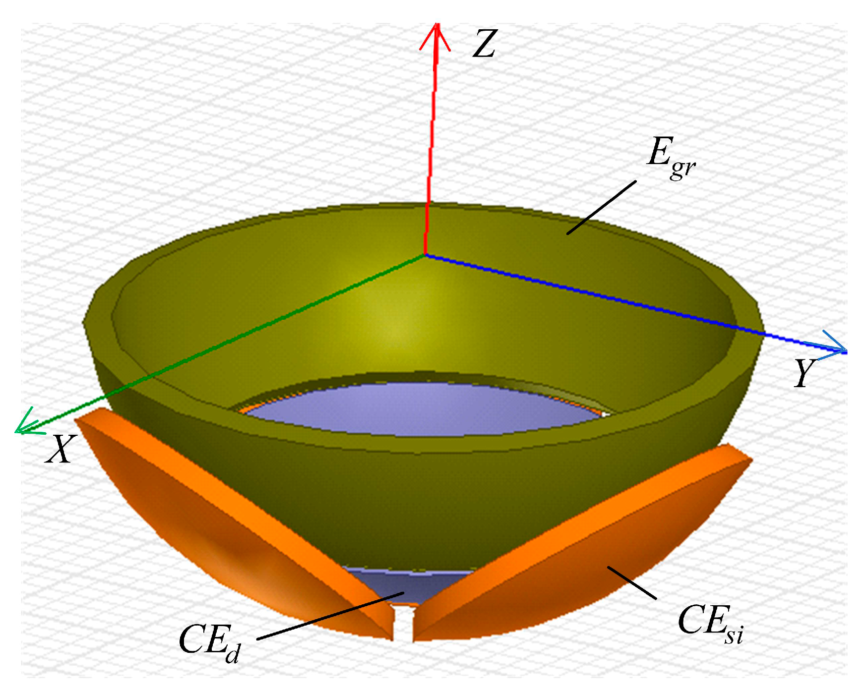
19]. Thus, the guard ring (
Egr) was set around the spherical capacitive electrodes to reduce the fringe effect on the output of the capacitive sensor.
Figure 4 presents the simulation model of the capacitive sensor. It consists of an excitation electrode, a guard ring, and three sensing electrodes. The air was used for the dielectric material between the capacitive plates to simplify the simulation model. The structural parameters of the capacitive sensor are shown in
Table 1. It should be pointed out that the electromagnetic shield should be considered in the practical applications. Specifically, in order to reduce the external interference from other metal structures and the environmental noise, the sensing electrodes are shielded by the grounded shell and guard ring, and a dielectric material is placed between the excitation electrode and the ball of spherical joints.
The simulated and theoretical capacitance values of the capacitors
C1,
C2 and
C3 were compared in detail to validate the feasibility of the proposed method. In the simulation, we assume that the spherical excitation electrode (
CEd) firstly rotates by an angle
γ about the
X-axis, and then rotates by an angle
β about the
Y-axis. The capacitance values of three capacitors with and without the guard ring
Egr are calculated by Ansoft Maxwell. For the theoretical calculation, the angles (
ξ1,
ξ2 and
ξ3) of the capacitive plates can be obtained by substituting the simulation values of
β and
γ into Equations (4)–(6). Then, the capacitance value of three capacitors can be calculated according to Equations (8)–(12). Four cases are examined in this work; that is, the output rod of the spherical joint rotates about the
X-axis before rotating about the
Y-axis, and the corresponding rotational angles (
γ and
β) are shown in
Table 2.
5. Results and Discussions
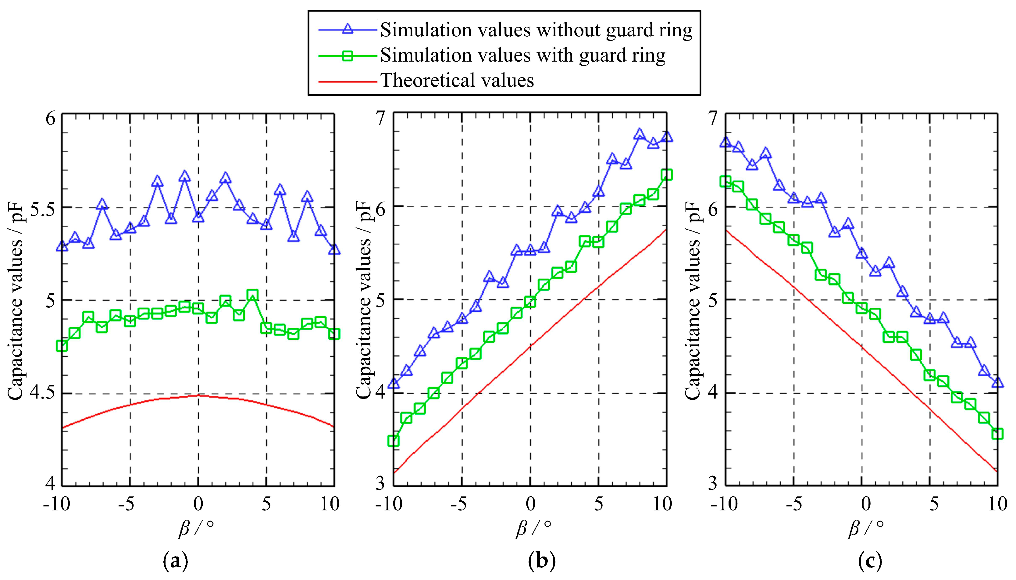
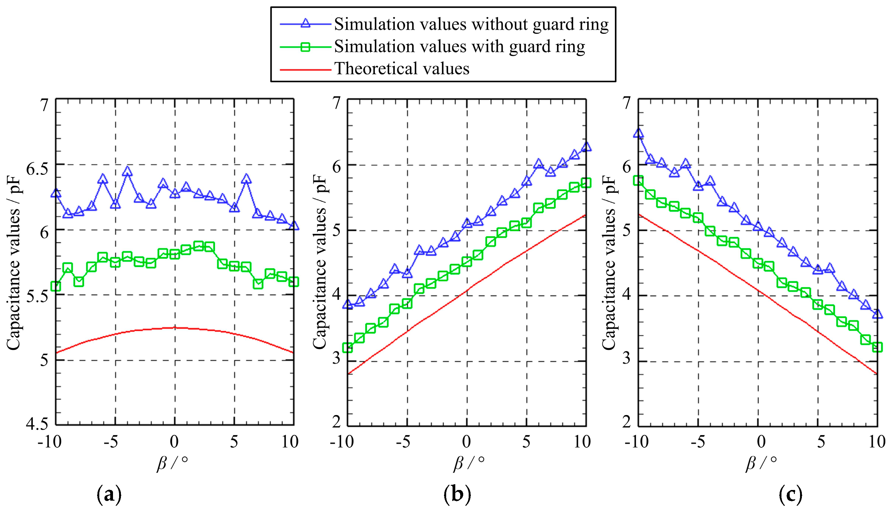
Figure 5 presents the capacitance variation of three capacitors as the spherical excitation electrode rotates about the
Y-axis. Specifically, the rotation angle
γ equals to zero while the rotation angle
β varies from −10° to 10° with a step of 1°. Several observations can be made. First, the variation of the simulated capacitance values of the capacitors
C1,
C2, and
C3 exhibits a similar trend with that of the theoretical values. Second, the simulated values are larger than the theoretical counterparts, which can be ascribed to the fringe effect [
19,
20]. Third, the simulated values can be reduced by using the guard ring. Four, the capacitance values of the capacitors
C2 and
C3 exhibit a linear relation with the rotation angle. As the rotation angle
β increases, the capacitance value of
C2 rises gradually, while the capacitance value of
C3 reduces.
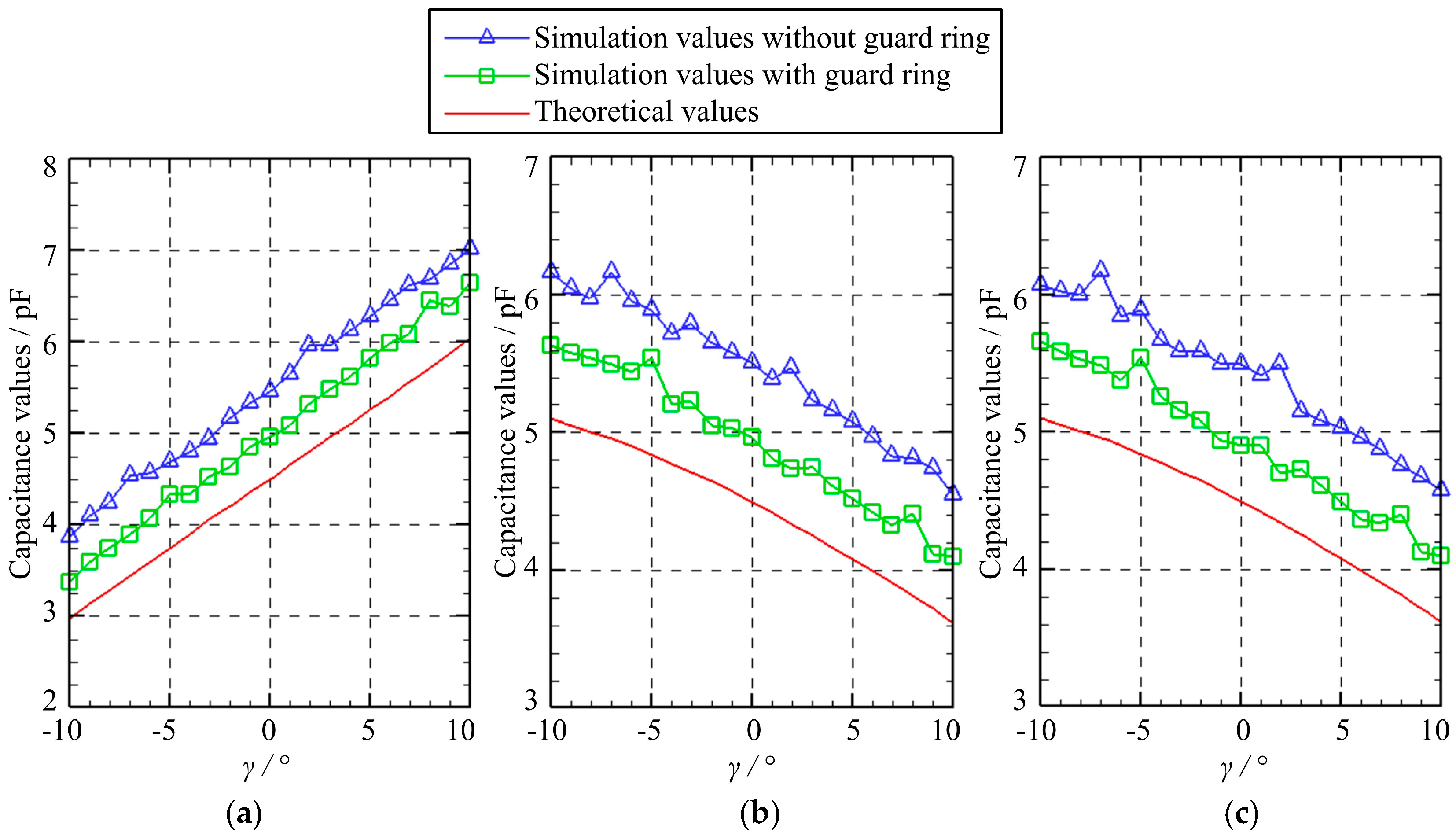
Figure 6 presents the capacitance variation of three capacitors as the spherical excitation electrode rotates about the
X-axis. Specifically, the rotation angle
γ varies from −10° to 10° with a step of 1°, while the rotation angle
β equals to zero. Three observations can be made. First, the simulated capacitance values of the capacitors
C1,
C2, and
C3 exhibit a similar variation tendency with the theoretical values. Second, compared with the theoretical values, the simulated ones exhibit an increase of approximately 1 pF, which can be suppressed by using the guard ring. Third, the capacitance values of the capacitors
C1,
C2 and
C3 exhibit a roughly linear relation with the rotation angle. With the rise in the rotation angle
γ, the capacitance value of
C1 increases gradually, while the capacitance values of
C2 and
C3 decrease.
Figure 7 presents the capacitance variation of three capacitors as the spherical excitation electrode rotates about the
X-axis before rotating by a fixed angle of
β = 5° about the
Y-axis. The rotation angle
γ about the
X-axis varies from −10° to 10° with a step of 1°. Several observations can be made. First, the variation of the simulated capacitance values of the capacitors
C1,
C2, and
C3 is similar to that of the theoretical values. Second, the simulated values with the guard ring are smaller than those without the guard ring, but larger than the theoretical ones. Note that the fringe effect is neglected in the theoretical calculations; thus, it indicates that the guard ring could reduce the fringe effect that occurs in the simulation. Third, as the rotation angle
γ increases, the capacitance value of
C1 goes up linearly while the capacitance value of
C2 and
C3 drops gradually.
Figure 8 presents the capacitance variation of three capacitors as the spherical excitation electrode rotates by a fixed angle of
γ = 5° about the
X-axis before rotating about the
Y-axis. The rotation angle
β about the
Y-axis varies from −10° to 10° with a step of 1°. It can be seen that the variation of the simulated capacitance values of the capacitors
C1,
C2, and
C3 shows a similar tendency with that of the theoretical values. However, the theoretical capacitances exhibit smaller values of about 0.5 pF and 1 pF than the simulated counterparts with and without the guard ring, respectively. It should be noted that the capacitance values of the capacitors
C2 and
C3 exhibit a linear relation with the rotation angle about the
Y-axis. The capacitance of
C2 rises gradually, while the capacitance of
C3 reduces with the increasing angle
β.
In summary, the variation of the simulated capacitance values of the capacitors exhibits a similar trend with that of the theoretical values. This suggests the feasibility of the proposed method. Note that the proposed sensor consists of three sensing electrodes, which are used for the detection of the angles about the X- and Y-axes. One may wonder the reason for the adoption of three instead of two or four sensing electrodes. Some reasons are proposed as follows. If two sensing electrodes are placed in the X- and Y-axes, they could detect the rotational angles about the Y-axis and X-axis, respectively. However, the angular motion of the spherical joints in practical applications is very flexible. If the rotation axis is perpendicular to the X–Y plane, the change in the overlapping area of the spherical plates is relatively small, which would lead to a low sensitivity in the angular motion in the X–Y plane. To avoid this drawback, the number of the sensing electrodes should be increased. In this work, three sensing electrodes are distributed axisymmetrically; that is, each electrode is located in the symmetric axis of the other two. As a result, the angular motion in the symmetric plane of each two sensing electrodes can be detected by the third one. Four capacitors could form differential capacitance, which may increase the sensitivity of the sensor. However, there may be the same problem as in the case of two sensing electrodes. In addition, the area of each electrode would be smaller to avoid the structural inference between the sensor and the spherical joint. This may have an effect on the sensitivity of the sensor. Thus, a detailed examination of measurement sensitivity and the structural inference for four sensing electrodes will be made in future works. In fact, we tend to believe that six or more sensing electrodes may be beneficial to achieve the differential capacitance detection.

 ,
, 


