Validation of a New Quality Assessment Procedure for Ductile Irons Production Based on Strain Hardening Analysis


1
Department of Chemical Sciences and Materials Technology, Institute of Condensed Matter Chemistry and Technologies for Energy (ICMATE), National Research Council of Italy, via R. Cozzi 53, 20125 Milano, Italy
2
Zanardi Fonderie S.p.A., via Nazionale 3, 37046 Minerbe (VR), Italy
*
Author to whom correspondence should be addressed.
Metals 2019, 9(8), 837; https://doi.org/10.3390/met9080837
Submission received: 19 June 2019
/
Revised: 22 July 2019
/
Accepted: 24 July 2019
/
Published: 27 July 2019
(This article belongs to the Special Issue Failure Mechanisms in Alloys)
Abstract
:A mathematical procedure based on the analysis of tensile flow curves has been proposed to assess the microstructure quality of several ductile irons (DIs). The procedure consists of a first diagram for the assessment of the ideal microstructure of DIs, that is, the matrix where mobile dislocations move, and a second diagram for the assessment of the casting integrity because of potential metallurgical discontinuities and defects in DIs. Both diagrams are based on the dislocation-density-related constitutive Voce equation that is used for modeling the tensile plastic behavior of DIs. The procedure stands on the fundamental assumption that the strain hardening behavior of DIs is not affected by the nature and the density of the potential metallurgical discontinuities and defects, which are expected to affect only the elongations to fracture. However, this fundamental assumption is not obvious, and so its validity was evaluated through tensile testing Isothermed Ductile Irons (IDIs) 800, showing a wide scatter of elongations to rupture. The analysis of the strain hardening behaviors supported by strain energy density calculations of IDIs tensile tests proved that the fundamental assumption was valid and the quality assessment procedure could be applied to IDIs. A modified Voce equation was also introduced to improve the fitting of the experimental tensile flow curves and the strain energy density calculations.
1. Introduction
Due to the demand of improving mechanical properties, new chemical compositions and production routes of Ductile Irons (DIs) have been explored to obtain different microstructures. Thus, new classes of advanced DIs have been produced, that are, for instance, the alloyed SiBoDur [1] and High Silicon Strengthened (HSiS) DIs, i.e., with silicon content above 3.5–4.0 wt% [2,3,4], and the Austempered DIs (ADIs) [5,6,7,8] and Isothermed DIs (IDIs) [8] that are produced through heat treatments. The current international standards were originally produced for classifying conventional DIs, where silicon content is almost constant (1.8–2.8 wt%) and the pearlite to ferrite ratio, changing because of alloying elements like copper, is the key microstructure parameter that increases yield and tensile strengths, and reduces elongations to rupture. Thus, the current DIs classification is based on the minimal tensile mechanical properties, but unfortunately this classification cannot give the correct picture of the advanced DIs [9]. A specific classification approach to properly weigh up these new generations of advanced DIs is needed, which should be capable of taking into account increasing alloying elements content and new production routes, mainly through heat treatments resulting in complex microstructures, like ausferrite in ADIs and perferrite in IDIs.
Microstructure in DIs and any castings may enclose metallurgical discontinuities and defects that cause high variability in mechanical properties. To minimize this variability metallurgical discontinuities and defects have to be easily evaluated, hopefully based on tensile data [10]. Microstructure is a generic term that involves different structural features at different scales. However, only those structural features that produce effects because of the application of some external stimulus are meaningful to define the microstructure of materials. Under the experimental conditions to test metallic materials in tension, in ferritic-pearlitic DIs or perferritic IDIs, bcc ferrite deforms plastically through dislocation multiplication and storage, and motion of mobile dislocations. Therefore, as the correlation between microstructure and tensile plastic behavior is our concern, dislocation dynamics has to be considered. At room temperature, dislocations move on crystallographic planes along specific crystallographic directions of bcc ferrite, and interact with other structural features that they encounter on these planes, and are obstacles to their motion, i.e., other dislocations, grain boundaries, and second phases boundaries, like α/cementite interfaces in pearlite. The set of the structural features involved in this scenario results in what is called as the matrix. The matrix and the loading conditions (loading mode, strain rate, and temperature) determine the plastic flow curves of metallic materials. However, metallurgical discontinuities and defects that in DIs are irregular morphology graphite, shrinkages, slag inclusions, and gas holes, may be present in the matrix and affect the tensile flow curves, the extent of which depends on their nature and density. The microstructure results in matrix with metallurgical discontinuities and defects. In the contest of cast products, quality mainly assumes the meaning of microstructure integrity, that is, the absence of metallurgical discontinuities and defects. The microstructure is of high quality or ideal, when the nature and density of defects in the matrix are below a threshold and do not affect the flow curve; in other words, the ideal microstructure is the matrix. Otherwise, when defects affect the flow curve to some extent with respect to the flow curve of the ideal microstructure, the microstructure is defected or of lower quality.
A framework to classify grade (conventional and heat treated) and quality level of DIs based on plastic properties has been proposed by Zanardi et al. [9], where a Material Quality Index (MQI) was defined as
with Rm the ultimate tensile strength, and A5 the elongation to rupture in tensile test. Accordingly, new generation DIs have MQI larger than 360, while in conventional ferritic-pearlitic DIs MQI ranges between about 100 and 190 according to the pearlite content. Indeed, a first MQI was first proposed by Siefer and Ortis, and developed later by Crews in 1974 [10], defining MQI = Rm2·A5. However, an effective microstructure quality assessment procedure should be capable of cataloguing univocally the grade of the matrix (the ideal microstructure), depending on chemical composition and production route, and within that, of classifying the integrity of the material, which these approaches based on MQIs cannot do. An innovative mathematical procedure [11,12] to assess the microstructure quality of DIs has been recently proposed and it is indeed capable of addressing these two issues: Cataloguing different grades of DIs and classifying their integrity. The procedure comes into two diagrams. The first diagram is for the assessment of DIs matrix, that is, the ideal microstructure. This first diagram is based on the correlation between matrix and plastic behavior, which can be described by using the dislocation-density-related constitutive Voce equation. In fact, the Voce equation parameters obtained from the best fits of the experimental tensile flow curves are used as coordinates of the matrix assessment diagram. Conventional DIs with different ferrite–pearlite ratios and advanced DIs with high silicon content or ausferrite and perferrite, are univocally identified by lining on distinct positions on it [11,12]. Thus, the diagram can classify the different microstructures of the modern DIs, overtaking the limitations of the current classification standards based on the minimal mechanical properties and MQIs. The second diagram is for the material integrity assessment, and is also based on Voce formalism. Metallurgical discontinuities and defects can cause premature rupture that occurs before the geometrical instability of tensile specimens, that is, localized deformation (necking), and so in the integrity assessment diagram the experimental elongations to rupture (er) and uniform elongations (eu) where necking occurs, are compared [11,12].
MQI = Rm2·A5/(8200 + 3Rm),
A similar approach has been published to assess the integrity of Al casting alloys for aerospace applications, based on the concept of the target properties [13,14] by using Voce equation and Strain Energy Density (SED) that is the energy per unit volume stored during tensile plastic deformation until rupture. In the reported tests on Al casting alloys, the strain hardening behavior was significantly affected by metallurgical discontinuities and defects, because of the pour integrity typical in Al castings, which made it difficult to define a specimen free of major defects, and in fact the target properties approach has been discarded for a statistical approach based on the ductility potential [15,16]. Indeed, the two diagrams procedure here proposed to assess the microstructure quality of DIs stands on the fundamental assumption that the strain hardening behavior of DIs is not affected by the nature and the density of the potential metallurgical discontinuities and defects, which are expected to only affect the elongations to fracture. However, this is not obvious, as already reported in Al castings [13,14,15,16], and if the assumption were not valid, the integrity assessment diagram for DIs should be abandoned. This paper is focused on evaluating whether, in DIs, the metallurgical discontinuities and defects only affected the elongations to rupture, and did not the strain hardening behavior. As a consequence of this validation, the mathematical procedure proposed for the material quality assessment of DIs [11,12] should be validated.
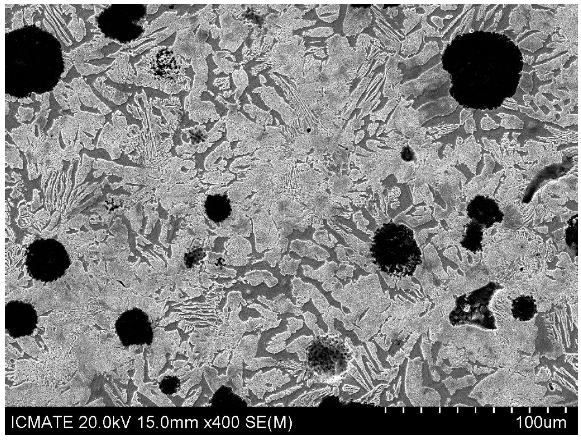
For this investigation, the heat treated IDIs 800 (Ultimate Tensile Strength—UTS—of 800 MPa) produced in Zanardi S.p.A. was used, intentionally selected in a wide range of elongations to rupture before and after necking, which was not typical for this material grade that is usually characterized by an improved uniformity of mechanical properties, thanks to the absence of any alloying and for a short time for the solid state transformation during quenching after partial austenitization. Isothermed Ductile Irons (IDIs) [17] belong to a new generation of DIs that are very attractive for the good combination of outstanding mechanical properties and low production costs. IDI 800s were produced from conventional GJS 400 heats (with a C content of about 3.6wt% and Si 2.46–2.66, Mn 0.10–0.15, Cu 0.01–0.15, Ni < 0.06, Mo < 0.01, and Sn < 0.01, Fe balance) that were cast with different cooling rates in Zanardi Fonderie S.p.A. through four different mold geometries, namely, cylindrical Lynchburg mold with 25 mm diameter (here after L25) produced complying with the standard UNI EN 1563, and three different Y moulds with thickness 25, 50 and 75 mm (here after Y25, Y50 and Y75) complying with the standard ASTM A 536-84. Then, from room temperature the GJS 400 heats were heated up at 815 °C in the intercritical range Ac1–Ac3 for 150 min [17] to be partially austenitized, leaving an opportune fraction of pro-eutectoid ferrite, and then, after quenching in salt bath above the Ms, the austenite transformed into pearlite. The resulting microstructure is called as perferrite (that is a neologism [9]) and consists of alternated ferrite and pearlite, which is different from the bull-eye structure of conventional pearlitic-ferritic DIs, where ferrite is surrounded by pearlite. The microstructure of alternated ferrite and pearlite confers, to IDI 800, excellent elongations to rupture, and in fact the minimum elongation to rupture is 6% for IDI 800, while it is 2.5% for conventional pearlitic-ferritic grades with UTS of 800 MPa [9]. An example of perferrite is reported in Figure 1, where pearlite is bright (volume fraction typically higher than 60%), ferrite is gray and graphite is black (volume fraction typically 10%). Microstructure observations of IDI 800 were performed through a high resolution Scanning Electron Microscope (SEM) SU-70 by Hitachi (Hitachi High-Technologies Corporation, Tokyo, Japan) after conventional metallographic polishing procedure and final etching with Nital 2%.
The wide range of elongations of the 20 tensile-tested samples of the investigated IDI 800 was associated either to a wide range of density of possible metallurgical discontinuities and defects, and to the ideal matrix when uniform elongations were achieved. The strain hardening behaviors of the tensile curves of IDIs 800 were analyzed, and the fundamental assumption of the quality assessment procedure was quantitatively analyzed on strain hardening comparison and SED considerations.
2. Methods
2.1. Mechanical Properties and Plastic Behaviour
Tensile tests were carried out at the strain rate of 10−4 s−1 on round specimens made of 20 different IDI 800 samples with an initial gauge in the diameter do = 12.5 mm and length lo = 50 mm complying with ASTM E8-8M. Engineering tensile flow curves S vs. e with S = F/Ao and e = (l − lo)/lo were obtained, where F, Ao and l were the instantaneous load, the initial sectional area and instantaneous gauge length, respectively. The mechanical properties that are conventionally used to qualify metallic materials are Yield Stress (YS), Ultimate Tensile Stress (UTS), and elongation to rupture (er). These parameters are correlated with the material microstructure. However, they are not enough to assess the microstructure quality, since the uniform elongation eu is also relevant. In fact, plastic deformation lastly induces failure, and in tensile testing strain localization in the form of necking occurs: The elongation at necking is called uniform elongation (eu). Metallurgical discontinuities and defects are stress raisers that can nucleate cracks and produce premature failure before necking, causing er < eu, and so eu is a parameter that can give indications of the quality of the material microstructure.
A rigorous method to find the uniform elongation eu and compare it to the experimental elongation to rupture er is based on two steps. First, true stress-true plastic strains (σ vs. εp) have to be found, where σ = S·(1 + e) and εp = ε − σ/E = ln(1 + e) − σ/E, with S and e the engineering stress and elongation, respectively, and E the experimental Young modulus obtained from tensile tests. Secondly, an appropriate constitutive equation [18,19,20] has to be used to model the experimental flow curves to predict, at best, the uniform strain εu, that is, the plastic strain at which the Considère’s condition dσ/dεp = σ is fulfilled, where dσ/dεp is the strain hardening rate. Note that the uniform strain εu is univocally linked to the uniform elongation eu, as well as, the strain to rupture εr is related to the elongation to rupture er. However, since height and shape of tensile flow curves could be affected by the nature and the density of defects, a straightforward comparisons between er and eu might be meaningless, and the effects of defects on strain hardening behavior of DIs, that is the increase of strength with straining, necessarily has to be analyzed.
2.2. Voce Equation
Voce equation is
where σ is the true flow stress, εp the true plastic strain, σV is the saturation stress that is achieved asymptotically with straining, εc is the characteristic transient strain that defines the rate with which σV is approached, and σo is the back-extrapolated stress to εp = 0. Voce equation has been successfully applied to a wide number of metallic materials, like copper [18,19], austenitic stainless steels [21,22], aluminum alloys [13,14,15,16], ferritic-pearlitic DIs, IDIs, and ADIs [8,9,11,12], and also solid solution and precipitation strengthened nickel based superalloys [23].
The differential form of the Voce equation is used to investigate the strain hardening behavior of IDIs:
where Θo and εc are constants. Through fitting Equation (3) to the linear regions at high stresses in the differential experimental data (dσ/dεp vs. σ), the Voce parameters Θo and εc are found, and, as a consequence, σV. Finally, σo is found from the best fitting of Voce equation to the experimental tensile flow curves.
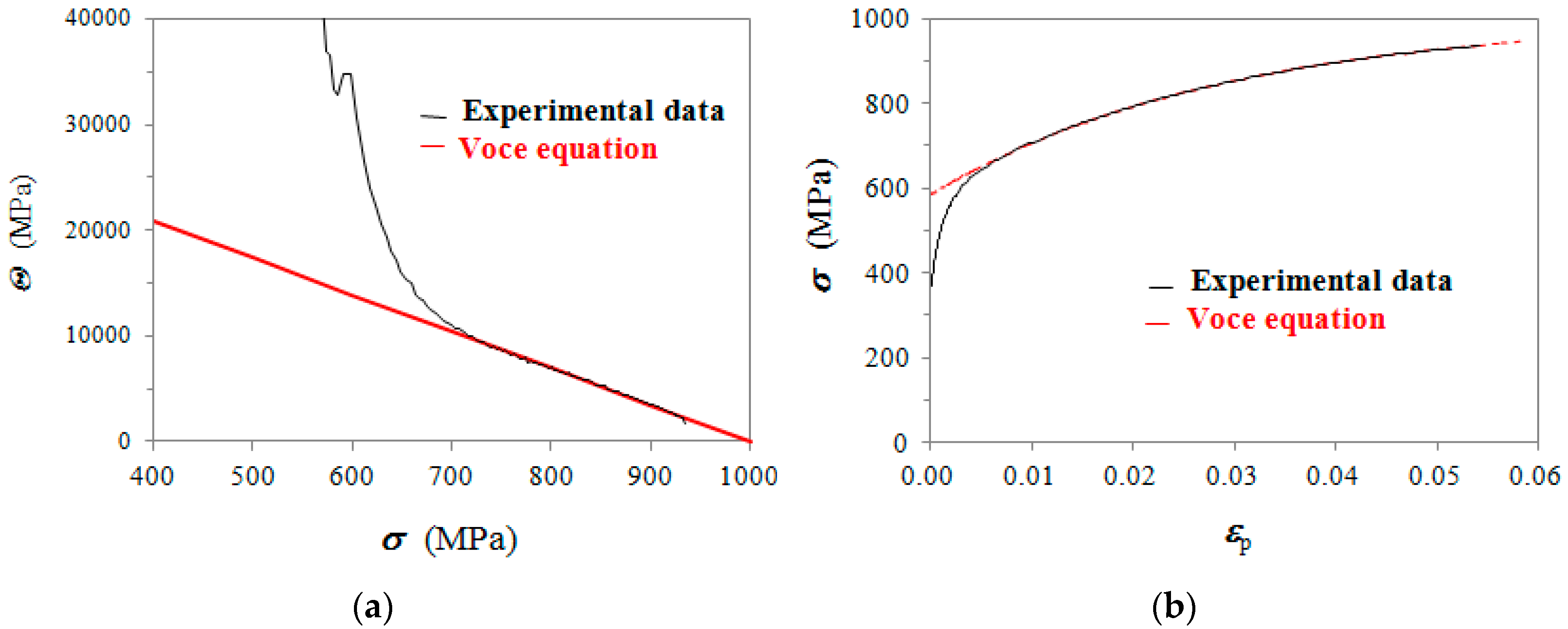
In Figure 2, an example of fitting procedure on a typical IDI 800 is reported (sample No. 18 in Table 1). In Figure 2a, where data dσ/dεp (= Θ) vs. σ are reported, the slope of the best linear fit at high stresses is 1/εc, whilst Θo is the intercept with σ = 0 according to Equation (3). In Figure 2b, the corresponding tensile flow curve with the best fitting Voce equation with the parameters found in Figure 2a are reported. The saturation stress is σV = Θo∙εc, and σo is found through minimizing the variance between Voce equation and experimental data. The first diagram of the material quality assessment procedure is for the assessment of the IDI ideal matrix and is based on plotting 1/εc vs. Θo.
For the definitions of the second diagram concerning the casting integrity, which is for the assessment of metallurgical discontinuities and defects, the uniform strain εu,p is defined according to Voce formalism as follows:
It is important to bear in mind that εu,p was determined from Voce parameters, independently of the fact that necking was actually achieved or not. Indeed, if necking was achieved, then εu,p could be compared to the actual uniform elongation εu,exp, found experimentally at necking. However, if necking did not occur, then εu,p was the ideal value that was not achieved because of metallurgical discontinuities or defects. Then, the uniform elongation is
where σu is the stress at εu,p, E the experimental Young modulus, and σu/E is the elastic component of strain. The second diagram concerning the casting integrity was built by plotting the experimental elongations to rupture er vs. eu, that is the ideal uniform elongations.
2.3. Strain Energy Density (SED) at Uniform Strain
In order to compare the strain hardening behavior of two samples quantitatively, the only comparison of the Voce parameters coming from strain hardening analysis (1/εc and Θo) might not be enough, since the yielding where dσ/dεp varied rapidly, could not be easily compared in the dσ/dεp = Θ vs. σ plots. Thus, we proposed that a third parameter should be involved in strain hardening comparisons, which was the plastic SED at the uniform strain εu,p, hereafter called as SEDU, that is the volumetric plastic strain energy (MJ/m3) stored in the tensile sample up to the uniform strain εu,p, defined as
where σ(εp) was the Voce equation (see Equation (2)). εu,p depended on Voce parameter σo (see Equation (4)), that is close to the yielding proof stress σ0.2%. SEDU had the advantage to be an integral quantity involving the whole plastic flow curve, and furthermore SEDU was particularly useful to compare the plastic behaviors of ideal matrix, where εu,p was indeed achieved (er ≥ eu) and defected material where εu,p was not (er < eu).
In Figure 2b, Voce equation matches very well the experimental flow curve only at high strains. The reasons of this mismatch could be attributed to a transient in the dislocation microstructure evolution and are debated [19]. However, for the determination of SEDU in Equation (6) proper modeling of the tensile flow curve was also necessary at small strains. A negative Ludwigson-kind correction ∆ was proposed to the Voce equation, which was meant to also match the experimental flow curve at small strains:
with σ1 = 1 MPa (inserted for dimensional consistency), and n0, n1 and n2 constants obtained from fitting. So the modified Voce equation used to model the IDI 800 experimental flow curves was finally
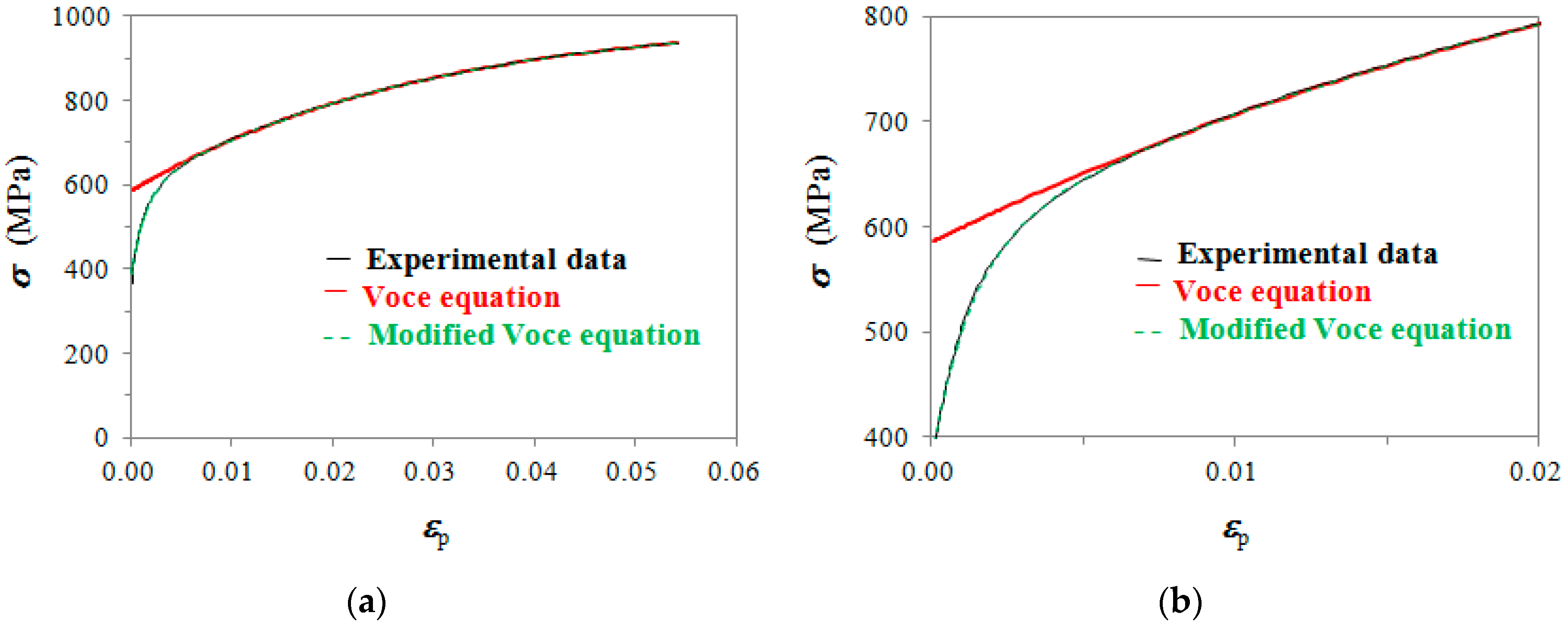
In Figure 3 an example of the best fitting with Equation (8) of the same tensile flow curve in Figure 2b (sample No. 18 in Table 1) is reported. The match is excellent all over the strains. For instance, at εp = 0.002 the error was 8.1% with Voce equation, while the error was reduced at −0.2% with the modified Voce equation (Equation (8)).
3. Results
3.1. Microstructure Quality Assessment Procedure
The Voce parameters Θo and 1/εc resulting from the strain hardening analysis of the IDI 800 tensile flow curves are reported in Table 1, with increasing Θo in order to help the data interpretation. Uniform plastic strains εu,p (Equation (4)), uniform elongations eu (Equation (5)) and er/eu ratios are reported for rupture conditions analysis, and SEDU values (Equation (6)) calculated using the modified Voce equation (Equation (8)) data for strain hardening comparison purposes. The mold types are also reported for indication of the cooling rates of the GJS 400 heats from which the IDIs 800 were produced, the fastest with L25 mould and the slowest with Y75 mold. The nodule counts measured complying on the standard ASTM E 2567 resulted to be 420 nodules/mm2 in L25, 280 in Y25, 190 in Y50 and 150 in Y75, and pearlite ranged between nil and 5%, which was typical of fully ferritic grade GJS 400. In Table 1, there was no correlation between molds (cooling rates) and plastic behavior, namely Voce parameters. This is distinctive of IDIs because of their low alloying elements contents. In fact, in IDIs, there are no major segregations that may be particularly significant and detrimental in thicker walls when the alloying elements content is higher. However, the aim of the work was not to find a stringent correlation between Voce parameters and microstructure that was not investigated through quantitative techniques, but was to evaluate the goodness of the quality assessment procedure [11,12] on a IDI grade that could present a wide range of final elongations. This variability might be associated either to a wide range of density of possible metallurgical discontinuities and defects, or to an ideal matrix when uniform elongations were achieved. Thus, the set of 20 samples of IDIs 800 was intentionally selected in a wide range of elongations to rupture before and after necking, which was not typical for this material grade that is usually characterized by an improved uniformity of mechanical properties, thanks to the absence of any alloying and to the short time for the solid state transformation during quenching after partial austenitization.
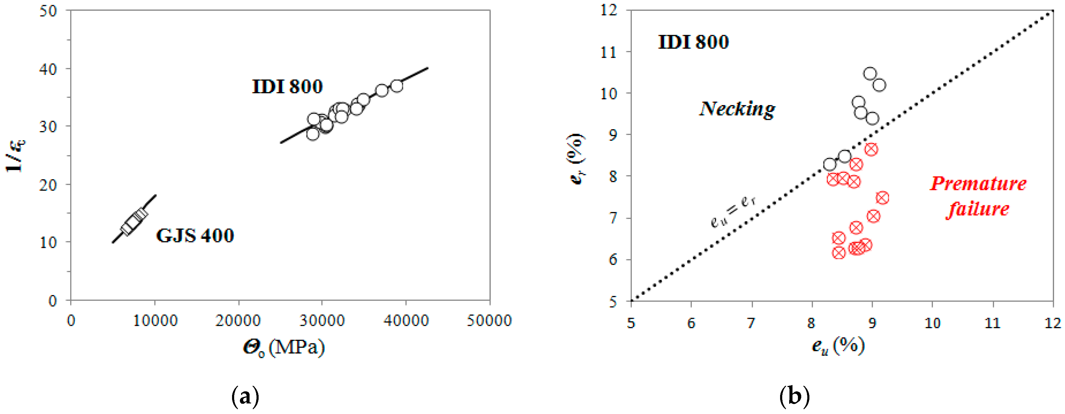
The matrix assessment diagram for IDI 800 is reported in Figure 4a, where GJS 400 data (different from the heats used to produce the investigated IDI 800) are also reported for comparison. GJS 400 was also produced in Zanardi Fonderie S.p.A. with L25, Y25, Y50, and Y75 molds, and presented a microstructure consisting of ferrite with a pearlite volume fraction spanning from nil to about 4% depending on the cooling rate. Each material lies on specific regions of the diagram along specific lines, identifying univocally the material in the diagram. The matrix quality assessment diagram is capable of classifying the different microstructures of the modern DIs produced with different chemical compositions (mainly the Si content) and through different industrial routes and heat treatments, like IDIs and ADIs [11,12]. In fact, the current classification standards are only based on the minimal tensile properties (yield stress, ultimate tensile stress, and ductility) that are sufficient to classify only the conventional DIs produced through a single process, where the only key microstructure parameter is the pearlite volume fraction. The integrity assessment diagram is reported in Figure 4b for IDI 800, where GJS 400 data are not reported since the ratios er/eu were always bigger than 1.5. For each tensile curve the experimental plastic elongations er with the ideal uniform plastic elongations eu (Equation (5)) were compared, where eu represented the ideal behavior of metallic materials, since necking was achieved. However, because of metallurgical discontinuities or defects premature ruptures could occur, resulting in plastic elongations er < eu. Thus, in Figure 4b, the data points below the ideal behavior line (er = eu) identify premature ruptures because of metallurgical discontinuities and defects, while data points lining on it or above (elongations beyond the necking) identify samples with metallurgical integrity. IDI 800 shown a wide range of possible rupture conditions for the selected set of test specimens IDI 800, so IDI 800 represented the optimal material for the present investigation.
3.2. Strain Hardening Comparison
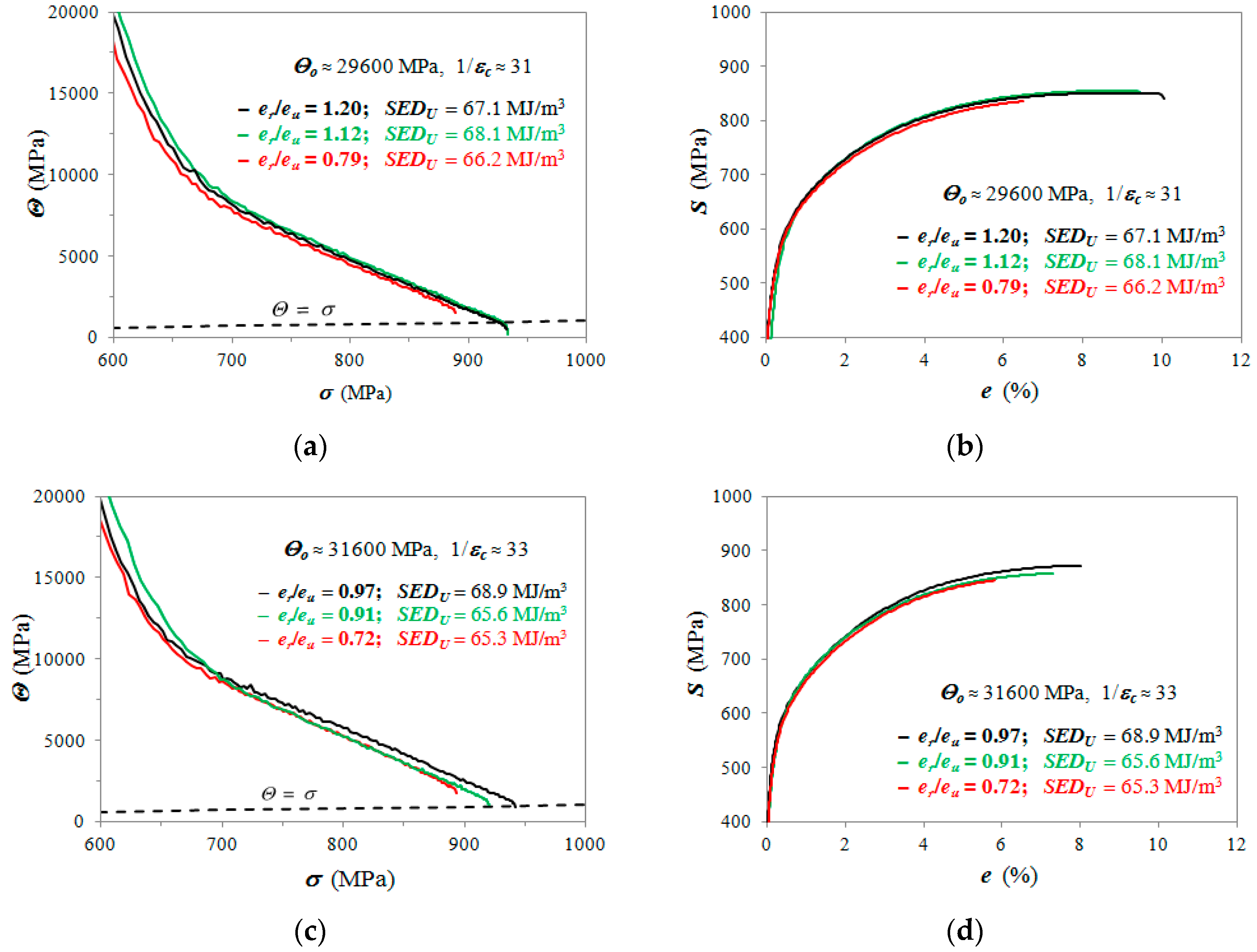
In Figure 5a,c,e, strain hardening plots Θ vs. σ of typical IDI 800 flow curves with similar Voce parameters and different er/eu ratios are reported for comparison. The Voce parameters were selected in order to span the full possible range of Θo. Indeed, to compare the strain hardening behavior, a third parameter was necessary, because yielding of different samples could be different even if the Voce parameters matched, and for this purpose SEDU were calculated in Table 1 and was reported in the plots of Figure 5. The dot lines passing through the origin in Figure 5a,c,e represent the Considère’s criterion, that is, the achievement of the uniform strain εu,p, i.e., the ideal behavior (necking). In Figure 5b,d,f, the engineering flow curves S vs. e corresponding to the strain hardening data in Figure 5a,c,e are reported. The differential data with similar Voce parameters and SEDU overlap whatever er/eu ratios they have, and so no significant change in the strain hardening behavior could be observed, even if significantly different rupture elongations were found: In Figure 5b er spans from a minimum of ≈6.5% to a maximum of ≈10%, while in Figure 5d,f from ≈6% to ≈8%. In other words, the tensile engineering flow curves matched utterly from yielding until the premature ruptures in the defected matrixes.
4. Discussion
Through the matrix assessment diagram in Figure 4a, different grades of DIs with different silicon content and different production routes involving heat treatments could be classified unambiguously. This is true for ferritic, ferritic-pearlitic DIs, ADIs 800 and 1000, and IDIs 800 and 1000 [11,12]. This capability is fundamental for a new classification approach needed for the appearance on the market of new advanced DIs, since the actual classifications of DIs are based on minimal tensile mechanical properties, and they are shaped on a single production route with similar silicon content, i.e., between 1.8–2.8 wt%, where pro-pearlite elements, like, for instance, copper, determine the pearlite to ferrite ratio and so yielding, tensile strength, and ductility. The integrity assessment diagram gives hint on the presence of metallurgical discontinuities and defects that reduce the material ductility. Indeed, the integrity assessment diagram is a graphical representation of the quality index er/eu that has some similarity with the approach presented by Caceres on Al castings [24], who has defined a relative ductility parameter q as
where er has the usual meaning, and er,mdf is the elongation to rupture of a major-defect-free specimen (subscript mdf). For er,mdf the strain hardening exponent n in the constitutive Hollomon equation, σ = K∙εn, was used, where K is the strength coefficient (MPa). Equation (9) is the ratio of extrinsic to intrinsic elongations, where extrinsic elongation is measured in the defected matrix, while the intrinsic one is from the ideal matrix free of defects. There are two major differences between Caceres’ approach and the here-proposed one. Firstly, the Voce equation has been proved to be more reliable on fitting tensile flow curves and determining the uniform elongations [8,19,20]. In Reference [8], it has been reported that theoretical uniform strains εu,p and the experimental εu,exp matched very well in IDIs and ferritic-pearlitic DIs with errors between experimental and theoretical values between 1% and 4%, if Voce formalism was used, in opposition to other constitutive equations, like Hollomon and Hollomon-type equations, where deviations between 50 and 100% were found. Secondly, in the here-proposed approach, the er,mdf is calculated by the Voce parameters found from the tensile flow curve itself, by replacing eu (see Equations (4) and (5)) to er,mdf. However, this replacing is only correct if the metallurgical discontinuities and defects only affect the experimental elongations to rupture er, and do not influence the strain hardening behavior.
q = er/er,mdf,
Indeed, both the matrix assessment and the integrity assessment diagrams are based on the assumption that the metallurgical discontinuities and defects affect only the experimental elongations to rupture er, and the Voce parameters 1/εc, Θo and the uniform elongations eu should not be affected. So 1/εc and Θo should become characteristic parameters of the DI matrix. In other words, the strain hardening behaviors of ideal and defected materials should be similar even if they have different elongations to rupture. This assumption was validated in the present work on IDI 800 (see Figure 5a,c,e), where, even if tensile flow curves had different er/eu values, the strain hardening data were similar. In Figure 5b,d,f the corresponding engineering tensile flow curves of the ideal (er/eu ≥ 1) and defected materials (er/eu < 1) could almost overlap from yielding until the failure (of the defected materials). Further support to the strain hardening consistency was that the SEDU values were comparable for the different flow curves reported in Figure 5. Indeed, the range of the SEDU values along the whole range of the IDI 800 reported in Table 1, resulted in being quite narrow, spanning from 65.3 to 70.4 MJ/m3, and having a mean value of 67.7 MJ/m3 with a mean absolute variance of 1.2 MJ/m3. Thus, the SEDU could be considered almost constant for the analyzed IDI 800, indicating that metallurgical discontinuities and defects caused premature failures, but did not significantly affect strain hardening behaviors.
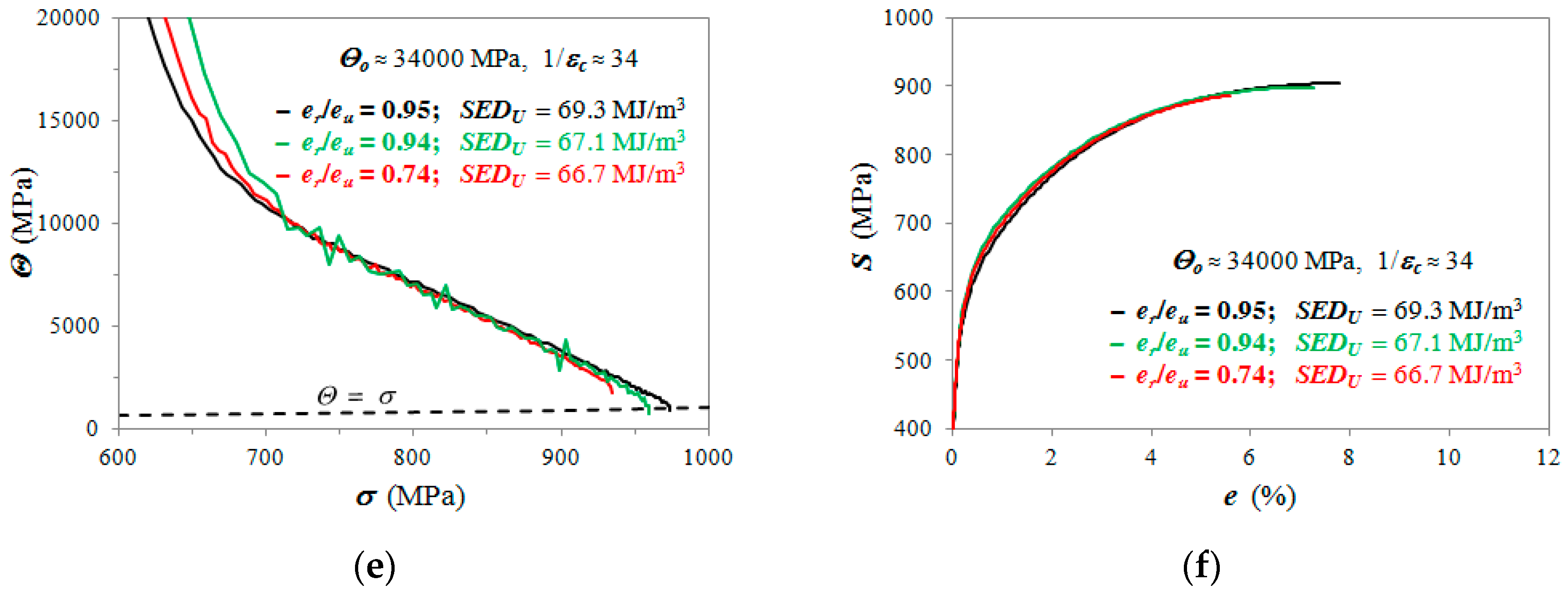
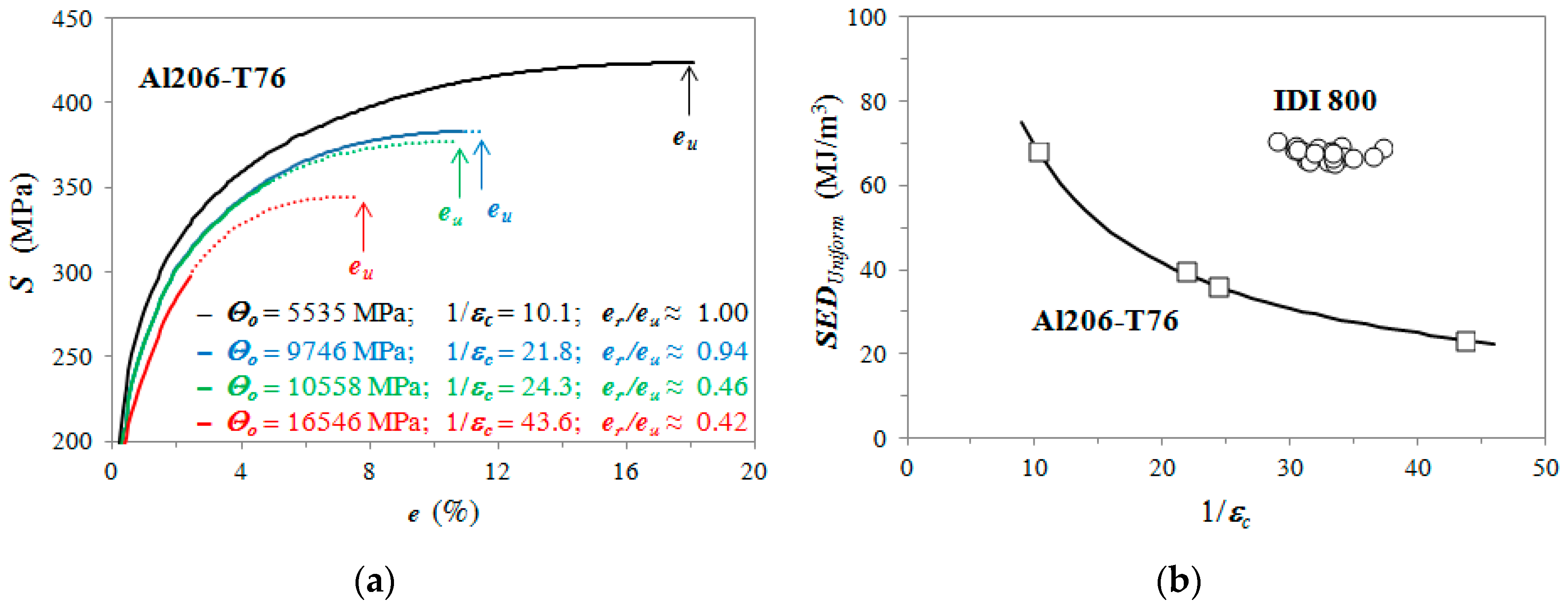
The fact that this assumption was fulfilled in IDI 800 is not obvious in metallic alloys produced through casting. For instance, in Al alloys castings for airspace applications this assumption has not been satisfied because of the nature and the high density of metallurgical defects [25]. As reported in Reference [26] for samples of Al206-T76 produced through the same casting route, the strain hardening behaviors of the flow curves (reported in Figure 8a of Reference [26]), with “different levels of quality index (as indicated by their elongations)” have significantly different Voce parameters 1/εc and Θo. The engineering flow curves corresponding to the strain hardening data shown in Figure 8a of Reference [26], are re-constructed and here reported in Figure 6a, where the dash parts of the engineering flow curves are beyond the rupture (er) until the achievement of the uniform elongations eu. In Figure 6a, the strain hardening behaviors of Al206-T76 casting samples [26] are strongly affected by metallurgical discontinuities and defects, since the Voce parameters change dramatically, and the engineering flow curves do not overlap at all. For instance, in the blue flow curve with Θo = 9,746 and 1/εc = 21.8, it was found er/eu ≈ 0.94, which could indicate a quite sound material with a SEDU of 39.8 MJ/m3. However, the black flow curve (er/eu ≈ 1.00) is significantly higher with significant larger SEDU of 68.1 MJ/m3. Indeed, the plastic behavior in the highly defected Al206-T76 changed so dramatically that the SEDU values of the re-constructed curves varied significantly from 68.1 (er/eu ≈ 1.00) to 23.2 MJ/m3 (er/eu ≈ 0.42), with a mean value of 41.8 MJ/m3 and a mean absolute variance of 13.2 MJ/m3. This data scatter was significantly wider than in IDI 800, where the mean absolute variance of SEDU values was 1.7 MJ/m3. Thus, from the er/eu values reported in Figure 6a, it was evident that these ratios could not be used as an indication of the microstructure quality of Al206-T76, because the strain hardening behavior was dramatically affected by metallurgical discontinuities and defects. Conversely, in the IDI 800 results reported in Figure 5, even the widest changes of er/eu did not produce any significant changes of SEDU. In Figure 6b, the SEDU values vs. 1/εc of IDI 800 and the Al206-T76 are reported for comparison.
From Figure 6b, other considerations arose. It was evident that the range of Voce parameters 1/εc in IDI 800 was very narrow if compared to Al206-T76. Even more significant, there was no large scatter in the SEDU values of IDI 800 that appeared constant if compared to Al206-T76, resulting in no evident relationship between SEDU and 1/εc. Indeed, SEDU and 1/εc are mathematically related through Equations (4) and (6), so this result meant that the differences of plastic behaviors were caused by random microstructure features that affected the tensile flow curves (σV and σo), or even by contributions that could be associated to measurement errors that were random by nature. This suggested that the nature and density of defects in the IDI 800 matrix was below a significant threshold and did not affect the flow curve shapes, but only affected the elongations to rupture that could be caused by single defects in the matrix according to the fracture mechanics approach. Conversely, in the specimens Al206-T76 the SEDU and 1/εc were strongly related, since the nature and density of defects in the samples were so high that the defects contributed significantly to the plastic behaviors of the different samples, affecting σV and σo. In the latter case, a direct comparison between er/eu should not make any sense. From Figure 6b the SEDU seemed to be a promising tool to discriminate between sound and defected castings, and potential applications could be carried out, for instance, on comparing DIs produced in thin walls and heavy sections (same chemical compositions with different production routes), or DIs produced with increasing alloying elements contents causing segregations and/or carbides precipitations (same production routes with different chemical compositions).
These results proved that, with IDI 800, the material quality assessment procedure [11,12] based on the matrix assessment and the integrity assessment diagrams are valuable. These results suggested that the procedure should be possible for any DI, where the difference of density between melt metal and floating scrap is so high that the concentration of metallurgical discontinuities and defects could be usually kept low with a proper foundry practice. However, even if the nominal compositions and pouring conditions of DIs are the same, from different foundries the density of defects may be significantly different, and so the fundamental assumption of the material quality assessment proposed here has to validated every time for every material. Thus, the capability of a foundry to adopt the procedure on a material could be itself an indication of the quality of the foundry practice.
5. Conclusions
A mathematical procedure to assess the microstructure quality of DIs [11,12] has been proposed and comes into two diagrams. A first matrix assessment diagram is for the classification of DIs ideal microstructure, that is, the matrix, identifying DIs with different silicon content and DIs produced through different routes and heat treatments. A second integrity assessment diagram is for the evaluation of the presence of potential metallurgical discontinuities and defects in DIs through comparing the rupture elongations (er) of DIs to the uniform elongations (eu) during tensile tests. Both diagrams are based on the formalism of the dislocation-density-related constitutive Voce equation that is related to dislocation dynamics. However, the procedure is based on the fundamental assumption that the strain hardening behaviors of DIs are not affected by the nature and the density of the metallurgical discontinuities and defects, and so they only affect the elongations to fracture. Strain Energy Density at the uniform strains (SEDU) calculations were used to have quantitative support to the strain hardening analysis.
- Twenty samples of IDIs 800 were intentionally selected in a untypical wide range of elongations to rupture to evaluate this assumption;
- The strain hardening behaviors and the SEDU values of the tested IDI 800 resulted in being independent of rupture conditions, and so the fundamental assumption was proven to be true;
- Interestingly SEDU analysis seemed to be a promising tool to discriminate between sound and defected castings, like, for instance, comparing DIs produced in thin walls and heavy sections, or DIs produced with increasing alloying elements contents causing segregations and carbides precipitations;
- The results proved that the microstructure quality assessment procedure was valid for IDI 800.
The procedure should also be valid in other DIs, even if indeed the fundamental assumption of the material quality assessment has to validated every time for every material, and for the same DI also for every foundry. Indeed, since metallurgical discontinuities and defects depend on the foundry practice, the capability of a foundry to adopt the proposed quality assessment procedure is itself an indication of the quality of the foundry practice.
Author Contributions
Material production, F.Z.; tensile testing, F.Z.; scanning electron microscopy G.A.; data formal analysis, G.A.; method conceptualization, G.A.; original draft preparation, G.A. and F.Z.; review and editing, G.A.
Acknowledgments
Davide Della Torre and Tullio Ranucci are warmly thanked for their experimental support.
Conflicts of Interest
The authors declare no conflict of interest.
References
- Menk, W. A new high strength high ductile nodular iron. Mater. Sci. Forum 2018, 925, 224–230. [Google Scholar] [CrossRef]
- Hammersberg, P.; Hamberg, K.; Borgström, H.; Lindkvist, J.; Björkegren, L. Variation of tensile properties of high silicon ductile irons. In Proceedings of the 11th International Symposium on the Science and Processing of Cast Iron, SPCI-XI 2017, Jonkoping, Sweden, 4–7 September 2017; Volume 925, pp. 280–287. [Google Scholar]
- González-Martínez, R.; de la Torre, U.; Lacaze, J.; Sertucha, J. Effects of high silicon contents on graphite morphology and room temperature mechanical properties of as-cast ferritic ductile cast irons. Part I—Microstructure. Mater. Sci. Eng. A 2018, 712, 794–802. [Google Scholar] [CrossRef]
- González-Martínez, R.; de la Torre, U.; Ebel, A.; Lacaze, J.; Sertucha, J. Effects of high silicon contents on graphite morphology and room temperature mechanical properties of as-cast ferritic ductile cast irons. Part II—Mechanical properties. Mater. Sci. Eng. A 2018, 712, 803–811. [Google Scholar] [CrossRef]
- Cekic, O.E.; Sidjanin, L.; Rajnovic, D.; Balos, S. Austempering kinetics of Cu-Ni alloyed austempered Ductile Iron. Met. Mater. Int. 2014, 20, 1131–1138. [Google Scholar] [CrossRef]
- Donnini, R.; Fabrizi, A.; Bonollo, F.; Zanardi, F.; Angella, G. Assessment of Microstructure Evolution of an Austempered Ductile Iron during Austempering Process through Strain Hardening Analysis. Met. Mater. Int. 2017, 23, 855–864. [Google Scholar] [CrossRef]
- Górny, M.; Angella, G.; Tyrala, E.; Kawalec, M.; Paz, S.; Kmita, A. Role of Austenitization Temperature on Structure Homogeneity and Transformation Kinetics in Austempered Ductile Iron. Met. Mater. Int. 2019, 25, 956–965. [Google Scholar] [CrossRef] [Green Version]
- Angella, G.; Zanardi, F.; Donnini, R. On the significance to use dislocation-density-related constitutive equations to correlate strain hardening with microstructure of metallic alloys: The case of conventional and austempered ductile irons. J. Alloy Compd. 2016, 669, 262–271. [Google Scholar] [CrossRef]
- Zanardi, F.; Bonollo, F.; Bonora, N.; Ruggiero, A.; Angella, G. A contribution to new material standards for Ductile Irons and Austempered Ductile Irons. Int. J. Met. 2017, 11, 136–147. [Google Scholar]
- Ductile Iron Data for Design Engineers/Section III Engineering Data/Part 1 Tensile Properties/Relationships between Tensile Properties. Available online: www.ductile.org (accessed on 14 June 2019).
- Donnini, R.; Zanardi, F.; Vettore, F.; Angella, G. Evaluation of microstructure quality in ductile irons based on tensile behaviour analysis. Mater. Sci. Forum 2018, 925, 342–349. [Google Scholar] [CrossRef]
- Angella, G.; Zanardi, F. Microstructure Quality Assessment of Isothermed Ductile Irons through Tensile Tests. In Proceedings of the 73rd World Foundry Congress “Creative Foundry”, WFC 2018–Proceedings, Krakow, Poland, 23–27 September 2018; pp. 265–266. [Google Scholar]
- Tiryakioğlu, M.; Campbell, J.; Staley, J.T. Evaluating Structural Integrity of Al-7%Si-Mg Alloys via Work Hardening Characteristics: I. Concept of Target Properties. Mater. Sci. Eng. A 2004, 368, 205–211. [Google Scholar] [CrossRef]
- Tiryakioğlu, M.; Staley, J.T.; Campbell, J. Evaluating Structural Integrity of Al-7%Si-Mg Alloys via Work Hardening Characteristics: II. A New Quality Index. Mater. Sci. Eng. A 2004, 368, 231–238. [Google Scholar] [CrossRef]
- Tiryakioğlu, M.; Alexopoulos, N.D.; Campbell, J. On the Ductility Potential of Cast Al-Cu-Mg (2009) Alloys. Mater. Sci. Eng. A 2004, 506, 23–26. [Google Scholar] [CrossRef]
- Tiryakioğlu, M.; Campbell, J. Quality index for aluminum alloy castings. Int. J. Met. 2014, 8, 39–42. [Google Scholar] [CrossRef]
- Zanardi Fonderie–Products: IDI. Patented by Zanardi Fonderie S.P.A., Italy. Available online: http://zanardifonderie.com/IDI (accessed on 14 June 2019).
- Estrin, Y. Dislocation theory based constitutive modelling: Foundations and applications. J. Mater. Process. Technol. 1998, 80, 33–39. [Google Scholar] [CrossRef]
- Angella, G.; Zanardi, F. Comparison among Different Constitutive Equations on Investigating Tensile Plastic Behavior and Microstructure in Austempered Ductile Iron. J. Cast. Mater. Eng. 2018, 2, 14–23. [Google Scholar] [CrossRef]
- Reed-Hill, R.E.; Crebb, W.R.; Monteiro, S.N. Concerning the analysis of tensile stress-strain data using log dσ/dεp versus log σ diagrams. Met. Trans. A 1973, 4, 2665–2667. [Google Scholar] [CrossRef]
- Angella, G.; Wynne, B.P.; Rainforth, W.M.; Beynon, J.H. Strength of AISI 316L in torsion at high temperature. Mater. Sci. Eng. A 2008, 475, 257–267. [Google Scholar] [CrossRef]
- Angella, G.; Donnini, R.; Ripamonti, D.; Maldini, M. Combination between Voce formalism and improved Kocks-Mecking approach to model small strains of flow curves at high temperatures. Mater. Sci. Eng. A 2014, 594, 381–388. [Google Scholar] [CrossRef]
- Serafini, A.; Angella, G.; Malara, C.; Brunella, M.F. Mechanical and Microstructural Characterization of AF955 (UNS N09955) Nickel-Based Superalloy after Different Heat Treatments. Mater. Sci. Eng. A 2018, 49, 5339–5352. [Google Scholar] [CrossRef]
- Caceres, C.H. A Rationale for the Quality Index of Al-Si-Mg Casting Alloys. Int. J. Cast. Met. Res. 1998, 10, 293–299. [Google Scholar] [CrossRef]
- Fiorese, E.; Bonollo, F.; Timelli, G.; Arnberg, L.; Gariboldi, E. New Classification of Defects and Imperfections for Aluminum Alloy Castings. Int. J. Met. 2015, 9, 55–66. [Google Scholar] [CrossRef]
- Tiryakioğlu, M.; Staley, J.T., Jr.; Campbell, J. The effect of structural integrity on the tensile deformation characteristics of A206-T71 alloy castings. Mater. Sci. Eng. A 2008, 487, 383–387. [Google Scholar] [CrossRef]
Figure 1.
Scanning electron microscopy (SEM) micrograph with secondary electron signal of typical spheroidal graphite perferritic microstructure of IDI 800 after metallographic polishing and etching with 2% Nital, consisting of nodular graphite (black) embedded in alternated ferrite (gray) and pearlite (bright).

Figure 2.
(a) Strain hardening analysis with typical IDI 800 (sample No. 18 in Table 1): differential data (dσ/dεp = Θ vs. σ) with the best fit of the differential form of Voce equation (Equation (3)) at high stresses; (b) experimental tensile flow curve with the best fitting Voce equation (Equation (2)).

Figure 3.
(a) Typical experimental tensile flow curve of IDI 800 (the same in Figure 2b) with the best fitting modified Voce equation (in Equation (7) n0 = 5.38, n1 = −543.9 and n2 = 0.96); (b) close-up at small strains to underline the excellent match between experimental flow curve and modified Voce equation.

Figure 4.
(a) Matrix assessment diagram for IDI 800 and GJS400; (b) integrity assessment diagram for IDI 800.
Figure 4.
(a) Matrix assessment diagram for IDI 800 and GJS400; (b) integrity assessment diagram for IDI 800.

Figure 5.
(a) Strain hardening data of typical IDI 800 with Θo ≈ 29,600 MPa and 1/εc ≈ 31; (b) engineering flow curves corresponding to the differential data in (a); (c) with Θo ≈ 31,600 MPa and 1/εc ≈ 33; (d) engineering flow curves corresponding to (c); (e) with Θo ≈ 34,000 MPa and 1/εc ≈ 34; (f) engineering flow curves corresponding to (e). The dot lines identified in (a)–(f) identify the Considère’s criterion Θ = σ.


Figure 6.
(a) Re-constructed engineering flow curves from the strain hardening data of Al206-T76 reported in Figure 8a in Reference [26]; the dashed parts of the flow curves concern the achievement of the uniform strains eu for the calculation of SEDU; (b) SEDU vs. 1/εc for IDI 800 and Al206-T76 from the flow curves in (a).


Table 1.
Summary of the Voce parameters for the quality assessment procedure of IDI 800 and strain energy density at uniform strains (SEDU).
Table 1.
Summary of the Voce parameters for the quality assessment procedure of IDI 800 and strain energy density at uniform strains (SEDU).
| No. | Mould | Θo (MPa) | 1/εc | εu,p | eu (%) | er/eu | SEDU (MJ/m3) |
|---|---|---|---|---|---|---|---|
| 1 | Y75 | 28,780.5 | 28.8 | 0.0822 | 8.95 | 1.17 | 70.4 |
| 2 | L25 | 28,892.7 | 31.4 | 0.0847 | 9.15 | 0.82 | 65.7 |
| 3 | Y25 | 29,386.7 | 31.1 | 0.0832 | 9.01 | 0.79 | 66.2 |
| 4 | Y25 | 29,648.3 | 30.9 | 0.0840 | 9.10 | 1.12 | 68.1 |
| 5 | Y25 | 29,758.1 | 31.2 | 0.0828 | 8.98 | 1.20 | 67.1 |
| 6 | Y50 | 30,224.5 | 30.1 | 0.0804 | 8.76 | 0.72 | 68.8 |
| 7 | Y50 | 30,340.6 | 30.3 | 0.0804 | 8.75 | 1.12 | 69.4 |
| 8 | L25 | 30,391.0 | 30.4 | 0.0807 | 8.79 | 1.09 | 68.8 |
| 9 | Y50 | 31,316.7 | 32.0 | 0.0828 | 8.97 | 0.97 | 68.9 |
| 10 | Y25 | 31,531.7 | 32.9 | 0.0801 | 8.68 | 0.91 | 65.6 |
| 11 | Y50 | 31,870.6 | 33.3 | 0.0803 | 8.69 | 0.72 | 65.3 |
| 12 | L25 | 32,115.0 | 31.8 | 0.0782 | 8.52 | 1.00 | 67.9 |
| 13 | Y50 | 32,338.6 | 33.3 | 0.0806 | 8.73 | 0.78 | 66.5 |
| 14 | Y50 | 32,539.3 | 33.0 | 0.0819 | 8.87 | 0.72 | 68.3 |
| 15 | L25 | 33,911.0 | 33.1 | 0.0766 | 8.34 | 0.96 | 67.9 |
| 16 | Y75 | 34,114.7 | 33.9 | 0.0783 | 8.50 | 0.94 | 67.1 |
| 17 | Y75 | 34,127.6 | 33.8 | 0.0804 | 8.72 | 0.95 | 69.3 |
| 18 | Y50 | 34,719.9 | 34.7 | 0.0776 | 8.42 | 0.74 | 66.7 |
| 19 | Y25 | 37,007.8 | 36.4 | 0.0778 | 8.42 | 0.78 | 66.9 |
| 20 | Y25 | 38,694.2 | 37.1 | 0.0764 | 8.28 | 1.12 | 69.0 |
© 2019 by the authors. Licensee MDPI, Basel, Switzerland. This article is an open access article distributed under the terms and conditions of the Creative Commons Attribution (CC BY) license (http://creativecommons.org/licenses/by/4.0/).
Share and Cite
MDPI and ACS Style
Angella, G.; Zanardi, F. Validation of a New Quality Assessment Procedure for Ductile Irons Production Based on Strain Hardening Analysis. Metals 2019, 9, 837. https://doi.org/10.3390/met9080837
AMA Style
Angella G, Zanardi F. Validation of a New Quality Assessment Procedure for Ductile Irons Production Based on Strain Hardening Analysis. Metals. 2019; 9(8):837. https://doi.org/10.3390/met9080837
Chicago/Turabian StyleAngella, Giuliano, and Franco Zanardi. 2019. "Validation of a New Quality Assessment Procedure for Ductile Irons Production Based on Strain Hardening Analysis" Metals 9, no. 8: 837. https://doi.org/10.3390/met9080837
Note that from the first issue of 2016, this journal uses article numbers instead of page numbers. See further details here.