Effect of Cryogenic Treatment on Microstructure and Wear Resistance of Carburized 20CrNi2MoV Steel

The State Key Laboratory of Rolling and Automation, Northeastern University, Shenyang 110819, China
*
Author to whom correspondence should be addressed.
Metals 2018, 8(10), 808; https://doi.org/10.3390/met8100808
Submission received: 13 September 2018
/
Revised: 3 October 2018
/
Accepted: 5 October 2018
/
Published: 9 October 2018
(This article belongs to the Special Issue Wear and Fracture of Steel Manufacturing Apparatus and Tools)
Abstract
:This paper investigated the response of carburized 20CrNi2MoV steel to cryogenic treatment including microstructure and wear resistance. Two cryogenic treatment methods including cryogenic treatment at −80 °C (CT) and deep cryogenic treatment at −196 °C (DCT) as well as conventional heat treatment (CHT) were carried out after carburizing process. Scanning electron microscopy (SEM), transmission electron microscopy (TEM) and X-ray diffractometry (XRD) were employed for microstructure characterization. The wear resistance was investigated by ball-on-disc sliding wear test on a multi-functional tribometer. The results show that the wear resistance of the experimental steel has been improved by 17% due to CT and by 25.5% due to DCT when compared to CHT. This significant improvement in wear resistance after cryogenic treatment is attributed to the microstructural changes including the finer martensitic structure, the reduction of retained austenite and the development of fine and more numerous carbides. Among these factors, the precipitation of fine carbides plays a more prominent role in enhancing wear resistance.
1. Introduction
Carburizing is a surface-hardening treatment which is usually used to improve the performance of components such as bearings and ring gears which require a very hard surface to resist wear along with a tough interior to resist impact in service [1,2,3,4]. The achievement after carburizing process is obtaining the carbon content gradient, i.e., carburized layer. However, the heat treatment following the carburizing process is the key to obtaining perfect microstructure and excellent performance. The conventional heat treatment (CHT) for carburizing steels is quenching and low temperature tempering. Whereas the major disadvantage of CHT is the terrible microstructure of coarse plate martensite with terribly high content of retained austenite (RA) [5,6,7]. The RA is a soft phase in microstructure and may have an adverse effect on properties like hardness and wear resistance [8,9]. In addition, RA is unstable and is easy to transform into martensite as a result of thermal and mechanical stresses encountered during service [10]. The transformation process is associated with volume expansion, therefore it leads to dimensional variation and distortion of the components and even to failure [11,12].
The CHT process results in a variety of problems of low hardness, poor wear resistance, dimensional instability and premature failure of components. The service life of components made of carburizing steels mainly depends on their wear resistance. Therefore, substantial efforts have been devoted to enhancing the service life of the carburizing steel components, especially by improving their wear resistance property. Cryogenic treatment is one of the effective approaches to obtaining better wear resistance of the carburizing steels [13,14,15]. There are two types of cryogenic treatment [16]: “cryogenic treatment” (CT) at temperature about −80 °C, and “deep cryogenic treatment” (DCT) at temperature about −196 °C. From the published works [17,18,19], it is widely accepted that CT is sufficient to transform RA into martensite which is considered to be a major factor for improving wear resistance. However, other recent studies have [20,21] indicated that wear resistance could be further improved by DCT. Since the content of RA was no longer changed with the temperature of cryogenic treatment decreasing, there must be other reasons responsible for the improvement of wear resistance. Recent studies have shown that [22,23] the improvement of wear resistance after DCT could be due to the following two aspects: (i) the reduction of the retained austenite content; (ii) the increase of carbides content. In addition to these, the residual stress existing in the carburized layer still has an effect on the wear resistance. The residual compressive stress exists in the case microstructures of carburized samples as a result of transformation and temperature gradients induced by quenching. The magnitude and distribution of the residual stress therefore are complex functions of the temperature gradients induced by quenching. The cryogenic treatment would also cause the residual stress changes and thus cause the changes of wear resistance. However, the residual stresses as a function of case depth are routinely measured by x-ray diffraction which would lead to a relatively high data error. Ghidelli et al. [24] put forward a new method of detecting residual stress by nanoindentation technique which is a very effective way to detect the residual stress of carburized layer. The effect of DCT on wear resistance varies with the steels, and there is not a satisfactory explanation for the phenomena up to now. The purpose of this paper is to investigate the effect of cryogenic treatment on the microstructure and wear resistance of the carburized 20CrNi2MoV steel. The wear resistance of the experimental steel after CT and DCT has been investigated by sliding wear test. In addition, in order to explain the changes of wear resistance, microstructure and worn surface observations were carried out.
2. Materials and Experimental Procedure
2.1. Material Preparation
The experimental steel was produced in a vacuum induction melting furnace (JZDL-ZG-0.1, Jinzhou, China). The ingot was forged into 150 × 80 × 50 mm3 billet. The chemical composition is listed in Table 1. For carburizing process, the samples were cut from the billet in size of 60 × 60 × 20 mm3 and were subjected to surface grinding process before carburizing process.
Carburizing process was performed in a continuous gas carburizing furnace (ZWZ, Wafangdian, China) which was composed of heating zone, carburizing zone, diffusion zone and equalization zone. The whole carburizing process would last for 27 h, consisting of 7 h in heating zone at 905 °C with 0.6% carbon potential, 6 h in carburizing zone at 935 °C with 1.3% carbon potential, 10 h in diffusion zone at 935 °C with 1.27% carbon potential, and 4 h in diffusion zone at 880 °C with 1.05% carbon potential. The process was designed to produce a case depth of ~2.0 mm. After carburizing, all samples were quenched immediately in oil.
2.2. Heat Treatment Process
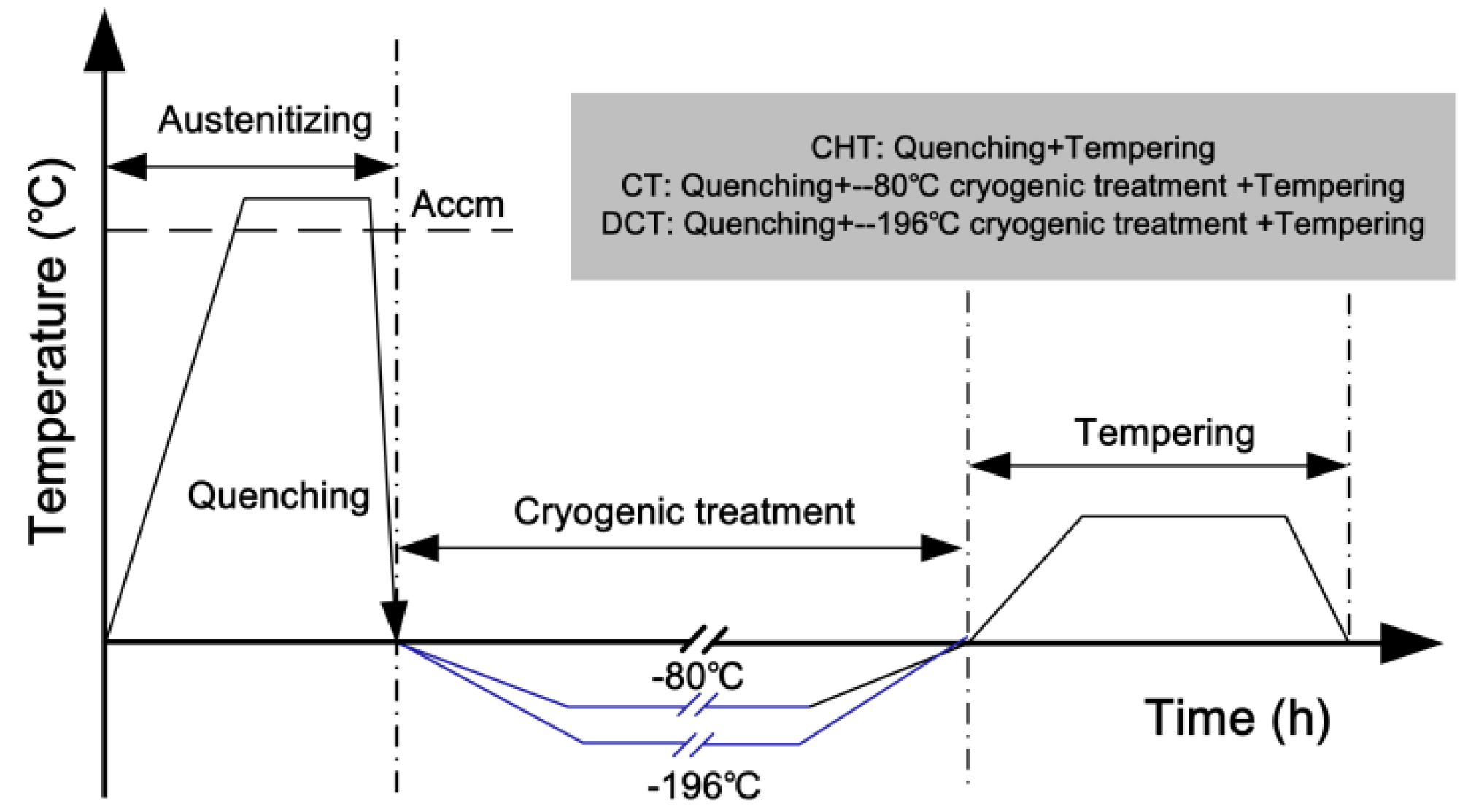
In this study, three types of heat treatment were carried out after carburizing process. All the samples of as-quenched condition after carburizing were re-austenitized at 880 °C for 45 min in a tube furnace under flowing argon atmosphere, quenched in oil and kept in oil for 30 s, and then air cooled to room temperature. Then, one sample as a reference, designated CHT, was directly heated to the tempering temperature 180 °C, held at the temperature for 2 h, and then air cooled to room temperature. Another sample, designated CT, was cooled from room temperature to −80 °C at a slow cooling rate of ~0.2 °C/s for avoiding thermal shocks, kept at the temperature for 4 h, gradually warming back to room temperature and thereafter heated to 180 °C for the same low-temperature tempering process as CHT sample. The DCT consisted of slowly cooling from the as-quenched condition to about −196 °C, holding at this temperature for 4 h and then gradually bringing the sample back to room temperature, and thereafter heated to 180 °C for the same low-temperature tempering process as CHT sample. The thermal cycles including quenching, cryogenic treatment and tempering are illustrated in Figure 1.
2.3. Sliding Wear Test and Hardness Test
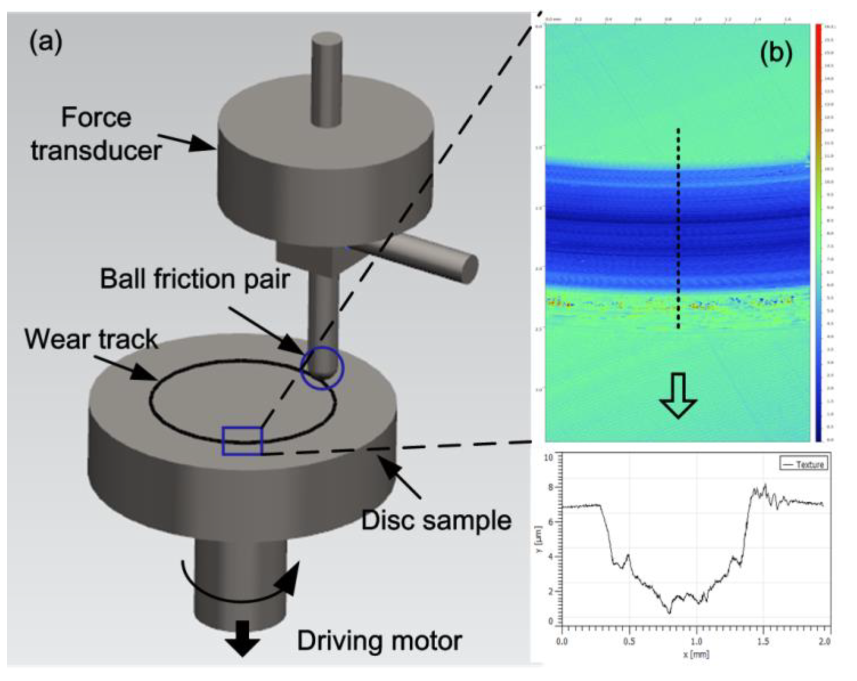
The sliding wear tests were performed at room temperature on a multi-functional tribometer from Rtec Instruments (Rtec-MFT 5000, San Jose, CA, USA). The schematic diagram of the experimental apparatus is shown in Figure 2a. The module of ball-on-disc configuration was applied for this test. The size of the disc-shaped samples was 40 mm in diameter and 10 mm in height. GCr15 balls with 5 mm in diameter and hardness of 63 HRC were used as friction pairs. During the sliding tests, the ball friction pairs were kept stationary while the discs were maintained as rotary. In this study, 20 N were selected as the loads to produce a contact pressure level of ~1.36 GPa. The sliding speed was set as 500 rpm and the sliding distance ranged from 100 to 1500 m. All the tests were repeated three times. After tests, the samples were carefully cleaned by alcohol in the ultrasonic cleaner and dried for the observation of worn surface morphology. The topography of worn surfaces were characterized by the 3D-profilometer attached to Rtec Instruments (Rtec instruments, San Jose, CA, USA), and the cross-sectional areas of the wear tracks were calculated at the same time, as shown in Figure 2b. The microhardness was tested by FUTURE-TECH FM-700 Vickers durometer (FUTURE-Tech, Kawasaki, Japan) with applied load of 1kgf. All the hardness values presented in this study were an average of three repeated tests.
2.4. Microstructural Characterization
The carbon content distribution of carburized case was analyzed by a Shimadzu PDA-5500 II direct reading spectrograph (Shimadzu, Kyoto, Japan). Microstructures were observed by a ZEISS ULTRA-55 scanning electron microscopy (ZEISS-SEM, Jena, Germany) after manual grinding, mechanical polishing, and etched by 4% nital solution. A FEI Tecnai G2 F20 transmission electron microscopy (FEI-TEM, Hillsborough, OR, USA) was used to observe the fine structure at an accelerated voltage of 200 kV. To prepare the thin foils for TEM, firstly, slices of 500 μm thick were cut from samples by wire cutting, then thinned to 40 μm by manual grinding, and punched into standard TEM discs of 3 mm in diameter. Finally, the foils were electropolished by the solution of 8% perchloric acid and 92% alcohol at a potential of 32 V and temperature of −20 °C. A D/max2400 X-ray diffractometry (XRD) with Cu Kα radiation (Shimadzu, Kyoto, Japan) was employed to identify the retained austenite content in the microstructure. The diffraction angle ranged from 30 to 120°, with a 0.05° step at a speed of 1°/min. The worn surfaces of the samples were also studied by SEM.
3. Results
3.1. Carbon Content Gradient and Hardness Gradient
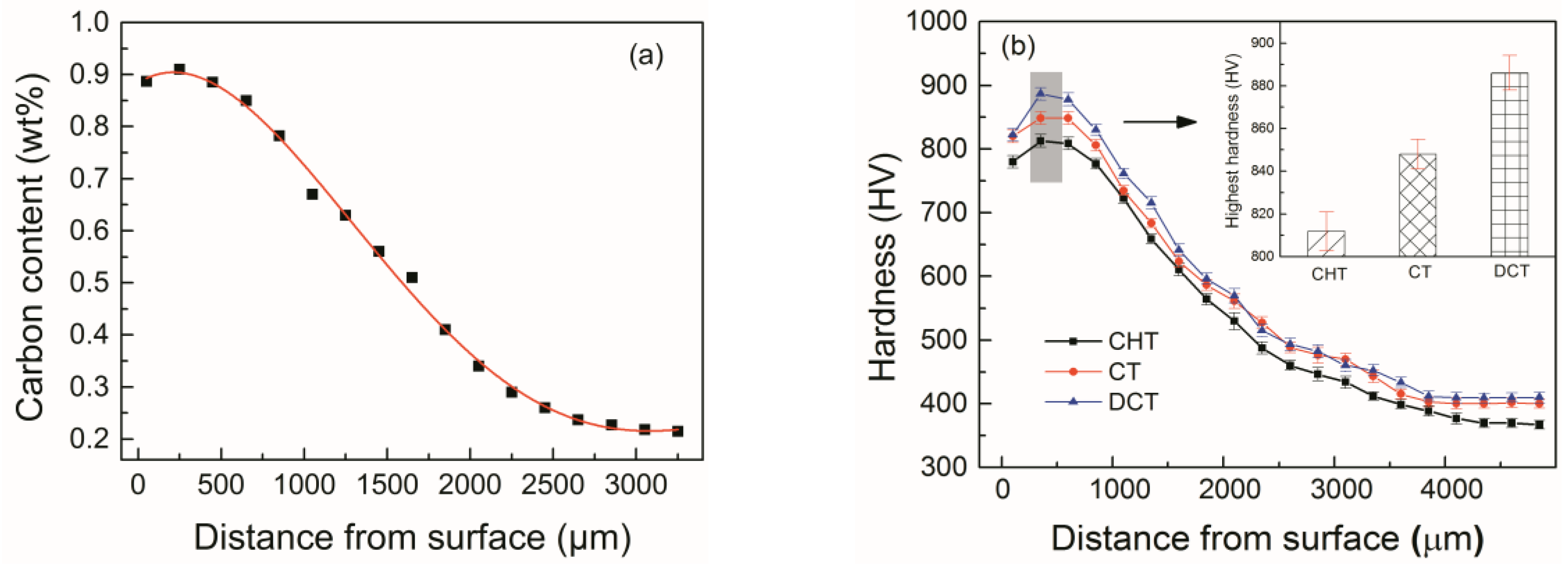
The carbon content gradient of samples after carburizing as a function of distance from surface is shown in Figure 3a. The carbon content of the surface layer is ~0.88 wt.%, and at the case depth is ~200 μm from the surface, the highest the carbon content reaches is ~0.9 wt.%. The total case depth is ~2.3 mm and the carbon content gradient curve falls flat.
The hardness gradients of the samples after different heat treatments are shown in Figure 3b. It is shown that the hardness values decrease continuously with the increase of depth from case to center of all the specimens. The variation trend of hardness is in keeping with that of the carbon content. As demonstrated in Figure 3b, cryogenic treatment markedly increases the hardness of the carburized layer. The maximum hardness value of CHT sample is 812 HV while that of CT sample has reached to 848 HV. The DCT further improved hardness as compared to CT and the hardness value reached the maximum of 886 HV. The increase of hardness by cryogenic treatment could improve the wear resistance to some extent.
3.2. Wear Resistance
The wear performances of samples suffered from CHT, CT and DCT were compared by the measurement of wear volume and wear rate. Wear rate was expressed as the wear volume loss per unit sliding distance:
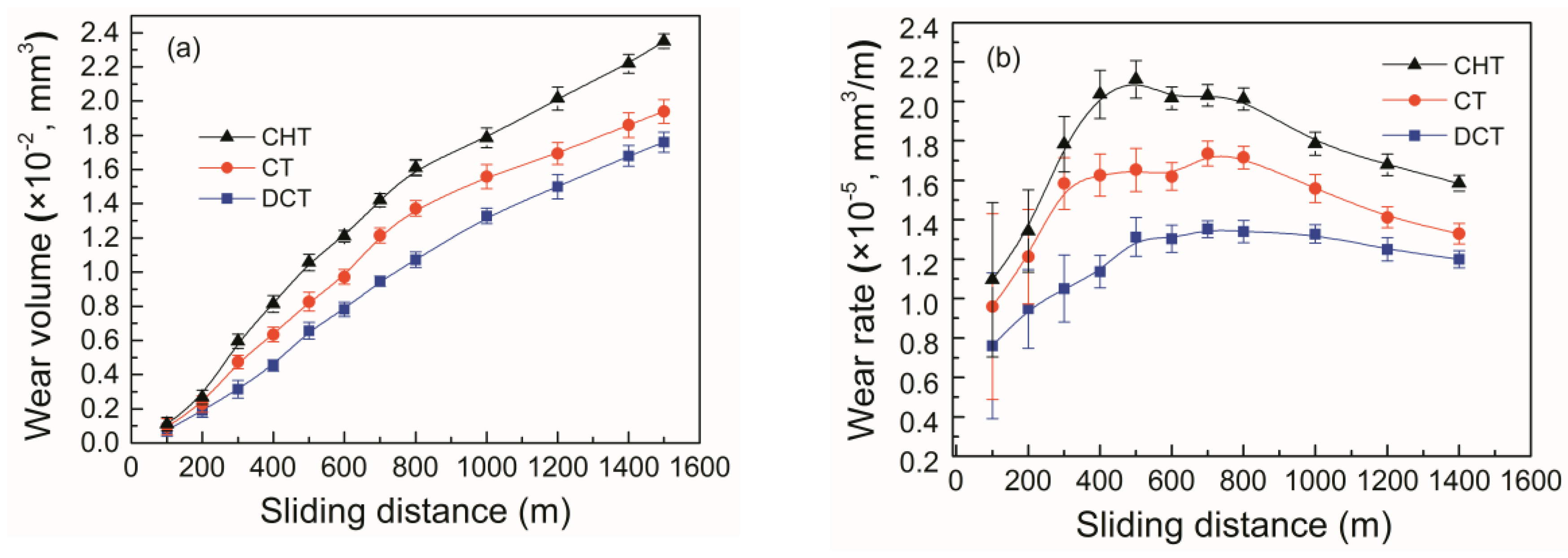
where, Wr was the wear rate (mm3/m), L was the sliding distance (m), and WV was the wear volume (mm3) which was calculated by the product of the cross-sectional area of wear track and its circumference. Figure 4a shows the variation of wear volume with sliding distance of samples under different heat treatments. It is observed that the wear volume of all the specimens increases rapidly with the increase of sliding distance. The wear volume of CT as well as DCT samples is less than that of CHT samples at the same sliding distance, and the wear volume of DCT samples is the least. Figure 4b illustrates the wear rate of the CHT, CT and DCT samples. The wear rates of all the samples present the trend of firstly increasing and then slightly decreasing along with sliding distance increasing. At the initial stage of sliding distance less than 400–500 m, the wear of samples was severe and resulted in a rapid rise of wear rate. This process is the breaking-in wear stage. With the prolongation of sliding distance, the wear rate started to decline and the specimens entered the stable wear stage. The wear rate at the same sliding distance of the samples that suffered from cryogenic treatment is much lower than that of CHT samples. Furthermore, the wear rate of DCT samples is significantly lower than that of CT samples.
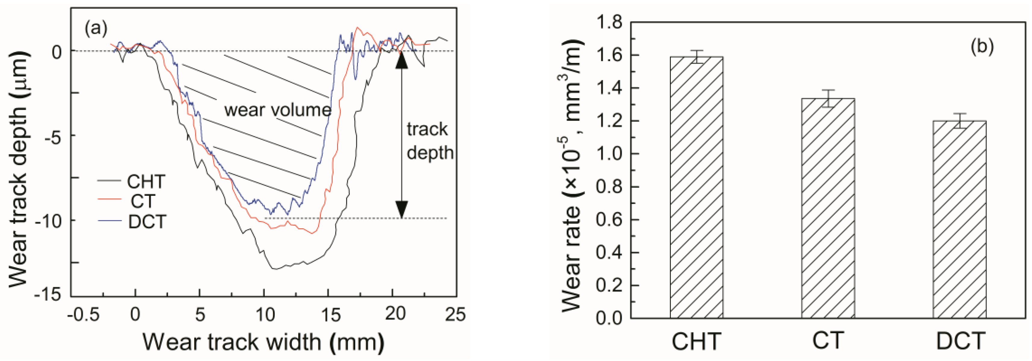
The performance of wear resistance can be seen more intuitive according to the wear depth and wear area obtained from the profile of the wear track. Figure 5a shows the profile of the wear track of samples under different heat treatment after sliding for 1500 m. The track depths of CHT, CT and DCT samples are 13 μm, 11 μm and 9.8 μm, respectively. Meanwhile, the track width of the samples suffered from cryogenic treatment becomes narrow compared to that of the CHT samples. The wear volumes of CHT, CT and DCT samples, are 2.37 × 10⁻² mm3, 1.96 × 10⁻² mm3 and 1.76 × 10⁻² mm3, respectively, while the corresponding wear rates are 1.57 × 10⁻⁵ mm3/m, 1.3 × 10⁻⁵ mm3/m and 1.17 × 10⁻⁵ mm3/m, respectively, as shown in Figure 5b. The wear rate has been considerably improved by 17% due to CT and by 25.5% due to DCT when compared to CHT.
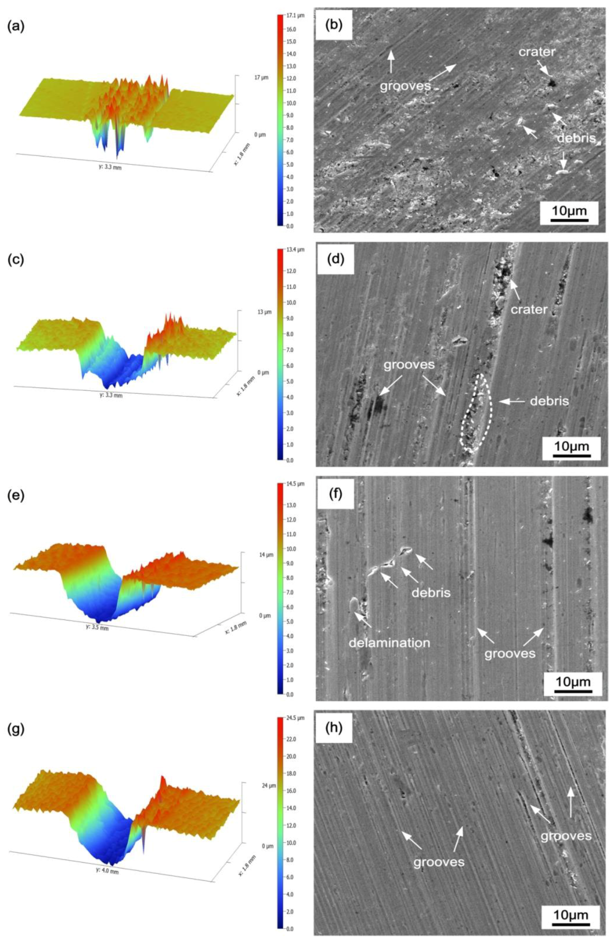
To understand the wear mechanism of the steels under sliding wear, the topography of worn surfaces of samples were investigated. Firstly, Figure 6 shows the wear tracks features at different wear stages of DCT sample. As shown in Figure 6a, for a sliding distance of 100 m, many raised burrs (spalls) and shallow grooves are observed corresponding to the two-dimensional morphology being featured of shallow grooves and large craters around with scattered debris, as shown in Figure 6b. With increasing the sliding distance to 500 m, the three-dimensional morphology of the worn surface reveals different depths of grooves, as shown in Figure 6c. The two-dimensional morphology is characterized by wide grooves of different depths and a small number of debris, as shown in Figure 6d. When the sliding distance increases to 1000 m, the three-dimensional morphology of the wear scar is a deep groove (Figure 6e). While for the two-dimensional morphology of the surface, as shown in Figure 6f, deep grooves and delaminations wear become dominant, but a certain amount of large craters exist in some regions. When sliding wear is increased to 1500 m, the wear surface still has the characteristic of groove wear, but the groove becomes narrow and the wear track becomes deep, as shown in Figure 6g,h. Therefore, from the observation of the wear surfaces at different wear stages, it can be seen that groove wear took the predominant position during sliding wear process, and the groove wear gradually narrows down with the prolongation of wear duration.
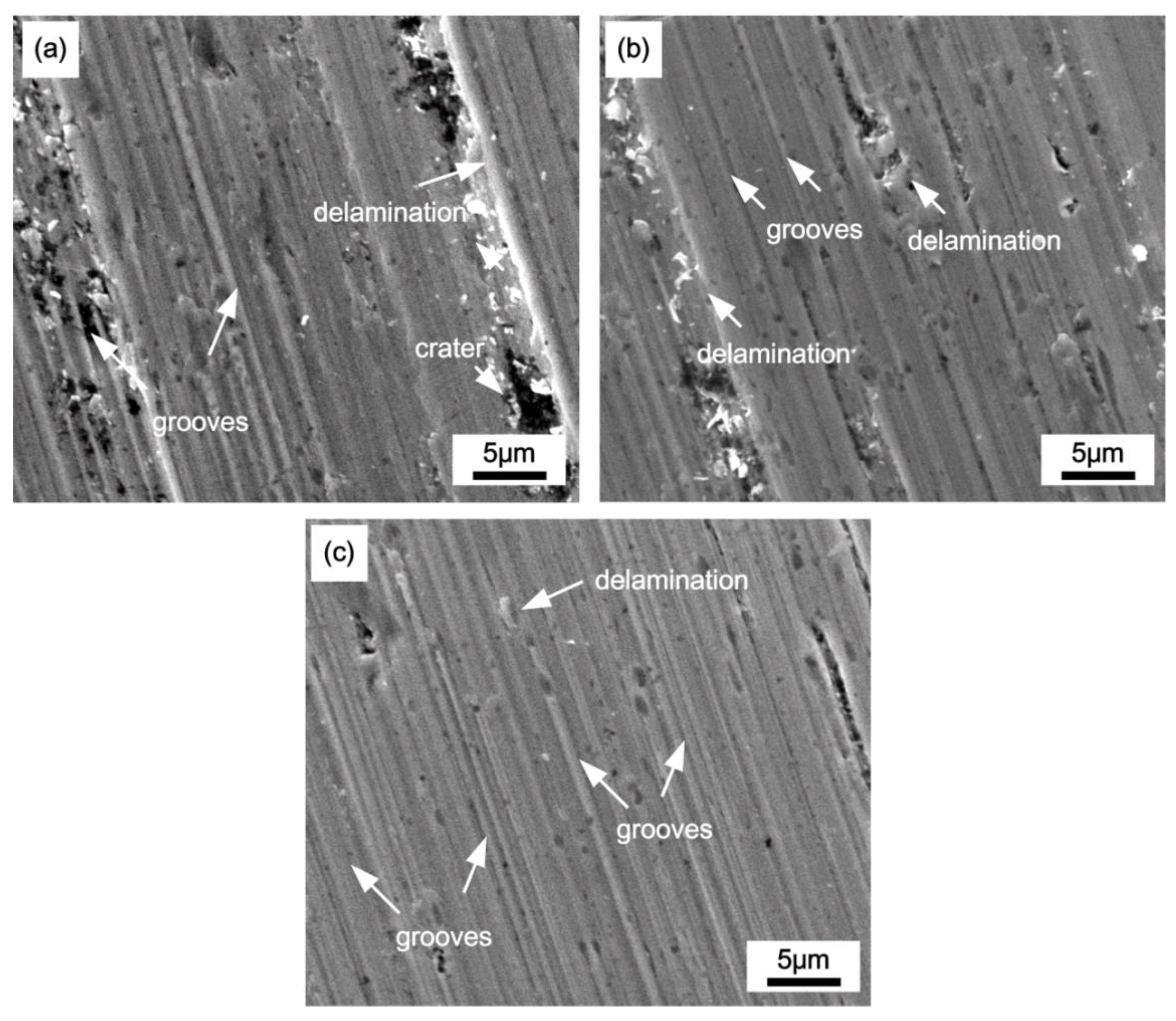
The variation of wear rate of the samples under different heat treatment is probably related to the different wear mode. Figure 7 represents the SEM morphologies of the worn surfaces of CHT, CT and DCT samples after sliding 1500 m. Deep parallel grooves as well as delaminations scattered around the grooves are the main morphologies of the worn surface for all the samples under identical wear conditions. The wear surface of CHT sample (Figure 7a) exhibits very deep and wide grooves parallel to the sliding direction and large amount of delaminations and craters, while the worn surfaces of CT (Figure 7b) and DCT (Figure 7c) appear much smoother. When comparing the feature of the worn surfaces of CT and DCT, it can be found that the groove is narrower and shallower for DCT samples. This indicates that the plastic deformation degree of CT sample is severe when comparing to DCT sample.
3.3. Microstructure
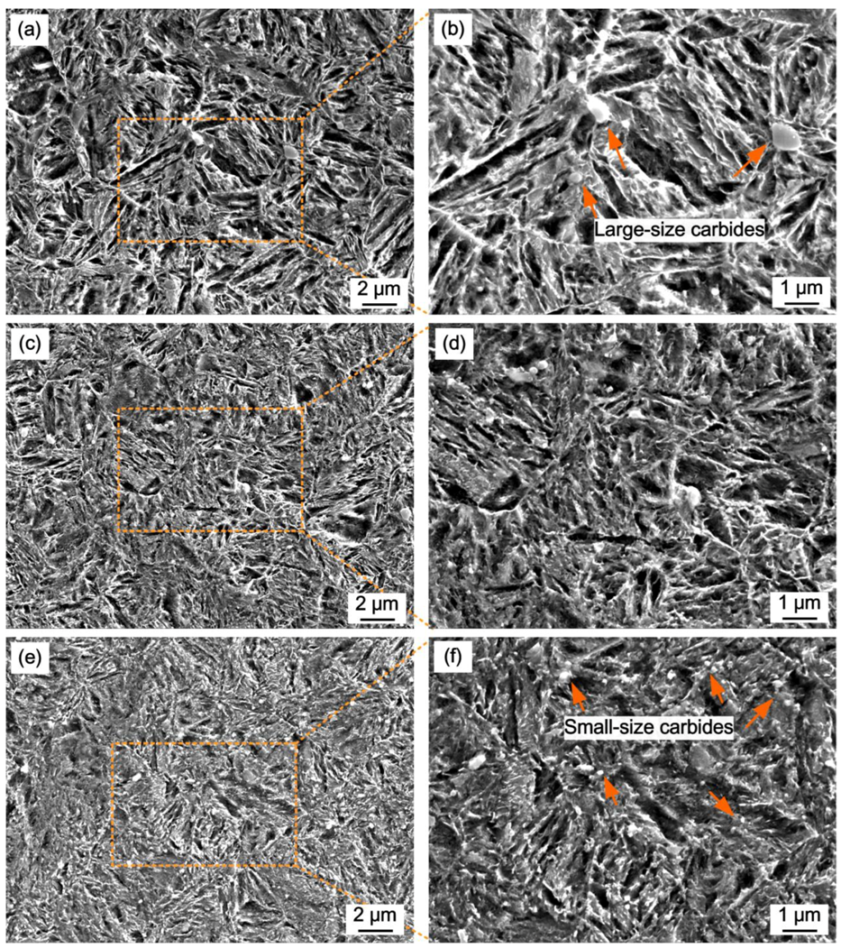
The effect of cryogenic treatment on wear resistance is definitely attributed to the microstructure of the experimental steel. Therefore, microstructural examination was carried out to reveal the changes in microstructure on account of cryogenic treatment. Firstly, the SEM micrographs of CHT, CT and DCT specimens are shown in Figure 8. It is observed that the microstructures of CHT, CT and DCT specimens are all mainly composed of plate martensite with a large number of carbides in the matrix, but there are also obvious differences. The first significant change is that the microstructure becomes finer after cryogenic treatment as compared to CHT sample. Furthermore, as the cryogenic treatment temperature decreases, the microstructure becomes refined. It can be contributed to crystal breaking caused by the plastic deformation resulting from the martensite transformation at low temperature [25]. The other significant change is the distribution and volume fraction of carbides in the matrix. As shown in Figure 8b, the carbides in CHT sample are mainly 200–300 μm in size and the distribution is inhomogeneous, while the small-size carbides are hardly observed. In CT sample of Figure 8d, the large-size carbides are disappeared and replaced with a certain amount of small-size particles. When comparing Figure 8d,f, the carbides in the DCT sample become more refined and more homogeneous. Meanwhile, the volume fraction of precipitated carbides markedly increases after cryogenic treatment.
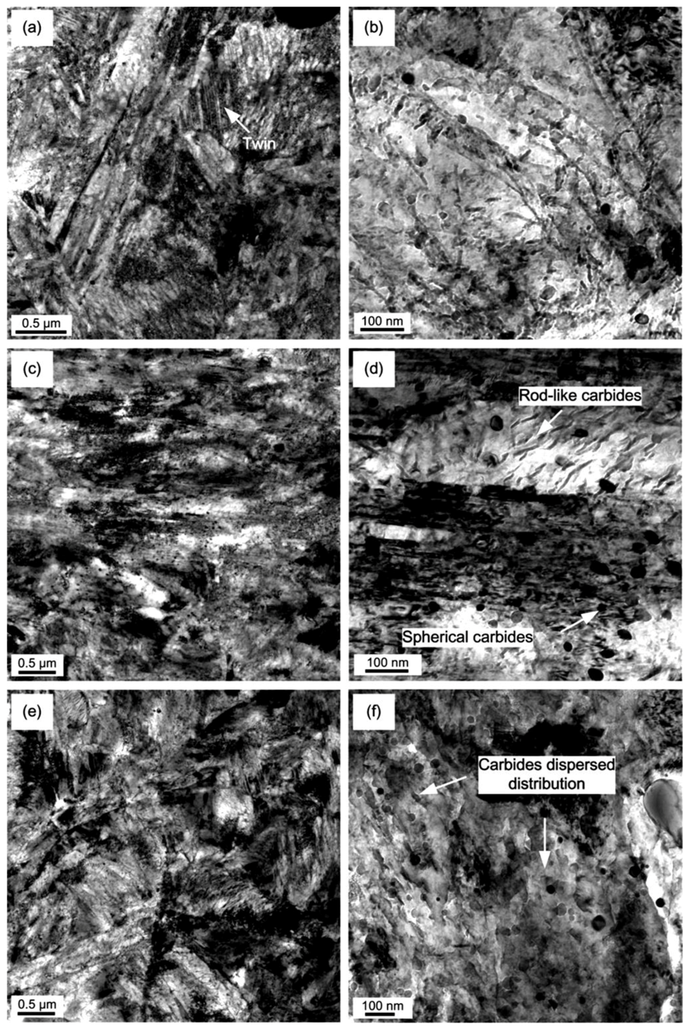
In order to further investigate the fine microstructure, especially the carbide precipitation, the microstructures of CHT, CT and DCT samples are observed by TEM, and as illustrated in Figure 9. The morphology of martensite is of plate martensite in all the samples. In CHT samples, the coarse twinned substructure can be clearly observed, as demonstrated in Figure 9a, which is no longer observed in CT and DCT samples. The CHT samples exhibit a greater number of large-size carbides but a smaller number of small-size carbides. For the CT sample, the number of large-size carbides is significantly decreased while small-size carbides in the microstructures are observed to be fine and uniformly distributed. As shown in Figure 9d, some rod-like carbides appear in some areas, and some fine spheroidally carbides appear in other areas which have a considerable dislocation density. While comparing the microstructure of DCT with CT, as shown in Figure 9f, precipitation of carbides in DCT samples are further increased with small spherical carbide particles in size between 10 and 40 nm in diameter being distributed more numerously and uniformly in the matrix. Using image analysis, the volume fraction of carbides in different samples was counted and calculated. The results show that the volume fraction of carbides in CHT, CT and DCT samples is 9.8%, 13.6% and 18.7%, respectively. The volume fraction of the samples that suffered from cryogenic treatment is higher than that in the CHT ones. Furthermore, with the temperature of cryogenic treatment decreasing, the volume fraction of carbides further increases.
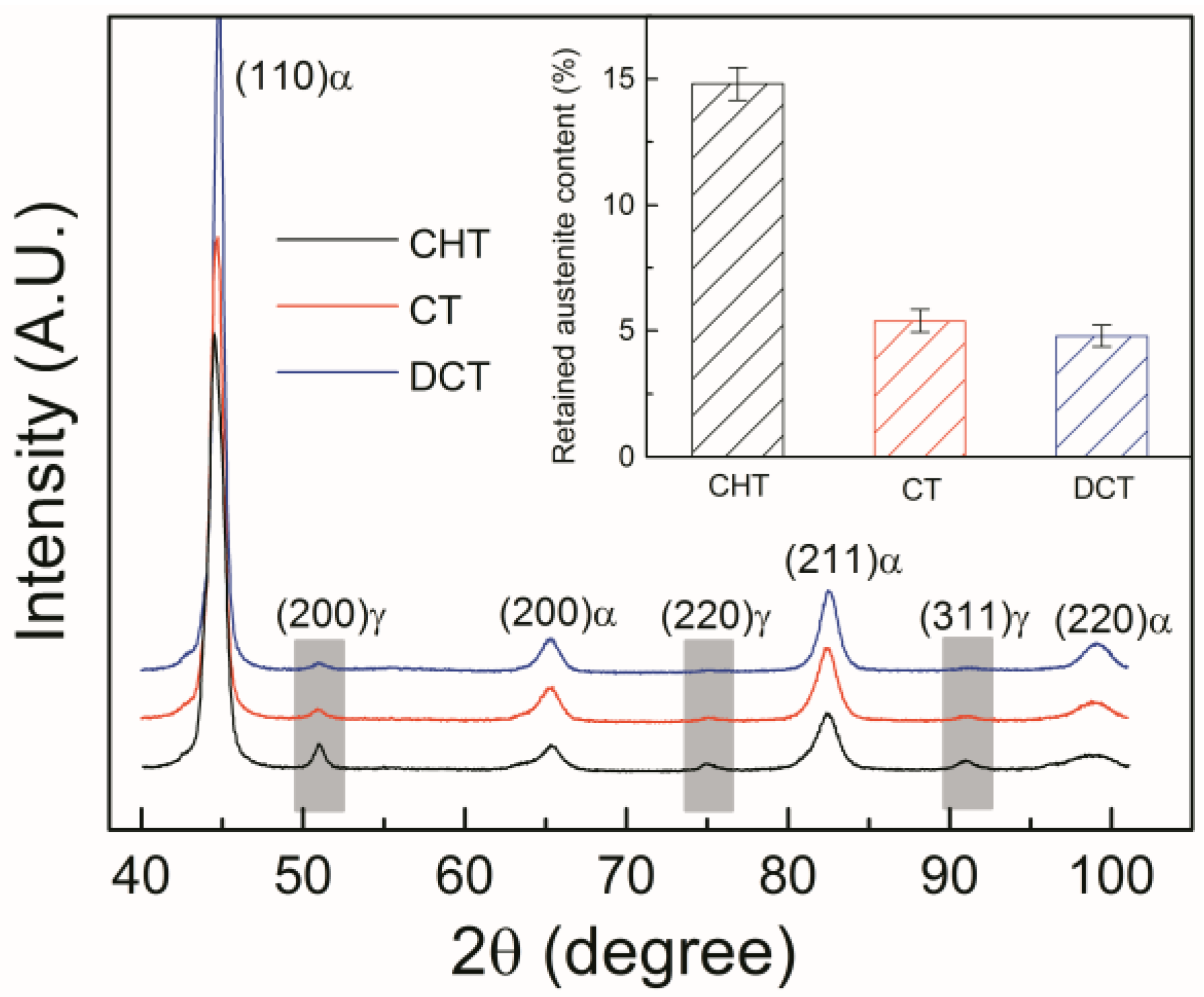
The other obvious characteristic after cryogenic treatment is the retained austenite transformation. The XRD patterns of the samples are illustrated in Figure 10. It can be seen that the peaks of austenite exhibit a low intensity value after cryogenic treatment, which indicates that a fraction of retained austenite transforms into martensite during the cryogenic treatment process, as highlighted in Figure 10.
The relative proportions of austenite and martensite were calculated from the X-ray diffractograms by using the formula:
where and are the integrated intensities of the austenite and martensite peaks, respectively, and and are the relative intensity factors of the corresponding crystallographic planes. For simplicity, the lower angle peaks γ(111) and M/α(110) were neglected and only the peak M/α(200), M/α(211), γ(220) and γ(311) were used for these calculations. The corresponding relative intensity factors were adopted from those calculated by Dickson [26] for Fe-1%C alloys. The phase fraction of each sample was calculated and is shown in Table 2. As can be seen, the volume fraction of austenite is decreased sharply from 11.8% to 5.6% when compared with CHT and CT samples, while the volume fraction of austenite decreased rarely from 5.6% to 4.8% when compared with CT and DCT samples. It can be concluded that the retained austenite cannot transform into martensite completely even when cryogenic treatment or deep cryogenic treatment was carried out, corresponding to the existence of austenite peaks of the CT and DCT samples as shown in Figure 10.
4. Discussion
The results on microstructure evolution, wear test and worn surface morphology reveal that the wear resistance mainly depends on the microstructure. In the discussion, two major questions are discussed. Firstly, the microstructure evolution is analyzed. Secondly, the relationship between microstructure and wear resistance is discussed.
4.1. Microstructure Evolution during Cryogenic Treatment
As stated above, the significant microstructure changes as a result of cryogenic treatment can be summed up as follows: firstly, the microstructure becomes more refined and dense; secondly, the volume fraction of retained austenite is decreased; thirdly, the precipitation of fine carbides is increased.
As is known, the characteristic of high carbon content in the carburized layer of the experimental steel would lower the characteristic temperatures of Ms and Mf. The temperature of Mf is far below the room temperature for the carburized layer. Therefore, the conventional heat treatment fails to transform a considerable amount of austenite into martensite and therefore leads to an unacceptable content of retained austenite for about 11.8%. As the temperature continuously decreases to below room temperature during cryogenic treatment, the transformation of retained austenite to martensite continues to take place. Because the specific volume of martensite is greater than that of austenite, martensitic transformation results in an increase in volume and is accompanied by the introduction of compressive stress in the retained austenite. As the sample is held at cryogenic temperature for a long enough time, the retained austenite gradually transforms into martensite. However, when a low amount of retained austenite remains in microstructure, the retained austenite would be surrounded by martensite. The martensite shrinks at cryogenic temperature and imposes an additional compression on the retained austenite. The compressive state of stress is expected to stabilize austenite and the retained austenite is difficult to further transform [27]. Therefore, while both CT and DCT reduce the volume fraction of retained austenite drastically, there is still a small amount of retained austenite. The volume fractions of retained austenite of CT and DCT samples are 5.3% and 4.6%, respectively.
The mechanism of the precipitation of fine carbides by cryogenic treatment is explained as follows. Because of the volume contraction at cryogenic temperature, crystal lattice decreases and internal micro stresses are generated. These internal stresses are responsible for the formation of crystal defects and lead to an increase of dislocation density [25,28]. The carbon atoms would disable diffuse at cryogenic temperature, but they could be captured by the gliding dislocations and segregate nearby by dislocations [29]. Carbides cannot precipitate at cryogenic temperature; however, the segregated carbon and alloying atoms can form clusters that ultimately become the nuclei for the development of carbides during successive tempering [30]. Because the segregation carbon atoms clusters are random and homogeneous, the precipitated carbides are numerous and dispersed. In the CT process, the cryogenic temperature is not sufficient to make martensitic lattice shrinkage and therefore has less influence on the carbides’ precipitation. Therefore, the volume fraction of the precipitated carbides in the CT sample is less than that in the DCT sample [20].
4.2. Relationship between Wear Resistance and Microstructure
The results of wear tests indicate that the wear resistance has been significantly improved due to cryogenic treatments. The wear rate of the specimen that suffered from CT treatment, compared to the specimen of CHT treatment, decreases by ~17%, in the same case of sliding 1500 m. From the conventional perspective, there is agreement that the major factor for improving wear resistance by cryogenic treatment is the decrease of the content of retained austenite and the increase of hardness. The XRD and hardness results have supported this perspective with the volume fraction of retained austenite decreasing sharply from 11.8% to 5.6% when compared with CHT and CT samples, along with the hardness of CT specimen markedly increasing from 812 to 848 HV as compared to the CHT sample. Therefore, the wear resistance is greatly improved after the CT process.
Furthermore, the wear rate of the DCT sample is significantly lower than that of the CT sample; that is, the improvement of wear resistance after the DCT process is considerably higher than that suffered from the CT process. However, both CT and DCT almost reduce retained austenite completely and the volume fractions of retained austenite of CT and DCT samples are only 5.3% and 4.6%, respectively. Thus, there must be some other phenomena than the variation in retained austenite content responsible for the difference in their wear resistance. Based on the experimental measurement of the precipitation of carbides from SEM and TEM, the volume fraction of carbides in the CHT, CT and DCT samples is 9.8%, 13.6% and 18.7%, respectively. The volume fraction of carbides in the DCT sample is higher than in the CT sample. The increase in carbides’ precipitation also brings the increase of hardness from 848 to 886 HV. Therefore, it is concluded that the improvement in wear resistance by DCT over CT could be due to the greater precipitation of fine carbides. The substantial precipitation of carbides in DCT samples can reduce the carbon and alloy contents in the matrix and therefore improves the toughness of the matrix. Therefore, the microstructure composed of more carbides and tougher matrix is certain to lead to the improvement of wear resistance.
On the basis of the XRD analysis, it can be concluded that the retained austenite cannot transform into martensite completely even when deep cryogenic treatment is carried out. According to the SEM observation (Figure 7) of the worn surface, the predominant wear mechanisms of samples were groove and delamination. The wear rate may be controlled by crack nucleation and propagation beneath the surface. Retained austenite may inhibit crack propagation either by changing the crack propagation direction or by absorbing energy. Therefore, a small amount of retained austenite in the microstructure is partly beneficial to the improvement of wear resistance.
5. Conclusions
In this paper, the effect of cryogenic treatment on the microstructure and wear resistance of carburized 20CrNi2MoV steel was investigated. The microstructure evolution during cryogenic treatment and the relationship between wear resistance and microstructure were analyzed. The conclusions of the investigation are as follows:
- (1)
- The significant microstructure changes as a result of cryogenic treatment are summed up as follows: the microstructure becomes more refined and dense; the volume fraction of retained austenite is decreased and the precipitation of fine carbides is increased.
- (2)
- The wear resistance is improved by 17% due to CT and by 25.5% due to DCT when compared to CHT. The significant improvement in wear resistance after cryogenic treatment is attributed to the microstructural changes. The precipitation of fine carbides plays a more prominent role in enhancing wear resistance.
Author Contributions
Both authors contributed equally to the work.
Funding
This research was funded by National High-tech R&D Program (863 Program), grant number 2012AA03A503.
Acknowledgments
The authors are grateful to the State Key Laboratory of Rolling and Automation for material preparation and mechanical properties testing.
Conflicts of Interest
The authors declare no conflict of interest.
References
- Yang, Z.N.; Ji, Y.L.; Zhang, F.C.; Zhang, M.; Nawaz, B.; Zheng, C.L. Microstructural evolution and performance change of a carburized nanostructured bainitic bearing steel during rolling contact fatigue process. Mater. Sci. Eng. A 2018, 725, 98–107. [Google Scholar] [CrossRef]
- Li, B.; Li, C.; Li, Z.; Dong, J. Microstructure and mechanical properties of Fe-Cr-2Ni-Mo-V steel in carburizing process. Procedia Manuf. 2018, 15, 1612–1618. [Google Scholar] [CrossRef]
- Paulson, N.R.; Golmohammadi, Z.; Walvekar, A.A.; Sadeghi, F.; Mistry, K. Rolling contact fatigue in refurbished case carburized bearings. Tribol. Int. 2017, 115, 348–364. [Google Scholar] [CrossRef]
- Wang, Y.; Yang, Z.; Zhang, F.; Wu, D. Microstructures and mechanical properties of surface and center of carburizing 23Cr2Ni2Si1Mo steel subjected to low-temperature austempering. Mater. Sci. Eng. A 2016, 670, 166–177. [Google Scholar] [CrossRef]
- Amini, K.; Akhbarizadeh, A.; Javadpour, S. Cryogenic heat treatment of the ferrous materials–a review of the current state. Metall. Res. Technol. 2016, 113, 611. [Google Scholar] [CrossRef]
- Çiçek, A.; Kara, F.; Kıvak, T.; Ekici, E.; Uygur, I. Effects of deep cryogenic treatment on the wear resistance and mechanical properties of AISI H13 hot-work tool steel. J. Mater. Eng. Perform. 2015, 24, 4431–4439. [Google Scholar] [CrossRef]
- Shen, Y.; Moghadam, S.M.; Sadeghi, F.; Paulson, K.; Trice, R.W. Effect of retained austenite–compressive residual stresses on rolling contact fatigue life of carburized AISI 8620 steel. Int. J. Fatigue 2015, 75, 135–144. [Google Scholar] [CrossRef]
- Roy, S.; Sundararajan, S. The effect of heat treatment routes on the retained austenite and Tribomechanical properties of carburized AISI 8620 steel. Surf. Coat. Technol. 2016, 308, 236–243. [Google Scholar] [CrossRef]
- Paladugu, M.; Hyde, R.S. Influence of microstructure on retained austenite and residual stress changes under rolling contact fatigue in mixed lubrication conditions. Wear 2018, 406, 84–91. [Google Scholar] [CrossRef]
- Kim, H.; Lee, J.; Barlat, F.; Kim, D.; Lee, M.G. Experiment and modeling to investigate the effect of stress state, strain and temperature on martensitic phase transformation in TRIP-assisted steel. Acta Mater. 2015, 97, 435–444. [Google Scholar] [CrossRef]
- Cui, W.; San-Martín, D.; Rivera-Díaz-del-Castillo, P.E. Stability of retained austenite in martensitic high carbon steels. Part I: Thermal stability. Mater. Sci. Eng. A 2018, 711, 683–695. [Google Scholar] [CrossRef]
- Tewary, U.; Mohapatra, G.; Sahay, S.S. Distortion Mechanisms During Carburizing and Quenching in a Transmission Shaft. J. Mater. Eng. Perform. 2017, 26, 4890–4901. [Google Scholar] [CrossRef]
- Preciado, M.; Bravo, P.M.; Alegre, J.M. Effect of low temperature tempering prior cryogenic treatment on carburized steels. J. Mater. Process Technol. 2006, 176, 41–44. [Google Scholar] [CrossRef]
- Bensely, A.; Prabhakaran, A.; Lal, D.M.; Nagarajan, G. Enhancing the wear resistance of case carburized steel (En 353) by cryogenic treatment. Cryogenics 2005, 45, 747–754. [Google Scholar] [CrossRef]
- Baldissera, P.; Delprete, C. Effects of deep cryogenic treatment on static mechanical properties of 18NiCrMo5 carburized steel. Mater. Des. 2009, 30, 1435–1440. [Google Scholar] [CrossRef]
- Prieto, G.; Ipiña, J.P.; Tuckart, W.R. Cryogenic treatments on AISI 420 stainless steel: Microstructure and mechanical properties. Mater. Sci. Eng. A 2014, 605, 236–243. [Google Scholar] [CrossRef]
- Lal, D.M.; Renganarayanan, S.; Kalanidhi, A. Cryogenic treatment to augment wear resistance of tool and die steels. Cryogenics 2001, 41, 149–155. [Google Scholar]
- Koneshlou, M.; Asl, K.M.; Khomamizadeh, F. Effect of cryogenic treatment on microstructure, mechanical and wear behaviors of AISI H13 hot work tool steel. Cryogenics 2011, 51, 55–61. [Google Scholar] [CrossRef]
- Sobotova, J.; Jurci, P.; Dlouhy, I. The effect of subzero treatment on microstructure, fracture toughness, and wear resistance of Vanadis 6 tool steel. Mater. Sci. Eng. A 2016, 652, 192–204. [Google Scholar] [CrossRef]
- Amini, K.; Nategh, S.; Shafyei, A. Influence of different cryotreatments on tribological behavior of 80CrMo12 5 cold work tool steel. Mater. Des. 2010, 31, 4666–4675. [Google Scholar] [CrossRef]
- Oppenkowski, A.; Weber, S.; Theisen, W. Evaluation of factors influencing deep cryogenic treatment that affect the properties of tool steels. J. Mater. Process Technol. 2010, 210, 1949–1955. [Google Scholar] [CrossRef]
- Meng, F.; Tagashira, K.; Azuma, R.; Sohma, H. Role of eta-carbide precipitations in the wear resistance improvements of Fe-12Cr-Mo-V-1.4 C tool steel by cryogenic treatment. ISIJ Int. 1994, 34, 205–210. [Google Scholar] [CrossRef]
- Ray, K.K.; Das, D. Improved wear resistance of steels by cryotreatment: The current state of understanding. Mater. Sci. Technol. 2017, 33, 340–354. [Google Scholar] [CrossRef]
- Ghidelli, M.; Sebastiani, M.; Collet, C.; Guillemet, R. Determination of the elastic moduli and residual stresses of freestanding Au-TiW bilayer thin films by nanoindentation. Mater. Des. 2016, 106, 436–445. [Google Scholar] [CrossRef]
- Kumar, T.V.; Thirumurugan, R.; Viswanath, B. Influence of cryogenic treatment on the metallurgy of ferrous alloys: A review. Mater. Manuf. Process. 2017, 32, 1789–1805. [Google Scholar] [CrossRef]
- Dickson, M.J. The significance of texture parameters in phase analysis by X-ray diffraction. J. Appl. Crystallogr. 1969, 2, 176–180. [Google Scholar] [CrossRef] [Green Version]
- Villa, M.; Pantleon, K.; Somers, M.A. Evolution of compressive strains in retained austenite during sub-zero Celsius martensite formation and tempering. Acta Mater. 2014, 65, 383–392. [Google Scholar] [CrossRef]
- Li, S.; Deng, L.; Wu, X. The mechanism investigation of deep cryogenic treatment on high alloy martensitic steel by low frequency internal friction. Cryogenics 2010, 50, 433–438. [Google Scholar] [CrossRef]
- Barron, R.F. Cryogenic treatment of metals to improve wear resistance. Cryogenics 1982, 22, 409–413. [Google Scholar] [CrossRef]
- Huang, J.Y.; Zhu, Y.T.; Liao, X.Z.; Beyerlein, I.J.; Bourke, M.A.; Mitchell, T.E. Microstructure of cryogenic treated M2 tool steel. Mater. Sci. Eng. A 2003, 339, 241–244. [Google Scholar] [CrossRef]
Figure 1.
Heat treatment process.

Figure 2.
Schematic diagram of wear experimental apparatus (a) and schemes of cross-sectional profile measurement of the wear track (b).
Figure 2.
Schematic diagram of wear experimental apparatus (a) and schemes of cross-sectional profile measurement of the wear track (b).

Figure 3.
Carbon content gradient of samples after carburizing process (a) and hardness gradient of samples under different heat treatments (b).
Figure 3.
Carbon content gradient of samples after carburizing process (a) and hardness gradient of samples under different heat treatments (b).

Figure 4.
Wear volume (a) and wear rate (b) vary with sliding distance of samples under different heat treatment.
Figure 4.
Wear volume (a) and wear rate (b) vary with sliding distance of samples under different heat treatment.

Figure 5.
Profile of wear track (a) and wear rate (b) after 1500 m sliding.

Figure 6.
Three-dimensional morphology of the wear scar of deep cryogenic treatment (DCT) samples under different sliding distances (a) 100 m, (c) 500 m, (e) 1000 m, (g) 1500 m and (b,d,f,h) the corresponding two-dimensional wear track morphology.
Figure 6.
Three-dimensional morphology of the wear scar of deep cryogenic treatment (DCT) samples under different sliding distances (a) 100 m, (c) 500 m, (e) 1000 m, (g) 1500 m and (b,d,f,h) the corresponding two-dimensional wear track morphology.

Figure 7.
Morphology of the worn surface of experimental steel under different heat treatment: (a) conventional heat treatment (CHT), (b) cryogenic treatment (CT) and (c) DCT.
Figure 7.
Morphology of the worn surface of experimental steel under different heat treatment: (a) conventional heat treatment (CHT), (b) cryogenic treatment (CT) and (c) DCT.

Figure 8.
SEM micrographs of samples under different heat treatment: (a,b) CHT; (c,d) CT and (e,f) DCT.
Figure 8.
SEM micrographs of samples under different heat treatment: (a,b) CHT; (c,d) CT and (e,f) DCT.

Figure 9.
TEM micrographs of samples under different heat treatment: (a,b) CHT; (c,d) CT and (e,f) DCT.
Figure 9.
TEM micrographs of samples under different heat treatment: (a,b) CHT; (c,d) CT and (e,f) DCT.

Figure 10.
XRD patterns of the samples under different heat treatment.


Table 1.
Chemical composition of the experimental steel.
| Element | C | Si | Mn | Cr | Ni | Mo | V | P | S |
|---|---|---|---|---|---|---|---|---|---|
| wt.% | 0.2 | 0.25 | 0.61 | 0.56 | 1.77 | 0.26 | 0.21 | 0.007 | 0.002 |
Table 2.
Volume phase fraction of the samples under different heat treatment.
| Phase | Volume Phase Fraction (%) | ||
|---|---|---|---|
| QT | QCT | QDCT | |
| Martensite | 88.2 ± 0.4 | 94.4 ± 0.3 | 95.2 ± 0.3 |
| Austenite | 11.8 ± 0.4 | 5.6 ± 0.3 | 4.8 ± 0.3 |
© 2018 by the authors. Licensee MDPI, Basel, Switzerland. This article is an open access article distributed under the terms and conditions of the Creative Commons Attribution (CC BY) license (http://creativecommons.org/licenses/by/4.0/).
Share and Cite
MDPI and ACS Style
Li, B.; Li, C.; Wang, Y.; Jin, X. Effect of Cryogenic Treatment on Microstructure and Wear Resistance of Carburized 20CrNi2MoV Steel. Metals 2018, 8, 808. https://doi.org/10.3390/met8100808
AMA Style
Li B, Li C, Wang Y, Jin X. Effect of Cryogenic Treatment on Microstructure and Wear Resistance of Carburized 20CrNi2MoV Steel. Metals. 2018; 8(10):808. https://doi.org/10.3390/met8100808
Chicago/Turabian StyleLi, Binzhou, Changsheng Li, Yu Wang, and Xin Jin. 2018. "Effect of Cryogenic Treatment on Microstructure and Wear Resistance of Carburized 20CrNi2MoV Steel" Metals 8, no. 10: 808. https://doi.org/10.3390/met8100808
Note that from the first issue of 2016, this journal uses article numbers instead of page numbers. See further details here.