Article

Rheo-Cast Microstructure and Mechanical Properties of AM60 Alloy Produced by Self-Inoculation Rheo-Diecasting Process

1
School of Mechanical and Electrical Engineering, Jiaxing University, Jiaxing 104001, China
2
State Key Laboratory of Advanced Processing and Recycling of Non-ferrous Metals, Lanzhou University of Technology, Lanzhou 730050, China
*
Author to whom correspondence should be addressed.
Metals 2016, 6(3), 69; https://doi.org/10.3390/met6030069
Submission received: 16 February 2016 / Revised: 9 March 2016 / Accepted: 14 March 2016 / Published: 18 March 2016

Abstract

:
Rheo-forming is becoming the choice for production of high quality parts with diminished defects and fine integrity. In this paper, the novel self-inoculation rheo-diecasting (SIRD) process, in which semisolid slurry is produced by mixing two precursory solid and liquid alloys and subsequently pouring them through a multi-stream fluid director, has been proposed. Microstructural characteristics of AM60 alloy slurry and the microstructure and mechanical properties of rheo-diecasting AM60 samples were investigated. Quenching experiments reveal that the slurry microstructure of AM60 was well refined to irregular α-Mg particles with the average size of approximately 20–40 μm after pouring with the self-inoculation process, and these particles were evolved to globular and coarse morphology while continuously keeping in semisolid state. After rheo-diecasting, the microstructure of the sample was dominated by fine primary α-Mg globules accompanied with tiny secondary α-Mg particles while the sample from conventional liquid die casting was characterized by developed dendrite and porosity. Microscopic analysis indicates that there are three stages of remaining liquid solidification in die cavity in SIRD: α-Mg nucleation and growth on primary α-Mg surface, α-Mg nucleated independently in liquid, and, finally, formation of skeleton devoiced eutectic. Due to diminished porosity and hot tearing, tensile strength and elongation of SIRD samples were increased by 12.9% and 35.3%, respectively, compared to a conventional liquid die casting sample.

Graphical Abstract

1. Introduction

Rheo-diecasting (RD), an alternative semisolid forming technology for shaping complex thin-wall parts with high integrity, has been attracting considerable interest during the past several years [1,2,3]. Because the starting material contains a certain fraction of a solid phase, the die filling process in RD presents as laminar, so the porosity can be readily reduced, thus the components can be further strengthened by heat treatment [4]. Moreover, compared with thixo-forming, the RD process is relatively lower in cost and higher in efficiency because the slurry is produced from melt cooling, rather than billet production and followed by remelting. Therefore, this technology has promising application prospects in the fields of transportation and household appliances.
The key to RD is to produce the semisolid slurry that contains fine and spherical solid grains in cooling of alloy melt. In order to meet this requirement, some processes that involve stirring the melt under mechanical or electromagnetic forces have been developed during the past several years [5,6]. Technologies based on stirring the melt by a screw device have also been developed [7,8]. However, these processes inevitably involve complex heating and stirring units. Recently, in order to simplify the equipment and to reduce cost, many methods based on nucleation and growth control in melt solidification have been proposed such as Sub-Liquidus Casting (SLC) [9], semisolid rheocast process (SSR) [10], indirect ultrasonic vibration process (IUN) [11] and gas induced semi-solid process (GISS) [12], etc. The merit of these methods is the separation between slurry preparation device and die casting machine, thus the production can be easily implemented. However, some of these methods are overly dependent on low temperature melt treatment, thus creating obstacles in practical operation. Therefore, researchers are still looking for innovative methods to improve slurry quality and to simplify the forming process.
In this paper, a novel rheo-diecasting process, self-inoculation rheo-diecasting (SIRD), has been proposed. This process is based on preparing the slurry by mixing two precursory solid and liquid alloys, and subsequently pouring them through a multi-stream fluid director. Then, the melt is continuously held in semisolid state for microstructure and liquid fraction adjustment, followed by direct die casting with a conventional die casting machine. This method combines features of controlled diffusion solidification [13] and continuous rheoconversion process [14], with the aim to construct favorable conditions for grain refining and spheroidization for ideal semisolid microstructure formation, and to raise the melt treatment temperature to an operable range in rheo-forming. In this study, AM60 magnesium alloy was used as the experiment material, and the microstructure evolution of this alloy in semisolid state was investigated. In addition, the microstructure and mechanical properties of rheo-diecasting AM60 were also examined by comparing them with the liquid die casting product.

2. Materials and Methods

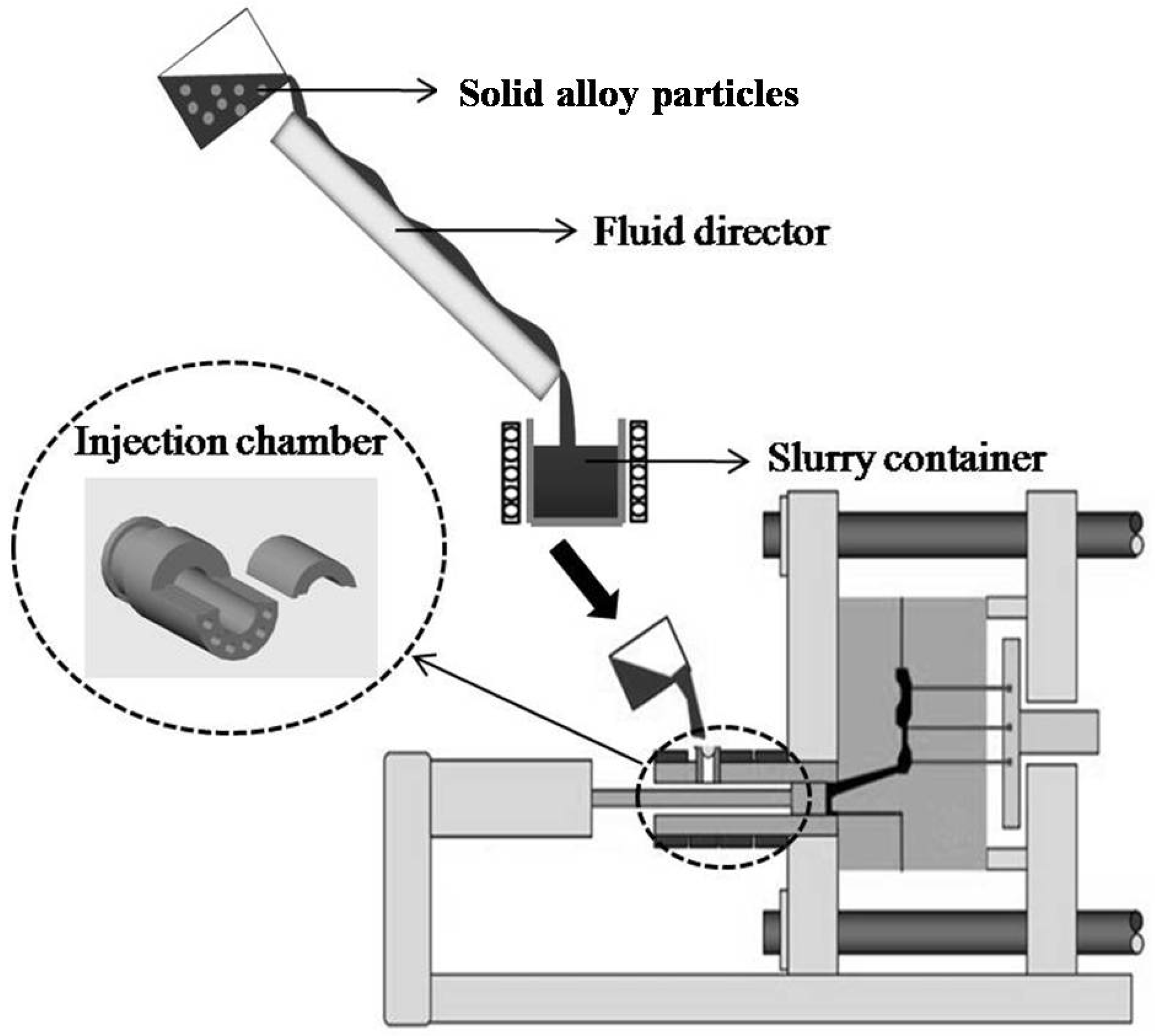
2.1. Slurry Preparation Procedure

Commercial AM60 alloy was used as the experiment material (Ningxia Huayuan Magnesium Industry Group Co., Ltd, Ningxia, China), the actual composition is Mg–6.03Al–0.02Zn–0.32Mn–0.02Si–0.0006Cu–0.0019Fe (in wt. %). Its theoretical liquidus and solidus temperature is 615 °C and 540 °C respectively. Figure 1 shows the phase diagram of this alloy [15]. First, 1.2 kg ingot was melted in resistance furnace, degassed with 1% C2Cl6 at 720 °C and then cooled to 690 °C. Five-percent (mass fraction of melt) solid particles were then added into the melt, followed by stirring within 5 s with a stick. Finally, the melt was poured through a fluid director and kept in a container within a certain amount of time. The operative mechanism behind this method is to promote a rapidly internal cooling effect of the alloy melt and to induce nucleation sites such as high melting refractory heterogeneous phases by the fusion of solid particles, and to construct nucleation condition combined with the further melt cooling due to the heat extraction of the fluid director. Details of the role of the solid particle and the fluid director in this method have been investigated in our previous work [16]. Figure 2 illustrates the melt temperature variation in this process, and points C, D and E represent the melt temperature after solid-liquid mixing, at the exit of the fluid director and after holding in the container, respectively. It should be noted that the melt temperature D at the outlet of the fluid director, which is determined by the melt temperature A and the mixing amount of solid particles, is the key influencing factor for nuclei survival, and this temperature should be kept below the alloy’s liquidus temperature for microstructure refinement. In this experiment, the liquid temperature A of 690 °C and the mixing amount of solid particles of 5% are the optimized results from our previous work [16]. Point E is the slurry temperature for die casting, and this temperature can be adjusted by controlling the cooling of slurry in the container. The precursory solid particles, with size of approximately 5 mm × 5 mm × 5 mm, have the same composition as the liquid alloy and were produced by mechanically fracturing the alloy ingot. However, it should be noted that the size of the solid particles is mainly determined by the melt temperature A. The higher temperature A is needed for the fusion of solid particles if a larger solid particle is used. The fluid director is actually a channel machined on the surface of a low carbon steel block, which has two parallel streams, gathering to one at the middle of block. This design aims to enhance the convection effect of the melt flow to provide ideal conditions for nuclei distribution. Figure 3 demonstrates a detailed structure of the fluid director, and a slope angle of 30° was employed in this experiment.
The container at the exit of the fluid director was a stainless crucible of 100 mm in diameter and 150 mm in length, which was surrounded by resistance wire and refractory material so that its temperature could be kept constant. In order to investigate the microstructure evolution in semi-solid state, when the slurry was cooled to 595 °C and continuously held for 0–480 s, a spot of melt was sucked out with a silica tube and quenched in water. In order to make a comparison, conventional pouring was also performed at 690 °C, and melt was immediately quenched when filling the container.

2.2. Rheo-Diecasting Procedure

Figure 4 shows details of the SIRD process. A conventional cold chamber high pressure die-casting (HPDC) machine DAK450-54RC (FRECH (Shanghai) Die Casting Machine Co., Ltd., Shanghai, China), which has a maximum clamping force of 5000 kN, was employed for forming. After the slurry was held in the container within a certain period, it was transferred and poured directly into the pressure chamber. The pressure chamber, shown in Figure 4, was modified by drilling several axial deep holes around the wall and inserting heating rods with a size of 25 × 300 mm to heat the chamber to 590 °C—this design aims to avoid rapid solidification of the slurry in the chamber. The diecasting mold, coated with lubricating oil, was preheated at 250 °C with a 5212 type mold temperature controller (FRECH (Shanghai) Die Casting Machine Co., Ltd., Shanghai, China). The injection velocity set in this study was 0.5 m/s and 3 m/s, while the boost pressure was 160 MPa. In addition, the liquid die casting experiment was also conducted at 690 °C. Repeating the above die casting procedures, several samples used for microstructure observation and tensile testing were obtained.

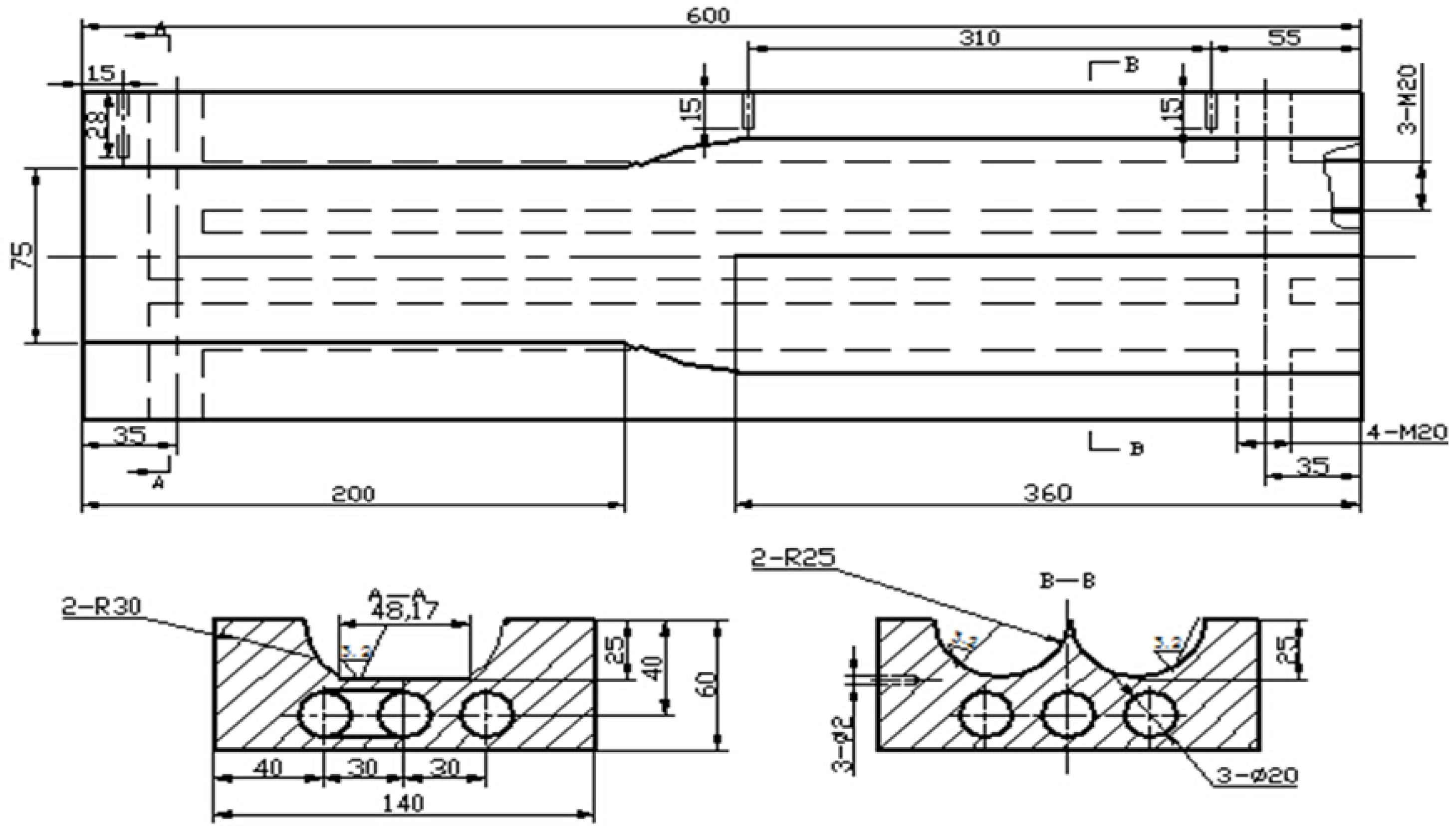
2.3. Microstructure Analysis and Tensile Testing

Figure 5 shows the product and sampling position, as indicated by the circle, for microstructure observation. The four tensile samples were separated from the product and followed by density measurement via the Archimedes method. The average value of 8 samples was used as a density value. Metallographic specimens were cut and the cross sections were polished and then etched by using 10% HCl solution. Optical microscope (OM, NIKON instruments (Shanghai) Co., Ltd., Shanghai, China) and the scanning electron microscope (SEM, NEC Electronics Corporation, Tokyo, Japan) were used to observe the microstructure, while electron probe micro-analyzer (EPMA, SHIMADZU (China) Co., Ltd., Shanghai, China) and energy dispersive (EDS, NEC Electronics Corporation, Tokyo, Japan) were applied for composition examination. Image Proplus6.0 software (Sino-Vision Technology Co., Ltd., Beijing, China) was used for quantitatively analyzing semisolid microstructure. The size and shape factor of α-Mg particles were calculated by D = 2(A/π)1/2 and F = P2/4πA, respectively, where A is average area and P is average perimeter of primary α-Mg particle. Tensile strength was tested by using an electronic material testing machine, and the loading rate of testing was 1.5 mm/s. The value of ultimate tensile strength and elongation was obtained by testing at least 8 samples under the same forming condition. In order to clarify fracture mechanism, SEM was also used to observe fracture surfaces.

3. Results and Discussion

3.1. Preparation of Semisolid AM60 Alloy by Self-Inoculation Process

Figure 6 shows the microstructure of AM60 alloy under conventional pouring and self-inoculation process and then held at 595 °C within different duration times. It shows that the primary α-Mg grains of the alloy from conventional pouring develop dendrites with long secondary arms (Figure 6a). After being treated by the self-inoculation method, however, the dendrites are more likely to be refined, and the microstructure is composed of irregular and rosette α-Mg particles with the size of 20–40 μm (Figure 6b). This indicates an obvious refining effect of the self-inoculation process on this alloy. When the slurry was held at 595 °C in 30 s, it can be seen that the irregular α-Mg evolve into rosette, and a small quantity of globular particles appeared occasionally (Figure 6c). After being held for 60 s, the sharp asperities on the particle surface are degenerated and more particles present as spherical (Figure 6d). As the duration was further prolonged to 240 s and 480 s, the whole microstructure became spheroid grains with uniform distribution and some cucurbit-like agglomerates formed. However, at 480 s, both the reduction of α-Mg quantity and increase of particle size are visibly obvious (Figure 6f).
Figure 7 shows the variations of the particle size and shape factor of α-Mg with duration time at 595 °C. It indicates that the particle size continuously increases, but the shape factor is reduced as the duration time is prolonged. This result implies that spheroidization and coarsening of α-Mg simultaneously proceeded while keeping the slurry in semisolid state.
It is well known that nucleation and the following growing stage are the key factors that determine the final solidification structure of an alloy melt. Different from conventional pouring conditions, in the self-inoculation process, with the appropriate combination of melt treatment temperature and addition amount of solid alloys, it is believed that the nucleation sites could be readily increased by the inhomogeneous structure such as atoms clusters and refractory phases which are induced by fusion of solid alloys [17]. Moreover, when the melt flows on fluid director, nucleation occurs on a channel surface and is also an abundant source for grain multiplication [18]. These factors are beneficial to increase the effective survival of nuclei and thus to obtain a refined microstructure (Figure 6b).
Spheroidization of α-Mg particles in semisolid state, shown in Figure 6 and Figure 7, is actually the ripening and coarsening of solid particles caused by solute diffusion under the driving force of interface energy [19]. In the first stage of continuous keeping of slurry, the equilibrium melting point difference due to the knaggy surface of irregular particles will lead to melting of concave parts but growth of convex areas [20]. It can be expected that this must result in globules and an increase of α-Mg grains in microstructure (Figure 6c,d). Figure 8a presents the magnified α-Mg morphology from the quenched specimen when the slurry was kept within 30 s. It visibly shows the necking and melting of roots of rosette arms and separation into independent particles. Therefore, it can be reasonably concluded that the refined rosette grains, which came from self-inoculation process, provide the resources for α-Mg multiplication in the current slurry preparation. With the proceeding of the diffusion process, it is possible that merging between neighboring particles becomes the main manner for interfacial energy minimization [21]. This suggestion can be demonstrated in Figure 8b, a magnified α-Mg morphology when the slurry is kept within 240 s, that particles A and B connect with only a thin liquid film, while particles B and C fully coalesce with the vanished grain boundary. After that, as the distance between particles increases, the semisolid system reduces its solid/liquid interfacial area through growth of large particles but dissolution of small particles (Figure 6f) [22]. In this work, the suitable microstructures that are suitable for RD can be produced within 60–240 s after self-inoculation pouring. This is an appropriate operating window that is beneficial for slurry reserve and transfer in online production.

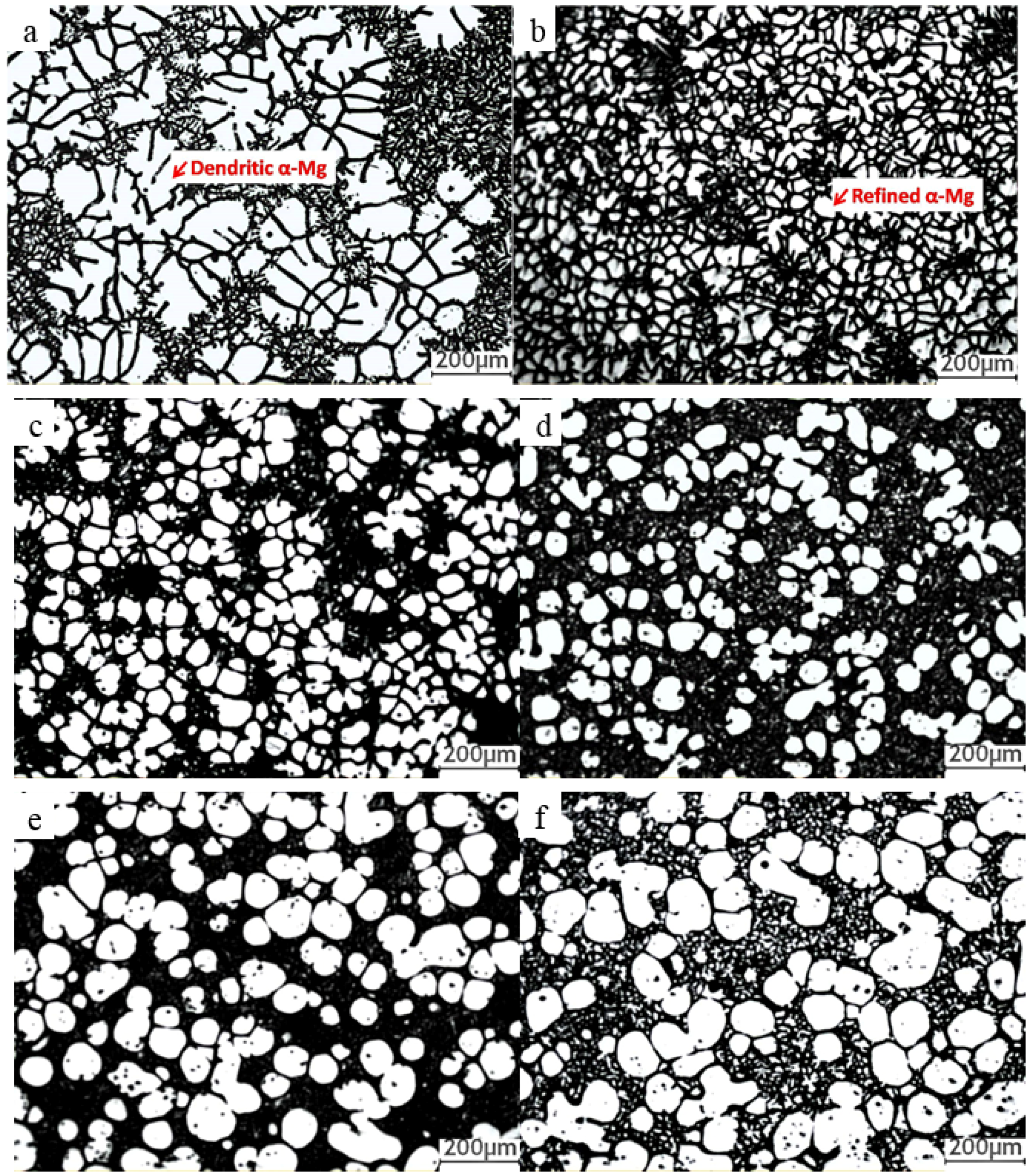
3.2. Microstructural Characteristics and Solidification of AM60 Slurry in SIRD Process

Figure 9 shows the microstructure of AM60 produced by conventional liquid die casting and SIRD with the same injection velocity of 3 m/s. The presence of developed dendritic α-Mg and porosities are frequently observed in the liquid die casting sample (Figure 9a). Comparatively, most of the primary α-Mg in the SIRD sample present as fine and spherical particles, and some small, tiny dendrites which formed in shot chambers existing between primary α-Mg particles. In addition, as a result of rapid solidification of remaining liquid in the die cavity, lots of tiny α-Mg particles, named secondary α-Mg, exist in the liquid matrix (Figure 9b).
Figure 10 shows the detailed microscopic solidification structure of AM60 slurry solidified in the die cavity in SIRD. As shown in Figure 10a, the whole microstructure is featured with the dark spherical primary α-Mg particles, which are surrounded by tiny secondary α-Mg and brighter eutectic mixture. The surface of primary α-Mg is smooth and with no liquid entrapped. From the view under higher magnification (Figure 10b) and under back-scattered electron mode (Figure 10c), it appears that the eutectic mixture of β (Mg17Al12) and the eutectic α-Mg present as an island and a skeleton were appeared on the primary solid surface or in the matrix. Furthermore, cellular or dentate embossment appeared on the solid surface, as indicated by arrow A in Figure 10c. From Figure 10d, it is of interest that the eutectic mixture was mainly divorced and fewer were coupled.
In SIRD, the solidification of the remaining liquid is characterized by the pre-existing primary α-Mg formed in the slurry preparation process. Therefore, the nucleation of remaining liquid is more likely to preferentially occur based on primary α-Mg surface due to the smaller nucleation energy, resulting in the formation of embossment on the solid surface, as shown in Figure 10c. This nucleation manner is followed by independent nucleation and growth of secondary α-Mg in liquid matrix with the decreasing of undercooling in the remaining liquid, as shown by arrow B in Figure 10c. These fine rosette α-Mg particles indicate an extremely high undercooling degree of melt in die cavity due to the low latent heat of semisolid slurry and high thermal conductivity of mold. Eutectic reaction, happening in the later stage of solidification, is a result of Al content in the remaining liquid reaching a eutectic point. However, it can be inferred that the limited pseudo-eutectic composition liquid, due to the low Al content (6%) in AM60 alloy, has led to dependent precipitation of eutectic α-Mg on the surface of secondary α-Mg and finally resulted in the formation of divorced eutectic β (Mg17Al12) phase, as shown in Figure 10d. Therefore, it is difficult to clearly distinguish the eutectic α-Mg from secondary α-Mg particles. Furthermore, the laminar coupled eutectic phase, which is located around β (Mg17Al12) in this figure, is more likely to be the result of lateral growth of β due to the continuous diffusion of Al atoms from liquid to β, but the diffusion of Mg from β to α-Mg becomes difficult owing to the growth of divorced eutectic mixture.
Figure 11 shows the energy dispersive spectrometer (EDS) line scan results across the primary α-Mg and eutectic area. Figure 10a indicates a sharp increase of Al accompanied with a decrease of Mg content when the probe was passing through the matrix, while the contents of these elements in the primary α-Mg were constant. This indicates non-equilibrium solidification of the remaining liquid in the die cavity caused by a high cooling rate, while the solidification in slurry preparation is relatively in equilibrium owing to the sufficient atom diffusion. In the matrix area, two rises in Al are observed when the probe was crossing the eutectic mixture (Figure 11b). The simultaneously sharp increase of Al and Mn content implies some of the AlMn precipitates located in the eutectic area while the subsequent Al increase indicates where the β (Mg17Al12) was located. This result is consistent with Ji study that Al8Mn5 particles were found in positions where the β phase were present in microstructure of rheo-diecasting AM50 alloy [23].
Table 1 shows the quantitative EDS analysis results of the chemical composition of primary α-Mg and different liquid matrix regions shown in Figure 10c,d. It can be found that Al content in the raised surface of primary α-Mg (position 2 in Figure 10c) is slightly higher than that in primary α-Mg but lower than that in secondary α-Mg in matrix (position 3). This result further confirmed the liquid solidification dominated by dependent growth of secondary α-Mg and followed by independent nucleation in liquid matrix. The relatively high content of Al in secondary α-Mg was mainly due to the insufficient diffusion of Al in front of S/L interface. Moreover, the evidently high Al content in eutectic β (position 4) and α-Mg (position 5) confirmed that eutectic reaction happened in the final stage of liquid solidification, which marked the ending of slurry solidification in die cavity.
Figure 12 shows Al distribution in liquid diecasting and SIRD samples detected by EPMA area analysis. The result presents Al segregation between dendrite arms in the liquid die casting sample and in liquid matrix between primary α-Mg phases in the SIRD sample. Previous study of Teng et al. indicated that in semisolid slurry, the presence of solid phase inducing higher Al content in remaining liquid than that in the initial melt alloy [24]. As a result, the quantity of eutectic β (Mg17Al12) in the rheo-diecasting sample is higher than that in the liquid die casting sample. However, it is worth noting that the ultra high cooling rate in the die cavity could efficiently limit the eutectic reaction during secondary solidification of remaining liquid. Thus, the content of β phase can be reduced to certain limits. In this regard, SIRD is a potential process for enhancement of castings property on the basis of microstructure homogenization.

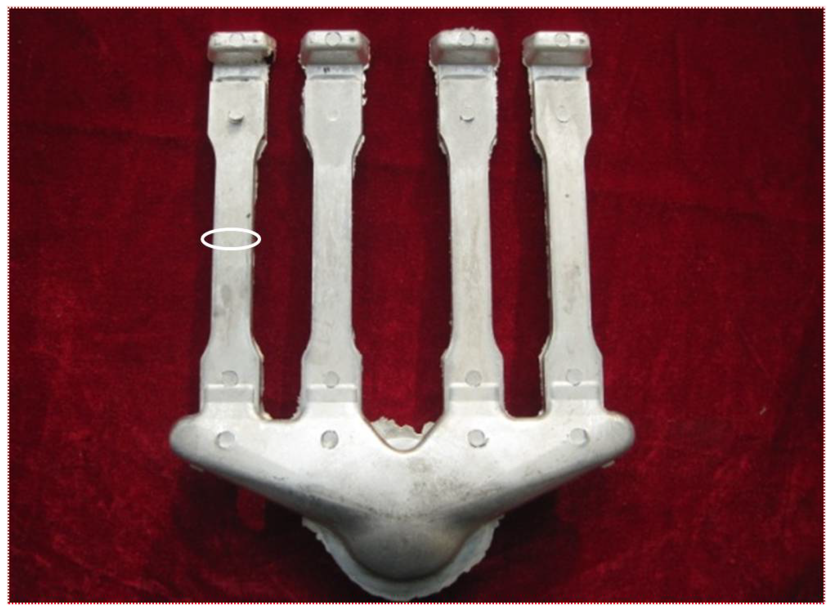
3.3. Mechanical Properties of the Rheo-Diecasting AM60 Alloy

Figure 13 shows the typical fracture surfaces of tensile samples produced by the liquid die casting process (Figure 13a) and SIRD (Figure 13b) with the same injection velocity of 0.5 m/s. The corresponding value of σb and δ is 162 MPa and 5.1% for the liquid die casting sample while 183 MPa and 6.9% for the SIRD sample. Increments of 12.9% and 35.3% of these two indexes are obtained, respectively, under SIRD. From Figure 13a, it is evident that fracture surface appeared to be somewhat brittle as the porosity features were presented. The porosities can also be easily found in metallographic structure of liquid die casting samples as shown in Figure 9a. It is certain that these porosities serve as a crack source, from which the relative low mechanical properties resulted. Comparably, the image of fracture surface of SIRD sample represents some ductile and brittle features with more irregular and accidental surfaces as shown in Figure 13b. This means cracks appeared to initiate at the brittle eutectic β (Mg17Al12) phase and propagate through the secondary solidification region. Therefore, it is concluded that the properties were mainly influenced by the porosity level and eutectic β phase—the reduction of porosity and the decrease and uniform distribution of β phase are beneficial to the enhancement of mechanical properties.
Figure 14 shows the theoretical density value of AM60 alloy and the density of samples produced by liquid die casting and SIRD with different injection velocity. It indicates that SIRD evidently reduces pores in part, thus the improved density values are obtained. In addition, it also implies the reduction of injection velocity was in favor of increasing the sample density, either for liquid die casting or for rheo-diecasting. It seems that this effect was more evident for SIRD castings. This is in agreement with the result shown in Cao et al. that a low injection velocity is more likely to lower the risk for air entrapment in die filling [25]. This is a result of reduced surface turbulence when reducing the injection velocity in the RD process.
Hot tearing can also be frequently observed in the liquid die casting sample but occurred less frequently in the SIRD sample, as shown in Figure 15. It was found that the size can be up to about the millimeter level. In liquid die casting, when the eutectic reaction happens, the remaining liquid between dendrites solidifies with a high rate, thus resulting in instantaneous shrinkage and causing impact stress to dendrites. However, these shrinkage areas cannot be filled due to the interruption of liquid feeding channels caused by dendritic networks. Therefore, the matrix can be easily separated from these empty areas under shrinkage stress. Once the fracture source is generated, the crack will continue to expand and give rise to hot tearing. However, in SIRD, the presence of spherical particles leading to unimpeded feeding channels and the solidification temperature is much lower than that in liquid die casting; these factors promote reduction or elimination of hot tearing in parts as the result of shrinkage reduction.

4. Conclusions

(1).
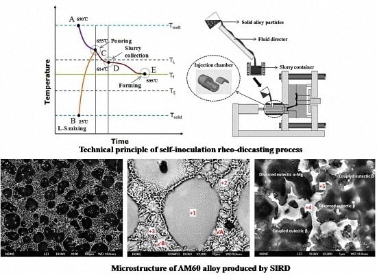
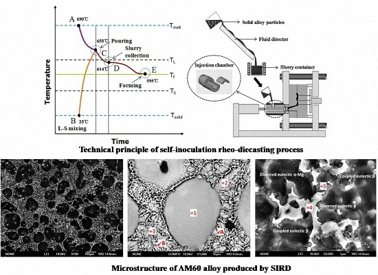
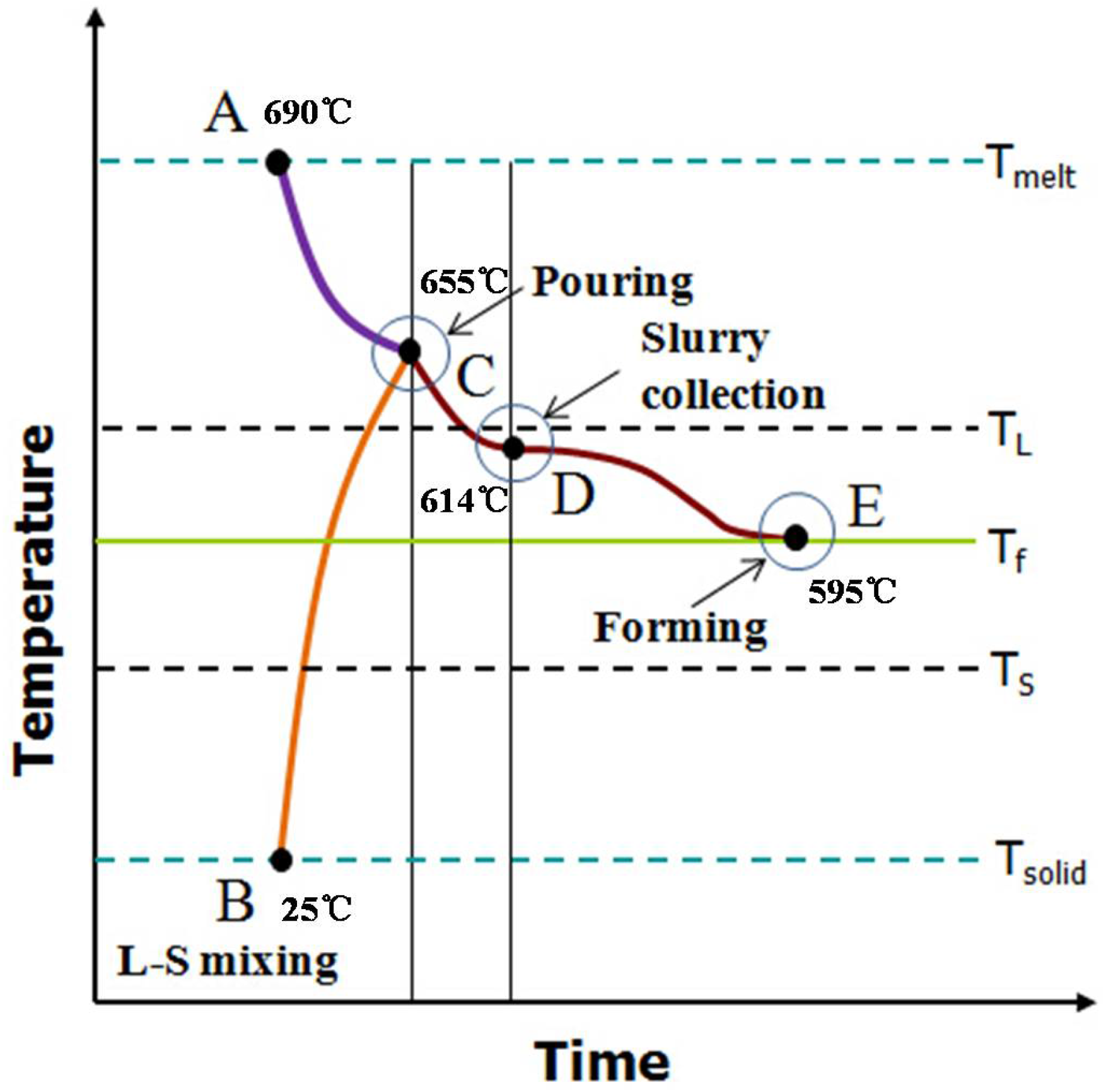
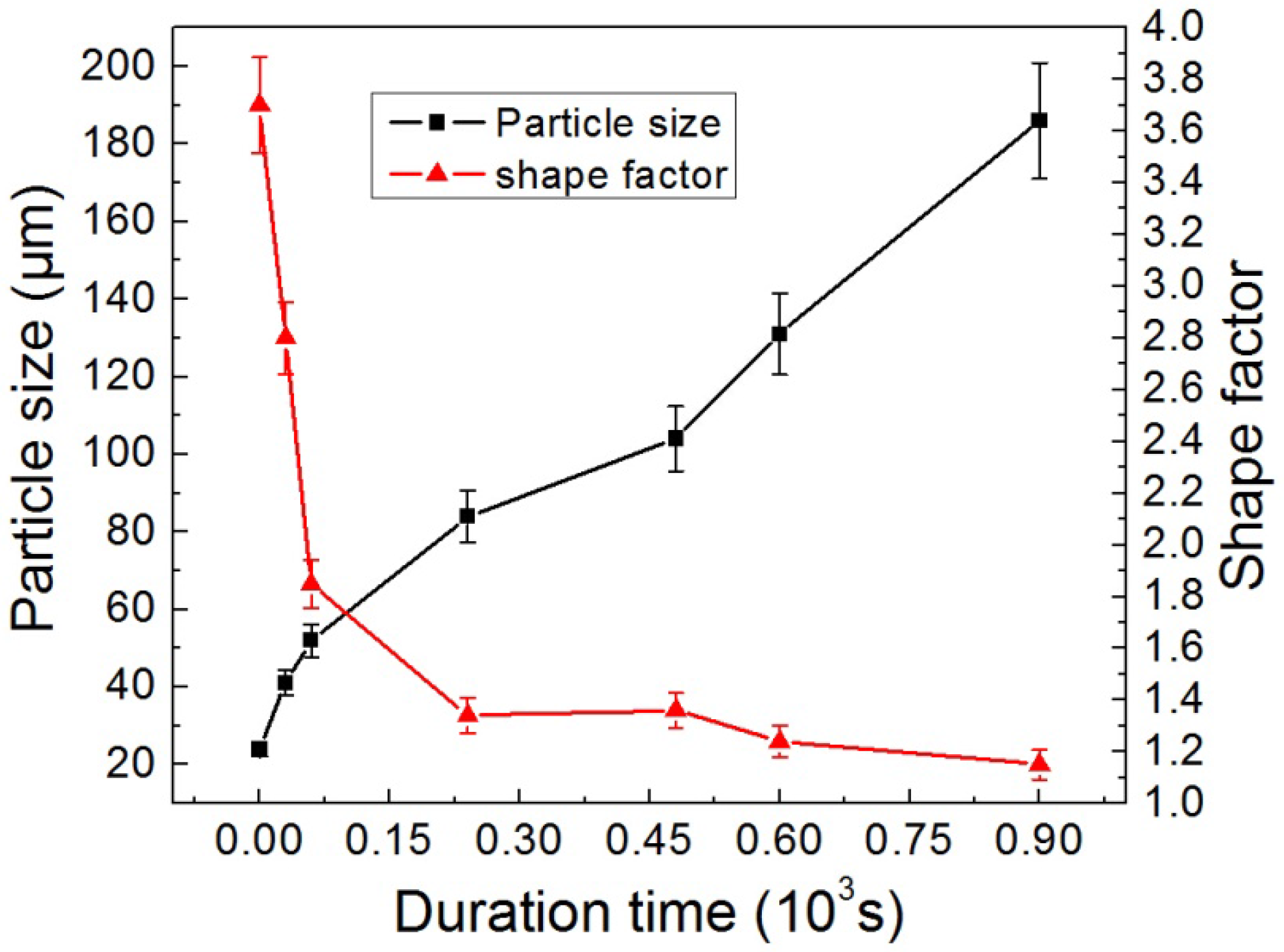
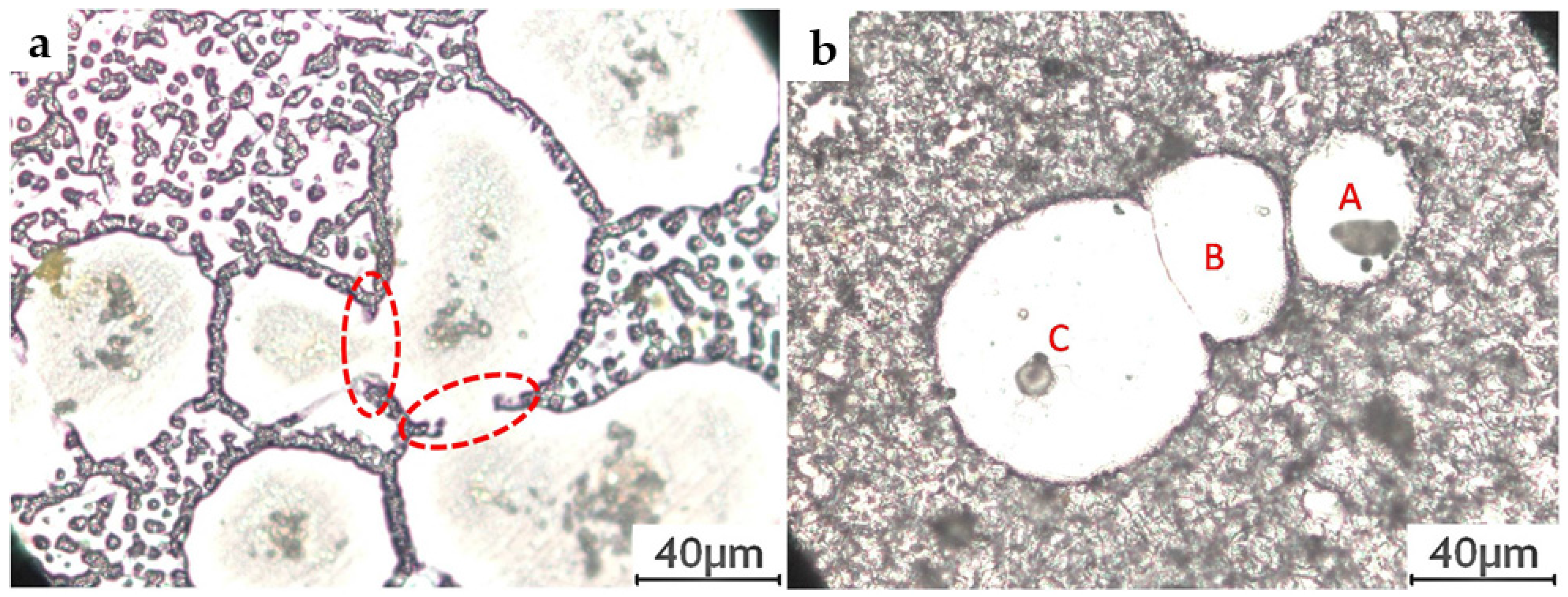
The slurry of AM60 alloy contains refined and irregular α-Mg particles produced with the self-inoculation pouring method, which evolves to a globular and coarse texture when continuously keeping the slurry in semisolid state at 595 °C;
(2).
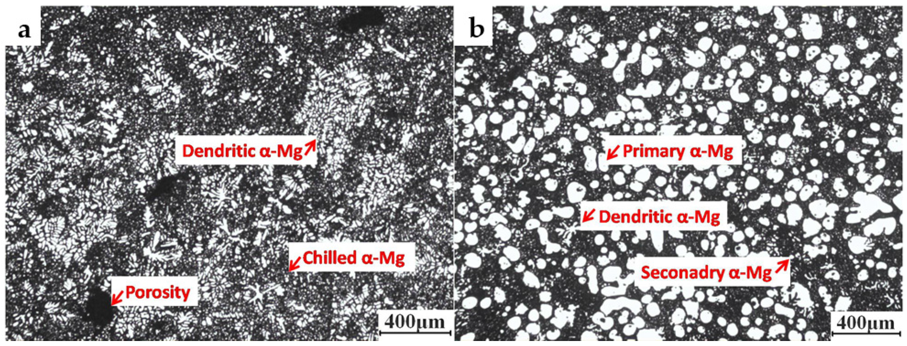
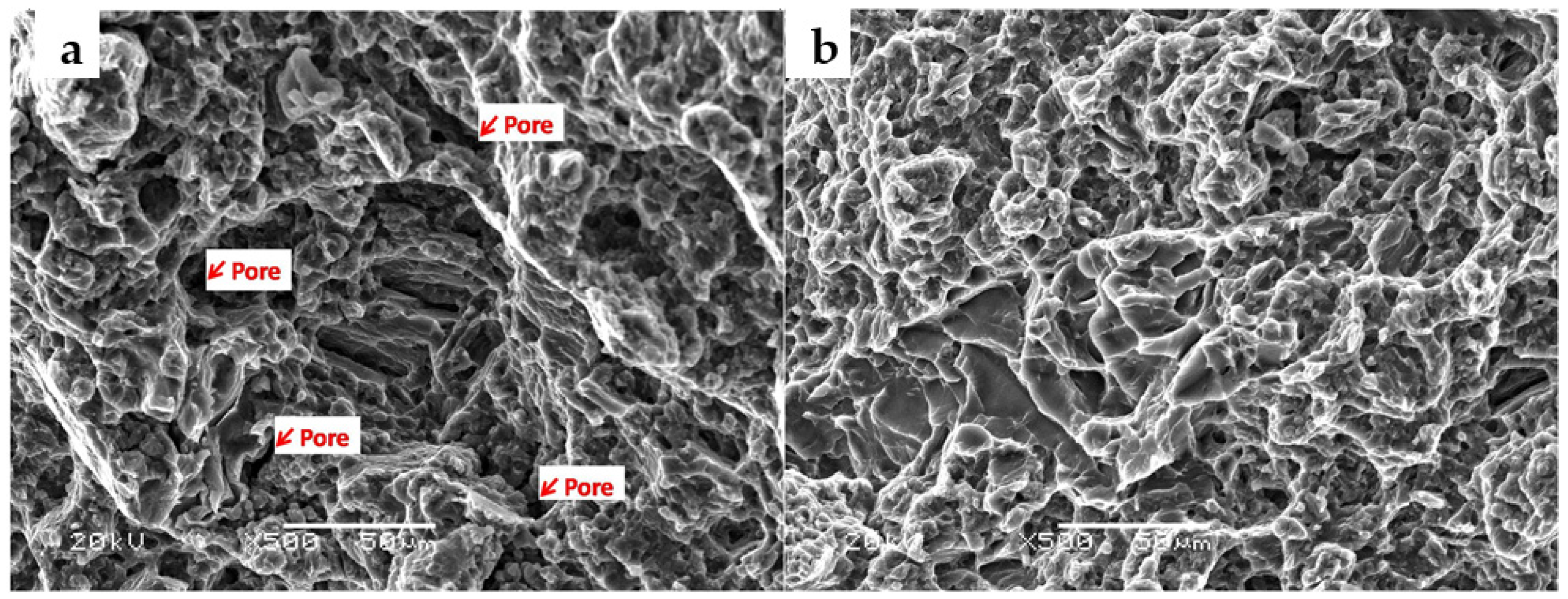
The microstructure of the SIRD AM60 sample was dominated by fine primary α-Mg globules and less tiny dendrites in liquid matrix while the sample from conventional liquid die casting presents as porous dendrites;
(3).
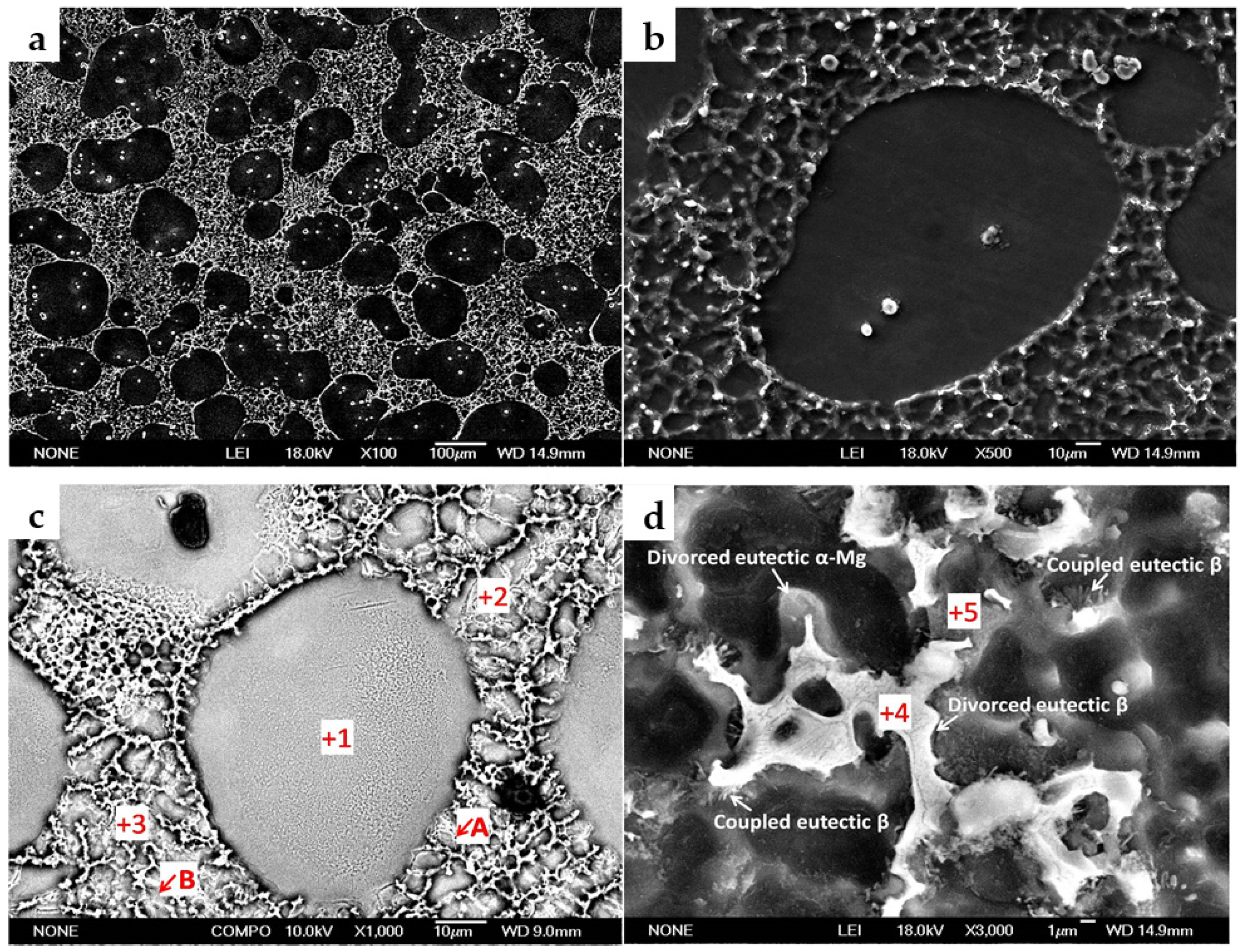
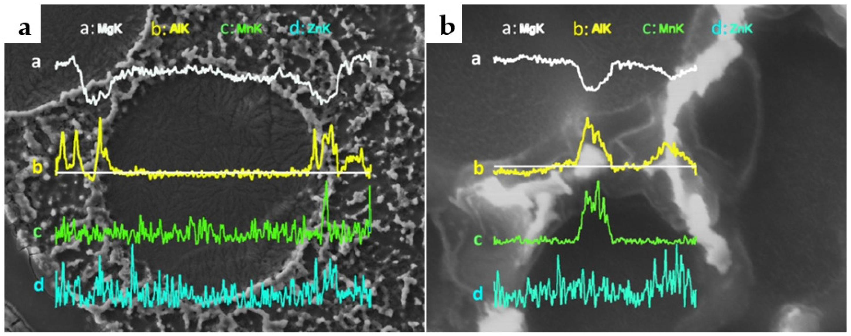
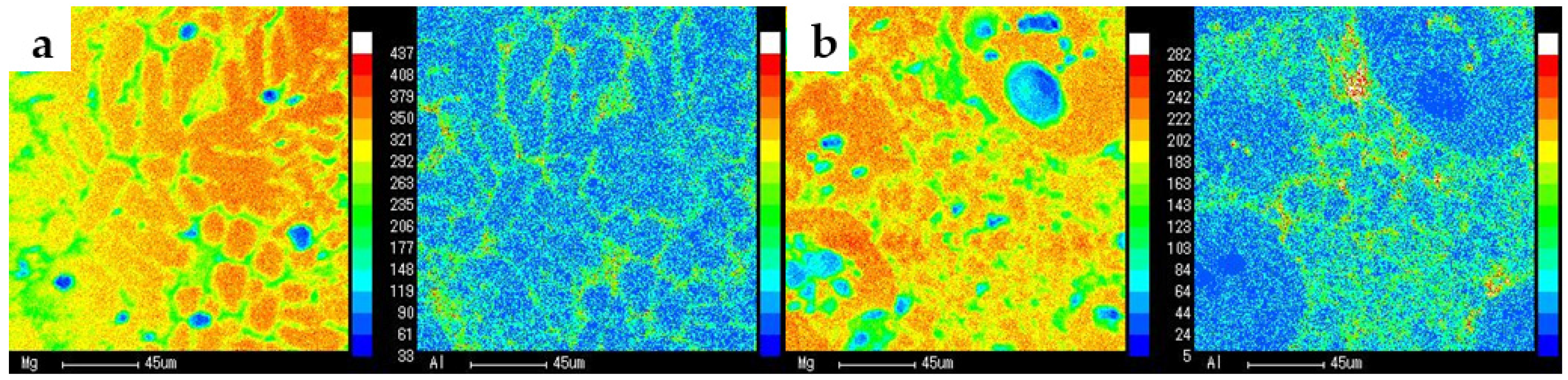
Solidification of the remaining liquid in the die cavity in SIRD occurred in three stages, α-Mg nucleation and growth on primary α-Mg phase which had formed during slurry preparation, α-Mg nucleated independently in liquid, and finally formation of skeleton devoiced eutectic. This solidification is substantially in a non-equilibrium state and resulted in Al segregation in the eutectic mixture;
(4).
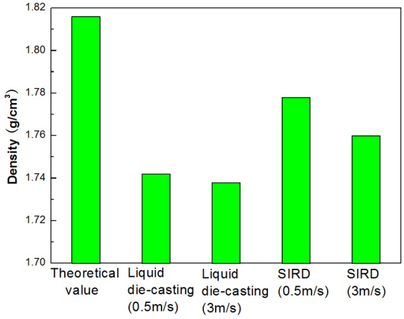
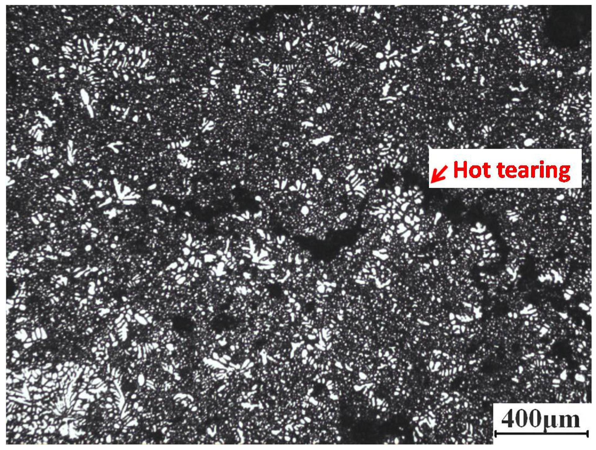
The SIRD process provides products with increased tensile strength and elongation compared to liquid die casting due to the reduced degree of porosity and hot tearing.

Acknowledgments

The authors gratefully acknowledge the financial support from the Zhejiang Provincial Natural Science Foundation of China (LQ16E040001) and National Science Foundation of China (51464031).

Author Contributions

The experimental device and experiments were arranged by Bo Xing and Yuandong Li. The experiments were conducted by Bo Xing, Junyan Feng and Guangshan Hu. The article was written by Bo Xing and revised by Yuandong Li and Chengli Tang.

Conflicts of Interest

The authors declare no conflict of interest.

References

  1. Curle, U.A.; Moller, H.; Wilkins, J.D. Shape rheocasting of high purity aluminium. Scr. Mater. 2011, 64, 479–482. [Google Scholar] [CrossRef]
  2. Janudom, S.; Wannasin, J.; Basem, J.; Wisutmethangoon, S. Characterization of flow behavior of semisolid slurries containing low solid fractions in high-pressure die casting. Acta. Mater. 2013, 61, 6267–6275. [Google Scholar] [CrossRef]
  3. Zhou, B.; Kang, Y.L.; Qi, M.F.; Zhang, H.H.; Zhu, G.M. R-HPDC Process with Forced Convection Mixing Device for Automotive Part of A380 Aluminum Alloy. Materials 2014, 7, 3084–3105. [Google Scholar] [CrossRef]
  4. Zhen, Z.; Qian, M.; Ji, S.; Fan, Z. The effects of rheo-diecasting on the integrity and mechanical properties of Mg–6Al–1Zn. Scr. Mater. 2006, 54, 207–211. [Google Scholar] [CrossRef]
  5. Kirkwood, D.H. Semisolid metal processing. Int. Mater. Rev. 1994, 39, 173–189. [Google Scholar] [CrossRef]
  6. Zhang, Q.; Cao, M.; Cai, J. AlSi9Mg aluminum alloy semisolid slurry preparation by intermediate frequency electromagnetic oscillation process. J. Mater. Process. Technol. 2015, 215, 42–49. [Google Scholar] [CrossRef]
  7. Fan, Z. Development of the rheo-diecasting process for magnesium alloys. Mater. Sci. Eng. A 2005, 413, 72–78. [Google Scholar] [CrossRef]
  8. Qi, M.F.; Kang, Y.L.; Yan, Y.; Zhu, G.M.; Liao, W.N. Comparison of Microstructure and Mechanical Properties of AZ91D Alloy Formed by Rheomolding and High-Pressure Die Casting. J. Mater. Eng. Perform. 2015, 24, 3826–3834. [Google Scholar] [CrossRef]
  9. Jorstad, J.L.; Thieman, M.; Kamm, R. Fundamental Requirements for Slurry Generation in the Sub-Liquidus Casting Process and the Economics of SLC Processing. In Proceedings of 8th International Conference on Semi-Solid Processing of Alloys and Composites, Limassol, Cyprus, 21–23 September 2004.
  10. Martinez, R.A. Formation and Processing of Rheocast Microstructure. Ph.D. Thesis, Massachusetts Institute of Technology, Boston, MA, USA, September 2004. [Google Scholar]
  11. Wu, S.S.; Lv, S.L.; An, P.; Nakae, H. Microstructure and property of rheocasting aluminum-alloy made with indirect ultrasonic vibration process. Mater. Lett. 2012, 73, 150–153. [Google Scholar] [CrossRef]
  12. Canyook, R.; Wannasin, J.; Wisuthmethangkul, S.; Flemings, M.C. Characterization of the microstructure evolution of a semisolid metal slurry during the early stages. Acta. Mater. 2012, 60, 3501–3510. [Google Scholar] [CrossRef]
  13. Saha, D. Novel processing methods and mechanisms to control the cast microstructure in Al based alloys—390 and wrought alloys. Ph.D. Thesis, Worcester Polytechnic Institute, Worcester, MA, USA, May 2005. [Google Scholar]
  14. Findon, M.M. Semi-solid slurry formation via liquid metal mixing. Master’s Thesis, Worcester Polytechnic Institute, Worcester, MA, USA, July 2003. [Google Scholar]
  15. Massalski, T.B.; Okamoto, H. Binary Alloys Phase Diagram; ASM International: Novelty, OH, USA, 1990. [Google Scholar]
  16. Xing, B.; Li, Y.D.; Ma, Y.; Chen, T.J.; Hao, Y. Preparation of non-dendritic microstructure of AM60 alloy for rheo-forming using self-inoculation method. Int. J. Cast. Metal. Res. 2012, 25, 232–238. [Google Scholar]
  17. Guo, H.M.; Wang, L.J.; Wang, Q.; Yang, X.J. Effects of Solid-Liquid Mixing on Microstructure of Semi-Solid A356 Aluminum Alloy. Metall. Mater. Trans. B. 2014, 45, 1490–1495. [Google Scholar] [CrossRef]
  18. Guan, R.G.; Cao, F.R.; Chen, L.Q.; Li, J.P.; Wang, C. Dynamical solidification behaviors and microstructural evolution during vibrating wavelike sloping plate process. J. Mater. Process. Technol. 2009, 209, 2592–2601. [Google Scholar] [CrossRef]
  19. Flemings, M.C. Coarsening in solidification processing. Mater. Trans. 2005, 46, 895–900. [Google Scholar] [CrossRef]
  20. Terzi, S.; Salvo, L.; Suery, M.; Dahle, A.K.; Boller, E. Coarsening mechanisms in a dendritic Al–10% Cu alloy. Acta Mater. 2010, 58, 20–30. [Google Scholar] [CrossRef]
  21. Jiang, J.F.; Wang, Y.; Atkinson, H.V. Microstructural coarsening of 7005 aluminum alloy semisolid billets with high solid fraction. Mater. Charact. 2014, 90, 52–61. [Google Scholar] [CrossRef]
  22. Ji, S.; Roberts, K.; Fan, Z. Isothermal coarsening of fine and spherical particles in semisolid slurry of Mg–9Al–1Zn alloy under low shear. Scr. Mater. 2006, 55, 971–974. [Google Scholar] [CrossRef]
  23. Ji, S.; Zhen, Z.; Fan, Z. Effects of rheo-die casting process on the microstructure and mechanical properties of AM50 magnesium alloy. Mater. Sci. Technol. 2005, 21, 1019–1024. [Google Scholar] [CrossRef]
  24. Teng, H.T.; Zhang, X.L.; Zhang, Z.T.; Li, T.J.; Cockcroft, S. Research on microstructures of sub-rapidly solidified AZ61 magnesium alloy. Mater. Charact. 2009, 60, 482–486. [Google Scholar] [CrossRef]
  25. Cao, H.; Wessen, M.; Granath, O. Effect of injection velocity on porosity formation in rheocast Al component using rheometal process. Int. J. Cast. Met. Res. 2010, 23, 158–163. [Google Scholar] [CrossRef]
Figure 1. Phase diagram of AM60 alloy.
Metals 06 00069 g001
Figure 2. Schematic diagram of temperature variation during SIRD, where TL and TS is the liquidus and solidus temperature of AM60 alloy, respectively.
Metals 06 00069 g002
Figure 3. Schematic of fluid director structure.
Metals 06 00069 g003
Figure 4. Schematic diagram of SIRD process.
Metals 06 00069 g004
Figure 5. Schematic diagram of the rheo-diecasting product.
Metals 06 00069 g005
Figure 6. Microstructure of AM60 alloy under conventional pouring (a) and poured by self-inoculation process and then held at 595 °C with (b) 0 s; (c) 30 s; (d) 60 s; (e) 240 s; (f) 480 s.
Metals 06 00069 g006
Figure 7. Effect of duration time on particle size and shape factor of primary α-Mg phase.
Metals 06 00069 g007
Figure 8. Separation of α-Mg rosettes (a) and merger between neighboring α-Mg particles (b).
Metals 06 00069 g008
Figure 9. Microstructure of AM60 produced by conventional liquid die casting (a) and SIRD (b).
Metals 06 00069 g009
Figure 10. SEM micrographs showing detailed microstructure of the SIRD AM60 sample. (a) at lower magnification showing the distribution of primary α-Mg and eutectics; (b) at higher magnification and (c) back-scattered electron image showing detailed morphology of primary α-Mg; (d) at higher magnification showing the eutectic morphology.
Metals 06 00069 g010
Figure 11. EDS line scan analyses of compositional variation across primary α-Mg (a) and eutectics (b).
Metals 06 00069 g011
Figure 12. Results from EPMA area analysis of AM60 sample under (a) liquid diecasting and (b) SIRD.
Metals 06 00069 g012
Figure 13. SEM images of tensile fracture for (a) liquid die casting and (b) rheo-diecasting AM60 alloy.
Metals 06 00069 g013
Figure 14. Density of AM60 alloy under different processes.
Metals 06 00069 g014
Figure 15. Microstructure of hot tearing in AM60 sample produced by liquid die casting.
Metals 06 00069 g015
Table 1. EDS analysis on different position of rheo-diecasted AM60 (wt. %/at. %).
PositionMgAlMnZnOTotal
194.73/93.981.81/1.620.34/0.1550.4/0.152.7/4.11100
294.6/94.21.9/1.70.52/0.230.56/0.212.42/3.66100
391.59/90.092.83/2.510.39/0.170.46/0.174.72/7.06100
460.37/60.2431.1/27.960.26/0.110.76/0.287.52/11.4100
583.85/82.7611.02/9.80.24/0.1-/-4.89/7.33100

