
Cyclic Testing on Seismic Behavior of Segmental Assembled CFST Bridge Pier with External Replaceable Energy Dissipator


1
Department of Civil Engineering, Zhejiang University City College, Hangzhou 310015, China
2
Zhejiang Engineering Research Center of Intelligent Urban Infrastructure, Hangzhou 310015, China
3
Key Laboratory of Safe Construction and Intelligent Maintenance for Urban Shield Tunnels of Zhejiang Province, Hangzhou 310015, China
4
School of Environment and Civil Engineering, Jiangnan University, Wuxi 214122, China
5
Department of Civil Engineering, Zhejiang University, Hangzhou 310058, China
6
Department of Civil Engineering, Tongji University, Shanghai 200092, China
*
Author to whom correspondence should be addressed.
Metals 2022, 12(7), 1156; https://doi.org/10.3390/met12071156
Submission received: 3 June 2022
/
Revised: 23 June 2022
/
Accepted: 30 June 2022
/
Published: 6 July 2022
(This article belongs to the Special Issue Experimental and Numerical Analysis of Composite Contribution Structures)
Abstract
:In 2009–2022, to meet the requirement of resilient bridge pier structure (e.g., earthquake resistance, energy dissipation, isolation, resilience) for rapid repair after earthquakes and to improve the suitability of precast segmental bridge piers in medium- and high-intensity areas, a segmental assembled CFST bridge pier with external replaceable energy dissipator was proposed. Based on ABAQUS finite element analysis software, the finite element model of the CFST pier is established to analyze the force of the external replaceable energy dissipator, and the feasibility of the external energy dissipator is verified. Thereafter, two groups of segmentally assembled CFST pier model structures were tested for seismic behavior under reciprocating loading. Non-linear mechanical behaviors, such as restoring force-displacement hysteresis, loss of prestressing, and opening of the indirect joint of a segmented precast assembled pier, are analyzed. The results show that compared with a CFST pier with an energy dissipator, the lateral bearing capacity of the CFST pier with an external energy dissipator is increased by 32.8%, the energy dissipation capacity is also significantly improved, the opening size of joints between segments is reduced, and the overall damage of the CFST pier is concentrated on the energy dissipator, which is convenient for rapid disassembly and replacement. At the same time, the seismic performance of the CFST pier after replacing the energy dissipator is analyzed. The results show that the replacement of the external energy dissipator will not affect the seismic performance of a segmental assembled pier.
1. Introduction
In order to reduce the interference of bridge construction on the surrounding environment and traffic, improve the construction efficiency of bridges across rivers, and realize the concept of rapid, green, and industrialized construction, the rapid bridge construction technology of factory prefabrication and on-site assembly has attracted extensive attention in recent years. The prefabrication and production of segmental assembled piers in a factory provide the modern pier structure with high construction quality and faster construction on site [1]. The self-resetting segmental assembled concrete pier is a structural system that divides the pier into several segments with unconnected reinforcement according to a certain method. Each segment is extruded and assembled to form a whole with post-tensioned prestressed reinforcement. As the segmental assembled pier can be prefabricated in the factory, it has less interference to the environment and a shorter construction period. More importantly, the existence of prestressed tendons greatly increases the integrity and self-resetting ability of piers. To a certain extent, this technology can effectively control the residual deformation of piers, which has become a feasible scheme for rapid green construction and solving the large residual deformation of traditional reinforced concrete piers in the aftermath of an earthquake [2].
Combined with the fabricated assembly design and rapid construction technology, as well as the fabricated structure technology based on recoverable functions after an earthquake, researchers have carried out preliminary research on fabricated assembled self-resetting piers. Under a reciprocating earthquake, the joints between segments will open and close, and the local rocking interface at the joint will bear large local pressure, which would cause the premature crushing of local concrete [3]. In order to solve this problem, some researchers put forward a variety of measures to improve the bearing capacity of local concrete: Taira [4] proposed for the first time that steel tube and concrete could be combined as pier segments, and the initial tensile force of prestressing and axial pressure of the pier were borne by concrete and steel tubes. Chou and Chen [5] designed the segments as steel tube confined concrete. According to the results of the quasi-static loading test, it was found that the segment-assembled CFST piers had good ductility and self-reset ability. ElGawady and Dawood [6] used fiber-reinforced composite materials (FRP) to constrain concrete segments and found that this method could significantly improve the bearing capacity of bridge piers. Sideris [7] et al. applied silicone resin at the joints of self-reset bridge piers with box sections and proposed a special “slip-swing mixed system”. The study shows that the system can reduce the seismic force and section damage by adjusting the slip momentum at the joint. Mander [8] designed a no-damage method of a segmental assembled pier. The post-tensioned unbonded prestressed reinforcement was used for the axis of a swing pier, and the rubber plate was set at the steel–steel contact interface as the swing interface, reducing the local concrete damage. Hewes [9] et al. experimented on the plastic hinge area at the bottom of the pier, whose body was wrapped with steel pipe, in order to take full advantage of the concrete-filled steel tube and prevent damage to the pier in the plastic hinge area. However, it was found that this led to the plastic hinge moving up to the upper segment joint, resulting in serious damage to the segment joint. Hu Liang [10] researched the seismic performance of segmental-assembled concrete-filled steel tubular pier, the failure mode of the segmental assembled pier was clarified, and a two-parameter exponential constitutive model of concrete-filled steel tubular constraint was proposed. This study provided a reference for the seismic calculation, analysis, and design application of piers. Jia Junfeng [11] introduced a design method for the main components of a prestressed segmental assembled concrete-filled steel tubular pier and conducted a quasi-static test on it. It was found that the energy dissipation capacity of this kind of pier is poor when there is no additional energy dissipator. The additional steel pipe connection at the segmental assembly joint can improve the energy dissipation effect; however, it increases the residual displacement of the pier top.
For segmental concrete-filled steel tubular piers, the lack of energy dissipation capacity is also a serious problem. In order to improve the energy dissipation capacity of segmental assembled piers, scholars around the world also carried out a series of studies: Ou and Wang [12,13,14] further studied the self-reset performance of segmental piers and the bending failure in the plastic hinge area at the bottom of the pier by conducting the opening test of the inter-segmental joints of the pier under lateral loading. The experimental results show that after the introduction of unbonded post-tensioning, the strain of the prestressed tendons near the joints of segmenting bridge piers will be distributed in a larger length when the joints between segmenting joints open under the action of the horizontal load, thus effectively avoiding the local yield of the prestressed tendons. At the same time, the problem of poor energy dissipation capacity of the prestressed segmental pier is also highlighted in their research. Han [15] et al. conducted a pseudo-static test on three 1/3 scale post-tensioned prestressed prefabricated double-column piers. In the bottom area of the piers, a steel-tube-confined concrete section with a reduced section and an external replaceable energy-dissipating device was adopted, and the results showed that the specimens had good energy dissipation capacity and small damage to the bottom of the piers. Wei Zanyang [16] designed a prefabricated pier connection structure based on the friction of the self-locking principle. Based on ABAQUS, the model was established to analyze the influence of various parameters on the pier structure. The results showed that increasing the friction coefficient, slope, thickness of outer sleeve steel plate, and axial compression ratio of the pier can improve the seismic performance of the pier. Varela [17] et al. built rubber bearings between the pier bottom and the cap and connected them with shape memory alloy (SMA) to enhance the energy dissipation capacity of the pier. ElGawad [18] researched the double-column self-resetting fabricated pier with an angle steel damper with a quasi-static test. The research showed that the energy dissipation capacity of a fabricated assembled pier was increased by 75% compared to that of a fabricated assembled pier without an angle steel damper. Before the offset rate was 4%, the residual displacement was about 10%. Later, due to the fracture of the angle steel damper, the energy dissipation capacity of the pier was reduced, and the concrete pier body was basically free of damage. Hao [19] et al. conducted a quasi-static test on the prefabricated bridge pier with a tension-only energy dissipation device (TEED) and basalt fiber reinforced composite material (BFRP) and found that there was no obvious damage to the bridge pier wrapped with BFRP. Furthermore, TEED improved the energy dissipation capacity of the pier while controlling the residual displacement at a small level. Thus, making piers easy to repair after an earthquake. Zhang Qiang [20] proposed two kinds of structures of fabricated and assembled concrete-filled steel tubular piers with post-tensioned prestressed segments and concrete-filled steel tubular piers with high-strength bolts. The relationship between force and displacement at the top of each fabricated segment and the relationship between bending moment and curvature at the contact surface of each segment were deduced. Based on ABAQUS, the pier was numerically analyzed and compared with the test results. It was found that this pier took full advantage of the high performance of concrete-filled steel tubules and improved the energy consumption capacity of segmental assembled piers, plastic hinge failure of ordinary segmental assembled piers, and production efficiency, and was conducive to popularization in high and medium seismic risk areas.
The existing research shows that the prefabricated pier has a strong self-reset ability and high ductility by using a post-tensioned non-bonded prestressed connection mode. The application of the CFST structure can effectively reduce the local damage to concrete caused by stress concentration and improve the energy dissipation capacity of bridge piers by increasing energy dissipation components. However, the existing energy dissipation parts still have the following shortcomings: it is not easy to replace the internal energy dissipation steel bars after being damaged, the energy dissipation steel bars must be grouted twice after being assembled in sections, the internal shape memory alloy is expensive and its mechanical properties are easily affected by the environment, the connection structure of external energy dissipation components and post-earthquake replacements are more complicated.
Aiming at the existing energy dissipator, the bearing capacity of energy dissipation and the way to improve the effect is not obvious because of the lack of ductility and the large residual deformation. Such problems are difficult to change. This paper puts forward a new type of external energy dissipator. The energy dissipation apparatus has a simple structure, is stable and reliable, has a good shear and earthquake energy dissipation capacity, is easy to repair and replace, etc. Under the action of an earthquake, the opening deformation of the pier joint can be limited, and the energy can be dissipated by plastic deformation through an energy dissipator. Firstly, the ABAQUS platform was used to establish the relevant specimen model, and the analysis was carried out to verify the feasibility of the external energy dissipator. After that, the energy dissipation capacity, residual displacement, stiffness degradation, and strain of the energy-dissipator of segmental CFST piers were studied by a quasi-static reciprocating loading test to evaluate their seismic performance. Finally, the seismic performance changes of CFST piers before and after the replacement of the external energy dissipator are compared to verify the replaceability of the energy dissipator.
2. Numerical Simulation Based on Finite Element Method
Based on previous research [21], it was found that the external energy dissipator could achieve the purpose of controllable loss. In order to verify the feasibility of the scheme and provide a basis and reference for subsequent tests, the numerical models of the CFST-R (segmental assembled CFST pier with external replaceable energy dissipator) and CFST-0 specimens (segmental assembled pier) are established in ABAQUS, and the simulation results are analyzed.
2.1. Material Model
The trilinear model is used for finite element analysis of steel, and the slope of the elastic stage curve is the elastic modulus of steel , where . When reaching the yield strength of steel , the material enters the strengthening stage. We assume the slope of the curve is 0.01. Until the steel reaches the ultimate strength the slope of the curve is zero. Where the - function of steel can be expressed by:
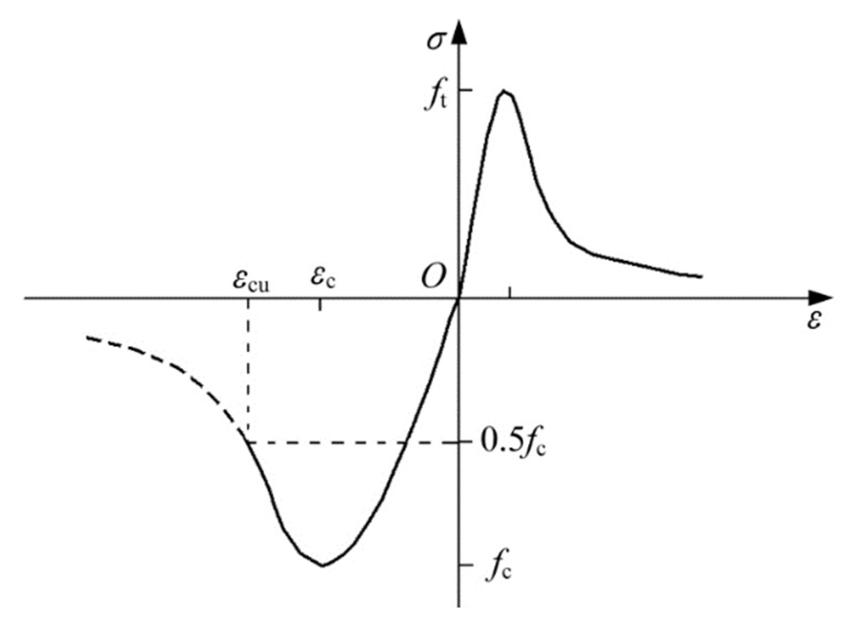
The plastic damage model provided by ABAQUS is used to simulate the concrete, the constitutive relationship of concrete adopts the recommended formula in the Code for Design of Concrete Structures (GB50010-2010) [22]. The constitutive relation of concrete is shown in Figure 1, where the expansion angle is 30°, flow potential offset rate is 0.1, ratio of biaxial ultimate compressive strength to uniaxial ultimate compressive strength is 1.16, stress ratio is 0.667. When the viscosity parameter adopts the default value = 0 provided by ABAQUS, the operation result does not converge. According to the relevant research experience [23], it is suggested that should be 0.0005.
2.2. Element Definition
The finite element model in this paper consists of a steel pipe segment, concrete, prestressed reinforcement, energy dissipation elements, and a ground beam. For the solid part of the pier body (concrete section, steel pipe, energy dissipation element, and ground beam), the reduced integral element (C3D8R) was adopted, which can avoid the influence of grid distortion on displacement accuracy and the influence of shear self-locking on structural stiffness. The truss element (T3D2) is for unbonded prestressed tendons in this study, which is suitable for simulating slender tension–compression members that transmit only axial force.
2.3. Mesh Size
Mesh generation is an important part of the finite element model because the number of meshes not only directly affects the accuracy of the calculation results, but also affects the calculation efficiency. In order to ensure the convergence and accuracy of the calculation, hexahedral mesh and structured meshing technology are used in the mesh generation, so as to obtain better calculation accuracy and reduce the calculation workload. Through the sensitivity analysis of the grid, considering the calculation efficiency and calculation accuracy, the overall grid density of the steel tube, concrete, and ground beam is 20 mm, the key part (the connection between the energy dissipation element and the steel tube) is 10 mm, and the grid density of the energy dissipation element is 1 mm [24].
2.4. Contact and Boundary Conditions
Surface–surface contact is used for the joints between segments in this paper. The normal behavior adopts the definition of “hard contact” that transmits pressure only when the gap between the contact surfaces is 0; that is, the normal pressure is transmitted when the surfaces are in contact, and the node constraint fails when they are separated. The tangential behavior adopts the “penalty friction”, which defines the interface friction characteristics with the friction coefficient, and the friction coefficient is 0.4 [25]. A tie is used between the steel pipe and concrete beam.
For simplicity, the piers in this paper are designed as cantilever structures, the bottom end of the pier is fixed, all degrees of freedom are restrained, and the top end of the pier is free without any restraint. In order to obtain the reaction force at the bottom of the pier, a reference point is established in the center of the base, the coupling method is used to couple the base center and the reference point, and the translational and rotational degrees of freedom of the reference point in three directions are constrained, achieving the consolidation effect of the pier bottom.
2.5. Unbonded Steel Strand or Strand Wire
The prestressed reinforcement is designed as unbonded prestressed reinforcement. Therefore, the prestressed reinforcement can be divided into three parts. The part of the prestressed reinforcement extending into the loading end is embedded and connected with the foundation, and the other parts are not treated to simulate the unbonded state of the prestressed reinforcement between the concrete. There are three steps in the analysis. The first step is to load the prestress, the second step is to load the gravity and dead load axial pressure, and the third step is to apply the horizontal low cycle to reset the load.
2.6. Analysis Step Settings
In order to make the calculation results closer to the actual force, the model set up three analysis steps. In the first analysis step, a 20 kN axial force was applied on the top of the pier for preloading, the initial increment step size was 0.001, the maximum was 0.01, and the maximum increment step number was 1000, which continued to the next analysis step. In the second analysis step, the initial increment step size was 0.1, the maximum increment step size was 1, the maximum increment step number was 1000, and the axial force of 180 kN was applied to the pier top. In the third analysis step, the horizontal load was applied at the top of the pier, and the horizontal load was controlled by displacement, which usually has good convergence.
2.7. Method for Solving Non-Linear Equations
ABAQUS finite element analysis involves material nonlinearity and geometric nonlinearity, so non-linear equations need to be solved in the calculation process. The iterative method, incremental method, and incremental iterative method are the main methods to solve non-linear equations. The incremental iterative method has the advantages of the former two, so it is selected in this paper. For the incremental method, ABAQUS uses the automatic incremental method. For the iterative method, ABAQUS provides three methods: Newton method, modified Newton method, and quasi-Newton method. The Newton method has the largest amount of iterative calculation, but its convergence is good, and its calculation speed is fast, so we chose the Newton method.
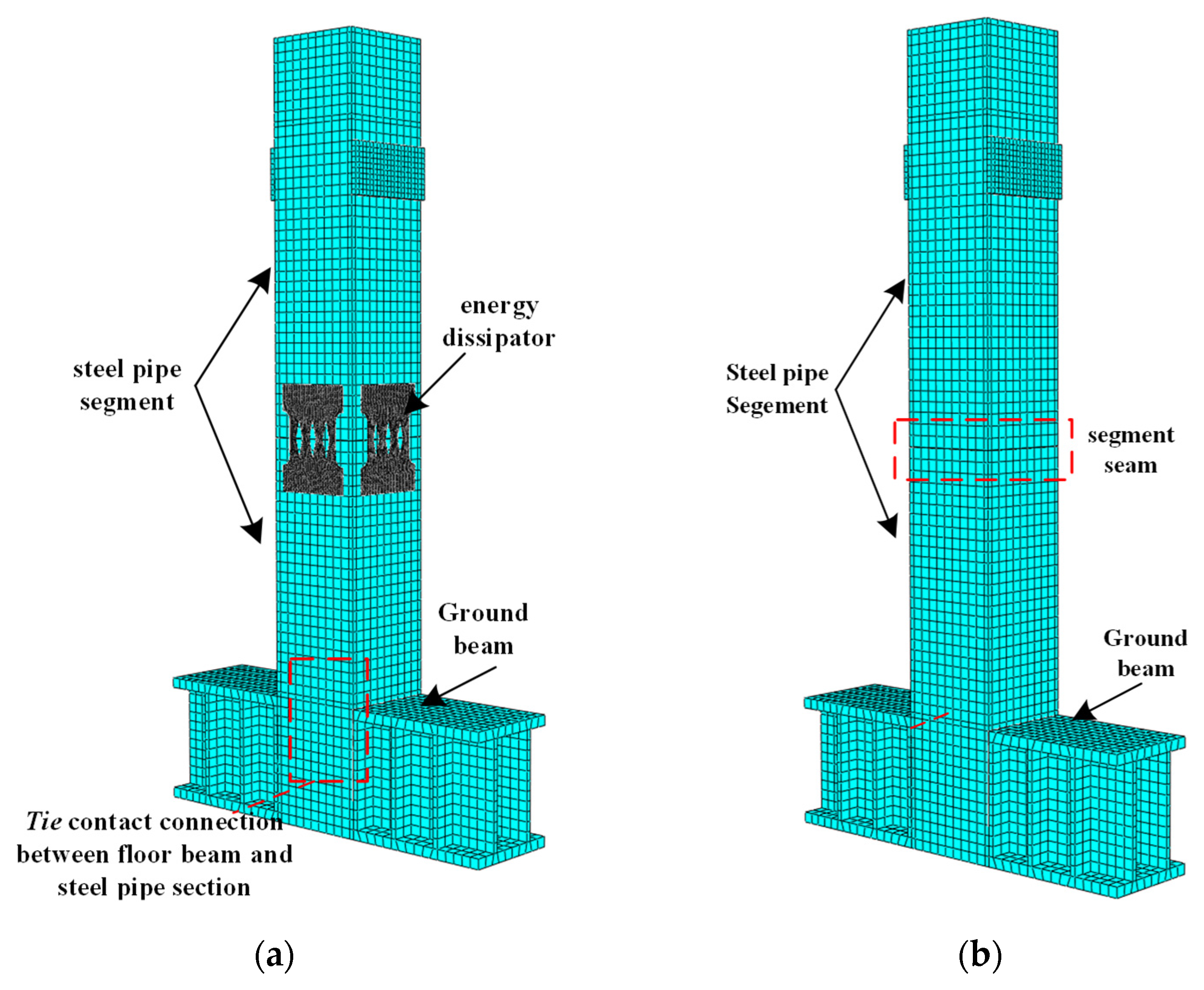
The final finite element models of CFST-R and CFST-0 specimens are shown in Figure 2.
2.8. Result Analysis
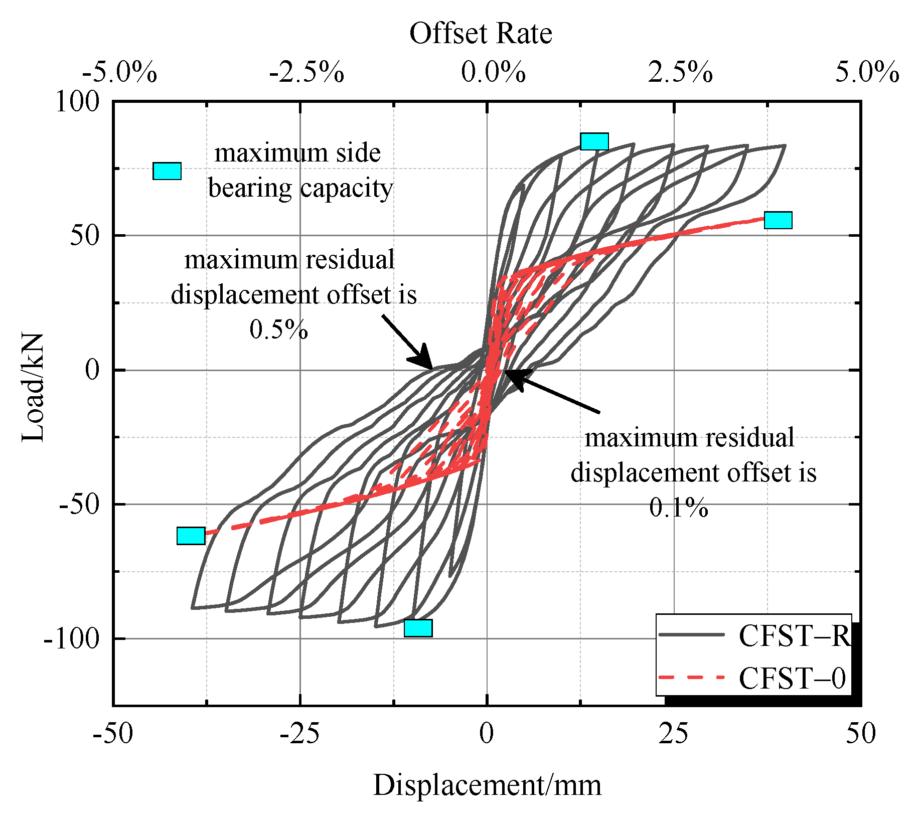
Figure 3 shows the comparison of hysteretic curves between CFST-R (CFST pier with external energy dissipator) and CFST-0 (segmental assembled CFST pier).
The hysteretic curve of the CFST-R specimen has a significant flag mechanical shape. At the initial stage of loading, the horizontal bearing capacity increased linearly with the loading displacement. When the offset rate reached 1.5%, there was a small opening in the joint between segments, and the lateral bearing capacity reached the maximum. The maximum side bearing capacity of the specimen under positive and negative loading was 95.03 kN and 84.78 kN, respectively. The maximum residual displacement offset rate of the test piece was 0.5%, which is less than the limit value of the residual displacement (1.0%) corresponding to the structural repairable standard specified in the Japanese code, indicating that the CFST-R specimen has a good self-resetting ability.
The hysteretic character of the CFST-0 specimen, especially pinching, was significant, and the energy dissipation capacity was significantly reduced compared with CFST-R. When the displacement reached 40 mm (offset rate 4%), the lateral bearing capacity was 60% of CFST-R, while the maximum residual displacement offset rate was only 0.1%, and the self-resetting ability was better.
The results show that the external energy dissipator can improve the energy dissipation capacity, lateral bearing capacity, and other seismic performance of the CFST pier, but at the same time, it will slightly reduce the self-resetting capacity of the pier. The analysis of the finite element model proves the feasibility of the external energy dissipator.
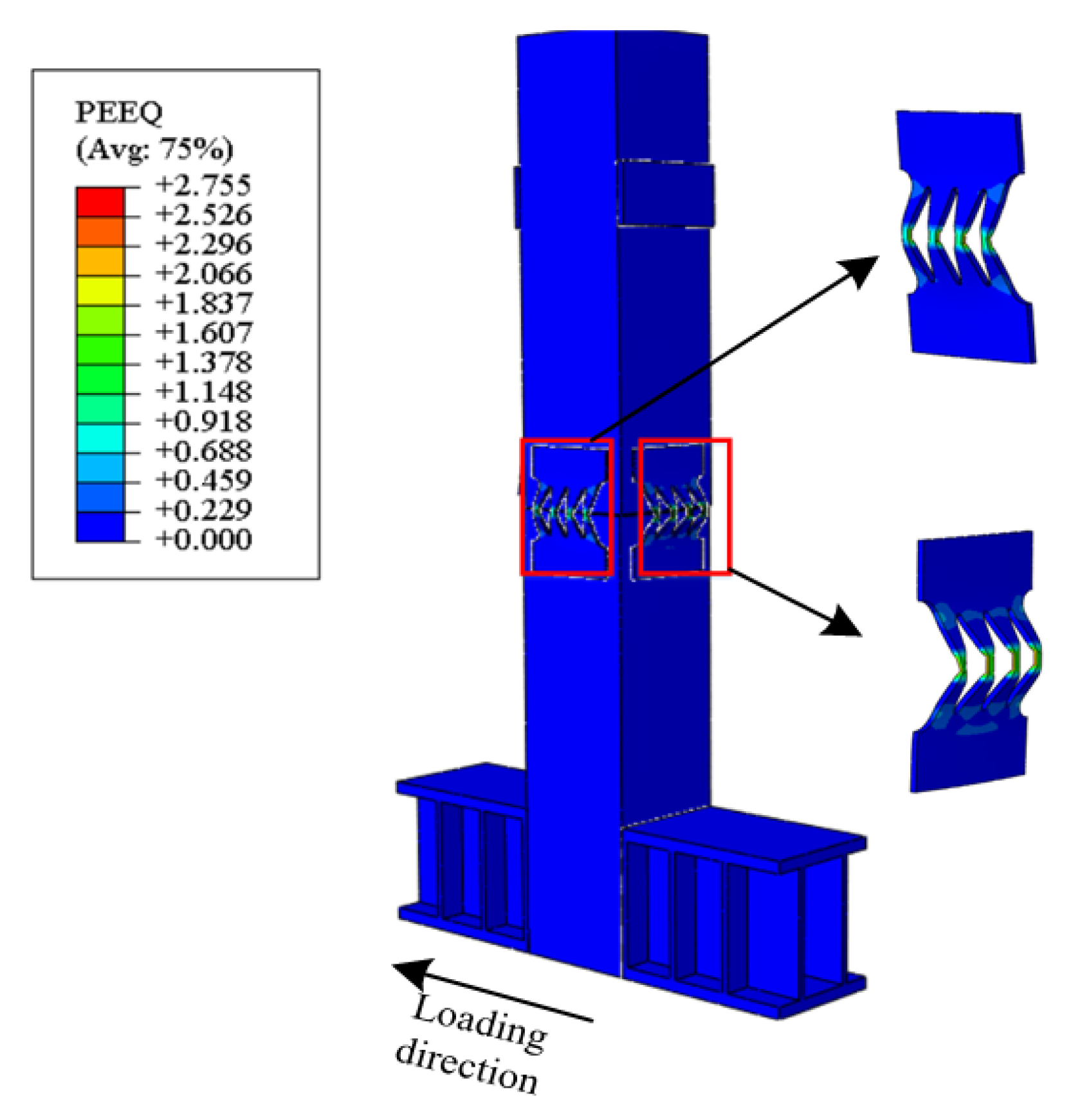
It can be seen from Figure 4 that the plastic strain of the CFST-R specimen is concentrated on the energy dissipation elements, which indicates that damage is concentrated here. The deformation and energy dissipation of the pier are mainly concentrated at the joints, and there will be no excessive joint opening and serious damage in the middle and upper part of the pier body. The energy dissipating element is only damaged in the middle part, and the joints at both ends are still in the elastic stage, which ensures that the energy dissipating element is easy to repair or replace after the earthquake.
3. Experimental Designing
3.1. Model Design
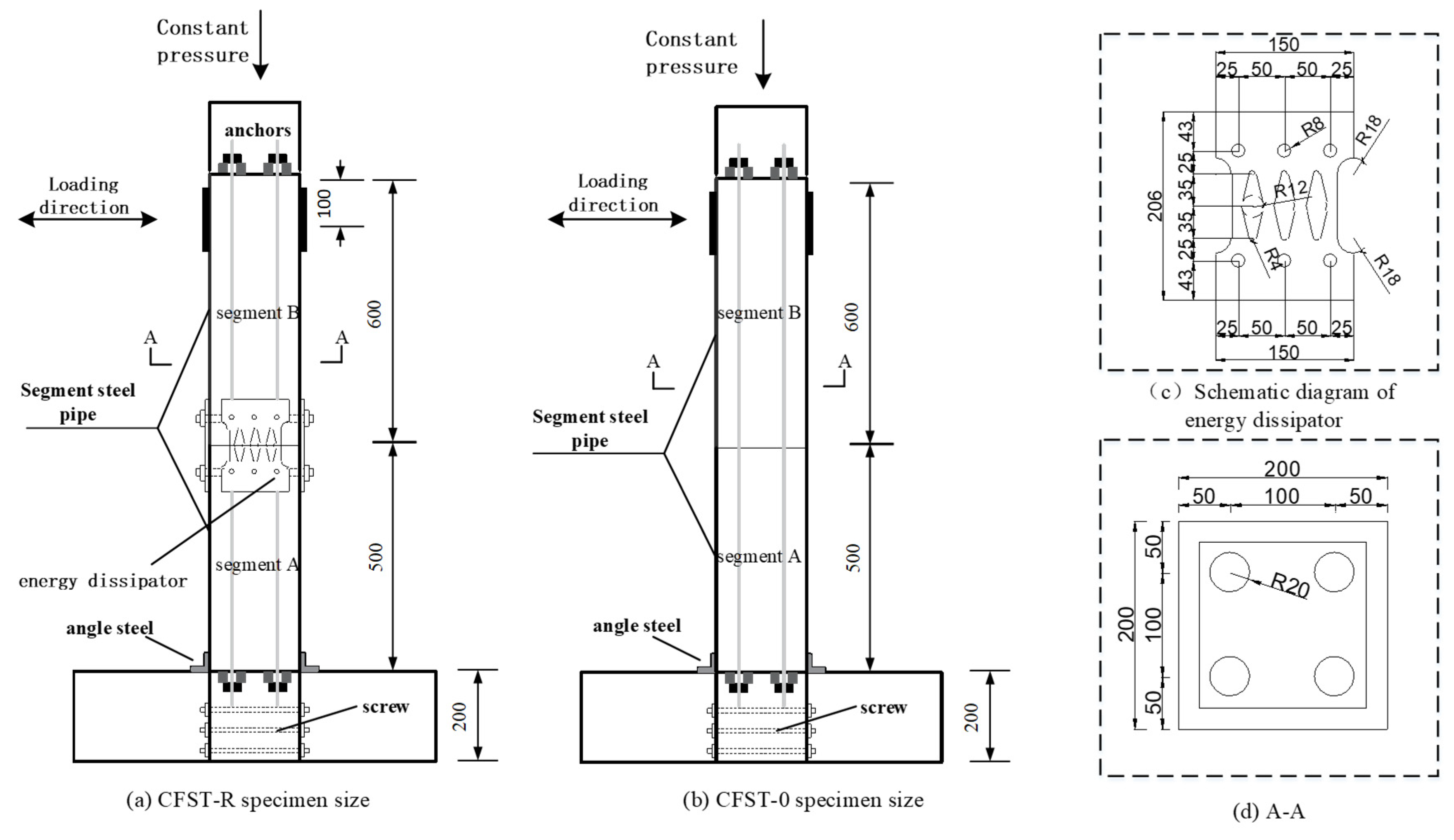
Two segmental assembled CFST pier model specimens were designed and processed, which are called CFST-0 (segment Assembled CFST pier) and CFST-R (CFST pier with external replaceable energy dissipator), as shown in Table 1 and Figure 5.
Q345 steel was used for the steel pipes of the two model test pieces. The outer diameter of the steel pipe was 200 mm, and the wall thickness was 20 mm. The height of sections A and B were 500 mm. In order to prevent stress concentration damage at the joint between segment A and the bearing platform, four rectangular angle steel sheets were welded at the joint between segment A and the bearing platform. The joints of CFST-R segments A and B were connected by external energy dissipators, which can be used as energy dissipation components and shear resistant. The energy dissipators were connected with CFST segments through embedded screws. Six embedded screws were arranged in each row, which were evenly arranged 60 mm away from the upper and lower ends of the segment. The diameter of the embedded screws was 20 mm. C40 concrete was poured inside the steel pipe. The energy dissipator between segments of CFST-R specimens was Q235 steel, 10 mm thickness. A rhombic hole was set in the middle of the energy dissipator, which gradually narrows from both ends to the middle. It avoids stress concentration damage at the screw hole and ensures that the weakest position is in the middle of the energy dissipation component.
As shown in Figure 5d, both CFST-R and CFST-0 reserve 40 mm diameter prestressed duct, which adopts unbonded post-tensioning prestress. The prestress was about 200 kN, the vertical load was constant at 180 kN, the axial compression ratio was 0.15, and the effective height of the pier was 1000 mm. Concrete was poured between the bottom of section A and the bearing platform and fixed through a screw connection.
3.2. Test Materials and Properties
The test pier was a concrete-filled steel tubular structure. For the mechanical properties of the test, materials have a great impact on the seismic performance of the pier; the compressive and tensile tests were carried out on the concrete and steel.
The compressive strength was obtained with an axial loading test according to the GB 50010-2010 [22] standard for test methods of physical and mechanical properties of concrete for each group, including three concrete test blocks (150 mm cubes). Then, we averaged the results as shown in Table 2. The elastic modulus of C40 concrete is .
The tensile properties of steel were tested according to the Chinese standard GB/T 228-2010 [26]. Each set of tests consisted of three tensile specimens, and the results were taken as the average. The yield strength and modulus of elasticity are listed in Table 3. Where represent yield strength, ultimate tensile stress, and elastic modulus of steel, respectively.
3.3. Test and Loading Scheme
The apparatus for the test was MTS, focusing on the non-linear relation of force and displacement, opening between segments, residual displacement of segments, and stiffness degradation.
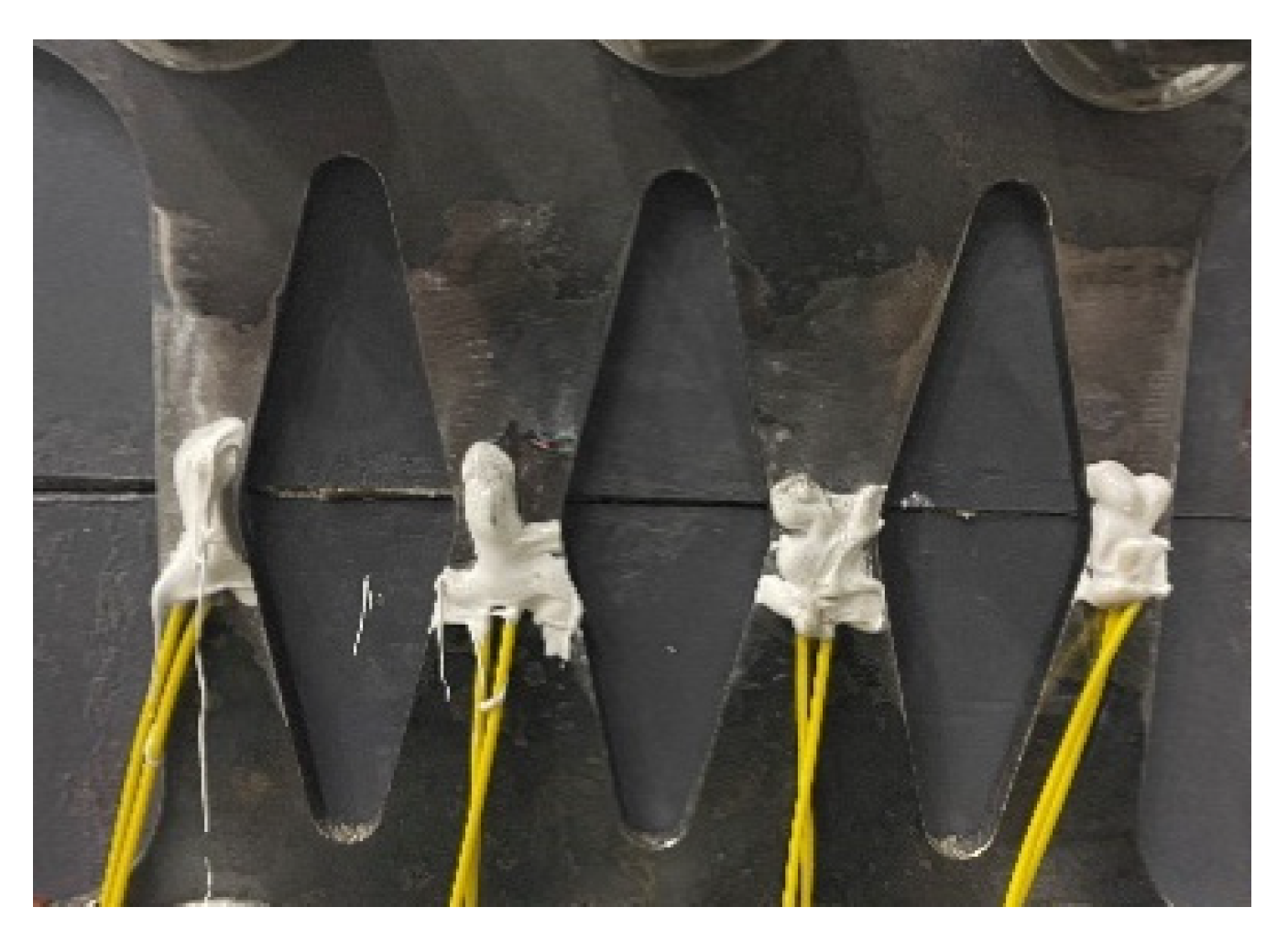
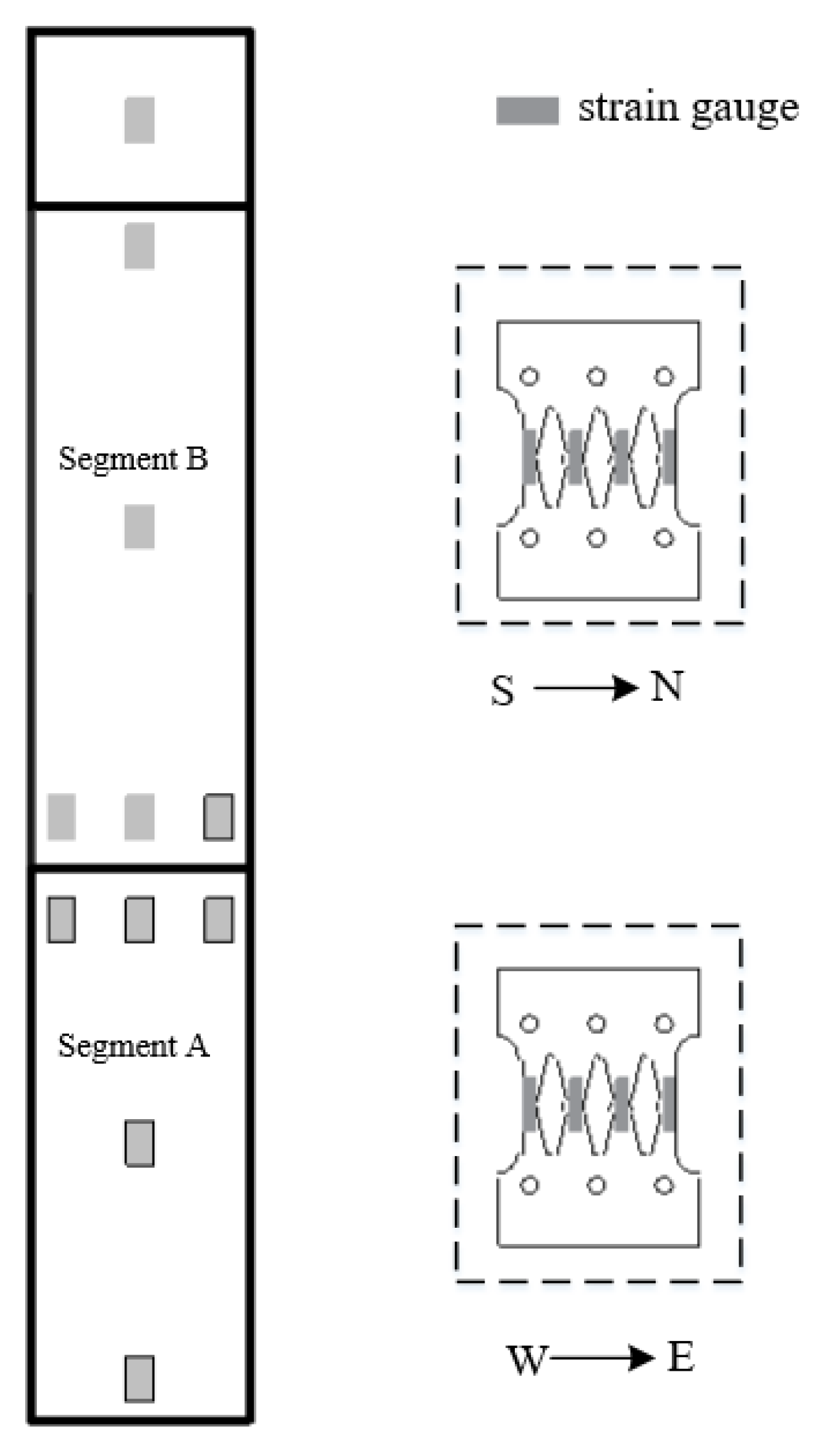
In order to monitor the stress state of segmental steel pipes and energy dissipators during horizontal reciprocating loading, longitudinal strain gauges were pasted on the upper, middle, and lower parts of each steel pipe, and strain gauges were pasted on the corners of the joints of segmental steel pipes. Longitudinal strain gauges were uniformly distributed at the left, middle, and right weak positions of the energy dissipator. The sticking method of the strain gauge on the energy dissipator is shown in Figure 6 and the arrangement of strain gauges is shown in Figure 7.
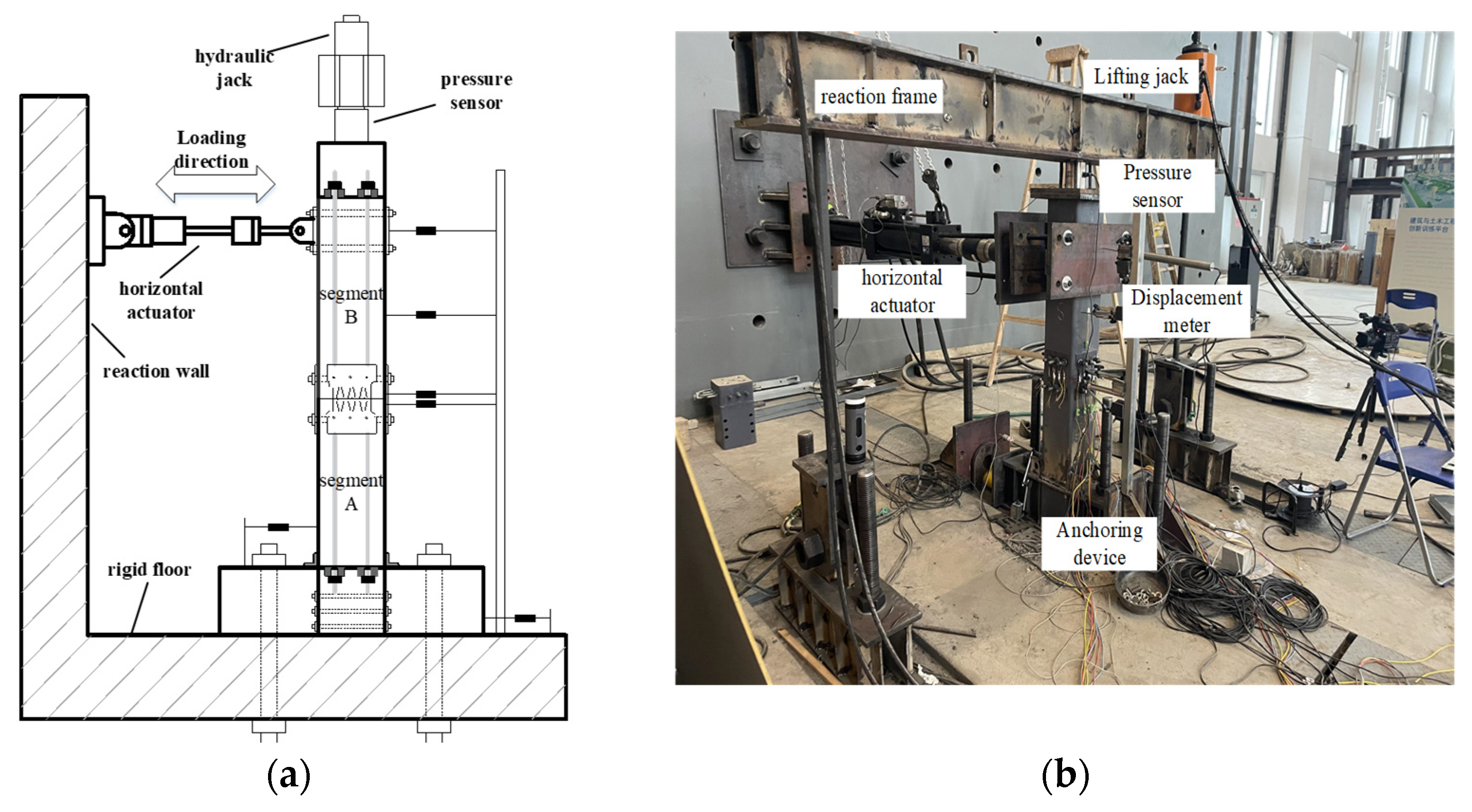
In the horizontal direction of the pier, the low cycle reciprocating loading was carried out through the electro-hydraulic servo actuator with a displacement stroke of ±250 mm and specification of 25 t. One end of the actuator was fixed on the reaction wall, and the other end was connected with the CFST pier segment B through the steel plate and screw. In the connection process, we ensured that the center of the actuator steel plate was aligned with segment B.
The axial force on the pier top was applied by the lifting jack, and the force was transmitted to the top of the CFST pier through the reaction frame. The axial force always remained around 180 kN. The value on the table of the oil pump was controlled by adjusting the oil valve to ensure that the variation range of the axial pressure was lower than 5%. In order to prevent relative sliding between the bearing platform and the ground during reciprocating loading, ground beams were installed on both sides of the bearing platform and anchored with the ground through ground anchors. At the same time, a small jack was butted on both sides along the loading direction to ensure that the cushion cap was firmly anchored to the ground. The quasi-static loading device is shown in Figure 8.
The layout of the displacement meter is shown in Figure 8a. A displacement meter was set between the bottom bearing platform and the floor to monitor whether the CFST pier specimen had a horizontal offset rate.
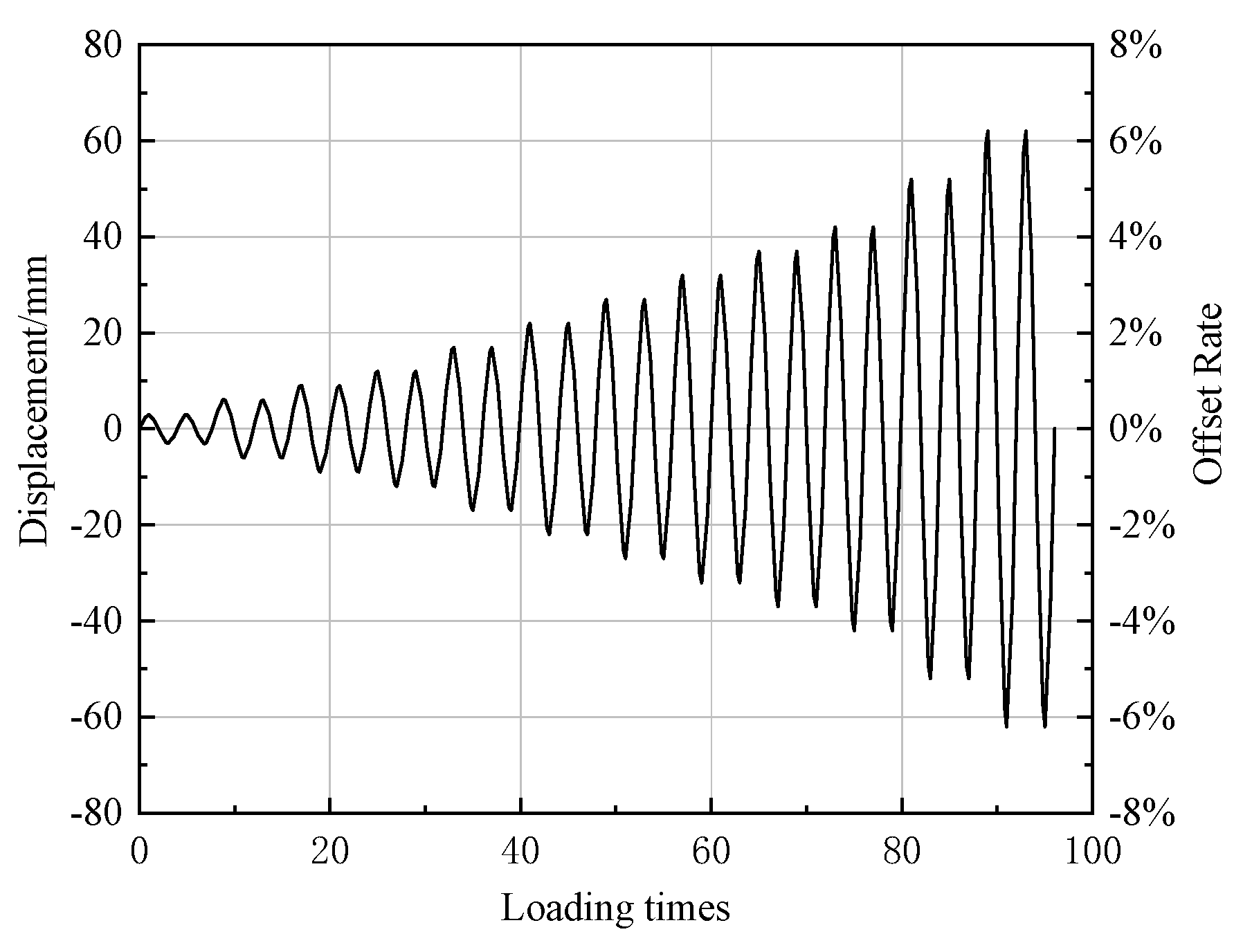
Test loading system: displacement-controlling loading, as shown in Figure 9. The displacement to be loaded was 3 mm, 6 mm, 9 mm, 12 mm, 17 mm, 22 mm, 27 mm, 32 mm, 37 mm, 42 mm, 52 mm, and 62 mm in turn. The loading was stopped until the bearing capacity of the specimen was reduced to 85% of the maximum horizontal load or the core concrete was crushed.
4. Analysis of Test Phenomena and Results
4.1. Analysis of Test Phenomena
4.1.1. CFST-0
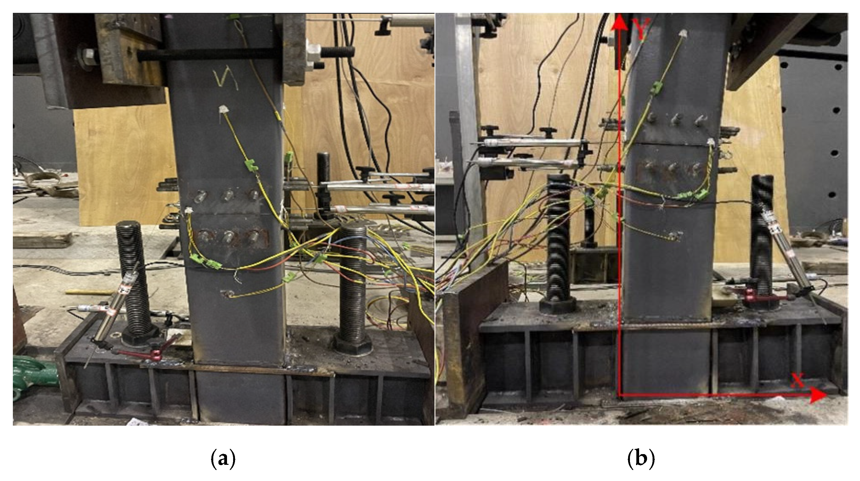
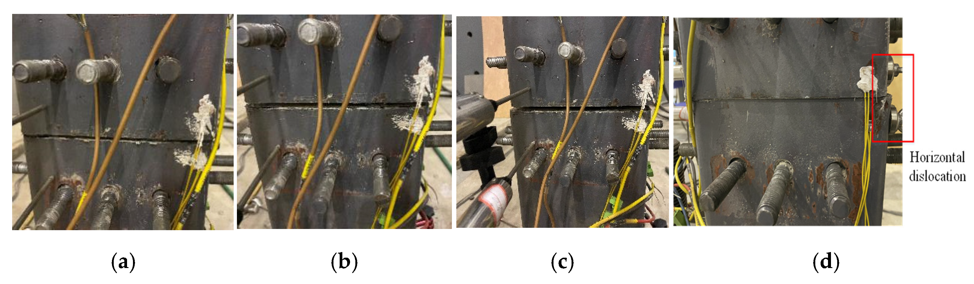
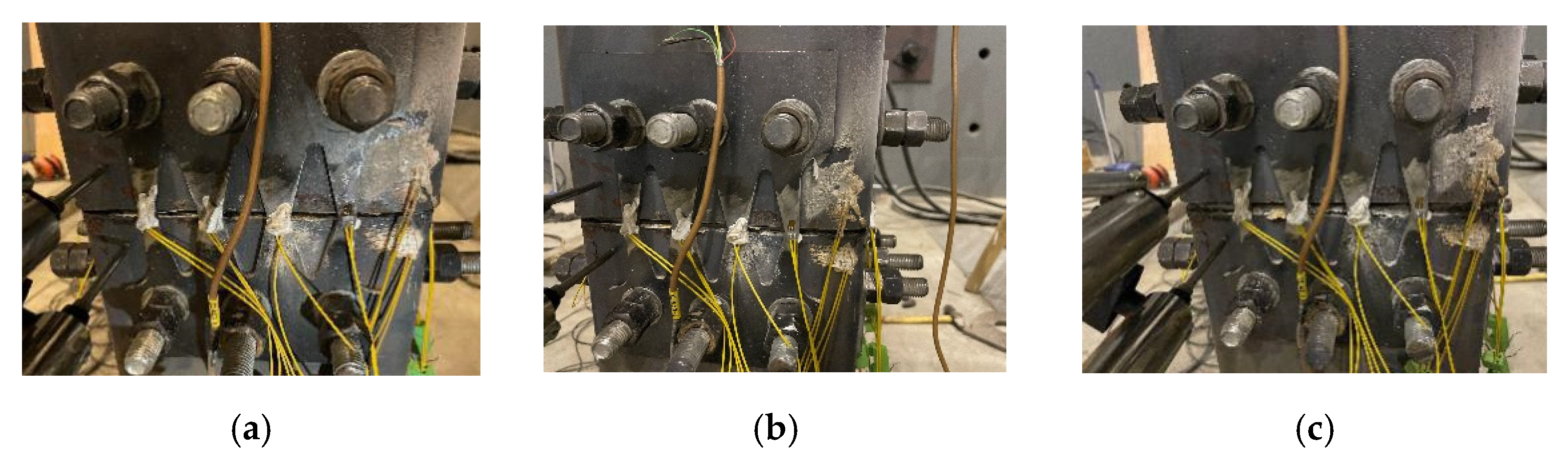
Figure 10 compares the pier shape of the CFST-0 specimen before loading and when its lateral displacement reaches the maximum. During the test, the pier body swings left and right with the change of horizontal displacement. There was no significant displacement or damage in the joint or the pier body when the displacement of the pier top was lower than 22 mm (offset rate 2.2%). When the displacement reached 22 mm (offset rate 2.2%), there was an opening at the joint between segments B and A; segment B squeezed into the steel pipe of segment A, as shown in Figure 11a. When the displacement reached 32 mm (offset rate 3.2%), segment B continued to squeeze the steel pipe of segment A, and the opening on the other side became larger, as shown in Figure 11b. When the displacement reached 42 mm (offset rate 4.2%), there was an obvious opening between segments A and B, and there was an obvious horizontal dislocation between segments A and B, as shown in Figure 11c. The test should be ended for safety due to the large horizontal displacement at the joint. After loading, the pier body of the concrete-filled steel tubular section had no obvious deformation or damage; however, the horizontal dislocation remained.
4.1.2. CFST-R
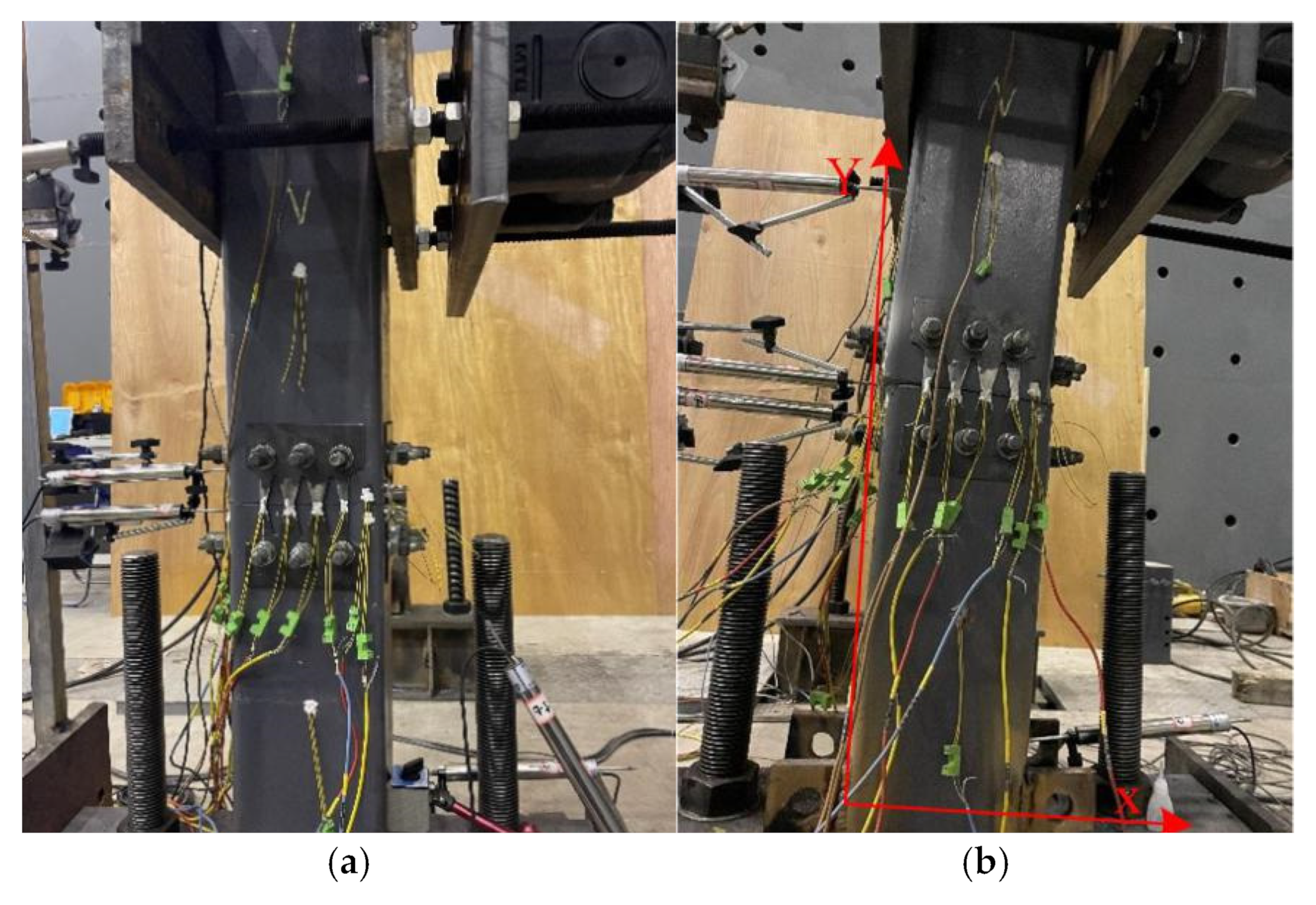
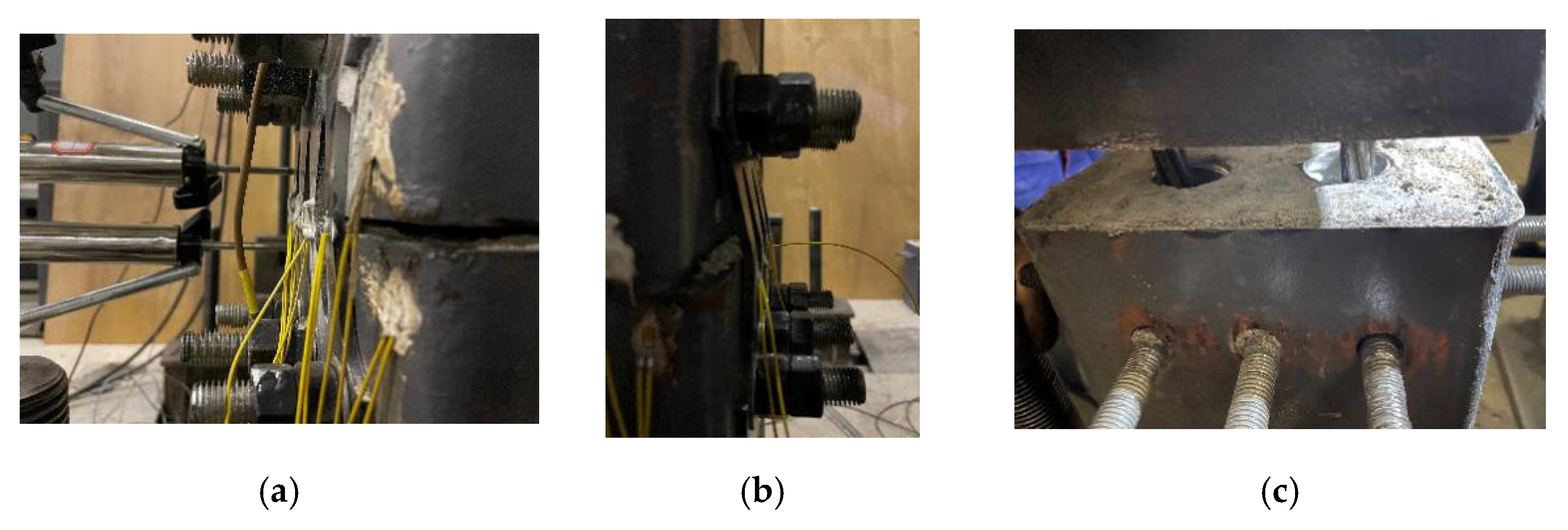
Figure 12 compares the pier shape of CFST-R before loading and when loading to the maximum lateral displacement. During the test, the pier body of the test piece swung left and right with the change of lateral displacement. In the early stage of loading, before the loading displacement reached 22 mm (offset rate 2.2%), there was no obvious deformation and damage in the pier body, joint position, or energy dissipation elements. When the loading displacement reached 22 mm (offset rate 2.2%), a slight opening angle began to appear at the joint between segment A and segment B. At this time, the energy dissipation element in the segment joint was stretched to dissipate energy. When the displacement reached 42 mm (offset rate 4.2%), the opening between segments A and B increased, and the elongation of energy dissipation elements increased. When the lateral loading reached the negative maximum value of the corresponding loading grade, there was obvious bending deformation, and the energy dissipation elements reached yield. With the increase in loading displacement, the opening of the joint between segments A and B increased, and the deformation of the energy dissipation element also increased. The deformation was concentrated in the weak part in the middle of the energy dissipation element, and there was no large deformation at the screw and screw hole.
The deflection rate of the test piece reached 6.2% and exceeded 5%, and the energy dissipation element yielded. In order to carry out the subsequent test of replacing the energy dissipator, the test was stopped.
After loading, there was no obvious damage to the pier body. Different from the CFST-0 specimen, the opening of the joint between segments A and B was small as shown in Figure 13, and the steel pipe at the edge of the joint was slightly warped after loading. The damage to the pier could be considered to be concentrated on the energy dissipation elements set at the joint, and the nuts and screw holes were well connected without obvious plastic deformation. The damage of the energy dissipation elements was concentrated in the weak position in the middle as shown in Figure 14b. The concrete was not crushed as shown in Figure 14c, which made it easy for disassembly and replacement after loading.
4.2. Analysis of Test Results
4.2.1. Hysteretic Characteristics
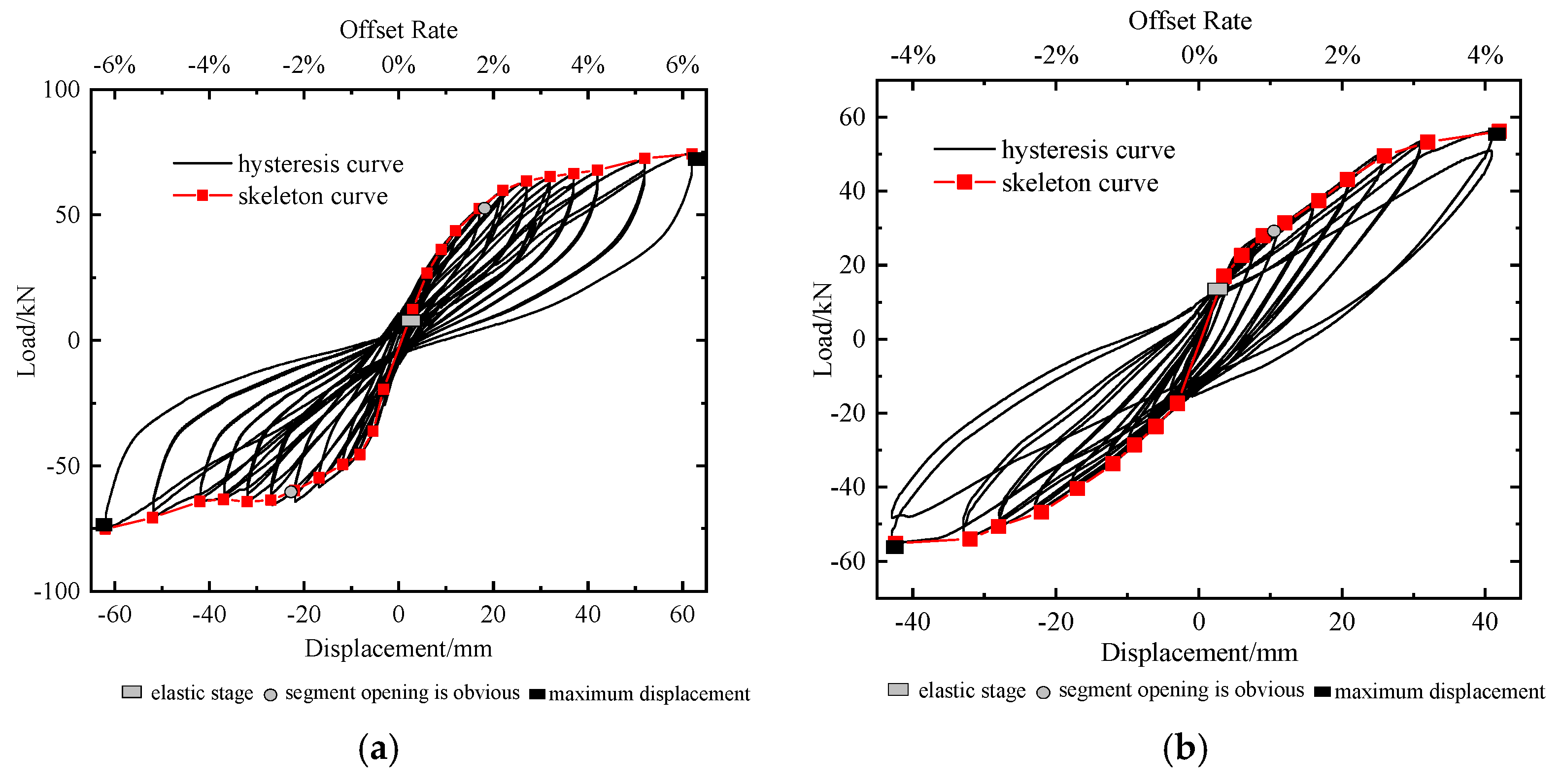
Figure 15 shows the mechanical behavior of CFST-R and CFST-0 under reciprocating loading. It can be seen that the hysteretic curves of the two specimens are similar to the shuttle shape. The hysteretic curve of CFST-R is relatively pinched, the energy consumption capacity is poor, and the lateral bearing capacity is low. However, the residual displacement is very small, indicating that the pier has a strong self-resetting ability under prestressed traction. The hysteretic curve of the CFST-R specimen with energy dissipation elements is fuller.
Compared with the CFST-0 specimen, the energy dissipation capacity of CFST-R is stronger, and the ultimate bearing capacity is improved. It means that the setting of this new energy dissipator can improve the hysteretic performance of the segmental assembled CFST pier. Compared with the CFST-0 specimen, however, the residual displacement of the pier with energy dissipator increases slightly. According to the standard, the residual deformation of the CFST-R specimen is still repairable after an earthquake, as the residual displacement is lower than 1%, which shows that the energy dissipator makes the pier easily repairable, although the deformation recovery capacity is relatively weak.
The skeleton curves of the CFST-R and CFST-0 specimens can be seen in Figure 15. For the CFST-R specimen, when there is an opening (offset rate 2.2%) between segment B and segment A, the stiffness of the specimen decreases, and the increased speed of the horizontal load slows down and enters the non-linear increase stage. As the energy dissipation element enters the plastic stage, the horizontal load reaches its peak for the first time. Due to the influence of the P–∆ effect, when the initial peak value of the horizontal load is reached, the horizontal load basically does not change with the increase of the pier top displacement, and the skeleton curve enters the platform stage. However, as the energy dissipation element enters the strengthening stage, with the increase of the pier top displacement, secondary stiffness appears, and the bearing capacity increases significantly.
In the early elastic recovery stage (the offset rate is about 1%), the skeleton curves of the two specimens are close to a straight line. Due to the energy dissipator set in CFST-R, the pier has higher initial stiffness than CFST-0. With the increase of lateral displacement, the specimen rotates rigidly in the joint area, the plastic deformation increases, the pier enters the elastic-plastic stage, and the stiffness decreases gradually. With the continuous loading, the energy dissipating elements deform and dissipate energy, and the lateral bearing capacity of the CFST-R specimen also increases gradually. When the lateral displacement reaches 62 mm (offset rate 6.2%), the lateral bearing capacity of the CFST-R specimen increases significantly and reaches the limit value of 74.26 kN. Compared with the 50.16 kN of the CFST-0 test piece, it increased by 48%. This is mainly due to the traction effect of the added energy dissipation element, which improves the overall lateral strength of the pier.
4.2.2. Stiffness Degradation Law
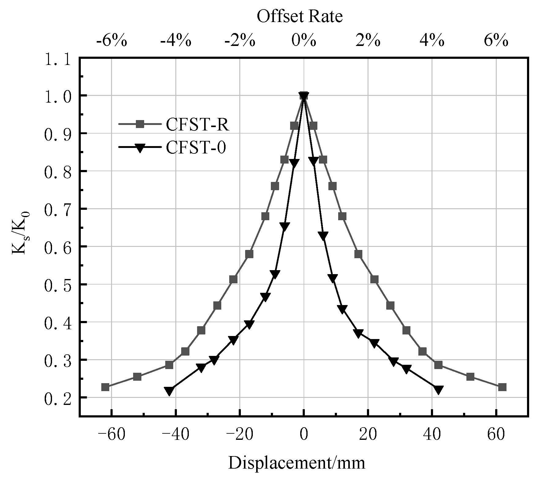
The stiffness of the pier is usually expressed by equivalent stiffness or the ratio of equivalent stiffness to initial stiffness. The equivalent stiffness constantly changes with lateral displacement, which describes the stiffness degradation law of the pier. Where initial stiffness is the tangent slope of the load-displacement curve at the origin, which reflects the stiffness of the pier in the initial stage of elasticity. Equivalent stiffness is defined as the slope of the connecting line between any point of the load-displacement curve and the origin, except the origin, which reflects the stiffness change of the pier during the whole loading process. The equivalent stiffness calculation formula is as follows:
In order to understand the stiffness degradation of the two specimens, the initial stiffness and equivalent stiffness of the specimens under each loading level are extracted. The curve of the lateral displacement amplitude is shown in Figure 16.
As shown in Figure 16, the stiffness of the CFST-R and CFST-0 specimens decreases greatly in the initial elastic stage. In the early stage of loading, the stiffness degradation rate of the CFST-0 specimens without energy dissipation members is faster. When reaching the lateral displacement amplitude, the equivalent stiffness of the CFST-R specimen decreases to 22.75% of the initial stiffness; the CFST-0 specimen decreases to 21.94% of the initial stiffness. During the loading process, the stiffness of CFST-R and CFST-0 decreases gradually due to the continuous opening of joints between segments and the continuous accumulation of plastic deformation. In conclusion, the setting of energy dissipators can slow down the stiffness degradation rate of segmental assembled CFST piers.
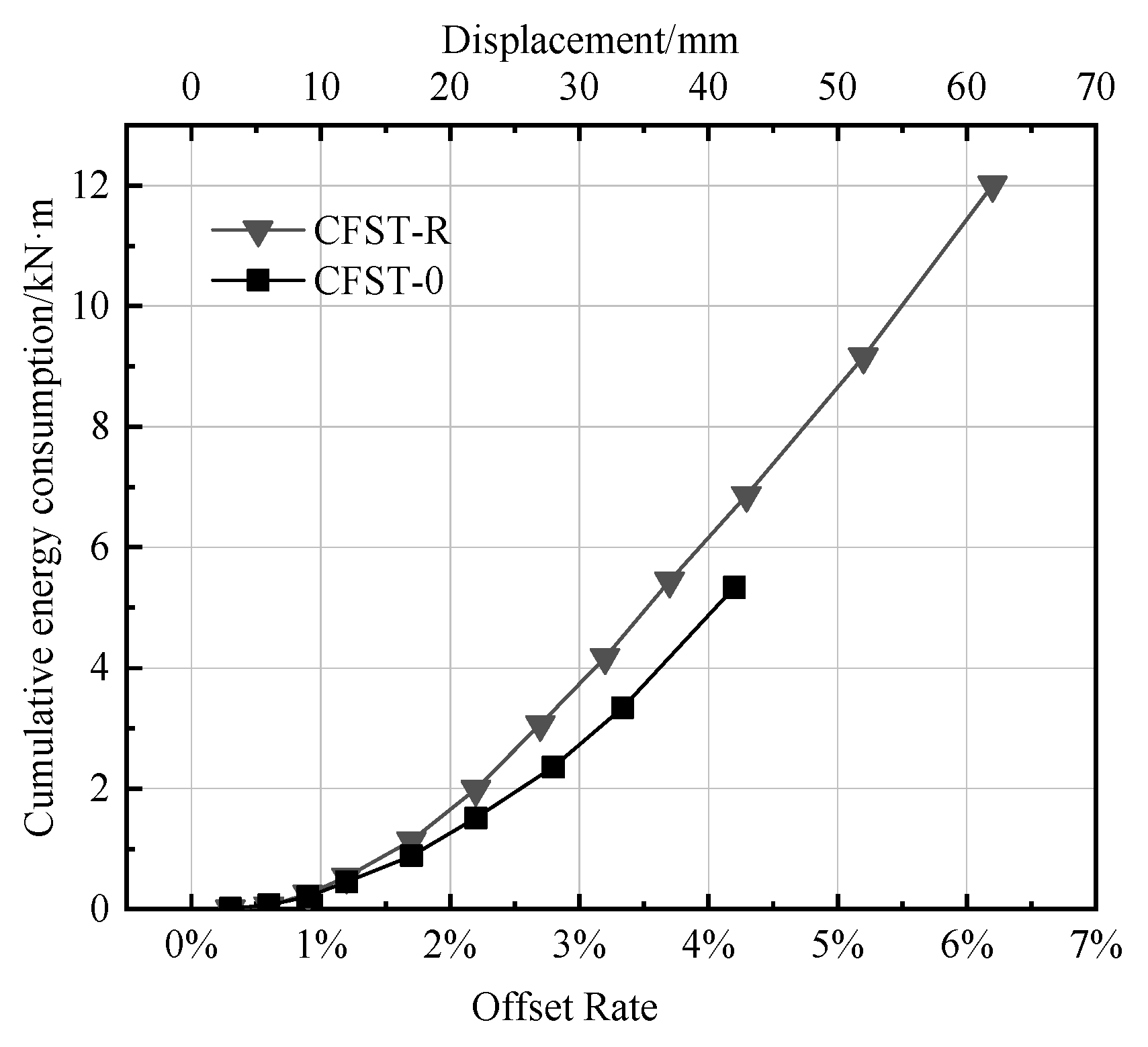
4.2.3. Cumulative Energy Consumption Capacity
The pier dissipates energy by absorbing and resisting the seismic force in the process of deformation. Energy dissipation capacity is often calibrated by the cumulative energy dissipation value and equivalent viscous damping ratio, where the cumulative energy consumption value is defined as the sum of the area enveloped by the load-displacement curve under each loading level. Generally speaking, the greater its value, the better the seismic energy dissipation capacity and seismic performance of the pier. The cumulative energy consumption curve of the first cyclic loading of the finishing specimen is shown in Figure 17.
It can be seen from Figure 17 that the energy dissipation capacity of the CFST-0 specimen without additional energy dissipation members is poor, while the cumulative energy dissipation capacity of the CFST-R specimen is significantly improved due to the existence of energy dissipators. When the lateral displacement reaches 37 mm (offset rate 3.7%), the cumulative energy dissipation values of the two specimens are 6.8 kN·m and 5.74 kN·m, respectively. It can be concluded that the setting of energy dissipators can effectively improve the energy dissipation capacity of segmental assembled CFST piers.
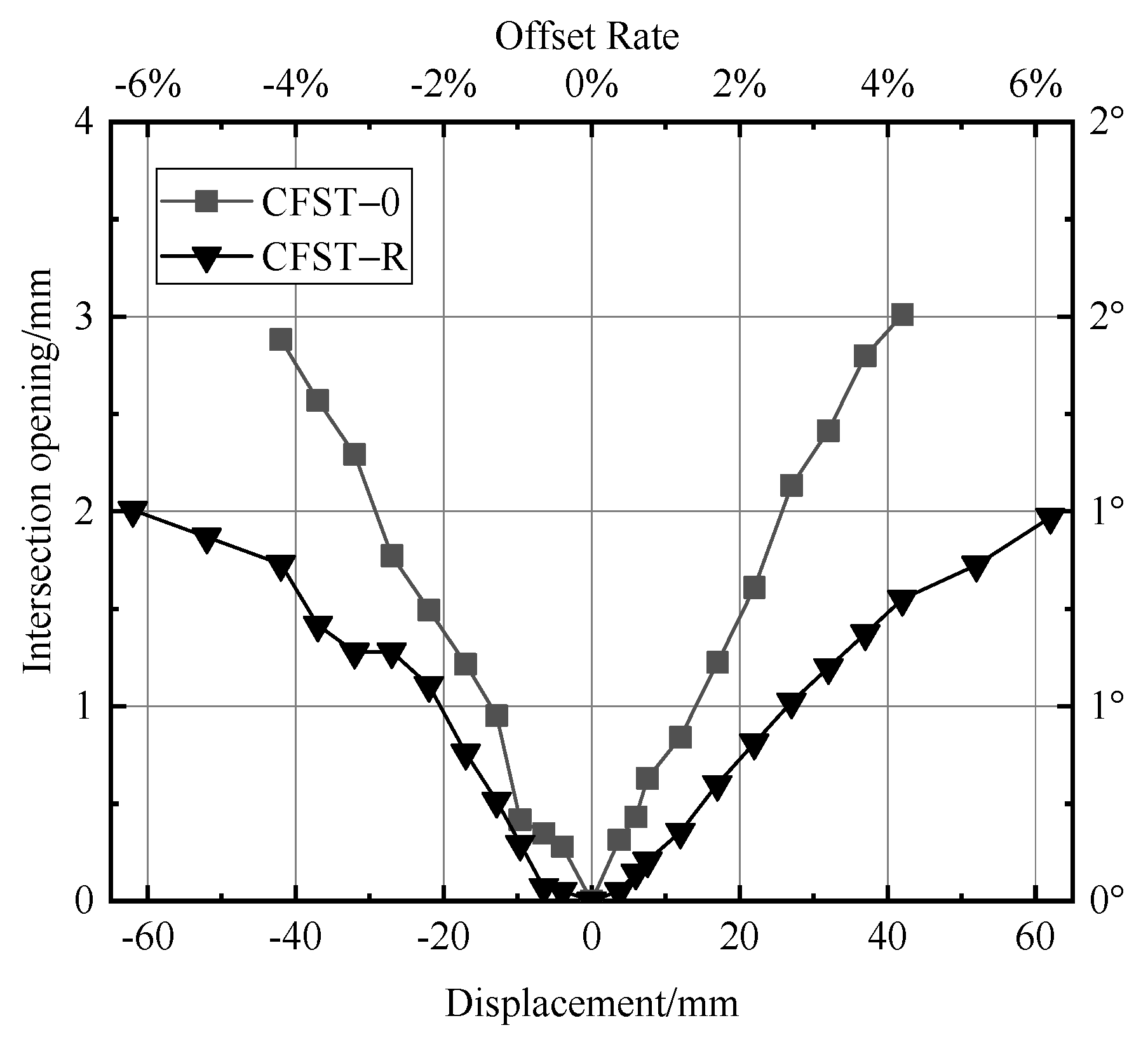
4.2.4. Opening at the Seam
The opening between segments is also an important index for the fabricated segment assembled pier. Normally, opening a joint is common if the fabricated segment assembled pier has dry joints.
In order to study the connection between segments of the segmental assembled pier, the test focused on segments A and B, and the opening of the two specimens is shown in Figure 18. Through the opening between segments, it can be seen that:
- (1)
- Because the energy dissipation elements are arranged at the joint of the CFST-R specimen, compared with the CFST-0 specimen, the opening between segments can be effectively restrained. It can be seen that when the displacement is 42 mm (offset rate 4.2%), the opening amount of the CFST-0 specimen is 2.88 mm, and that of the CFST-0 specimen is 1.73 mm.
- (2)
- It can be seen from Figure 15 that the rate of the opening amount increases at first and then slows down with the increased offset rate. The change in the rate of opening reflects the size of the horizontal load.
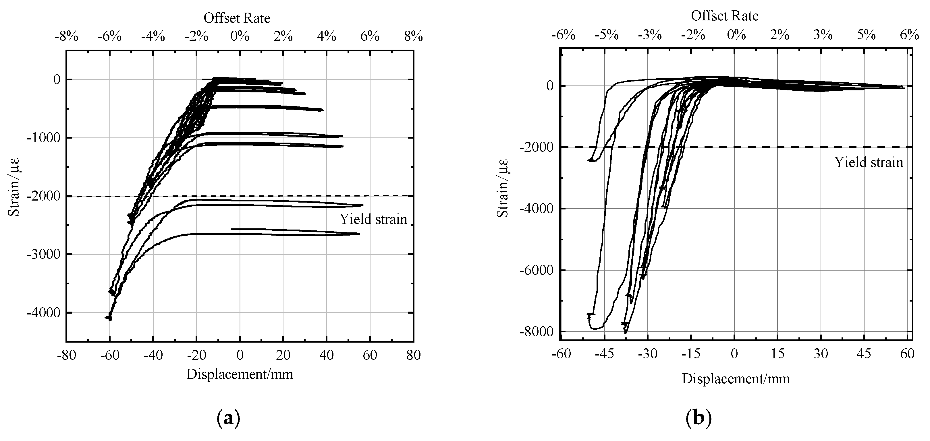
4.2.5. Strain of Steel Pipe and Energy Dissipation Element
Since the appearance of concrete-filled steel tubular segments is not obviously damaged during the test, strain measurement is an important basis for analyzing the stress state of steel tubular materials. Due to the limited space of the test, only the stress-strain analysis and summary of key positions are discussed below.
Figure 19 shows the strain of the segment A steel pipe at the joint of the CFST pier. It can be seen from the figure that the CFST-R steel pipe section yielded after the displacement reached 42 mm, while the CFST-0 steel pipe section yielded when the displacement reached about 17 mm. When the displacement of CFST-R reached 62 mm, the strain value was 4000 . When the displacement of CFST-0 reached 42 mm, the strain of the steel pipe was 8000 .
The results show that the external energy dissipation element can effectively reduce the damage to the steel pipe itself and prevent the steel pipe section from yielding prematurely when the displacement is small.
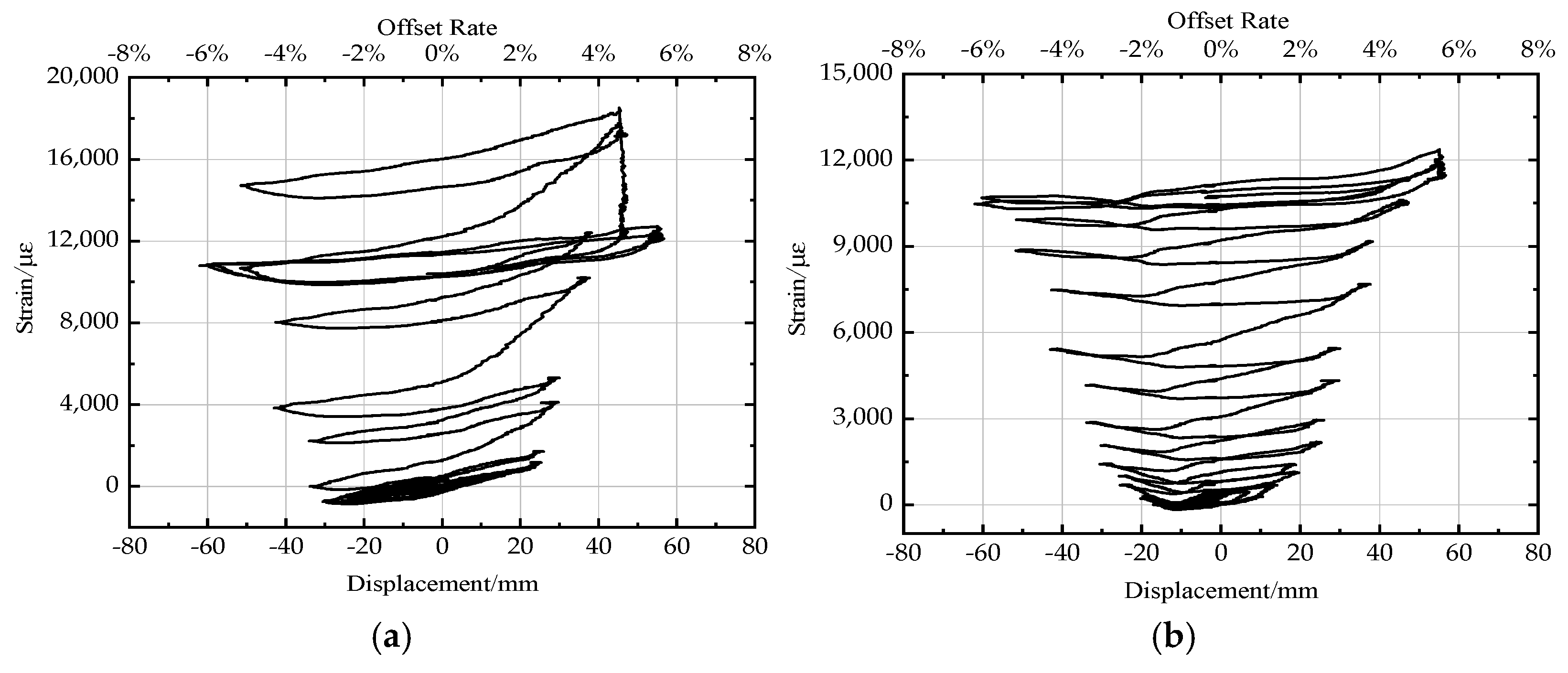
Figure 20 shows the strain diagram of energy dissipation elements on the east and west sides of the CFST-R specimen. It can be seen from the figure that the strain of the east side energy-dissipating element reached about 20,000 με when the displacement reached 62 mm (offset rate of 6.2%), which is far greater than the strain value of the steel pipe section. It shows that the external energy dissipation element can concentrate the damage on the energy dissipation element. It can reduce the deformation and damage of the steel pipe section. Figure 20b shows the strain of the energy dissipation element on the west side. When the displacement reached 62 mm (offset rate 6.2%), the strain value was about 13,000 . It was smaller than the energy dissipation element on the east side, which may stagger to the east during the test loading so that the energy dissipation element on the east side bears part of the shear force. At the same time, however, the strain of the west energy dissipation element was much larger than that of the steel pipe section 4000 . This phenomenon verifies that the arrangement of energy dissipation elements can concentrate the damage, which reduces the damage and deformation of steel pipe segments.
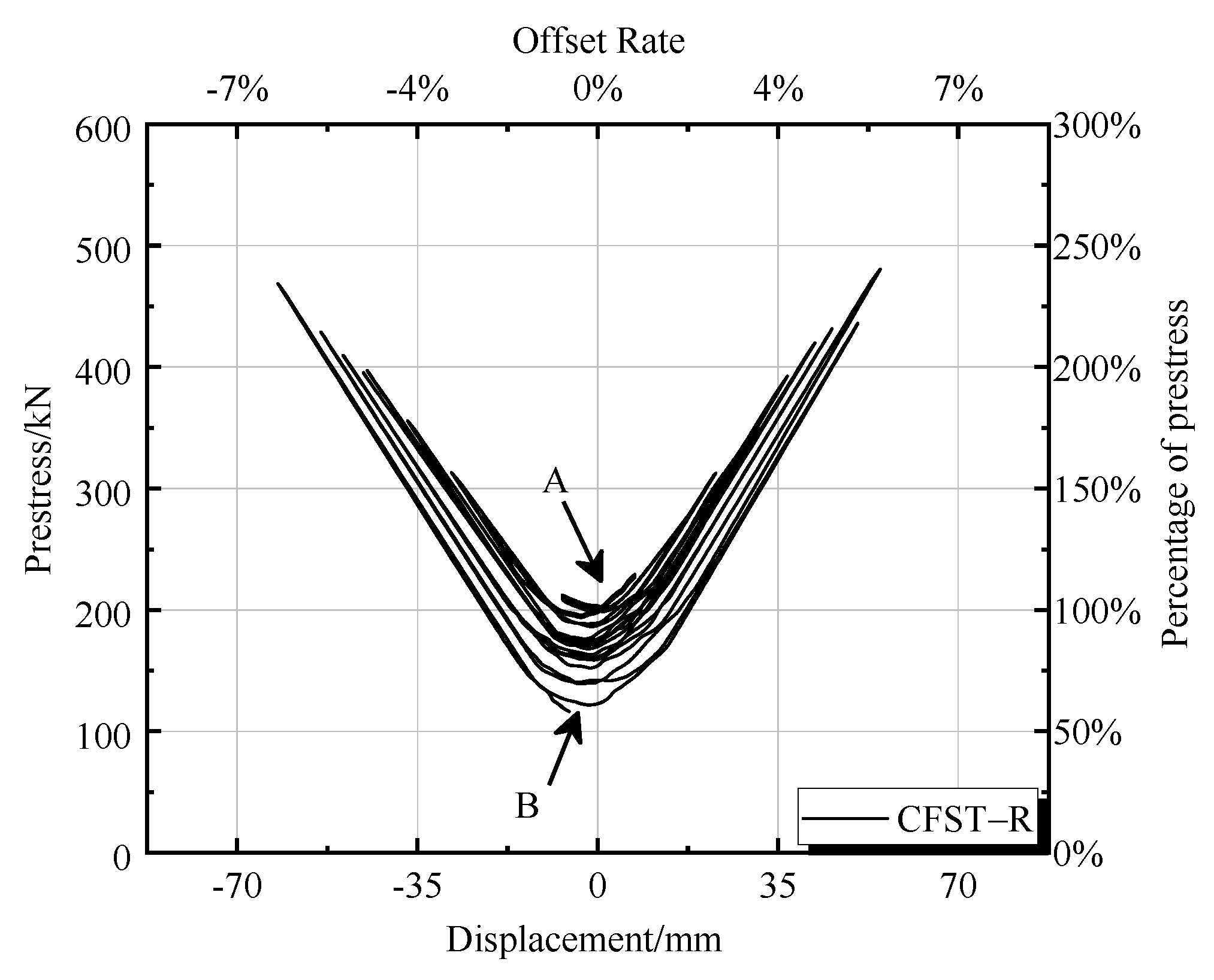
4.2.6. Prestress Change
In the process of horizontal reciprocating loading, the prestressed tendon of the CFST-R specimen will elongate or shorten with the change of loading displacement, resulting in the change of prestress. As shown in Figure 21, the initial prestress value at point A was 200 kN. When loaded to the maximum displacement (offset rate 6.2%), the prestress value was 482 kN, which is 241% of the initial tension before horizontal loading. At this time, the stress of the prestressed tendon was 854 MPa, and the prestressed tendon was still in the elastic stage and did not yield. It can be seen from Figure 18 that when each stage of loading returns to the initial position, there is a corresponding loss of prestress.
After the pier top reached 62 mm, the maximum horizontal displacement (offset rate 6.2%) and unloading were complete, the tensile force in the prestressed reinforcement decreased to 70% of the previous value (140 kN), and the prestress loss was 30%. The prestress loss was mainly caused by the deformation of the anchorage and the friction between the steel strand and the pipe wall of the prestressed hole.
Under the reciprocating horizontal load, the tensioning force in the prestressed reinforcement changes with the horizontal displacement of the pier top and may produce large prestress loss. The factors affecting the prestress loss are still worthy of in-depth consideration.
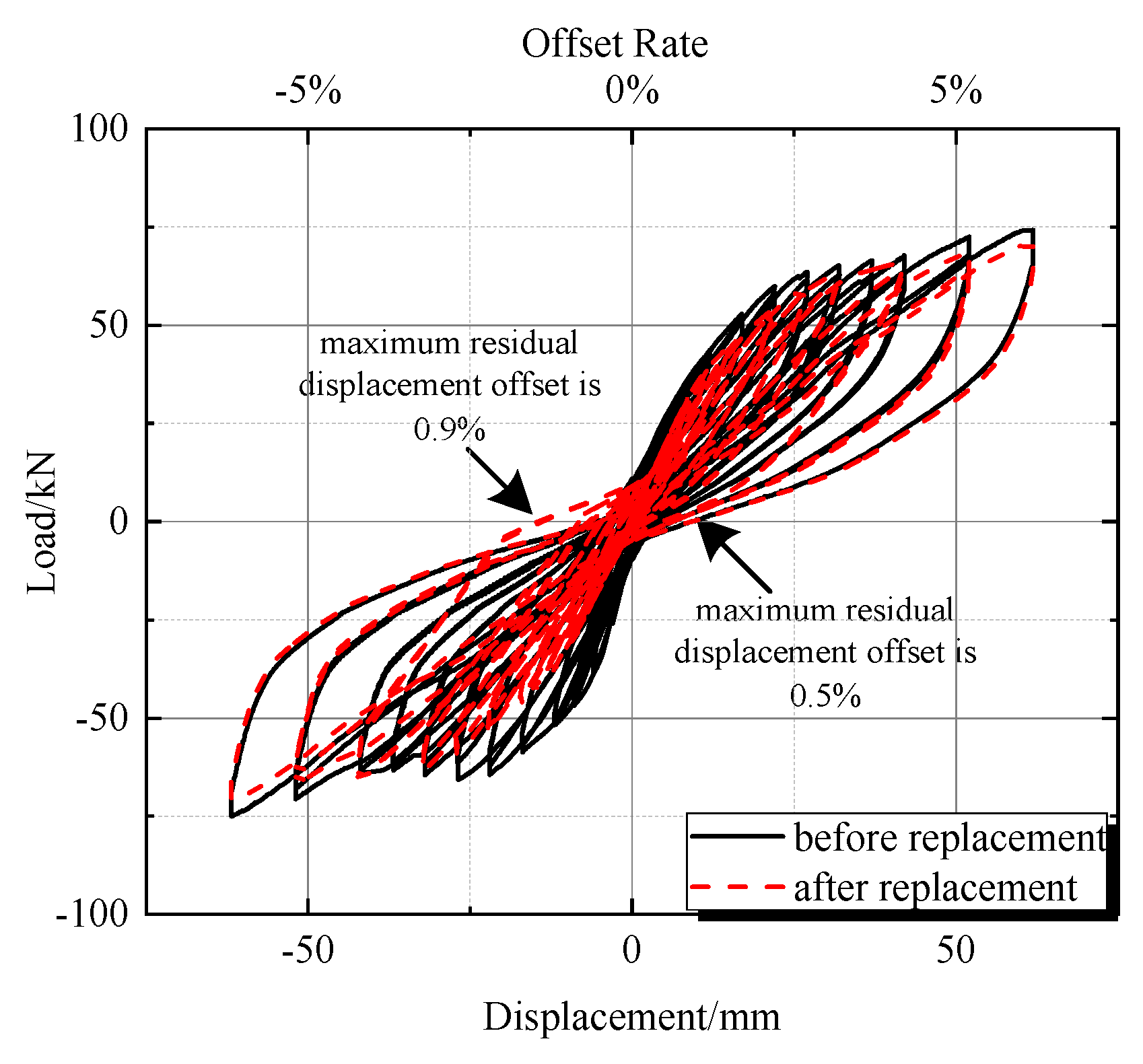
4.2.7. Replace the Energy-Consuming Device
The energy dissipation elements fixed on the CFST pier were removed after the previous test. Another group of the same energy dissipation elements was fixed at the joint of the steel pipe section through bolts, realizing the replacement of the energy dissipator. Then, the CFST pier after replacement was subjected to the same low-cycle displacement loading, and the results were analyzed. Figure 22 compares the hysteretic curve of the CFST pier before and after replacing the energy dissipator.
It can be seen from Figure 22 that the hysteretic curves of the model before and after replacement are basically the same, and both curves are relatively full. The maximum lateral bearing capacity of the test piece of the bridge pier before replacement was 74.05 kN, and the maximum lateral bearing capacity of the test piece of the bridge pier after replacement was 68.95 kN, which was reduced by 6.8%. The maximum residual displacement deviation rate of the CFST pier specimens before replacement was 0.5%, and the maximum displacement deviation rate of the CFST pier specimens after replacement reached 0.9%, which is slightly higher than before replacement. However, the maximum displacement deviation rate is still at a low level, which reflects that the CFST pier has a good self-resetting ability. After the test of the first group of energy dissipation elements, the deviation of pier specimens was not corrected. Therefore, it can be judged that the replacement of the external energy dissipator has basically no impact on the seismic performance of the CFST pier.
5. Conclusions
- (1)
- Under a reciprocating load, the concrete-filled steel tubular pier shows good resistance to deformation, and the pier body has no obvious damage. Setting a replaceable external energy dissipator can reduce the opening size of joints between segments, which ensures the damage to the pier is concentrated on the energy dissipator, which is convenient for rapid disassembly and replacement.
- (2)
- From the test and finite element results, it can be seen that the hysteretic curve of the segmental assembled CFST pier without an energy dissipator is relatively pinched, the overall energy dissipation capacity deviation, and the lateral bearing capacity is low. Setting the energy dissipator can significantly improve the hysteretic energy consumption, lateral strength, stiffness, and other seismic performances of the segmental assembled CFST pier and also reduce the deformation recovery capacity of the pier. However, the pier should have a good self-resetting capacity which ensures the pier is repairable after an earthquake.
- (3)
- With the increase of horizontal loading displacement, the tensioning force of the prestressed tendon increases linearly, and there is a certain prestress loss in each stage of cyclic loading. After the pier top reaches 62 mm, the maximum horizontal displacement with an offset rate of 6.2%, and complete unloading, the prestress loss is 30%. The prestress loss in the fabricated assembled pier of the post-tensioned unbonded prestressed connection is significant, which should be emphasized.
- (4)
- The replacement of external energy dissipators will not affect the seismic performance of segmental assembled CFST piers.
- (5)
- The energy dissipator proposed in this paper is simple in structure and easy to replace. Based on the test and finite element analysis, the use of unbonded prestressed tendons with external energy dissipators can not only improve the energy dissipation capacity of CFST piers, but also ensure a small residual displacement, achieving the effects of self-resetting and stiffness. It provides research ideas and directions for the promotion of segmental assembled piers in medium- and high-intensity areas.
Author Contributions
The innovation of the article and the idea of writing the first draft were proposed by C.W.; Y.S. provided many suggestions and helped revise the paper; Z.Q. carried out the experimental design and data analysis of the paper and substantially contributed to writing and revising the paper; Y.S., B.P. and J.X. provided substantial help in preparing relevant data, finite element analysis, and the contents of the paper in the early stages. All authors have read and agreed to the published version of the manuscript.
Funding
This research was funded by Center for Balance Architecture, Zhejiang University.
Institutional Review Board Statement
Not applicable.
Informed Consent Statement
Informed consent was obtained from all subjects involved in the study.
Data Availability Statement
All data, models, or codes that support the findings of this study are available from the corresponding author upon reasonable request.
Conflicts of Interest
The authors declare no conflict of interest.
References
- Lan, H. Status of research on seismic performance of prefabricated segmental assembled bridge piers. Highw. Traffic Technol. 2012, 6, 38–42. [Google Scholar]
- He, S. Research on the Seismic Performance of Dry Jointed Unbonded Prestressed Segmental Assembled Piers. Bachelor’s Thesis, Xi’an University of Architecture and Technology, Xi’an, China, 2019. [Google Scholar]
- Han, L.; Yang, Y. Modern Concrete Filled Steel Tubular Technology; China Construction Industry Press: Beijing, China, 2007. [Google Scholar]
- Taira, Y.; Kasuga, A.; Unjo, S.; Asai, H. A Study on Restorable Precast and Prestressed Hybrid Piers; Multidisciplinary Center for Earthquake Engineering Research: Buffalo, NY, USA, 2009. [Google Scholar]
- Chou, C.C.; Chen, Y.C. Cyclic tests of post-tensioned precast CFT segmental bridge columns with unbonded strands. Earthq. Eng. Struct. Dyn. 2006, 35, 159–175. [Google Scholar] [CrossRef]
- Elgawady, M.A.; Dawiid, H.M. Analysis of segmental piers consisted of concrete filled FRP tubes. Eng. Struct. 2012, 38, 142–152. [Google Scholar] [CrossRef]
- Sideris, P.; Aref, A.J.; Filiatrault, A. Large-scale seismic testing of a hybrid sliding-rocking posttensioned segmental bridge system. J. Struct. Eng. 2014, 140, 04014025. [Google Scholar] [CrossRef]
- Mander, J.B.; Cheng, C.T. Replaceable hinge detailing for bridge columns. J. Spec. Publ. 1999, 187, 185–204. [Google Scholar]
- Hewes, J.T.; Priestley, M.J.N. Seismic Design and Performance of Fabricated Concrete Segmental Bridge Columns; University of California: San Diego, CA, USA, 2002. [Google Scholar]
- Hu, L. Theoretical Study on Seismic Performance of Segmental Assembled Steel Pipe Concrete Bridge Piers. Bachelor’s Thesis, Tsinghua University, Beijing, China, 2012. [Google Scholar]
- Jia, J.; Zhao, J.; Zhang, Q. Seismic performance test of bolted fabricated assembled CFST pier. Chin. J. Highw. 2017, 30, 243–248. [Google Scholar]
- Ou, Y.C.; Wang, P.H.; Tsai, M.S.; Chang, K.C.; Lee, G.C. Large-Scale Experimental Study of Precast Segmental Unbonded Posttensioned Concrete Bridge Columns for Seismic Regions. J. Struct. Eng. 2010, 136, 255–264. [Google Scholar] [CrossRef]
- Ou, Y.C.; Tsai, M.S.; Chang, K.C.; Lee, G.C. Cyclic behavior of precast segmental concrete bridge columns with high performance or conventional steel reinforcing bars as energy dissipation bars. Earthq. Eng. Struct. Dyn. 2010, 39, 1181–1198. [Google Scholar] [CrossRef]
- Wang, J.C.; Ou, Y.C.; Chang, K.C.; Lee, G.C. Large-scale seismic tests of tall concrete bridge columns with precast segmental construction. Earthq. Eng. Struct. Dyn. 2008, 37, 1449–1465. [Google Scholar] [CrossRef]
- Han, Q.; Jia, Z.; Xu, K.; Zhou, Y.; Du, X. Hysteretic behavior investigation of self-centering double-column rocking piers for seismic resilience. Eng. Struct. 2019, 188, 218–232. [Google Scholar] [CrossRef]
- Wei, Z.; Qi, L.; Chen, N. Analysis of lateral load bearing performance of bent bolted segmental assembled bridge piers. Shanxi Constr. 2015, 41, 175–176. [Google Scholar]
- Varela, S. A bridge column with superelastic NiTi SMA and replaceable rubber hinge for earthquake damage mitigation. Smart Mater. Struct. 2016, 25, 075012. [Google Scholar] [CrossRef]
- Elgawady, M.A.; Sha’Lan, A. Seismic behavior of selfcentering fabricated segmental bridge bents. Bridge Eng. 2010, 16, 328–339. [Google Scholar] [CrossRef]
- Li, C.; Bi, K.; Hao, H.; Zhang, X.; Van Tin, D. Cyclic test and numerical study of precast segmental concrete columns with BFRP and TEED. Bull. Earthq. Eng. 2019, 17, 3475–3494. [Google Scholar] [CrossRef]
- Zhang, Q. Research on the Seismic Performance of Segmental Fabricated Assembled Steel Pipe Concrete Bridge Piers. Bachelor’s Thesis, Beijing University of Technology, Beijing, China, 2016. [Google Scholar]
- Wang, C.; Qu, Z. Seismic Performance Analysis of Segmental Assembled Concrete-Filled Steel Tubular Pier with External Replaceable Energy Dissipation Ring. Appl. Sci. 2022, 12, 4729. [Google Scholar] [CrossRef]
- GB 50010-2010; Code for Design of Concrete Structures. Ministry of Housing and UrbanRural. Development of the People’s Republic of China: Beijing, China, 2010. (In Chinese)
- Du, Q.; Zhang, S.; Qing, L. Analysis and simulation of force performance of prefabricated segmental assembled bridge piers. J. Chongqing Jiaotong Univ. 2020, 39, 73–80. [Google Scholar]
- Glassman, J.D.; Garlock, M.E.M.; Aziz, E.M.; Kodur, V.K. Modeling parameters for predicting the postbuckling shear strength of steel plate girders. J. Constr. Steel Res. 2016, 121, 136–143. [Google Scholar] [CrossRef] [Green Version]
- Wang, W.; Zhou, C.; Xue, Y.; Song, Y. Research on the seismic performance of prefabricated assembled bridge piers with external energy-consuming steel plates. J. Hunan Univ. Nat. Sci. Ed. 2020, 47, 57–68. [Google Scholar]
- GB/T228-2010. Metallic Materials-Tensile Testing, Part 1: Method of Test at Room Temperature; Standards Press of China: Beijing, China, 2010. (In Chinese) [Google Scholar]
Figure 1.
Constitutive relation of concrete.

Figure 2.
Finite element model, (a) CFST-R, (b) CFST-0.

Figure 3.
Hysteretic curve comparison.

Figure 4.
PEEQ (equivalent plastic strain nephogram) of CFST pier and energy dissipator.

Figure 5.
Section prefabricated assembled CFST bridge pier model specimen structure.

Figure 6.
Energy dissipator with strain gauges.

Figure 7.
Strain gauge arrangement.

Figure 8.
Schematic layout of loading and testing apparatus for the proposed static test, (a) Schematic diagram of loading device, (b) Test loading device diagram.
Figure 8.
Schematic layout of loading and testing apparatus for the proposed static test, (a) Schematic diagram of loading device, (b) Test loading device diagram.

Figure 9.
Test loading system.

Figure 10.
CFST-0 loading diagram, (a) Before loading, (b) After loading.

Figure 11.
Tension at the joints, (a) Offset rate 2.2%, (b) Offset rate 3.2%, (c) Offset rate 4.2%, (d) Horizontal dislocation at seam.
Figure 11.
Tension at the joints, (a) Offset rate 2.2%, (b) Offset rate 3.2%, (c) Offset rate 4.2%, (d) Horizontal dislocation at seam.

Figure 12.
CFST-F loading diagram, (a) Before loading, (b) After loading.

Figure 13.
Opening at the joints, (a) Offset rate 2.2%, (b) Offset rate 4.2%, (c) Offset rate 6.2%.

Figure 14.
Deformation and concrete of energy-consuming elements, (a) Offset rate 2.2%, (b) Offset rate 6.2%, (c) Inner concrete intact after loading.
Figure 14.
Deformation and concrete of energy-consuming elements, (a) Offset rate 2.2%, (b) Offset rate 6.2%, (c) Inner concrete intact after loading.

Figure 15.
Loading mechanical behavior of segmental assembled CFST piers, (a) CFSTR test specimen, (b) CFST0 test specimen.
Figure 15.
Loading mechanical behavior of segmental assembled CFST piers, (a) CFSTR test specimen, (b) CFST0 test specimen.

Figure 16.
Stiffness degradation law.

Figure 17.
Cumulative energy consumption capacity.

Figure 18.
CFST bridge pier opening at the seam.

Figure 19.
Section assembly CFST bridge pier steel pipe part strain, (a) CFSTR test specimen, (b) CFST0 test specimen.
Figure 19.
Section assembly CFST bridge pier steel pipe part strain, (a) CFSTR test specimen, (b) CFST0 test specimen.

Figure 20.
CFST-R specimen energy-consuming element strain, (a) Strain of East energy-consuming element, (b) Strain of West energy dissipation element.
Figure 20.
CFST-R specimen energy-consuming element strain, (a) Strain of East energy-consuming element, (b) Strain of West energy dissipation element.

Figure 21.
Prestressing—pier top displacement curve.

Figure 22.
Comparison of hysteresis curves before and after replacement.


Table 1.
Specimen name and characteristics.
| Specimen Name | Abbreviation | Characteristics |
|---|---|---|
| Segmental assembly of CFST pier | CFST-0 | Dry joint unbonded post-tensioned prestress (arranged around) and section prefabricated assembled |
| CFST pier with external energy dissipator | CFST-R | Dry joint unbonded post-tensioned prestress (arranged around), using energy dissipators to connect adjacent segments and prefabricate segments |
Table 2.
Axial compressive strength of concrete.
| Specimen | 1 | 2 | 3 | Average |
|---|---|---|---|---|
| Compressive strength (MPa) | 42.8 | 43.1 | 41.6 | 42.5 |
Table 3.
Mechanical properties of steel.
| Steel | Mean | Mean | |||
|---|---|---|---|---|---|
| 275.2 | 276.6 | 466.3 | 474.1 | 2.03 | |
| Q235 | 270.5 | 455.2 | |||
| 285.2 | 500.8 | ||||
| 386.3 | 381.7 | 594 | 580.2 | 2.06 | |
| Q345 | 395.6 | 581.3 | |||
| 363 | 565.2 |
Publisher’s Note: MDPI stays neutral with regard to jurisdictional claims in published maps and institutional affiliations. |
© 2022 by the authors. Licensee MDPI, Basel, Switzerland. This article is an open access article distributed under the terms and conditions of the Creative Commons Attribution (CC BY) license (https://creativecommons.org/licenses/by/4.0/).
Share and Cite
MDPI and ACS Style
Wang, C.; Qu, Z.; Shen, Y.; Ping, B.; Xie, J. Cyclic Testing on Seismic Behavior of Segmental Assembled CFST Bridge Pier with External Replaceable Energy Dissipator. Metals 2022, 12, 1156. https://doi.org/10.3390/met12071156
AMA Style
Wang C, Qu Z, Shen Y, Ping B, Xie J. Cyclic Testing on Seismic Behavior of Segmental Assembled CFST Bridge Pier with External Replaceable Energy Dissipator. Metals. 2022; 12(7):1156. https://doi.org/10.3390/met12071156
Chicago/Turabian StyleWang, Chengquan, Zheng Qu, Yonggang Shen, Boyan Ping, and Jun Xie. 2022. "Cyclic Testing on Seismic Behavior of Segmental Assembled CFST Bridge Pier with External Replaceable Energy Dissipator" Metals 12, no. 7: 1156. https://doi.org/10.3390/met12071156
Note that from the first issue of 2016, this journal uses article numbers instead of page numbers. See further details here.