
Effect of Internal Hydrogen on the Fatigue Crack Growth Rate in the Coarse-Grain Heat-Affected Zone of a CrMo Steel


SIMUMECAMAT Research Group, University of Oviedo, Campus Universitario, 33203 Gijón, Spain
*
Author to whom correspondence should be addressed.
Metals 2022, 12(4), 673; https://doi.org/10.3390/met12040673
Submission received: 28 March 2022
/
Revised: 6 April 2022
/
Accepted: 11 April 2022
/
Published: 14 April 2022
(This article belongs to the Special Issue Advances in Fracture, Fatigue and Structural Integrity Analyses of Metals)
Abstract
:The effect of internal hydrogen in the fatigue crack growth rate of the coarse grain region of a 2.25Cr1Mo steel welded joint was analyzed in this work. The microstructure of the coarse grain region was simulated by means of a heat treatment able to provide the same microstructure with a similar prior austenite grain size and hardness to the one in a real welded joint. The fatigue crack growth rate was measured under standard laboratory conditions using compact tensile (CT) specimens that were (i) uncharged and hydrogen pre-charged in a hydrogen pressure reactor (under 19.5 MPa and 450 °C for 21 h). The influence of fatigue frequency was assessed using frequencies of 10 Hz, 0.1 Hz, and 0.05 Hz. Additionally, two load ratios (R = 0.1 and R = 0.5) were applied to analyze their influence in the da/dN vs. ∆K curves and therefore in the fatigue crack growth rate. The embrittlement produced by the presence of internal hydrogen was clearly noticed at the beginning of the fatigue crack growth rate test (ΔK = 30 MP), obtaining significant higher values than without hydrogen. This effect became more notorious as the test frequency decreased and the load ratio increased. At the same time, the failure mechanism changed from ductile (striations) to brittle (hydrogen decohesion) with intergranular fracture (IG) becoming the predominant failure mechanism under the highest loads (R = 0.5).
1. Introduction
The search for alternative energies to fossil fuels has focused on the use of hydrogen as a main energy carrier, as it can be directly used as a fuel or otherwise to store energy produced from renewable intermittent sources, such as solar and eolic energies. Indeed, hydrogen demand has experienced a three-fold increase since 1975 [1]. In this context, there is a strong need to develop suitable infrastructures to store and transport hydrogen over long distances. Steel is the most appropriate material for these kinds of applications (storing vessels and pipelines with all the necessary auxiliary items) from a technical and economic point of view, as it combines high values of strength and toughness with low costs. Additionally, the use of the current natural gas infrastructure to transport and store this element is being studied by different researchers [2,3,4].
However, the use of steels under hydrogen pressure is limited by the well-known hydrogen embrittlement phenomenon, which can cause significant decrease in the steel mechanical properties, especially fracture toughness [5,6,7,8] and fatigue behavior [9,10]. Actually, the fracture toughness and fatigue crack growth rates of steels can respectively decrease and increase significantly depending on working conditions such as hydrogen pressure, temperature, presence of stress concentrators, loading rate, and frequency, etc. [11,12]. On the other hand, the microstructure and mechanical properties of steels strongly depend on the applied heat treatment, it being now well known that steels with higher strength are more susceptible to hydrogen embrittlement [13,14]. It is therefore necessary to study the influence of all these variables on the behavior of steels by means of appropriate laboratory tests.
In order to determine the fatigue crack growth rate under hydrogen pressure, two different testing conditions may be applied: using hydrogen pre-charged specimens and subsequently testing them in air (ex situ tests) [15,16] or charging them with hydrogen at the same time that the mechanical stress is applied (in situ tests) [17,18]. Tests performed in reactors under high pressure hydrogen gas are the best way to reproduce, in a laboratory, the fracture and fatigue behavior of pressure vessels and pipes submitted to internal hydrogen pressure [19,20,21], but these facilities are expensive and sometimes are not easily available. Using this kind of facility, Briottet et al. [22] measured more than a 10-fold increase on the fatigue crack growth rate of a quenched and tempered Cr-Mo steel in tests performed under 10 MPa hydrogen pressure. Saxena et al. [23] studied the effect of the stress ratio in the fatigue crack growth rate of structural steels under different hydrogen pressures showing an acceleration only for load ratios R > 0.2.
When the aforementioned facilities are barely available, ex-situ tests are more convenient, as there is now a general consensus that the presence of internal hydrogen increases the fatigue crack growth rate of steels. However, that increase not only depends on the type of steel (steel microstructure) and on the hydrogen concentration introduced into the steel specimens, but also on other factors such as the test frequency or the fatigue load ratio, R = σmin/σmax [11]. In addition, the fatigue crack growth rate measured in ex-situ tests decreases as the test progresses due to the continuous loss of hydrogen that diffuses out of the specimen in the course of the test, but this behavior depends on the hydrogen diffusion coefficient of the steel. This parameter, which can be determined by means of hydrogen permeation tests [24,25,26], allows the calculation of the approximate time needed to reach a certain hydrogen concentration in the process zone of the sample where crack growth is taking place.
The vast majority of storage vessels and pipes are made of curved steel plates joined together by means of welded joints. In these areas, the coarse-grained region developed next to the fusion line usually shows the most brittle behavior. It is therefore obvious that the fatigue crack growth rate of welded steels containing internal hydrogen should be measured considering this particular microstructure [27]. The main problem is the small width of this region (only a few millimeters), which implies the need for heat treatments able to reproduce this particular microstructure in a volume of material large enough to obtain the standardized specimens necessary to perform the corresponding tests.
Based on these points, this paper analyzed the effect of internal hydrogen on the fatigue crack growth rate of the coarse-grained region (CG) of a 2.25Cr1Mo steel weld, using specimens previously charged in a hydrogen gas reactor at a given pressure and temperature. A specific heat treatment to achieve a microstructure identical to that present on a real weld (CG-Simulated) was applied to the base steel (BS). The effect of applied test frequency and load ratio was also analyzed on the aforementioned fatigue tests, along with the testing conditions necessary to limit hydrogen egress when hydrogen pre-charged specimens are used.
The influence of hydrogen on the da/dN vs. ΔK curves was quantified through a hydrogen embrittlement index (HEI), which, for a given value of ΔK, compares the fatigue crack growth rate values measured with hydrogen pre-charged specimens (da/dN)H and with non-charged ones (da/dN)air [5]:
2. Materials and Methods
2.1. Materials
The aim of this research was to study the influence of internal hydrogen in the fatigue behavior of the coarse-grain heat-affected zone of a welded joint made on a 12-mm thickness plate of a 2.25Cr1Mo steel. Table 1 shows the chemical composition of the base steel. Commonly, this alloyed steel is used after a quenching and tempering treatment for the manufacture of pressure vessels. In this case, the steel was austenitized at 940 °C for 30 min followed by water quenching and tempering at 600 °C for 2 h. The microstructure of the base metal (BM) was tempered bainite, with a prior austenite grain size of 21 ± 4 μm and 298 HV30 hardness.
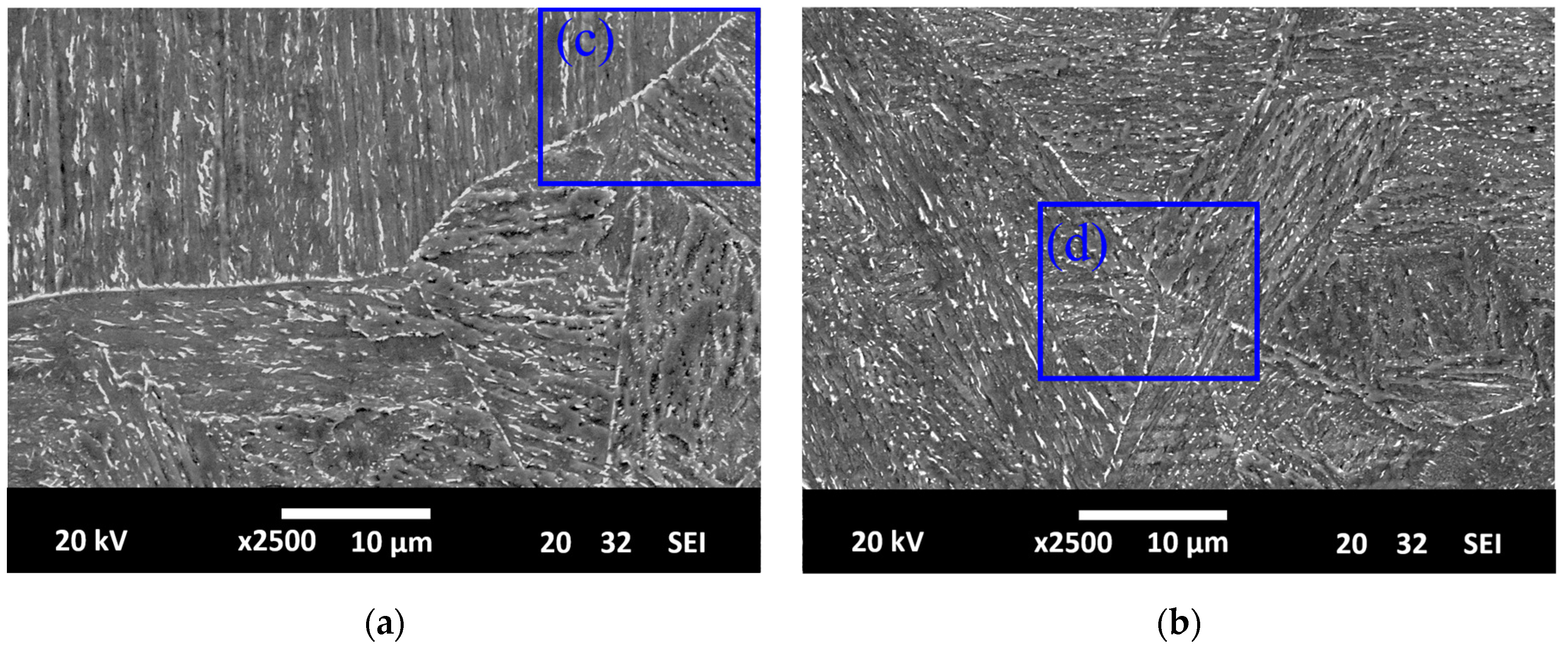
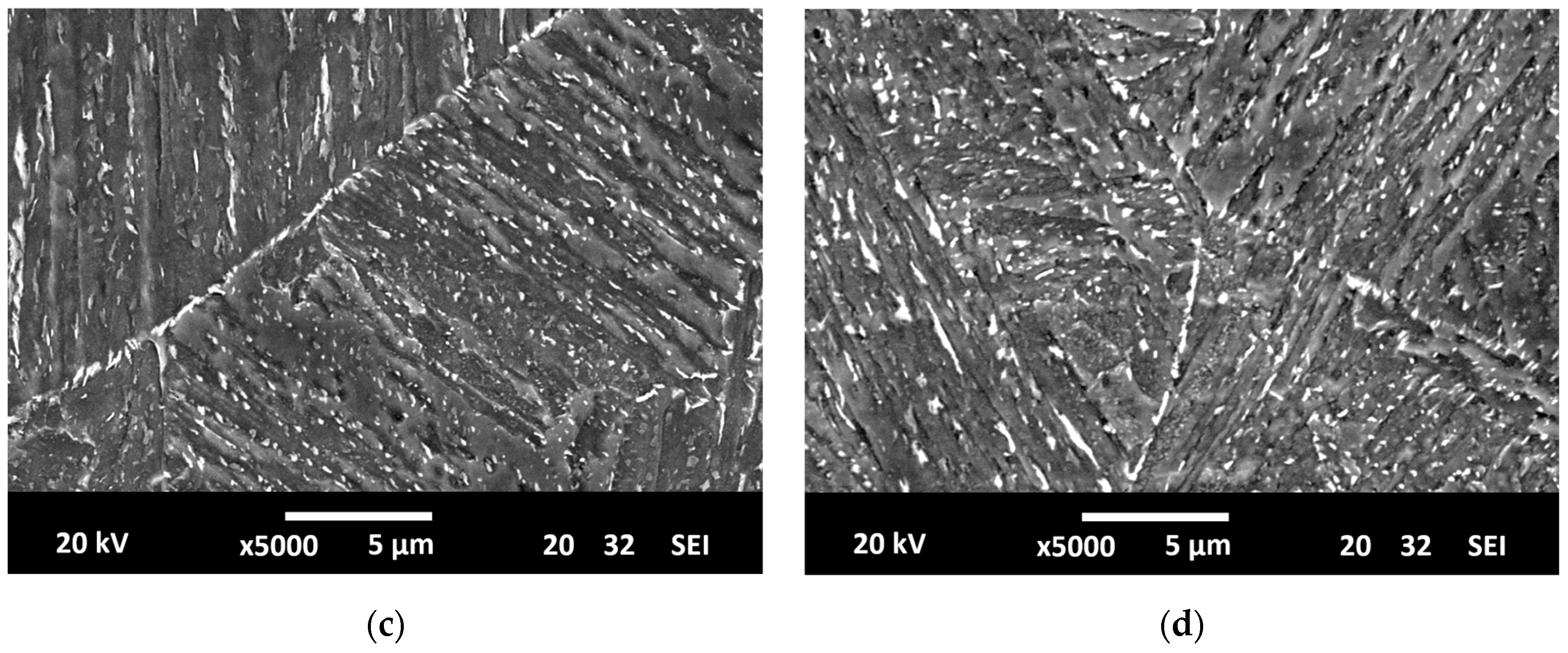
A welded joint was performed on this steel using an automatic submerged arc welding (SAW) process. A preheat temperature of 150 °C was applied, and the following welding parameters were selected: 25 V, 400 A, and a welding speed of 300 mm/min (heat input, H = 2 kJ/mm). A post-welding heat treatment (2 h at 600 °C) similar to the tempering treatment of the base metal was finally applied. Figure 1a,c show the microstructure of the coarse-grain heat-affected zone of the real weld (CGHAZ-real). Bainite laths are clearly observed with iron-chromium carbides with small amounts of molybdenum precipitated along prior austenite grain boundaries and also on bainite lath interfaces [28]. A prior austenitic grain size of 117 ± 30 μm and a Vickers hardness of 348 HV30 were measured.
The small size of the coarse-grain heat-affected zone of the real weld does not allow for machining the homogeneous specimens needed to perform the mechanical characterization of this microstructure. Therefore, a simulated coarse-grain heat-affected zone (CGHAZ-simulated) was produced by means of an appropriate heat treatment. The detailed description of how this heat treatment was defined can be found in A. Zafra et al. [29]. According to this reference, the selected heat treatment consisted of an austenitization at 1200 °C for 20 min followed by oil quenching and tempering at 600 °C for 2 h. Figure 1b shows a general image of the CGHAZ-simulated microstructure. A prior austenite grain size of 242 ± 101 μm was measured, which corresponds to welds performed under high heat inputs. Figure 1b,d show the corresponding microstructure. The similarity of this microstructure with the corresponding region of the real weld is remarkable. Again, a large number of small carbides precipitated in the course of the post-weld heat treatment (600 °C, 2 h) along prior austenite grain boundaries an on bainite lath interfaces, as can be seen in the images presented in Figure 1.
2.2. Hydrogen Diffusion and Hydrogen Charging
Hydrogen diffusion coefficients, Deff (m2/s), were calculated using a double electrolytic cell based on the one developed by Devanathan and Stachursky [30]. The time lag method was used in accordance with the ASTM G148 standard [31] to calculate Deff. Electrochemical permeation tests were carried out using an equipment similar to that described in previous works [32]. In this case, a single transient was considered for the calculation of Deff. The permeation samples had a thickness of 0.7 mm, an exposed surface of 1 cm2, and a current density of 0.50 mA/cm2 was applied on the entry side of the permeation experiment (cathodic cell) using an electrolyte composed of 1 M H2SO4 with 0.25 g/As2O3.
Hydrogen was pre-charged into the different specimens in a hydrogen reactor under a pressure of 19.5 MPa at 450 °C for 21 h [5]. The specimens were extracted from the reactor after pre-charging and introduced into liquid nitrogen (−196 °C) to avoid hydrogen egress before the mechanical tests. Samples with a length of 30 mm and a diameter of 10 mm were hydrogen pre-charged under the aforementioned conditions and thermal desorption analysis on a Leco DH603 was employed to discern the amount of hydrogen introduced into the pre-charged samples, C0. The amount of residual hydrogen, Cr, in the samples after a maintenance of 15 days in the laboratory environment was also determined. The difference between C0 and Cr represents the diffusible hydrogen, Cdiff, the values of which are shown in Table 2.
2.3. Fatigue Crack Growth Tests
The fatigue crack growth rate was determined using compact tensile CT specimens with a width W = 48 mm and thickness B = 10 mm (the other dimensions were calculated according to the ASTM E647 standard [33]). These tests were performed in a servo-hydraulic MTS 810 machine equipped with a 250 kN load cell. Crack growth was measured by means of the compliance method using a COD extensometer. Before hydrogen pre-charging, all the specimens were pre-cracked using a load ratio, R = 0.1 and a frequency of f = 10 Hz until obtaining an initial crack length versus width ratio, a/W = 0.2, following the ASTM E647 standard [33].
In order to determine the fatigue crack growth rate of the studied microstructures without hydrogen, uncharged specimens subjected to R = 0.1 and f = 10 Hz were tested in air at RT. It is well known that fatigue crack growth rates in air at room temperature is not affected by frequency [34]. In the case of the hydrogen pre-charged CGHAZ-simulated specimens, knowing that the effect of hydrogen is only noticeable at low frequencies [5,11], tests were performed using frequencies of f = 0.10 Hz and f = 0.05 Hz. Two values of load ratio, R = 0.1 and R = 0.5, were also employed in order to analyze the effect of this ratio in the hydrogen embrittlement (HE) phenomenon. It may be mentioned that we were not able to determine the threshold fatigue stress intensity range, ΔKth, of these microstructures (with relatively large hydrogen diffusion coefficients) using hydrogen pre-charged specimens because these tests require long times and most internal hydrogen would be lost.
After the completion of the fatigue tests, the fracture surfaces of the broken specimens were observed under a scanning electron microscope (SEM, JEOL-JSM5600) using an acceleration voltage of 20 kV.
3. Results
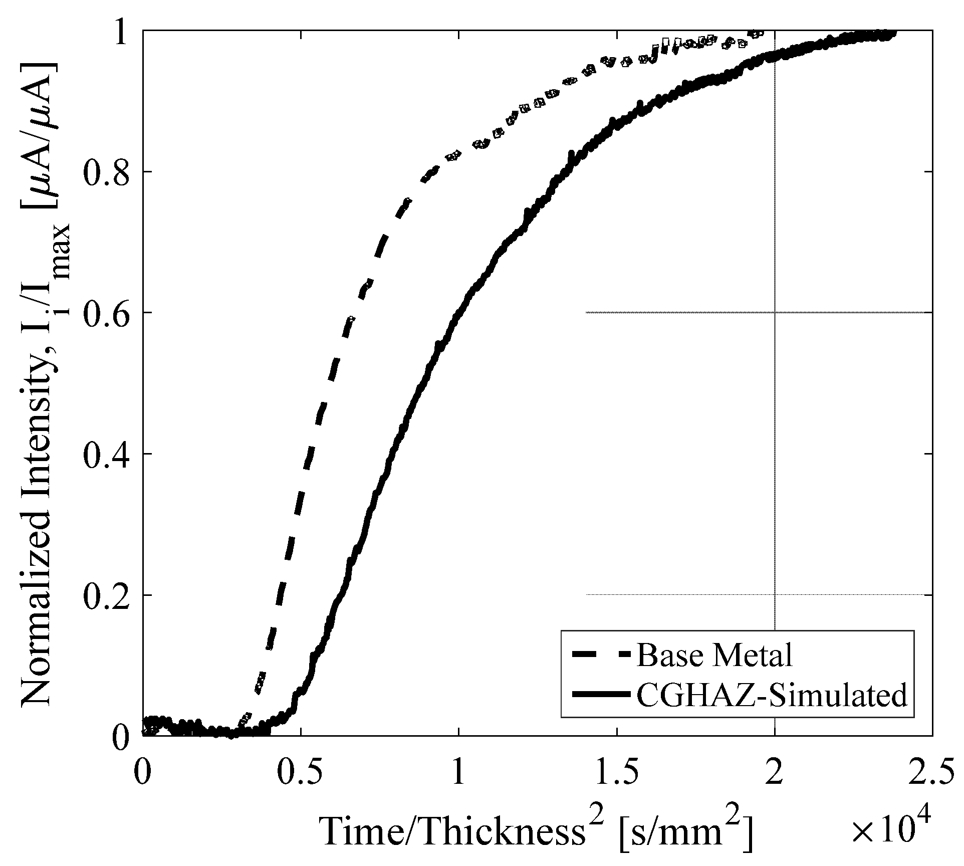
Figure 2 shows the obtained permeation curves (current detected in the anodic cell of the experimental setup) for both the BM and the CGHAZ-simulated microstructures represented in a normalized intensity (intensity divided by maximum intensity value) versus the normalized time (time divided by square of sample thickness) plot. Applying the time lag method to these curves [31], Deff was determined and the obtained results are presented in Table 2. It is noted that BM has a hydrogen diffusion coefficient slightly higher than the CGHAZ-simulated microstructure.
The amount of hydrogen introduced into the pre-charged samples (BM and CGHAZ-simulated), C0, is also reported in Table 2. As it was already mentioned, measuring the amount of residual hydrogen in the samples after a maintenance of 15 days in the laboratory environment (0.60 ppm for BM and 0.97 ppm for GCHAZ-simulated), the difference between the initial and the residual hydrogen is the diffusible hydrogen, Cdiff. As can be seen in Table 2, the initial hydrogen content in both microstructures was quite similar, 1.27 ppm and 1.42 ppm for BM and CGHAZ-simulated respectively, and the diffusible hydrogen was slightly higher in the BM (0.67 ppm) than in the CGHAZ-simulated (0.45 ppm).
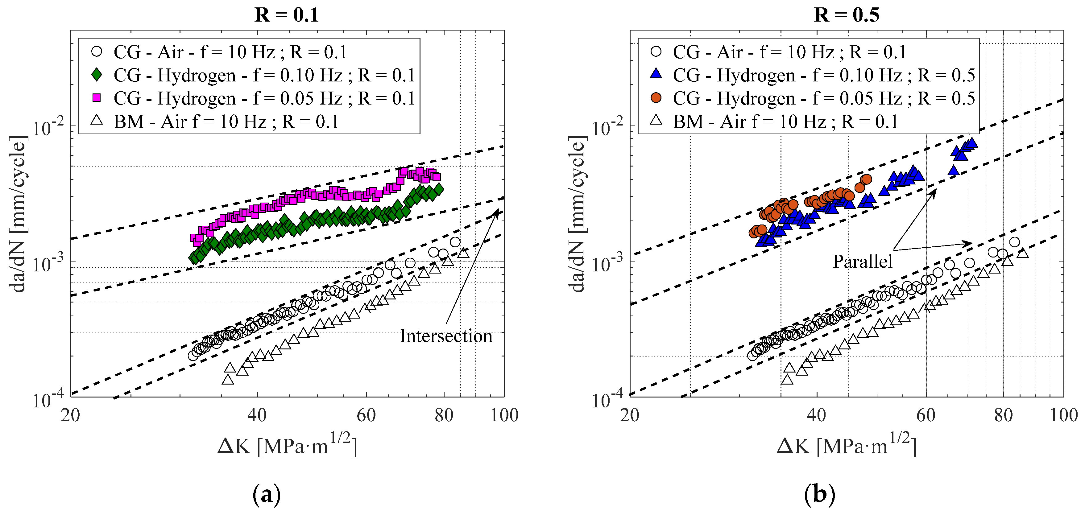
Figure 3 shows the fatigue crack growth rate (da/dN) versus the stress intensity factor range (ΔK) obtained with the pre-charged CGHAZ-simulated specimens at different load ratios R = 0.1 (Figure 3a) and R = 0.5 (Figure 3b) using different frequencies (f = 0.10 and 0.05 Hz). The da/dN vs. ΔK curves obtained with the uncharged specimens of the base metal (BM) and CGHAZ-simulated microstructures (empty symbols) were also included in these two plots. We only performed tests under R = 0.1 in absence of hydrogen.
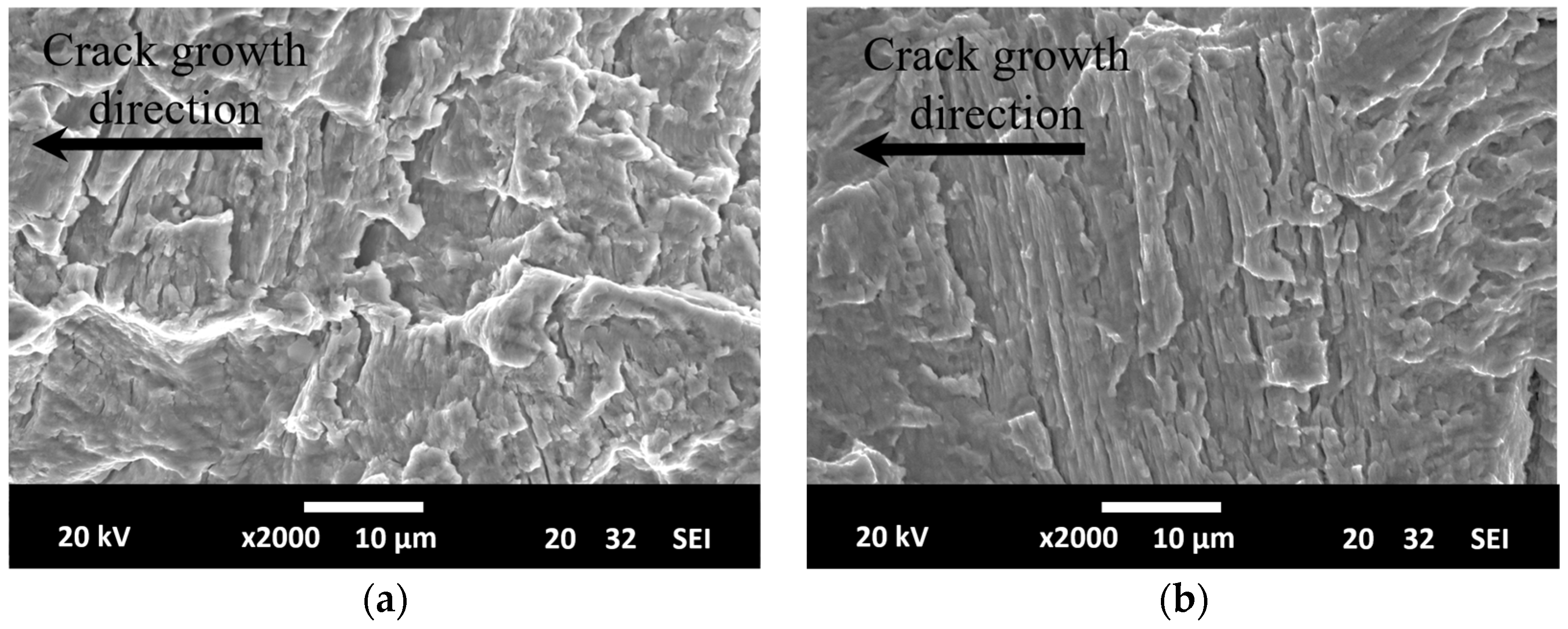
First at all, the fatigue crack growth rate measured in absence of internal hydrogen (empty symbols) on CGHAZ-simulated was significantly higher (1.5–2.0 times greater at all ΔK) than on BM. The coarser microstructure and higher hardness (and strength) of the CGHAZ-simulated microstructure explains this behavior. Nevertheless, this difference was not observed on their fracture surfaces. As shown in Figure 4, the fracture micromechanisms operative in both steel microstructures, characterized by the presence of striation marks, were identical, evidencing considerable plasticity during crack growth due to blunting phenomena. Furthermore, this ductile appearance is in agreement with the microvoids coalescence (MVC) micromechanism observed on the failure surfaces in the fracture toughness tests performed in air on the same microstructures (without hydrogen and hydrogen pre-charged) [29].
On the other hand, the influence of hydrogen in the fatigue crack growth rate of the CGHAZ-simulated microstructure was evident. For the R = 0.1 load ratio (Figure 3a) and a frequency f = 0.10 Hz, the fatigue crack growth rate of the steel with internal hydrogen increased in almost one order of magnitude at the beginning of the test (ΔK = 32 MPa). It is also worth noting the decrease on the fatigue crack growth rate difference between the hydrogen pre-charged and the uncharged samples as test progressed, although the fatigue crack growth rate of the hydrogen pre-charged microstructure remained appreciably higher even at ΔK = 80 MPa√m. Furthermore, for the same load ratio (R = 0.1), the fatigue crack growth rate increase was even higher when a smaller frequency was applied (f = 0.05 Hz).
Under a load ratio R = 0.5 (Figure 3b), the increment on the fatigue crack growth rate in presence of internal hydrogen at f = 0.1 Hz was even more marked than for R = 0.1 and, in this case, such increment remains approximately constant for the whole applied stress intensity factor range, since the slopes of the da/dN versus ΔK curves of the hydrogen pre-charged and uncharged steels were practically identical. In this case, the use of a lower frequency (f = 0.05 Hz) also produced a small increment in the fatigue crack growth rate at the beginning of the test. However, as the test progressed, both curves (f = 0.05 and f = 0.10) tended to converge.
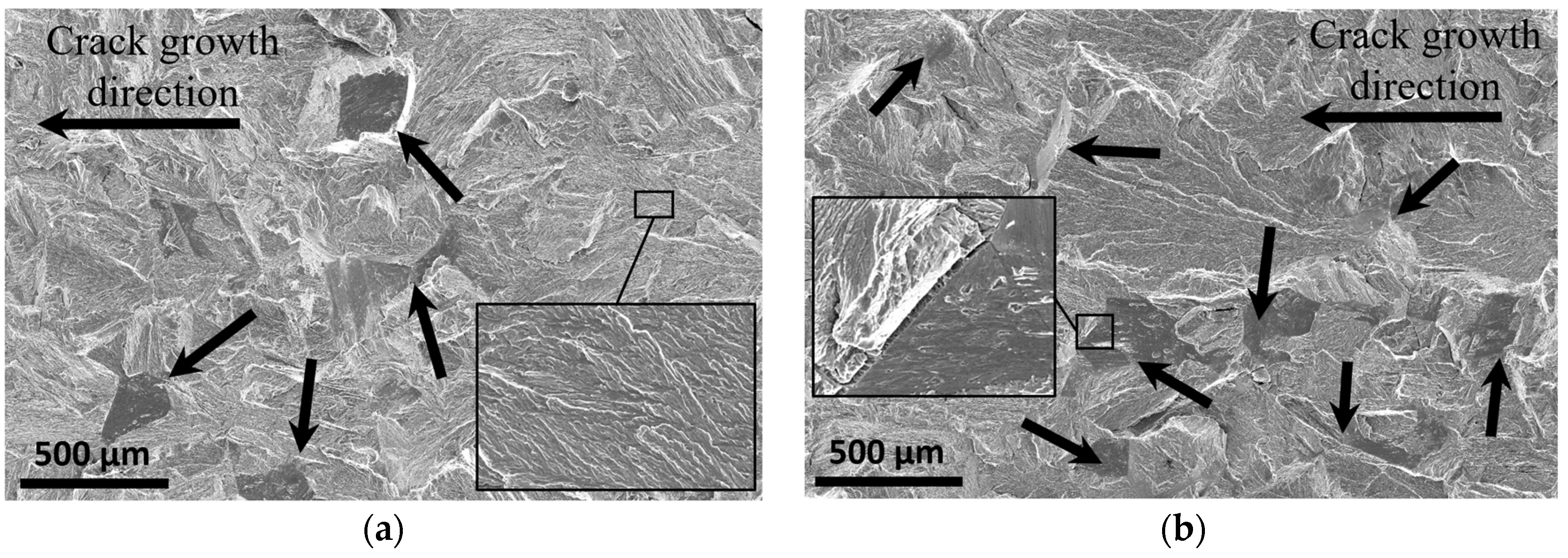
The fatigued surfaces of all these specimens were analyzed under the scanning electron microscope. Figure 5 shows some fracture surfaces of hydrogen pre-charged CGHAZ-simulated specimens with R = 0.1, at the beginning of the test (ΔK = 35 MPa) for the two applied fatigue frequencies. It was noticed that, even under the highest frequency (Figure 5a), the fracture surface of these specimens differed from the uncharged ones. In agreement with the observations of Murakami et al. [35] on a similar steel, when these quenched and tempered steels were fatigue tested with internal hydrogen, the crack tip plasticity responsible of fatigue striations was not observed, but the main operative failure micromechanism was in this case bainite lath descohesion (BLD, see insert of Figure 5a), decohesion along the bainite interfaces (microstructural units observed in the insert of Figure 5a have similar size and morphology than bainite laths, Figure 1b,d), which is the same as that which also appears under static loads in fracture tests characterization with internal hydrogen [29]. Moreover, some areas with intergranular fracture (IG) are also appreciated in the images of Figure 5 (marked with black arrows) with dimensions comparable to the prior austenite grain size present in this microstructure (see Table 2). The presence of these failure micromechanisms supports the strong embrittlement of this microstructure tested under internal hydrogen. When a lower frequency was applied (Figure 5b), a greater fraction of the intergranular fracture micromechanism was observed, in agreement with the larger hydrogen effect shown in the specimens tested at this frequency.
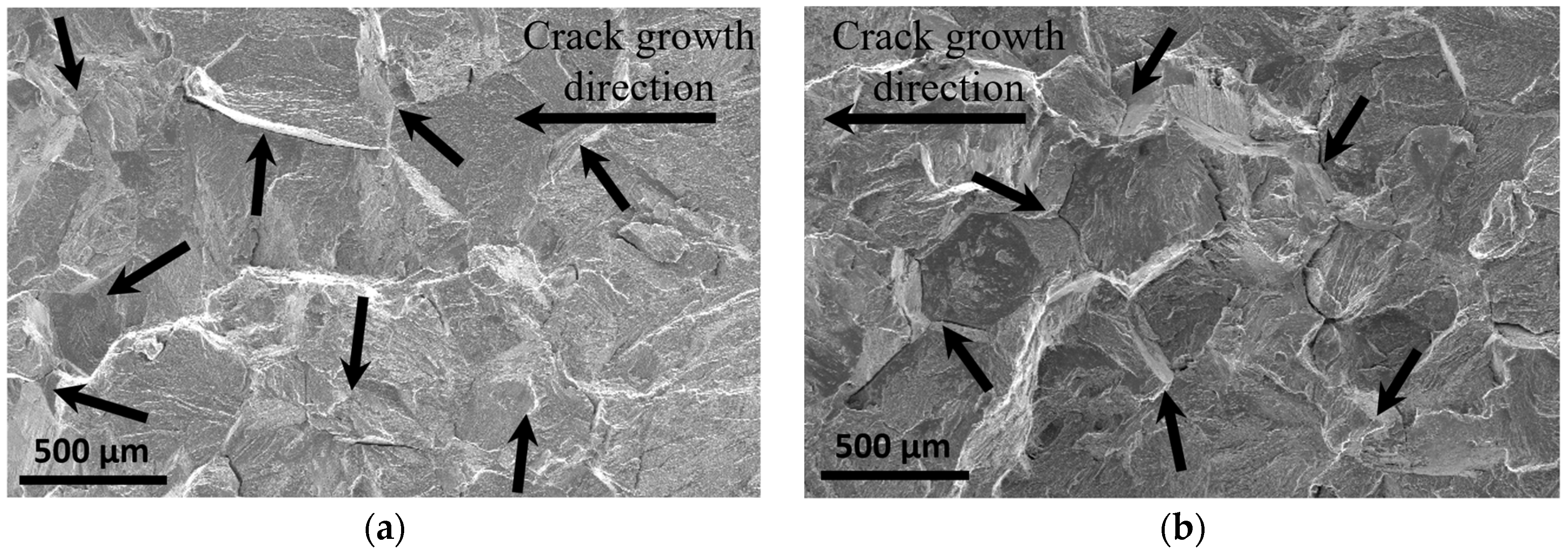
Figure 6 shows images at the beginning of the test (ΔK = 35 MPa) corresponding to fracture surfaces of H-precharged CGHAZ-simulated specimens tested with a load ratio R = 0.5 and frequencies of 0.10 Hz (Figure 6a) and 0.05 Hz (Figure 6b). The observed fracture micromechanisms are the same as those previously noticed for R = 0.1 (BLD and IG), but now, from the beginning to the end of the fatigue test, the main micromechanism was intergranular fracture (IG), bainite lath decohesion (BLD) being secondary. This explains the higher hydrogen embrittlement measured under these test conditions.
As it was stated in previous works [29], this steel is somewhat susceptible to tempering brittleness, which consists of the precipitation of impurities in the prior austenitic grain boundaries, this fact being especially important in coarse-grained microstructures, promoting intergranular fracture.
Table 3 summarizes the fracture micromechanisms observed in the CGHAZ-simulated specimens under the different testing conditions.
4. Discussion
The fatigue crack growth rate results obtained in the aforementioned experiments show the embrittlement phenomenon induced by the presence of internal hydrogen in the CGHAZ microstructure of a CrMo steel, and how this hydrogen effect increases when lower test frequencies and higher fatigue load ratios are applied.
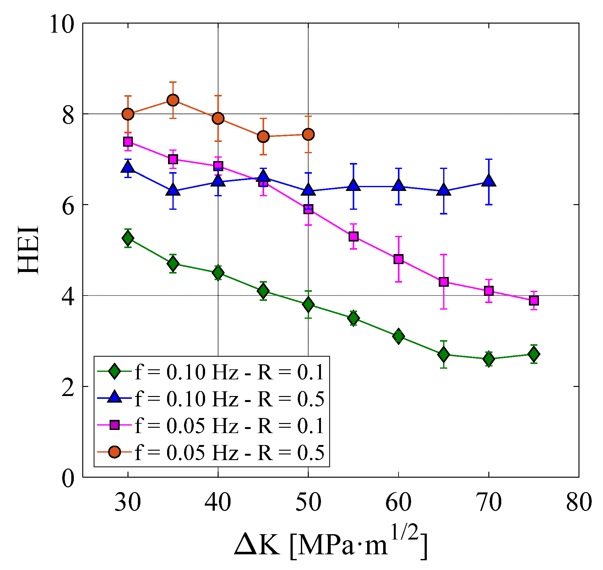
In order to have a quantitative comparison of the effect of the different test variables on the fatigue crack growth behavior, the hydrogen embrittlement index defined in expression (1), which compares the fatigue crack growth rate of uncharged and hydrogen pre-charged specimens, was used throughout the tests carried out under the different conditions. The obtained results are presented in Figure 7. Under a load ratio R = 0.1, embrittlement indices of 5 and 7 were respectively measured at the beginning of the test under 0.1 Hz and 0.05 Hz frequencies. However, in this case, both embrittlement indexes, and therefore the effect of hydrogen on the crack growth rate, decreased as the crack grew (ΔK increased), this decrease being slightly greater under the lowest frequency. On the other hand, when the applied load ratio was higher (R = 0.5), the embrittlement index measured at the beginning of the test was approximately 7 for the highest frequency (f = 0.1 Hz) and around 8 for the lowest one (f = 0.05 Hz) and, in both cases, these embrittlement indices remained approximately constant throughout the entire test.
When pre-cracked hydrogen pre-charged specimens were mechanically tested in air at RT (ex-situ tests), two opposite diffusion phenomena, which dispute internal hydrogen, took place. The first one is due to the stress triaxiality generated just ahead of the crack front. Hydrogen atoms are attracted to this region submitted to high local stress triaxiality, promoting high local hydrogen concentration in the so-called process zone. According to the Oriani theory [36], an equilibrium expressed by Equation (2) is attained between the local hydrogen concentration in this process zone, CHloc, and hydrogen concentration in the surrounding non-stressed region, CH0 (CH0 may in this case correspond to the diffusible hydrogen, Cdiff, 0.45 ppm, Table 2):
where σH is the hydrostatic stress and VH the partial molar volume of hydrogen, which is approximately 2 × 10⁻⁶ m3/mol in ferritic microstructures. The maximum hydrostatic stress in the front of the crack in an elasto-plastic material can be approximated to 2.5 times the steel yield strength, σYS, and it is located at a distance from the crack tip, x0, that increases as the applied load does [37,38]:
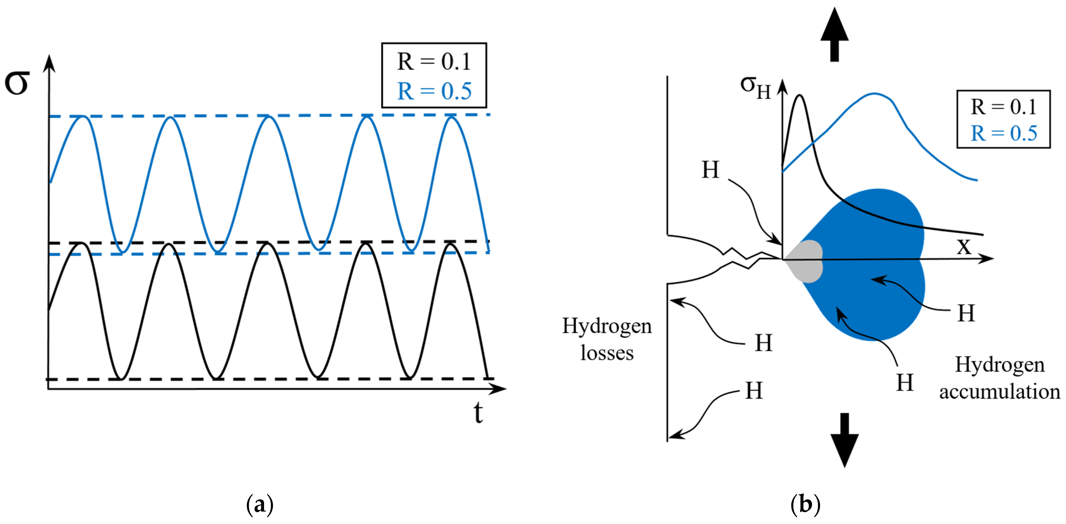
where, E is the elastic modulus, ν the Poisson ratio, J the applied J-integral, and Kmax the maximum value of the stress intensity factor. Taking Kmax values of 33 and 82 MPa for R = 0.1 at the beginning and at the end of the fatigue test, x0 values of 5.3 and 33 μm were respectively obtained (an elastic modulus of 200 GPa was considered along with the yield strength reported in Table 2). Repeating now the same calculations with R = 0.5, x0 varied between 21 and 131 µm: the distance from the crack tip where maximum hydrogen accumulation takes places (location of the maximum hydrostatic stress) increased four times when the stress ratio R changed from 0.1 to 0.5.
The second diffusion phenomenon taking place in a hydrogen pre-charged specimen is based on the hydrogen concentration gradient due to the difference between the high hydrogen concentration inside the sample and the non-hydrogenated exterior environment (air). This gradient causes the continuous egress of hydrogen from the sample.
In this context, when a low fatigue load ratio (R = 0.1) was applied, although the hydrostatic stress at the crack front was able to concentrate a large amount of hydrogen in the process zone at the beginning of the test, and with the increase of testing time significant hydrogen losses took place, as hydrogen accumulated at a short distance to the crack tip (see Figure 8) and the embrittlement process was gradually reduced, a fact which was reflected in a decreasing HEI.
On the other hand, when a higher load ratio was used (R = 0.5), for the same value of ΔK, Kmin and Kmax were higher and the corresponding maximum of the hydrostatic stress, where hydrogen accumulation takes place, moved to higher distances from the crack tip (see Figure 8). In this case, the local hydrogen concentration in the process zone derived from Equation (2) was enough to compensate hydrogen losses through sample surfaces, maintaining high local hydrogen concentrations and a nearly constant embrittlement effect during the whole fatigue test. This behavior had already been reported by other researchers in other steel grades [39]. They agree in the existence of certain conditions that facilitate that a critical hydrogen concentration is reached in the process zone, causing maximum embrittlement.
On the other hand, the intergranular failure mechanism is only triggered when a large enough material volume (in relation to the steel prior austenitic grain size) is submitted to high hydrostatic stresses and hydrogen accumulation on such interfaces attain a critical value, explaining the greater fraction of IG observed under higher stress ratios and lower frequencies (Figure 5 and Figure 6). According to the physical-based micromechanical model developed by Novak et al. [40], dislocations pile-ups impinging in grain boundary carbides into the process region lead to grain boundary decohesion and in turn to intergranular fracture. However, the maintenance of this critical concentration will depend on the testing variables (frequency and stress ratio), as there is a constant struggle between hydrogen egress from the sample to the surrounding environment and hydrogen accumulation provided by the hydrostatic stress produced in the process zone ahead of the crack.
5. Conclusions
The fatigue crack growth study performed to analyze the embrittlement effect of internal hydrogen in a coarse-grained CrMo steel can be finally summarized in the following conclusions:
Using a gaseous pressure pre-charging method, a hydrogen concentration of 1.4 ppm was introduced into the CGHAZ-simulated steel microstructure.
Under a fatigue stress ratio R = 0.1, fatigue crack growth rates 5 and 7 times higher than that obtained in air were respectively measured at the beginning of the fatigue test under frequencies of 0.1 and 0.05, but this difference progressively decreased as the test progressed.
When a higher load ratio was applied (R = 0.5), the hydrogen embrittlement index attained a value around 7–8, for both frequencies, remaining approximately constant throughout the test. Under such testing conditions, the stress triaxiality developed in the process zone was high enough to guarantee a sufficient hydrogen concentration throughout the test, compensating for the egress of hydrogen from the test specimen to the surrounding air.
The embrittlement phenomena produced by the presence of internal hydrogen also manifested in a clear modification of the failure mechanism, which changed from ductile in the absence of hydrogen to brittle in the hydrogen pre-charged samples. Under the lower load ratio (R = 0.1), the predominant micromechanism was bainitic lath decohesion (BLD) with traces of intergranular fracture (IG), but when a higher load ratio was applied (R = 0.5), intergranular fracture (IG) became the predominant failure micromechanism.
Author Contributions
Conceptualization, G.Á., A.Z., F.J.B. and C.R.; methodology, G.Á., A.Z., F.J.B. and C.R.; software, G.Á., A.Z. and C.R.; validation, G.Á., A.Z., F.J.B. and C.R.; formal analysis, G.Á. and A.Z.; investigation, G.Á., A.Z., F.J.B. and C.R.; resources, F.J.B. and C.R.; data curation, G.Á., A.Z., F.J.B., and C.R.; writing—original draft preparation, G.Á. and C.R.; writing—review and editing, G.Á., A.Z., F.J.B. and C.R.; visualization, G.Á., A.Z., F.J.B. and C.R.; supervision, F.J.B. and C.R.; project administration, F.J.B. and C.R.; funding acquisition, F.J.B. and C.R. All authors have read and agreed to the published version of the manuscript.
Funding
This work was supported by the Spanish Ministry of Science, Innovation and Universities RTI2018-096070-B-C31 and the Principality of Asturias AYUD-2021-50985.
Institutional Review Board Statement
Not applicable.
Informed Consent Statement
Not applicable.
Data Availability Statement
Data of the main values of results are included in the manuscript. At this time, the data also forms part of an ongoing study.
Acknowledgments
To the Spanish Ministry of Science, Innovation and Universities (RTI2018-096070-B-C31). To the Principality of Asturias (AYUD-2021-50985) and the G. Álvarez and A. Zafra Severo Ochoa grants, PA-20-PF-BP19-087 and PA-18-PF-BP17-038 respectively. To the Scientific-Technical Services of the University of Oviedo for the use of the SEM JEOL-JSM5600 scanning electron microscope.
Conflicts of Interest
The authors declare no conflict of interest.
References
- AbouSeada, N.; Hatem, T.M. Climate action: Prospects of green hydrogen in Africa. Energy Rep. 2022, 8, 3873–3890. [Google Scholar] [CrossRef]
- Laureys, A.; Depraetere, R.; Cauwels, M.; Depover, T.; Hertelé, S.; Verbeken, K. Use of existing steel pipeline infrastructure for gaseous hydrogen storage and transport: A review of factors affecting hydrogen induced degradation. J. Nat. Gas Sci. Eng. 2022, 101, 104534. [Google Scholar] [CrossRef]
- Chapman, A.; Itaoka, K.; Farabi-Asl, H.; Fujii, Y. Nakahara, Societal penetration of hydrogen into the future energy system: Impacts of policy, technology and carbon targets. Int. J. Hydrogen Energy 2020, 45, 3883–3898. [Google Scholar] [CrossRef]
- Nykyforchyn, H.; Zvirko, O.; Hredil, M.; Krechkovska, H.; Tsyrulnyk, O.; Student, O.; Unigovskyi, L. Methodology of hydrogen embrittlement study of long-term operated natural gas distribution pipeline steels caused by hydrogen transport. Frat. Ed Integrita Strutt. 2022, 16, 396–404. [Google Scholar] [CrossRef]
- Peral, L.B.; Zafra, A.; Blasón, S.; Rodríguez, C.; Belzunce, J. Effect of hydrogen on the fatigue crack growth rate of quenched and tempered CrMo and CrMoV steels. Int. J. Fatigue 2019, 120, 201–214. [Google Scholar] [CrossRef]
- Alvaro, A.; Wan, D.; Olden, V.; Barnoush, A. Hydrogen enhanced fatigue crack growth rates in a ferritic Fe-3 wt%Si alloy and a X70 pipeline steel. Eng. Fract. Mech. 2019, 219, 106641. [Google Scholar] [CrossRef]
- Pallaspuro, S.; Yu, H.; Kisko, A.; Porter, D.; Zhang, Z. Fracture toughness of hydrogen charged as-quenched ultra-high-strength steels at low temperatures. Mater. Sci. Eng. A 2017, 688, 190–201. [Google Scholar] [CrossRef] [Green Version]
- Martínez-Pañeda, E.; Harris, Z.D.; Fuentes-Alonso, S.; Scully, J.R.; Burns, J.T. On the suitability of slow strain rate tensile testing for assessing hydrogen embrittlement susceptibility. Corros. Sci. 2019, 163, 108291. [Google Scholar] [CrossRef] [Green Version]
- Álvarez, G.; Peral, L.B.; Rodríguez, C.; García, T.E.; Belzunce, F.J. Hydrogen embrittlement of structural steels: Effect of the displacement rate on the fracture toughness of high-pressure hydrogen pre-charged samples. Int. J. Hydrogen Energy 2019, 44, 15634–15643. [Google Scholar] [CrossRef]
- Zafra, A.; Álvarez, G.; Belzunce, J.; Rodríguez, C. Influence of tempering time on the fracture toughness of hydrogen pre-charged 42CrMo4 steel. Theor. Appl. Fract. Mech. 2022, 117, 103197. [Google Scholar] [CrossRef]
- Shinko, T.; Hénaff, G.; Halm, D.; Benoit, G.; Bilotta, G.; Arzaghi, M. Hydrogen-affected fatigue crack propagation at various loading frequencies and gaseous hydrogen pressures in commercially pure iron. Int. J. Fatigue 2019, 121, 197–207. [Google Scholar] [CrossRef]
- Álvarez, G.; Zafra, A.; Belzunce, F.J.; Rodríguez, C. Hydrogen embrittlement analysis in a CrMoV steel by means of sent specimens, Theor. Appl. Fract. Mech. 2020, 106, 102450. [Google Scholar] [CrossRef]
- Álvarez, G.; Zafra, A.; Belzunce, F.J.; Rodríguez, C. Hydrogen embrittlement testing procedure for the analysis of structural steels with Small Punch Tests using notched specimens. Eng. Fract. Mech. 2021, 253, 107906. [Google Scholar] [CrossRef]
- Zafra, A.; Peral, L.B.; Belzunce, J.; Rodríguez, C. Effect of hydrogen on the tensile properties of 42CrMo4 steel quenched and tempered at different temperatures. Int. J. Hydrogen Energy 2018, 43, 9068–9082. [Google Scholar] [CrossRef]
- Colombo, C.; Fumagalli, G.; Bolzoni, F.; Gobbi, G. Fatigue behavior of hydrogen pre-charged low alloy Cr–Mo steel. Int. J. Fatigue 2016, 83, 2–9. [Google Scholar] [CrossRef]
- Lee, S.G.; Kim, I.S. Effect of pre-charged hydrogen on fatigue crack growth of low alloy steel at 288 °C. Mater. Sci. Eng. A 2006, 420, 279–285. [Google Scholar] [CrossRef]
- Sun, Z.; Benoit, G.; Moriconi, C.; Hamon, F.; Halm, D.; Hamon, G.F. Hénaff, Fatigue crack propagation under gaseous hydrogen in a precipitation-hardened martensitic stainless steel. Int. J. Hydrogen Energy 2011, 36, 8641–8644. [Google Scholar] [CrossRef]
- Meng, B.; Gu, C.; Zhang, L.; Zhou, C.; Li, X.; Zhao, Y.; Zheng, J.; Chen, X.; Han, Y. Hydrogen effects on X80 pipeline steel in high-pressure natural gas/hydrogen mixtures. Int. J. Hydrogen Energy 2017, 42, 7404–7412. [Google Scholar] [CrossRef]
- Macadre, A.; Artamonov, M.; Matsuoka, S.; Furtado, J. Effects of hydrogen pressure and test frequency on fatigue crack growth properties of Ni–Cr–Mo steel candidate for a storage cylinder of a 70 MPa hydrogen filling station. Eng. Fract. Mech. 2011, 78, 3196–3211. [Google Scholar] [CrossRef]
- Slifka, A.J.; Drexler, E.S.; Nanninga, N.E.; Levy, Y.S.; McColskey, J.D.; Amaro, R.L.; Stevenson, A.E. Fatigue crack growth of two pipeline steels in a pressurized hydrogen environment. Corros. Sci. 2014, 78, 313–321. [Google Scholar] [CrossRef]
- Yamabe, J.; Matsunaga, H.; Furuya, Y.; Hamada, S.; Itoga, H.; Yoshikawa, M.; Takeuchi, E.; Matsuoka, S. Qualification of chromium–molybdenum steel based on the safety factor multiplier method in CHMC1-2014. Int. J. Hydrogen Energy 2015, 40, 719–728. [Google Scholar] [CrossRef]
- Briottet, L.; Moro, I.; Escot, M.; Furtado, J.; Bortot, P.; Tamponi, G.M.; Solin, J.; Odemer, G.; Blanc, C.; Andrieu, E. Fatigue crack initiation and growth in a CrMo steel under hydrogen pressure. Int. J. Hydrogen Energy 2015, 40, 17021–17030. [Google Scholar] [CrossRef] [Green Version]
- Saxena, A.; Nibur, K.; Prakash, A. Applications of fracture mechanics in assessing integrity of hydrogen storage systems. Eng. Fract. Mech. 2018, 187, 368–380. [Google Scholar] [CrossRef]
- Zhao, W.; Yang, M.; Zhang, T.; Deng, Q.; Jiang, W.; Jiang, W. Study on hydrogen enrichment in X80 steel spiral welded pipe. Corros. Sci. 2018, 133, 251–260. [Google Scholar] [CrossRef]
- Cheng, X.; Cheng, X.; Jiang, C.; Zhang, X.; Wen, Q. Hydrogen diffusion and trapping in V-microalloyed mooring chain steels. Mater. Lett. 2018, 213, 118–121. [Google Scholar] [CrossRef]
- Guedes, D.; Malheiros, L.C.; Oudriss, A.; Cohendoz, S.; Bouhattate, J.; Creus, J.; Thébault, F.; Piette, M.; Feaugas, X. The role of plasticity and hydrogen flux in the fracture of a tempered martensitic steel: A new design of mechanical test until fracture to separate the influence of mobile from deeply trapped hydrogen. Acta Mater. 2020, 186, 133–148. [Google Scholar] [CrossRef]
- Álvarez, G.; Zafra, A.; Rodríguez, C.; Belzunce, F.J.; Cuesta, I.I. SPT analysis of hydrogen embrittlement in CrMoV welds. Theor. Appl. Fract. Mech. 2020, 110, 102813. [Google Scholar] [CrossRef]
- Parvathavarthini, N.; Saroja, S.; Dayal, R.K.; Khatak, H.S. Studies on hydrogen permeability of 2.25% Cr–1% Mo ferritic steel: Correlation with microstructure. J. Nucl. Mater. 2001, 288, 187–196. [Google Scholar] [CrossRef]
- Zafra, A.; Álvarez, G.; Belzunce, J.; Alegre, J.M.; Rodríguez, C. Fracture toughness of coarse-grain heat affected zone of quenched and tempered CrMo steels with internal hydrogen: Fracture micromechanisms. Eng. Fract. Mech. 2021, 241, 107433. [Google Scholar] [CrossRef]
- Devanathan, M.A.V.; Stachurski, Z. The Adsorption and Diffusion of Electrolytic Hydrogen in Palladium. Available online: https://royalsocietypublishing.org/ (accessed on 26 March 2022).
- ASTM G148; Standard Practice for Evaluation of Hydrogen Uptake, Permeation, and Transport in Metals by an Electrochemical Technique. ASTM: West Conshohocken, PA, USA, 2011. [CrossRef]
- Zafra, A.; Peral, L.B.; Belzunce, J. Hydrogen diffusion and trapping in A 42CrMo4 quenched and tempered steel: Influence of tempering temperature. Int. J. Hydrogen Energy. 2020, 45, 31225–31242. [Google Scholar] [CrossRef]
- ASTM E647; Standard Test Method for Measurement of Fatigue Crack Growth Rates. ASTM: West Conshohocken, PA, USA, 2016.
- Barsom, J.M.; Rolfe, S.T. Fracture and Fatigue Control in Structures: Applications of Fracture Mechanics; ASTM: West Conshohocken, PA, USA, 1999. [Google Scholar]
- Murakami, Y.; Matsuoka, S. Effect of hydrogen on fatigue crack growth of metals. Eng. Fract. Mech. 2010, 77, 1926–1940. [Google Scholar] [CrossRef] [Green Version]
- Oriani, R. The diffusion and trapping of hydrogen in steel. Acta Metall. 1970, 18, 147–157. [Google Scholar] [CrossRef]
- Sofronis, P.; McMeeking, R.M. Numerical analysis of hydrogen transport near a blunting crack tip. J. Mech. Phys. Solids 1989, 37, 317–350. [Google Scholar] [CrossRef]
- Anderson, T.L. Fracture mechanics Fundamentals and Applications, Angew. Chemie Int. Ed. 2001. [Google Scholar] [CrossRef]
- Djukic, M.B.; Bakic, G.M.; Zeravcic, V.S.; Sedmak, A.; Rajicic, B. The synergistic action and interplay of hydrogen embrittlement mechanisms in steels and iron: Localized plasticity and decohesion. Eng. Fract. Mech. 2019, 216, 106528. [Google Scholar] [CrossRef]
- Novak, P.; Yuan, R.; Somerday, B.P.; Sofronis, P.; Ritchie, R.O. A statistical, physical-based, micro-mechanical model of hydrogen-induced intergranular fracture in steel. J. Mech. Phys. Solids 2010, 58, 206–226. [Google Scholar] [CrossRef]
Figure 1.
CGHAZ microstructures. (a,c) Real weld: ×2500 and ×5000; (b,d) Simulated weld: ×2500 and ×5000.
Figure 1.
CGHAZ microstructures. (a,c) Real weld: ×2500 and ×5000; (b,d) Simulated weld: ×2500 and ×5000.


Figure 2.
Hydrogen permeation tests results.

Figure 3.
Fatigue crack growth test curves obtained in hydrogen pre-charged CGHAZ-simulated. (a) R = 0.1; (b) R = 0.5.
Figure 3.
Fatigue crack growth test curves obtained in hydrogen pre-charged CGHAZ-simulated. (a) R = 0.1; (b) R = 0.5.

Figure 4.
SEM fracture surfaces of uncharged specimens. (a) BS (ΔK = 35 MPa); (b) CGHAZ (ΔK = 35 MPa ).
Figure 4.
SEM fracture surfaces of uncharged specimens. (a) BS (ΔK = 35 MPa); (b) CGHAZ (ΔK = 35 MPa ).

Figure 5.
SEM fracture surfaces of hydrogen pre-charged specimens tested at R = 0.1 and ΔK = 35 MPa. (a) f = 0.1 Hz; (b) f = 0.05 Hz.
Figure 5.
SEM fracture surfaces of hydrogen pre-charged specimens tested at R = 0.1 and ΔK = 35 MPa. (a) f = 0.1 Hz; (b) f = 0.05 Hz.

Figure 6.
SEM fracture surfaces of hydrogen pre-charged specimens tested at R = 0.5 and ΔK = 35 MPa. (a) f = 0.1 Hz; (b) f = 0.05 Hz.
Figure 6.
SEM fracture surfaces of hydrogen pre-charged specimens tested at R = 0.5 and ΔK = 35 MPa. (a) f = 0.1 Hz; (b) f = 0.05 Hz.

Figure 7.
Evolution of the HEI in the fatigue crack growth rate along the different tests.

Figure 8.
(a) Stress cycles (R = 0.1 and 0.5) with the same Δσ; (b) Hydrostatic stress distribution in front of the crack for R = 0.1 and 0.5.
Figure 8.
(a) Stress cycles (R = 0.1 and 0.5) with the same Δσ; (b) Hydrostatic stress distribution in front of the crack for R = 0.1 and 0.5.


Table 1.
Chemical composition in wt. % of 2.25Cr1Mo steel.
| %C | %Mn | %Si | %P | %S | %Cr | %Mo | %Ni |
|---|---|---|---|---|---|---|---|
| 0.14 | 0.56 | 0.16 | 0.005 | 0.002 | 2.23 | 1.00 | 0.09 |
Table 2.
Tensile mechanical properties (yield strength, σYS, tensile strength, σu, elongation, E, reduction of area, Z), Vickers hardness, grain size, diffusion coefficient, and hydrogen concentrations.
Table 2.
Tensile mechanical properties (yield strength, σYS, tensile strength, σu, elongation, E, reduction of area, Z), Vickers hardness, grain size, diffusion coefficient, and hydrogen concentrations.
| Material | σYS (MPa) | σu (MPa) | E (%) | Z (%) | HV30 (-) | Grain Size (μm) | Deff (m2/s) | C0 (ppm) | Cdiff (ppm) |
|---|---|---|---|---|---|---|---|---|---|
| Base Metal | 761 | 895 | 21 | 71 | 298 | 21 | 3.4 × 10⁻¹¹ | 1.27 | 0.67 |
| CGHAZ-simulated | 931 | 1036 | 16 | 72 | 321 | 242 | 2.3 × 10⁻¹¹ | 1.42 | 0.45 |
Table 3.
Fracture micromechanisms observed on the fatigue crack growth test surfaces.
| Material | Fatigue Parameters | Fracture Micromechanisms | ||
|---|---|---|---|---|
| Condition | R | f (Hz) | ||
| BM | Air | 0.1 | 10.00 | Striations |
| CGHAZ-simulated | Air | 0.1 | 10.00 | Striations |
| Hydrogen | 0.1 | 0.10 | BLD + IG | |
| 0.1 | 0.05 | BLD + IG | ||
| 0.5 | 0.10 | IG + BLD | ||
| 0.5 | 0.05 | IG + BLD | ||
Publisher’s Note: MDPI stays neutral with regard to jurisdictional claims in published maps and institutional affiliations. |
© 2022 by the authors. Licensee MDPI, Basel, Switzerland. This article is an open access article distributed under the terms and conditions of the Creative Commons Attribution (CC BY) license (https://creativecommons.org/licenses/by/4.0/).
Share and Cite
MDPI and ACS Style
Álvarez, G.; Zafra, A.; Belzunce, F.J.; Rodríguez, C. Effect of Internal Hydrogen on the Fatigue Crack Growth Rate in the Coarse-Grain Heat-Affected Zone of a CrMo Steel. Metals 2022, 12, 673. https://doi.org/10.3390/met12040673
AMA Style
Álvarez G, Zafra A, Belzunce FJ, Rodríguez C. Effect of Internal Hydrogen on the Fatigue Crack Growth Rate in the Coarse-Grain Heat-Affected Zone of a CrMo Steel. Metals. 2022; 12(4):673. https://doi.org/10.3390/met12040673
Chicago/Turabian StyleÁlvarez, Guillermo, Alfredo Zafra, Francisco Javier Belzunce, and Cristina Rodríguez. 2022. "Effect of Internal Hydrogen on the Fatigue Crack Growth Rate in the Coarse-Grain Heat-Affected Zone of a CrMo Steel" Metals 12, no. 4: 673. https://doi.org/10.3390/met12040673
Note that from the first issue of 2016, this journal uses article numbers instead of page numbers. See further details here.