Article

Study on Lubrication Characteristics of C4-Alkane and Nanoparticle during Boundary Friction by Molecular Dynamics Simulation

1
School of Aeronautical Engineering, Taizhou University, Taizhou 318000, China
2
School of Mechanical, Materials, Mechatronic and Biomedical Engineering, University of Wollongong, Wollongong, NSW 2522, Australia
3
State Key Laboratory of Tribology, Tsinghua University, Beijing 100084, China
*
Authors to whom correspondence should be addressed.
Metals 2021, 11(9), 1464; https://doi.org/10.3390/met11091464
Submission received: 1 August 2021 / Revised: 1 September 2021 / Accepted: 11 September 2021 / Published: 15 September 2021

Abstract

:
Lubricant has been widely applied to reduce wear and friction between the contact surfaces when they are in relative motion. In the current study, a nonequilibrium molecular dynamics (NEMD) simulation was specifically established to conduct a comprehensive investigation on the dynamic contact between two iron surfaces in a boundary friction system considering the mixed C4-alkane and nanoparticles as lubricant. The main research objective was to explore the effects of fluid and nanoparticles addition on the surface contact and friction force. It was found that nanoparticles acted like ball bearings between the contact surfaces, leading to a change of sliding friction mode to rolling friction mode. Under normal loads, plastic deformation occurred at the top surface because nanoparticles were mainly supporting the normal load. By increasing the number of C4-alkane molecules between two contact surfaces, the contact condition has been changed from partial to full lubrication. In addition, an attractive force from the solid–liquid LJ interaction between C4-alkane and surfaces was observed at the early stage of sliding, due to the large space formed by wall surfaces and nanoparticles. The findings in this paper would be beneficial for understanding the frictional behavior of a simple lubricant with or without nanoparticles addition in a small confinement.

1. Introduction

Recent experiments have found that adding nanoparticles to a lubricant has a significant influence on reducing wear and friction. The types of nanoparticles include metallic [1,2], metallic oxides [3,4,5] and non-metallic [6,7,8,9,10]. A comprehension discussion and summary on the roles of nanoparticles in oil lubrication has been carried out recently by Dai et al. [11]. They have compared the effects of chemical and physical properties of nanoparticles as well as their morphology and size on the lubricating performances. Due to the chemical composition of nanoparticles, a tribofilm was formed to protect the friction surface [12]. The size of nanoparticles showed visible effects on both friction and wear. The ideal particle size mainly depends on the working condition. Small nanoparticles can easily enter the contact interface, yielding a relatively low friction coefficient [13]. The main morphology of nanoparticles is spherical, followed by sheet, granular, onion and tube, which determines the lubrication conditions which are rolling, sliding, exfoliation, or a combination of all [14]. Moreover, nanoparticles can also affect lubricant flow behavior. A so-called plug flow occurring with nanoparticles and localized shear at surfaces were observed by Sperka and co-authors [15]. In addition, Ghaednia et al. [16] and Jackson et al. [17] have also studied the interactions between nanoparticles with the lubricant or surfaces, and they both found a friction reduction mechanism separately when nanoparticles were present in the lubricants.
However, these mechanisms cannot be directly observed by experiments. Molecular dynamic (MD) simulations provide one of the most cost-effective and precise approaches to investigate molecular or atomistic level phenomenon [18,19,20]. To date, several simulations based on the molecular dynamics method have been conducted to investigate surface contact and the frictional characteristics of various lubricants and nanoparticles. There are models including single asperity [21], amorphous [22] or 2D rough surface [23], 3D rough surface contact [24], thin film model with flat surface [25] and 3D rough surface [26,27]. It should be pointed out that all these above-mentioned simulations with sliding walls are nonequilibrium molecular dynamics (NEMD) simulations in tribology [28]. According to previous studies [29,30,31,32,33,34,35], there is no doubt that NEMD simulations provide unique insights into understanding the nanoscale friction and lubrication mechanisms. For example, Lee et al. [29] studied the rolling resistance of a rigid Ni sphere of Cu substrate. The distribution of contact pressure during indentation was found to be mainly affected by the atomic terraces of the sphere. Their simulations also indicated that smaller nanoparticles and surface with adhesion showed a larger friction coefficient. Joly-Pottuz et al. [30] simulated a rolling-sliding behavior of carbon onions between DLC surfaces, which agreed well with TEM and STM experimental observations. Bucholz et al. [31] found that the interfacial bonds during friction determined the rolling and sliding condition. The NEMD simulations by Eder et al. [32] were about the abrasion process considering a rough iron surface having multiple hard abrasive particles. Ewen et al. [33] developed a model containing two different carbon nanoparticles between iron surfaces and studied the influence of nanoparticle type and coverage. They also discussed the influences of local pressure and velocity on friction. Shi et al. [34] studied the effect of nanoparticle shape on its frictional condition. Their simulation results revealed that the movement pattern turned into rolling from sliding when the nanoparticles were closer to a sphere. Su et al. [35] mixed water and nanodiamonds that had charges as lubricant confined by two gold surfaces. They claimed that the nanodiamonds with negative charges dramatically increased friction force due to the combination of rolling and cutting movement patterns.
However, the reports about the anti-wear mechanisms of fluid containing nanoparticles are still limited. Lv et al. [36] carried out MD simulations of Cu-Ar nanofluids confined within two solid surfaces. It has been found that the nanoparticles exerted a supporting force at the plates and further reduced the contact of two solid surfaces, weakening the friction effect. In addition, with an increase in pressure, nanoparticles were cut and absorbed into the solid surface that possessed a potential influence to fill for rough plates. Ji et al. [37] performed MD simulations to investigate the roles of nanoparticles on the sliding friction process. According to their simulation results, nanoparticles had a filling effect to smooth the contact surface and further to reduce the friction force. Hu et al. [38,39] studied the effect of nanoparticles by considering interactions with the base fluid. They observed a higher transition pressure due to the presence of nanoparticles. Moreover, they also compared the effect of the diamond and SiO2 nanoparticles during sliding. Specifically, hard nanoparticles were found to polish the friction surfaces.
In the boundary and mixed lubrication conditions, direct metal/metal contacts often occur due to less liquid lubricants [40]. Therefore, it is very critical to explore the effect of fluid combining with nanoparticles on preventing direct surfaces contact. In our previous reports [25,26,27], we have systematically studied the influence of surface roughness during dry or lubricated contact conditions. The current work is an extension of these studies. NEMD simulations considering the lubricating conditions between two iron wall surfaces using the mixed C4-alkane and nanoparticles is specifically performed to investigate the influences of fluid and nanoparticle and associated mechanisms on surfaces contact and friction force evolution. This study provides a fundamental understanding on the roles of mixed fluid and nanoparticles in the boundary lubrication system that will be beneficial for understanding the frictional behavior of a simple lubricant with or without adding nanoparticles in a small confinement.

2. Materials and Methods

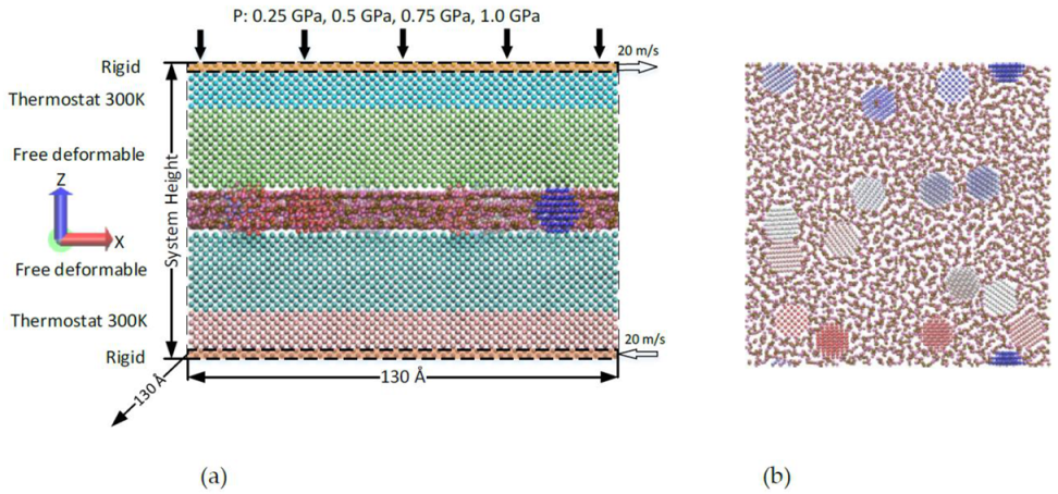
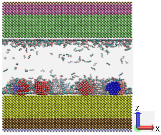
2.1. Materials and Model Setup

The MD simulation is performed through a large scale Atomic/Molecular Massively Parallel Simulator (LAMMPS) [41], which has been proven to be a very powerful MD simulator. As displayed in Figure 1, the geometry model consists of two <001> oriented BCC iron upper and lower walls, randomly distributed C4 molecules and 16 iron rigid nanoparticles with radius 8 Å, which leads to about 19% surface coverage by the nanoparticles. It should be noted that the use of iron for walls and nanoparticles is a simplification in this study. The iron wall is divided further into three regions: rigid region, thermostat region and free deformable region. Periodic boundary conditions have been defined along the X/Y lateral directions. In contrast, the Z normal direction is variable when the system height fluctuates; the system is compressed and sheared under 4 normal loads of 0.25, 0.5, 0.75 and 1.0 GPa. The lower and upper iron walls slide against each other with a velocity of 20 m/s in the X direction, which results in the lubricant shearing at 40 m/s. It should be stated that the relative motion velocity of 40 m/s is quite high compared to the practical applications and real experiments; however, it is mainly used in this study to model several sliding cycles within a reasonable simulation time. In the current investigation, different amounts of C4-alkane molecular are used to construct lubricant flow, which could provide a different lubricated condition, such as less or full lubrication.

2.2. Force Field

In this work, there might be a severe plastic deformation that intensively depends on the proper force field, which could not be handled correctly through simple potentials including the Morse and Lennard–Jones potentials. Therefore, the embedded-atom method (EAM) force field designed for solid Fe was used in this work [42].
U ( r i j ) = 4 ε σ r i j 12 σ r i j 6
σ ij = 1 2 σ ii + σ jj ε ij = ε ii ε jj
E bond = K b 2 r r 0 2
E bend = K θ 2 θ θ 0 2
E torsion = c 0 + c 1 1 + cos ( α ) + c 2 1 cos ( 2 α ) + c 3 1 + cos ( 3 α )
The C4-alkane is simulated by the TraPPE United Atom force field which utilizes pseudo-atoms to represent the CHx groups [43]. It should be noted that, TraPPE United Atom for field is not the best one to accurately describe the material properties compared to other advanced force fields, but it is still widely used from the consideration of computational efficiency [25,26,27,43,44,45]. Thus, we have applied the TraPPE United Atom force filed for atomistic simulations in order to reduce the computational cost, which is very important for NEMD simulations when there are a huge number of cases to run. The bond stretching of Ebond, angle bending of Ebend and torsion angle of Etorsion have been calculated by Equations (3)–(5), respectively. The Lennard–Jones potential is used to model the interactions between the segment-pairs that are separated by more than three bonds as displayed in Equation (1). The interactions between surface–particle, liquid–particle, and particle–particle are also calculated by LJ potential. The parameters of unlike interactions were calculated by the Lorentz–Berthelot combining laws; see Equation (2). All the TraPPE-UA and LJ potential parameters are listed in Table 1.

3. MD Simulation Procedures

The detailed model geometry has been introduced in the previous section. Each MD simulation is divided into three steps. The first step is dynamic relaxation with 200 ps. The atoms of both lower and upper rigid layers are constrained to maintain the system height, which allows these lubricant molecules to fully relax and the model to reach equilibrium with no variation in the energy of the system. In the second step, uniformly distributed loads of 0.25, 0.5, 0.75 and 1.0 GPa are added on the atoms belonging to the upper rigid layer. On the other hand, the atoms of the lower rigid layer are fixed along the normal direction, and therefore the lubricant is compressed. However, the rigid layers are limited within a maximum distance of 0.00025 Å every time step during the limited compression to achieve gentile touch between deformable layers and rigid particles. Within this stage, in order to maintain the temperature at 300 K, the Nose–Hoover thermostat [48] is applied on the atoms of thermostat layers with a damping coefficient of 100 fs. After the limited compression for 600 ps, the rigid layers are updated freely at each time step for the subsequent 200 ps. The last step is a sliding or shearing process. The atoms of upper rigid layer are sliding at a velocity of 20 m/s along the X direction for 3000 ps. The same sliding velocity is applied to the atoms of lower rigid layer but in an opposite direction, which results in the lower and upper walls sliding and lubricant shearing. During this step, the energy is dissipated via thermostat regions. In order to conduct the numerical integration of atomic classical equations of motions, the Velocity–Verlet algorithm is used in the present study, and the time step is set to 2 fs. The total simulation time was 4000 ps. For the post-processing of simulation data, both friction force and system height are saved every 4 ps, and a smooth window with size of 20 is used for figure plotting.

4. Results and Discussion

During the dynamic relaxation step, different numbers of C4-alkane from 500 to 4000 molecules are used as lubricants. Figure 2 exhibits a typical example that 1500 C4-alkane molecules and 16 rigid particles are fully relaxed during the first 200 ps. All the nanoparticles are close to the lower wall. This is because their initial positions are closer to the lower wall than those of the upper wall. For simplicity, flat model, particle model and lubricated model are used in the subsequent sections to present the model without nanoparticles and C4-alkane molecules, the model only lubricated with nanoparticles, and the model lubricated with a mixture of nanoparticles and C4-alkane molecules, respectively.

4.1. Dry Contact

Aiming to study the influence of nanoparticles during boundary friction, studies on the flat and particle models are conducted first. After relaxation, different normal loads varying from 0.25 to 1.0 GPa are applied on iron atoms of the upper rigid layer. Figure 3 indicates the system height evolution against the simulation time, and a comparison between the flat and nanoparticle models is performed. It is evident from the figure that there is no obvious system height change for the flat model under all normal loads. This is due to the high stiffness of pure Fe. During the subsequent sliding process, a slight fluctuation of system height is observed, which is due to the same surface structures of both upper and lower walls. In contrast, much more stable system heights are observed in the nanoparticle models when the normal load varies between 0.25 and 0.75 GPa. However, when the normal load is increased up to 1.0 GPa, there is an obvious drop in the system height. Moreover, the drop becomes more severe with the sliding distance, which indicates that plastic deformation may occur at the top surfaces of both upper and lower walls. More details will be discussed in the later section of this paper.
Although the system height predicted by the flat models in Figure 3 remains stable, the corresponding simulated friction force is relatively large and fluctuates dramatically during the sliding process. Figure 4a,b reveals the influence of normal load on the evolution history of friction force against the simulation time obtained in different simulation systems. For flat models (Figure 4a), the upper and lower surfaces contact directly. There is an unusual friction force change when the simulation time is increased from 250 to 500 ps, as marked by the red dashed circle in the figure. This phenomenon is mainly due to the alignment pattern between the upper and lower walls. Similar jump in the friction force was also observed by Stephan et al. [49], in which the simulated tangential force increased as the chip started to form at the beginning of the lateral movement. On the other hand, An and co-authors [50] have successfully proposed a quantitative relationship of the nanoscale friction force and coefficient between liquid and solid based on their atomic force microscopy experimental characterizations. To better illustrate this effect, a typical system slice along the vertical direction is shown in Figure 5. At 300 ps, the upper wall normally approaches the lower wall. Due to the repulsive force between two deformable layers, the force Fx is increased. However, the force decreases immediately when two surfaces have the shortest distance because the walls can move freely along both X and Y directions.
In comparison with the results shown in Figure 4a by flat models, the particle models predict much smaller friction forces as displayed in Figure 4b for all the studied normal loads. The wall blocks separating from each other are observed when the hard nanoparticles are added in the boundary friction system. This agrees well with the observations by Tao et al. [51] that nanoparticles are able to divide the rubbing planes and thereby avoid direct surface contact. Specifically, while the normal load is ≤0.75 GPa, the friction force drops nearly to zero. This is likely owing to the rolling effect of nanoparticles when the normal load is very low [39]. Figure 6 reveals that the rolling effect of nanoparticles helps to decrease the friction force. For the normal load of 0.25 GPa, the nanoparticles are supporting the upper surface against the normal load but also smoothly rolling between the surfaces during the sliding process. The shape of atoms in gray color remains unchanged through the whole sliding process, suggesting the absence of plastic deformation in the friction pairs. When the normal load rises to 1.0 GPa, there is an obvious rise in the friction force as can be seen from Figure 4b. It means that the nanoparticles induce the plastic deformation in the top surface and thus lead to the increase of friction force. This deformation is shown in Figure 7. It should be noted that no nanoparticles are shown in the figure for clearness. The atoms of the top surface are deformed to accommodate the rigid nanoparticles, which is to ensure the rolling effect between surfaces.
In order to gain a better understanding on the plastic deformation under boundary friction condition, particle models with different numbers of nanoparticles are also carried out in this study. Specifically, four cases with 4, 8, 12 and 16 nanoparticles placed between the friction surfaces are considered. Moreover, only the normal load of 1.0 GPa is applied in these cases to ensure that the nanoparticles are able to penetrate the wall blocks. Compared with the flat model, the addition of 4 nanoparticles results in a slight increase of system height, but it remains stable during sliding as can be seen from Figure 8. Although additions of 12 and 16 nanoparticles lead to almost the same system height during compression step, the system height of the model containing 12 nanoparticles drops more quickly once the sliding starts. It has been found that fewer nanoparticles share larger compression stress and thus penetrate deeper into the wall blocks. This phenomenon becomes more obvious when the model contains 8 nanoparticles. In order to understand the influence of the number of nanoparticles, the friction force obtained in the model containing 4, 8, 12 or 16 nanoparticles is plotted in Figure 9, respectively. A comparison clearly indicates that more nanoparticles ensure the rolling effect and further reduce the friction force.
Figure 10 shows the surface morphology of the lower wall after sliding process. It is evident that grooves form during friction, which indicates that there is a cutting action from nanoparticles on surfaces. Such kind of grooves or scratches formation on the worn surface has often been experimentally observed in either nanoscale or microscale [52,53]. It has to be mentioned that only atoms of the lower wall with Z > 25 Å are shown in Figure 10 to clearly demonstrate the cutting effect. The corresponding color bar indicates the Z position of the atoms of the lower wall. As displayed in Figure 10a, all 4 nanoparticles deeply penetrate into the wall blacks under the normal load of 1.0 GPa. In addition, the atoms next to nanoparticles tend to accumulate and act like a cutting tool to remove the materials during the sliding process. Very similar results are also found in the model with 8 nanoparticles, as displayed in Figure 10b. By increasing the number of nanoparticles to 12 and 16, more grooves are formed with smaller height difference at block surfaces, as can be seen from Figure 10c,d, respectively.

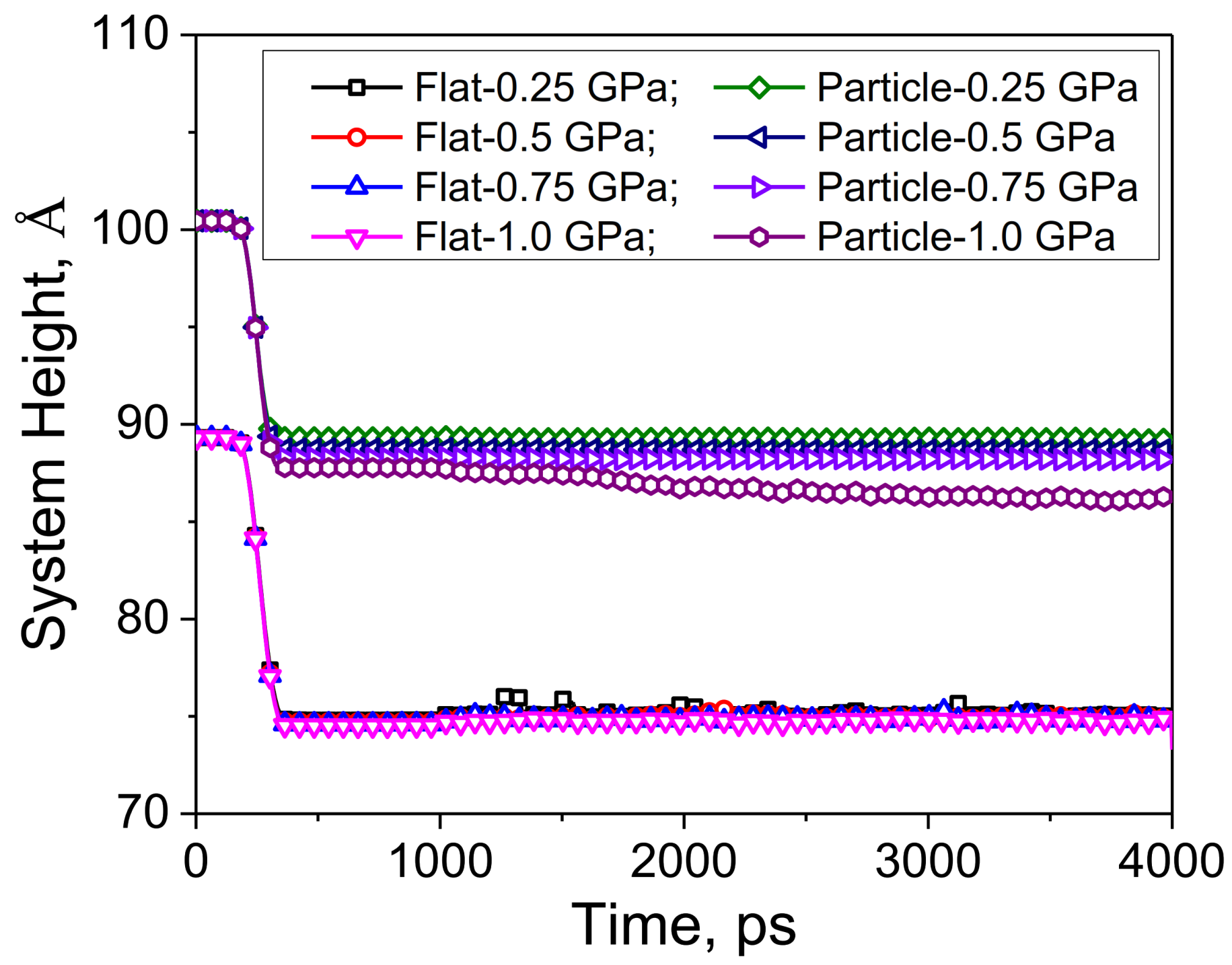
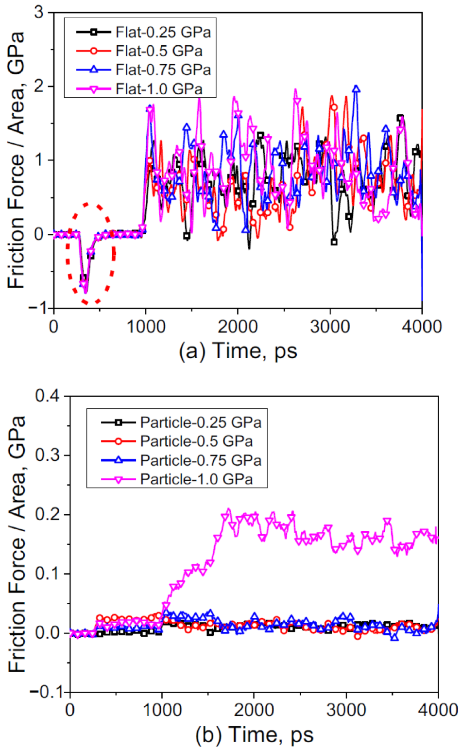
4.2. Lubricated Contact

When lubricant is present in the boundary friction system, the wall surfaces are subjected to a combined influence of nanoparticles, adhesion as well as the lubricant, particularly while the average thickness of the lubricant is comparable to the surface roughness and the size of nanoparticles [23]. In this section, MD simulations considering the C4-alkane as the lubricant are carried out to investigate its influence on the boundary friction.
Figure 11 displays the system height evolution for the lubricated models with C4-alkane and 16 nanoparticles. Each system has an initial system height, which is apparently dependent on the number of C4-alkane molecules. However, all systems have the same height reduction rate because of the limited distance movement at each time step. This step could ensure the gentile touch between two wall surfaces and nanoparticles. Before the sliding process, it is important to guarantee the initial contact surface. Otherwise, the sharp contact could result in severe indentation on the wall surface, remaining in the following sliding process. From Figure 11, it has been found that C4-alkane molecules less than 1000 are unable to support the upper wall as the height does not change compared with the particle model. However, 2000 molecules of C4-alkane start supporting against the normal load as the height increases. More obvious increases could be observed in the systems which have 3000 or 4000 molecules.
Similar to the system height evolution, the friction force also varies when the number of lubricant molecules changes. From the results shown in Figure 12, it can be found that C4-alkane with 500 and 1000 molecules has nearly no contributions as a lubricant to decrease the friction force. However, when the number of molecules is greater than 1500 or above, an obvious change in the friction force is visible. It is due to the flow of lubricant starting to support the upper wall against the normal load. Therefore, the particles are subjected to less compression. It seems that the surfaces are only lubricated by fluid, and similar results were also observed in our previous study [25]. It is worth noting that, in addition to the system height, the nanoparticle-surface indentation depth is also a very important parameter which makes it possible to link and compare the simulation and experimental results [54,55]. Such kind of analysis will be conducted in our future work, where a series of new NEMD simulations considering different types of nanoparticles with 3D rough surfaces will be developed.
To better explore the effect and mechanism of the lubricant fluid in the boundary lubrication system, the component of friction force corresponding to the systems having 500, 1000, 1500 and 2000 molecules is plotted in Figure 13, respectively. When the system only has 500 C4-alkane molecules mixed with nanoparticles, the supporting force is mainly contributed by the nanoparticles, as can be seen from Figure 13a. There is no direct supporting force from the lower wall as the gap distance is larger than the LJ cutoff distance. It is interesting that the force Z from C4-alkane decreases with the sliding process and even becomes negative after 1500 ps. It means that C4-alkane helps to compress the upper and lower walls. This is likely due to the large space formed by wall surfaces and nanoparticles. In addition, C4-alkane is free to flow and naturally the molecules tend to accumulate. The adsorption between C4-alkane and surfaces finally results in an attractive force between them. However, the negative force from C4-alkane disappears quickly when the flow is under compression or there is less space, which could be observed in Figure 13b. During the compression step and early stage of sliding, the supporting force from C4-alkane is near zero. It starts to increase at 2500 ps as the system height decreases slightly from then on. When 1500 molecules are mixed with nanoparticles, the force components remain stable during the sliding process. However, on the other hand, 2000 molecules exhibit a completely different influence on the supporting force. Figure 13d shows that nanoparticles exert an attractive force on wall surfaces, which results in a larger compression force on the lubricant flow. In this condition, nanoparticles could move freely within the lubricant flow. However, the nanoparticle atoms are still in the cut-off distance with surface atoms, which finally results in an attractive force. Therefore, these results reveal a great influence of the number of C4-alkane molecules on its lubricity within a boundary friction system and a transition from partial to full lubrication.

5. Conclusions

In the present study, a comprehensive NEMD simulation model considering two iron wall surfaces, mixed C4-alkane and nanoparticles as lubricant has been established to explore the influences of nanoparticles and fluid on the surface contact and friction force during boundary friction system. The simulation results revealed that nanoparticles were acting like ball bearings between contact surfaces, leading to a change from the sliding friction to rolling friction. When a large normal load greater than 0.75 GPa was applied, there was severe plastic deformation at the top surface. Moreover, C4-alkane with a number of molecules lower than 1500 was unable to support the upper wall, which had a similar friction behavior to that of the cases with only nanoparticles. In addition, there was an attractive force from C4-alkane molecules to surfaces, which resulted in an extra compression. This was due to the large space formed by wall surfaces and nanoparticles during the sliding process. However, with the increase of the number of molecules, the surfaces were gradually separated by the lubricant fluid from the mixed lubrication to totally thin film lubrication, and the friction force dropped dramatically.

Author Contributions

Conceptualization, X.Z. and L.S.; methodology, X.Z., L.S. and G.D.; software, X.Z., G.D. and J.Z.; validation, J.Z. and H.Z.; investigation, X.Z., L.S. and G.D.; resources, L.S. and A.K.T.; writing—original draft preparation, X.Z., L.S., G.D. and J.Z.; writing—review and editing, X.Z., L.S., H.Z. and A.K.T.; project administration, L.S.; funding acquisition, L.S. and A.K.T. All authors have read and agreed to the published version of the manuscript.

Funding

This research was funded by Australian Research Council (Grant Numbers: DE180100124, DP170103173 and DP190103455).

Data Availability Statement

Not applicable.

Acknowledgments

All authors appreciate very much for conducing simulations using a HPC cluster that belonged to the University of Wollongong and the computing facilities provided by NCI National Facility of Australia. L.S. is grateful to the Australian Research Council for awarding her the Discovery Early Career Researcher Award (DECRA) fellowship (DE180100124). G.D., H.Z. and K.T. would like to acknowledge the financial supports from the Australian Research Council (DP 170103173 and DP190103455).

Conflicts of Interest

The authors declare no conflict of interest.

References

  1. Zhou, J.; Wu, Z.; Zhang, Z.; Liu, W.; Xue, Q. Tribological behaviour and lubricating mechanism of Cu nanoparticles in oil. Tribol. Lett. 2000, 8, 213–218. [Google Scholar] [CrossRef]
  2. Qiu, S.; Zhou, Z.; Dong, J.; Chen, G. Preparation of Ni nanoparticles and evaluation of their tribological performance as potential antiwear additives in oils. J. Tribol. 2001, 123, 441–443. [Google Scholar] [CrossRef]
  3. Xue, Q.; Liu, W.; Zhang, Z. Friction and wear properties of a surface-modified TiO2 nanoparticle as an additive in liquid paraffin. Wear 1997, 213, 29–32. [Google Scholar] [CrossRef]
  4. Hu, Z.S.; Dong, J.X.; Chen, G.X. Study on antiwear and reducing friction additive of nanometer ferric oxide. Tribol. Int. 1998, 31, 355–360. [Google Scholar] [CrossRef]
  5. Radice, S.; Mischler, S. Effect of electrochemical and mechanical parameters on the lubrication behaviour of Al2O3 nanoparticles in aqueous suspensions. Wear 2006, 261, 1032–1041. [Google Scholar] [CrossRef]
  6. Gupta, B.K.; Bhushan, B. Fullerene particles as an additive to liquid lubricants and greases for low friction and wear. Lubr. Eng. 1994, 50, 524–528. [Google Scholar]
  7. Cizaire, L.; Vacher, B.; Le Mogne, T.; Martin, J.M.; Rapoport, L.; Margolin, A.; Tenne, R. Mechanisms of ultra-low friction by hollow inorganic fullerene-like MoS2 nanoparticles. Surf. Coat. Technol. 2002, 160, 282–287. [Google Scholar] [CrossRef]
  8. Rabaso, P.; Ville, F.; Dassenoy, F.; Diaby, M.; Afanasiev, P.; Cavoret, J.; Vacher, B.; Le Mogne, T. Boundary lubrication: Influence of the size and structure of inorganic fullerene-like MoS2 nanoparticles on friction and wear reduction. Wear 2014, 320, 161–178. [Google Scholar] [CrossRef]
  9. Tenne, R. Inorganic nanotubes and fullerene-like nanoparticles. Nat. Nanotechnol. 2006, 1, 103–111. [Google Scholar] [CrossRef] [PubMed]
  10. Lahouij, I.; Dassenoy, F.; Vacher, B.; Martin, J.M. Real time TEM imaging of compression and shear of single fullerene-like MoS2 nanoparticle. Tribol. Lett. 2011, 45, 131–141. [Google Scholar] [CrossRef]
  11. Dai, W.; Kheireddin, B.; Gao, H.; Liang, H. Roles of nanoparticles in oil lubrication. Tribol. Int. 2016, 102, 88–98. [Google Scholar] [CrossRef]
  12. Xie, H.; Jiang, B.; He, J.; Xia, X.; Pan, F. Lubrication performance of MoS2 and SiO2 nanoparticles as lubricant additives in magnesium alloy-steel contacts. Tribol. Int. 2016, 93, 63–70. [Google Scholar] [CrossRef]
  13. Moshkovith, A.; Perfiliev, V.; Lapsker, I.; Fleischer, N.; Tenne, R.; Rapoport, L. Friction of fullerene-like WS2 nanoparticles: Effect of agglomeration. Tribol. Lett. 2006, 24, 225–228. [Google Scholar] [CrossRef]
  14. Tevet, O.; Von-Huth, P.; Popovitz-Biro, R.; Rosentsveig, R.; Wagner, H.D.; Tenne, R. Friction mechanism of individual multilayered nanoparticles. Proc. Natl. Acad. Sci. USA 2011, 108, 19901–19906. [Google Scholar] [CrossRef] [Green Version]
  15. Šperka, P.; Křupka, I.; Hartl, M. Evidence of plug flow in rolling—sliding elastohydrodynamic contact. Tribol. Lett. 2014, 54, 151–160. [Google Scholar] [CrossRef]
  16. Ghaednia, H.; Babaei, H.; Jackson, R.L.; Bozack, M.J.; Khodadadi, J.M. The effect of nanoparticles on thin film elasto-hydrodynamic lubrication. Appl. Phys. Lett. 2013, 103, 263111. [Google Scholar] [CrossRef]
  17. Jackson, R.L.; Ghaednia, H.; Babaei, H.; Khodadadi, J.M. Comment on Sperka, P., I. Krupka, M. Hartl (2014). “evidence of plug flow in rolling—sliding elastohydrodynamic contact.” Tribology Letters 54(2): 151–160. Tribol. Lett. 2014, 56, 407. [Google Scholar] [CrossRef] [Green Version]
  18. Srivastava, I.; Kotia, A.; Ghosh, S.K.; Ali, M.K.A. Recent advances of molecular dynamics simulations in nanotribology. J. Mol. Liq. 2021, 335, 116154. [Google Scholar] [CrossRef]
  19. Zhang, J.; Su, L.; Wang, Z. Concurrent multiscale simulations of rough lubricated contact of aluminum single crystal. Metals 2020, 10, 965. [Google Scholar] [CrossRef]
  20. Stephan, S.; Lautenschlaeger, M.P.; Alhafez, I.A.; Horsch, M.T.; Urbassek, H.M.; Hasse, H. Molecular dynamics simulation study of mechanical effects of lubrication on a nanoscale contact process. Tribol. Lett. 2018, 66, 126. [Google Scholar] [CrossRef]
  21. Eder, S.; Vernes, A.; Vorlaufer, G.; Betz, G. Molecular dynamics simulations of mixed lubrication with smooth particle post-processing. J. Phys. Condens. Matter 2011, 23, 175004. [Google Scholar] [CrossRef]
  22. Jabbarzadeh, A.; Harrowell, P.; Tanner, R.I. Low friction lubrication between amorphous walls: Unraveling the contributions of surface roughness and in-plane disorder. J. Chem. Phys. 2006, 125, 034703. [Google Scholar] [CrossRef]
  23. Jabbarzadeh, A.; Atkinson, J.D.; Tanner, R.I. Effect of the wall roughness on slip and rheological properties of hexadecane in molecular dynamics simulation of Couette shear flow between two sinusoidal walls. Phys. Rev. E 2000, 61, 690–699. [Google Scholar] [CrossRef]
  24. Spijker, P.; Anciaux, G.; Molinari, J.F. Dry sliding contact between rough surfaces at the atomistic scale. Tribol. Lett. 2011, 44, 279–285. [Google Scholar] [CrossRef]
  25. Zheng, X.; Zhu, H.; Tieu, A.K.; Chen, K. Molecular dynamics simulation of confined n-alkanes: Ordered structure and crystalline bridges. Int. J. Surf. Sci. Eng. 2014, 8, 201–212. [Google Scholar] [CrossRef]
  26. Zheng, X.; Zhu, H.; Tieu, A.K.; Kosasih, B. A molecular dynamics simulation of 3D rough lubricated contact. Tribol. Int. 2013, 67, 217–221. [Google Scholar] [CrossRef]
  27. Zheng, X.; Zhu, H.; Tieu, A.K.; Kosasih, B. Roughness and lubricant effect on 3D atomic asperity contact. Tribol. Lett. 2013, 53, 215–223. [Google Scholar] [CrossRef]
  28. Ewen, J.P.; Heyes, D.M.; Dini, D. Advances in nonequilibrium molecular dynamics simulations of lubricants and additives. Friction 2018, 6, 349–386. [Google Scholar] [CrossRef] [Green Version]
  29. Lee, W.G.; Cho, K.H.; Jang, H. Molecular dynamics simulation of rolling friction using nanosize spheres. Tribol. Lett. 2009, 33, 37–43. [Google Scholar] [CrossRef]
  30. Joly-Pottuz, L.; Bucholz, E.W.; Matsumoto, N.; Phillpot, S.R.; Sinnott, S.B.; Ohmae, N.; Martin, J.M. Friction properties of carbon nano-onions from experiment and computer simulations. Tribol. Lett. 2010, 37, 75–81. [Google Scholar] [CrossRef]
  31. Bucholz, E.W.; Phillpot, S.R.; Sinnott, S.B. Molecular dynamics investigation of the lubrication mechanism of carbon nano-onions. Comput. Mater. Sci. 2012, 54, 91–96. [Google Scholar] [CrossRef]
  32. Eder, S.J.; Feldbauer, G.; Bianchi, D.; Cihak-Bayr, U.; Betz, G.; Vernes, A. Applicability of macroscopic wear and friction laws on the atomic length scale. Phys. Rev. Lett. 2015, 115, 025502. [Google Scholar] [CrossRef]
  33. Ewen, J.P.; Gattinoni, C.; Thakkar, F.M.; Morgan, N.; Spikes, H.A.; Dini, D. Nonequilibrium molecular dynamics investigation of the reduction in friction and wear by carbon nanoparticles between iron surfaces. Tribol. Lett. 2016, 63, 38. [Google Scholar] [CrossRef]
  34. Shi, J.; Fang, L.; Sun, K. Friction and wear reduction via tuning nanoparticle shape under low humidity conditions: A nonequilibrium molecular dynamics simulation. Comput. Mater. Sci. 2018, 154, 499–507. [Google Scholar] [CrossRef]
  35. Su, L.; Krim, J.; Brenner, D.W. Dynamics of Neutral and charged nanodiamonds in aqueous media confined between gold surfaces under normal and shear loading. ACS Omega 2020, 5, 10349–10358. [Google Scholar] [CrossRef] [PubMed]
  36. Lv, J.; Bai, M.; Cui, W.; Li, X. The molecular dynamic simulation on impact and friction characters of nanofluids with many nanoparticles system. Nanoscale Res. Lett. 2011, 6, 200. [Google Scholar] [CrossRef] [PubMed] [Green Version]
  37. Ji, C.; Sun, S.; Wang, B.; Lin, B. Molecular dynamic simulations of the roles of nanoparticles in sliding friction process. Chem. Phys. Lett. 2019, 728, 44–49. [Google Scholar] [CrossRef]
  38. Hu, C.; Bai, M.; Lv, J.; Wang, P.; Li, X. Molecular dynamics simulation on the friction properties of nanofluids confined by idealized surfaces. Tribol. Int. 2014, 78, 152–159. [Google Scholar] [CrossRef]
  39. Hu, C.Z.; Bai, M.L.; Lv, J.Z.; Kou, Z.H.; Li, X.J. Molecular dynamics simulation on the tribology properties of two hard nanoparticles (diamond and silicon dioxide) confined by two iron blocks. Tribol. Int. 2015, 90, 297–305. [Google Scholar] [CrossRef]
  40. Persson, B.N.J.; Samoilov, V.N.; Zilberman, S.; Nitzan, A. Phenomenology of squeezing and sliding of molecularly thin Xe, CH4 and C16H34 lubrication films between smooth and rough curved solid surfaces with long-range elasticity. J. Chem. Phys. 2002, 117, 3897–3914. [Google Scholar] [CrossRef] [Green Version]
  41. Plimpton, S. Fast parallel algorithms for short-range molecular dynamics. J. Comput. Phys. 1995, 117, 1–19. [Google Scholar] [CrossRef] [Green Version]
  42. Mendelev, M.I.; Han, S.; Srolovitz, D.J.; Ackland, G.J.; Sun, D.Y.; Asta, M. Development of new interaction potentials appropriate for crystalline and liquid iron. Phil. Mag. 2003, 83, 3977–3994. [Google Scholar] [CrossRef]
  43. Martin, M.G.; Siepmann, J.I. Transferable potentials for phase equilibria. 1. United-atom description of n-alkanes. J. Phys. Chem. B 1998, 102, 2569–2577. [Google Scholar] [CrossRef]
  44. Eggimann, B.L.; Sun, Y.; Dejaco, R.F.; Singh, R.; Ahsan, M.; Josephson, T.R.; Siepmann, J.I. Assessing the quality of molecular simulations for vapor—liquid equilibria: An analysis of the TraPPE database. J. Chem. Eng. Data 2020, 65, 1330–1344. [Google Scholar] [CrossRef]
  45. Transferable Potentials for Phase Equilibria. Available online: http://trappe.oit.umn.edu/stretch.html (accessed on 15 September 2021).
  46. Savio, D.; Fillot, N.; Vergne, P.; Zaccheddu, M. A model for wall slip prediction of confined n-alkanes: Effect of wall-fluid interaction versus fluid resistance. Tribol. Lett. 2012, 46, 11–22. [Google Scholar] [CrossRef]
  47. Kalyanasundaram, V.; Spearot, D.E.; Malshe, A.P. Molecular dynamics simulation of nanoconfinement induced organization of w-Decane. Langmuir 2009, 25, 7553–7560. [Google Scholar] [CrossRef]
  48. Evans, D.J.; Holian, B.L. The nose—hoover thermostat. J. Chem. Phys. 1985, 83, 4069. [Google Scholar] [CrossRef]
  49. Stephan, S.; Dyga, M.; Urbassek, H.M.; Hasse, H. The influence of lubrication and the solid—fluid interaction on thermodynamic properties in a nanoscopic scratching process. Langmuir 2019, 35, 16948–16960. [Google Scholar] [CrossRef] [PubMed]
  50. An, R.; Huang, L.; Long, Y.; Kalanyan, B.; Lu, X.; Gubbins, K.E. Liquid—solid nanofriction and interfacial wetting. Langmuir 2016, 32, 743–750. [Google Scholar] [CrossRef] [PubMed]
  51. Tao, X.; Zhao, J.Z.; Xu, K. The ball-bearing effect of diamond nanoparticles as an oil additive. J. Phys. D Appl. Phys. 1996, 29, 2932–2937. [Google Scholar] [CrossRef]
  52. Peng, D.X.; Chen, C.H.; Kang, Y.; Chang, Y.P.; Chang, S.Y. Size effects of SiO2 nanoparticles as oil additives on tribology of lubricant. Ind. Lubr. Tribol. 2010, 62, 111–120. [Google Scholar] [CrossRef]
  53. Sia, S.Y.; Sarhan, A.A.D. Morphology investigation of worn bearing surfaces using SiO2 nanolubrication system. Int. J. Adv. Manuf. Technol. 2014, 70, 1063–1071. [Google Scholar] [CrossRef]
  54. Bowden, F.P.; Tabor, D. Friction, lubrication and wear: A survey of work during the last decade. Br. J. Appl. Phys. 1966, 17, 1521–1544. [Google Scholar] [CrossRef]
  55. Gao, Y.; Brodyanski, A.; Kopnarski, M.; Urbassek, H.M. Nanoscratching of iron: A molecular dynamics study of the influence of surface orientation and scratching direction. Comput. Mater. Sci. 2015, 103, 77–89. [Google Scholar] [CrossRef]
Figure 1. (a) A typical molecular structure showing C4-alkane and 16 nanoparticles were confined between the iron walls and (b) top view of nanoparticles and C4-alkane fluid. Normal load (P) is only applied on the upper rigid region, but the lower rigid region is fixed in the Z direction. These white arrows exhibit the sliding direction at a speed of 20 ms/s imposed on rigid regions.
Metals 11 01464 g001
Figure 2. Lubricated model with 1500 C4-alkane molecules in the relaxation step.
Metals 11 01464 g002
Figure 3. Comparison of the system height evolution history against the simulation time under various normal loads between the flat and particle models.
Metals 11 01464 g003
Figure 4. The friction force evolution history when normal load is increased from 0.25 to 1.0 GPa in the (a) flat and (b) particle models.
Metals 11 01464 g004
Figure 5. The typical system slices (70 Å < x < 80 Å) at the moment of 300 and 400 ps. The unusual force Fx is due to the change of the upper and lower walls from initial mismatch pattern to match pattern.
Metals 11 01464 g005
Figure 6. Snapshots of particle models under 0.25 GPa at the moment of 1800, 1900 and 2000 ps. Only the lower wall and one typical particle are shown. Atoms in the particle are colored by their Z position to demonstrate the rolling effect. Atoms in Gray are in the slice from 100 Å to 120 Å along the X direction. The red arrow indicates the slice movement.
Metals 11 01464 g006
Figure 7. A side view of the particle model with 16 nanoparticles under the normal load of 1.0 GPa during sliding at 4000 ps. Only the upper and lower walls are shown to illustrate the plastic deformation during the sliding process.
Metals 11 01464 g007
Figure 8. Comparison of the evolution of system heights against the simulation time between the flat model and particle models containing 4, 8, 12 and 16 nanoparticles.
Metals 11 01464 g008
Figure 9. Comparison of the evolution of friction force against the simulation time between the flat model and particle models containing 4, 8, 12 and 16 nanoparticles.
Metals 11 01464 g009
Figure 10. The surface morphology of the lower wall with (a) 4, (b) 8, (c) 12 and (d) 16 nanoparticles at 4000 ps. Only the atoms of the lower wall with Z > 25 Å are shown and colored. The normal load applied in the boundary friction system is 1.0 GPa.
Metals 11 01464 g010
Figure 11. Comparison of the system height evolution history against the simulation time between the particle and lubricated models under the normal load of 1.0 GPa. The number of C4-alkane molecules varies from 500 to 4000.
Metals 11 01464 g011
Figure 12. Comparison of the friction force evolution history against the simulation time between the particle and lubricated models under the normal load of 1.0 GPa. The number of C4-alkane molecules varies from 500 to 4000.
Metals 11 01464 g012
Figure 13. Influence of the number of C4-alkane molecules on the total force Z and its component from flow, nanoparticles and the lower wall: (a) 500, (b) 1000, (c) 1500 and (d) 2000 molecules.
Metals 11 01464 g013
Table 1. The corresponding potential parameters used for alkane and Fe in this study [43,46,47].
LJ 12-6 Potentialsσ (Å)ε(eV)Mass (g/mol)
CH33.750.00844415.0351
CH23.950.00396314.0272
CH4.680.00086113.0191
Fe * [46]2.3210.0204555.8450
BondKb (eV/ Å2)r0 (Å)
C-C [47]39.02794641.54
AngleKθ (eV/rad2)θ0 (degrees)
C-C-C5.3858393114
Dihedralc0 (eV)c1 (eV)c2(eV)c3 (eV)
C-C-C-C00.030594−0.0058760.068190
* —LJ parameters of Fe are for surface–particle, liquid–particle and particle–particle interactions.
Publisher’s Note: MDPI stays neutral with regard to jurisdictional claims in published maps and institutional affiliations.

