
Characteristics of Microstructure Evolution during FAST Joining of the Tungsten Foil Laminate

 , , ,
, , ,  , and
, and 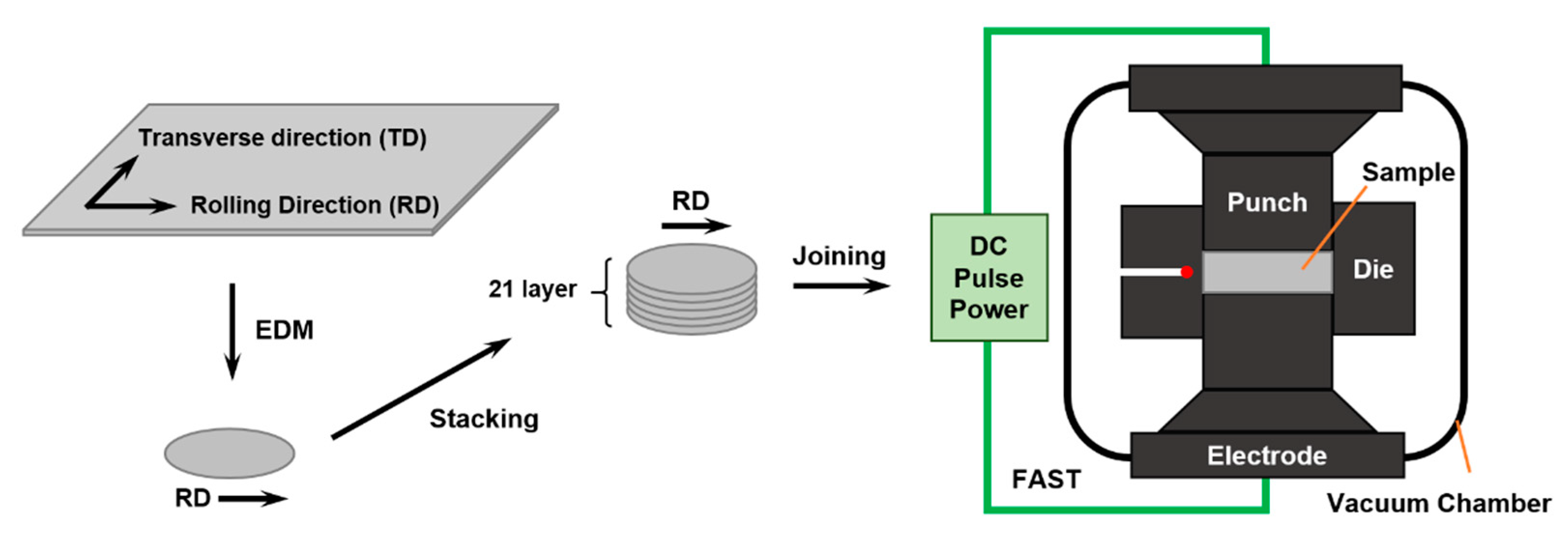
Abstract
:1. Introduction
2. Materials and Methods
2.1. Sample Preparation
2.2. Characterization
3. Results
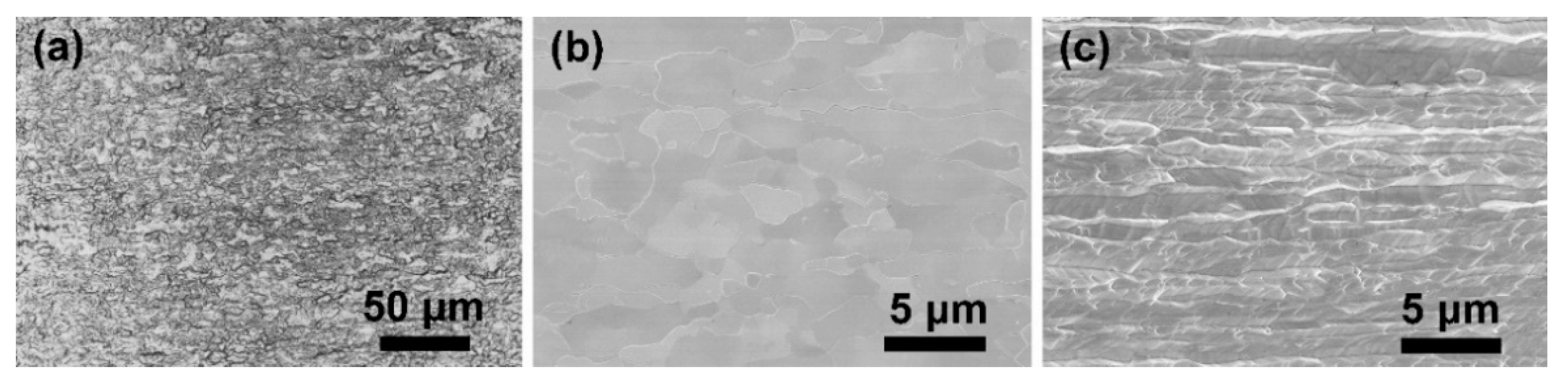
3.1. Microstructure of the Original W Foil
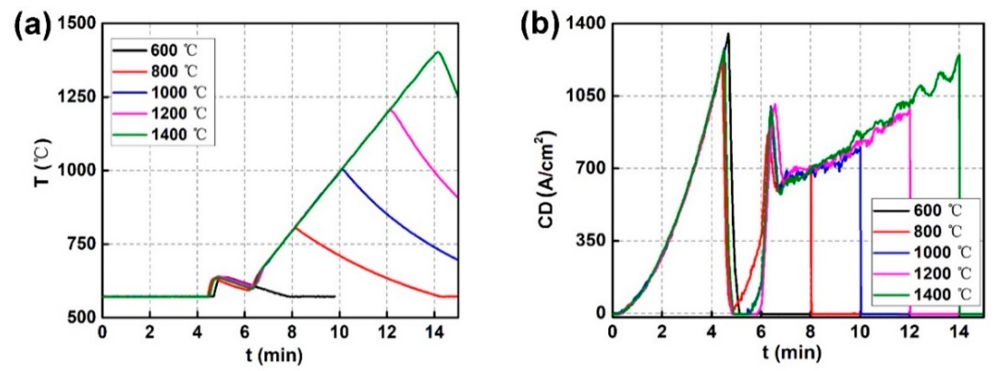
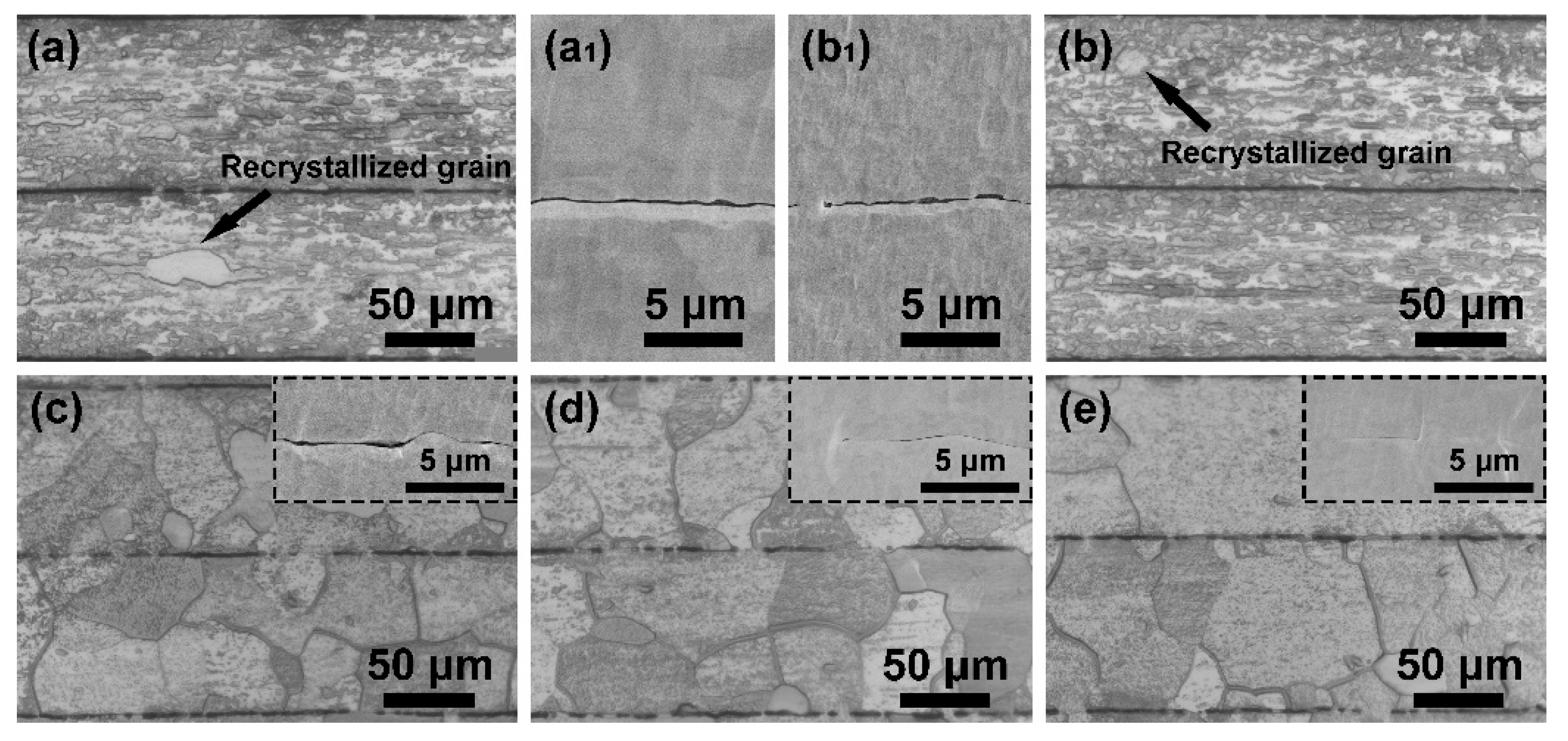
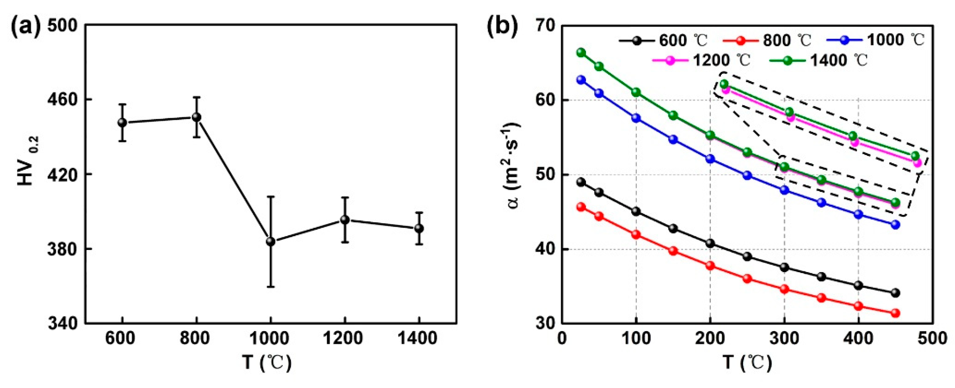
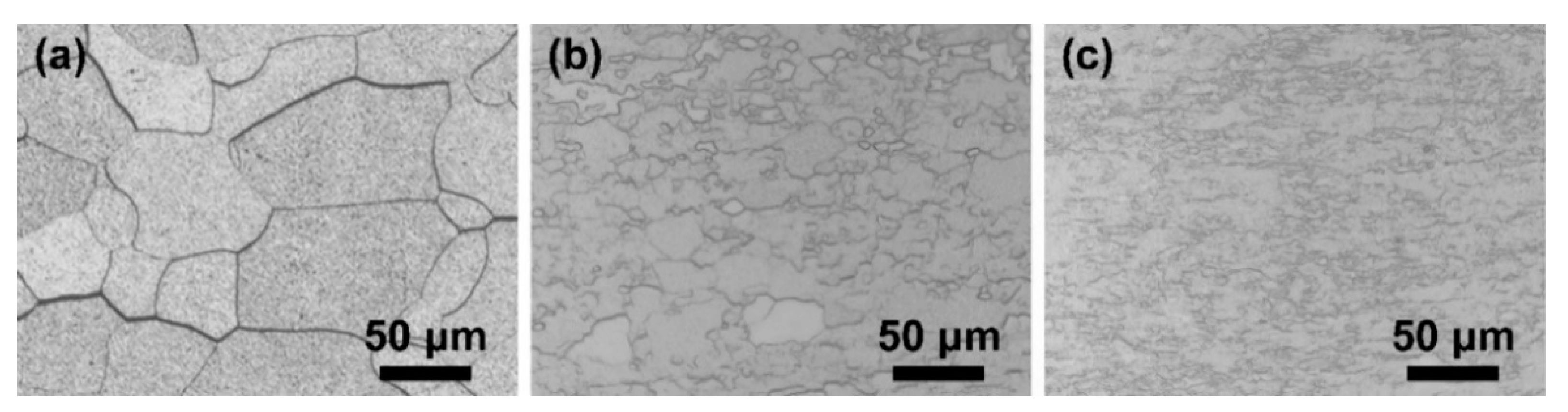
3.2. Joining Temperature Optimization
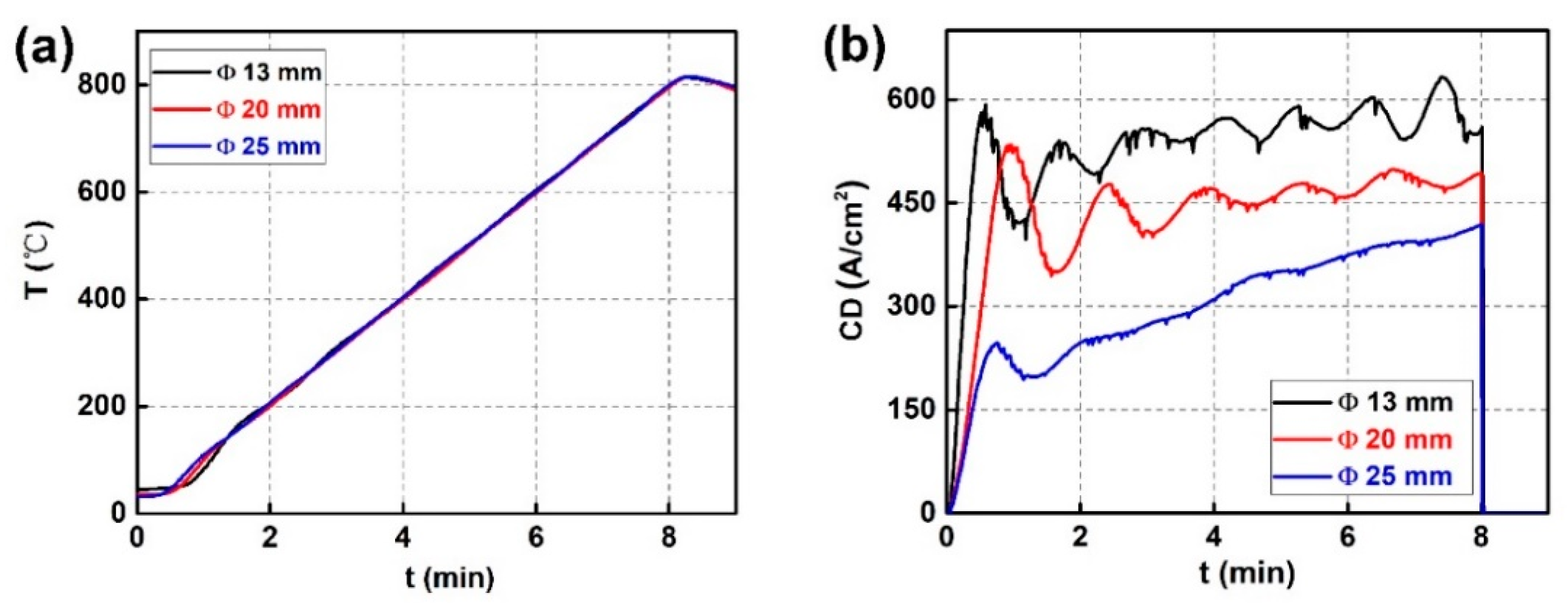
3.3. Current Density Optimization
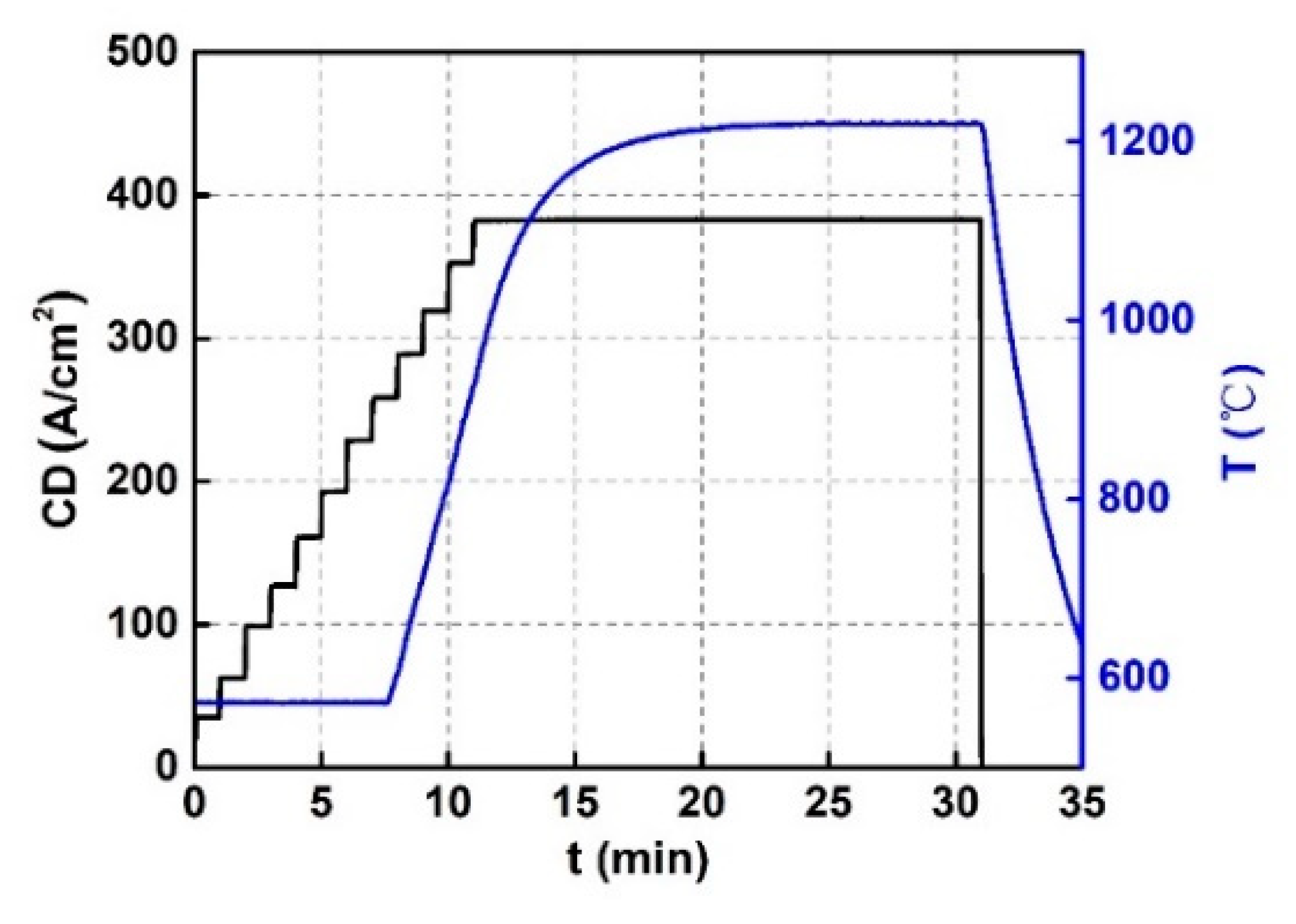
3.4. FAST Joining Optimization
4. Discussion
4.1. FAST Operation Conditions
4.2. Critical Electric Current
5. Summary and Outlook
Author Contributions
Funding
Data Availability Statement
Conflicts of Interest
References
- Huang, L.; Jiang, L.; Topping, T.D.; Dai, C.; Wang, X.; Carpenter, R.; Haines, C.; Schoenung, J.M. In situ oxide dispersion strengthened tungsten alloys with high compressive strength and high strain-to-failure. Acta Mater. 2017, 122, 19–31. [Google Scholar] [CrossRef]
- Butler, B.G.; Paramore, J.D.; Ligda, J.P.; Ren, C.; Fang, Z.Z.; Middlemas, S.C.; Hemker, K.J. Mechanisms of deformation and ductility in tungsten—A review. Int. J. Refract. Met. Hard Mater. 2018, 75, 248–261. [Google Scholar] [CrossRef]
- Yoshida, N. Review of recent works in development and evaluation of high-Z plasma facing materials. J. Nucl. Mater. 1999, 266–269, 197–206. [Google Scholar] [CrossRef]
- Tan, X.Y.; Li, P.; Luo, L.M.; Xu, Q.; Tokunaga, K.; Zan, X.; Wu, Y.C. Effect of second-phase particles on the properties of W-based materials under high-heat loading. Nucl. Mater. Energy 2016, 9, 399–404. [Google Scholar] [CrossRef] [Green Version]
- Mao, Y.; Coenen, J.W.; Riesch, J.; Sistla, S.; Almanstötter, J.; Reiser, J.; Terra, A.; Chen, C.; Wu, Y.; Raumann, L.; et al. Fracture behavior of random distributed short tungsten fiber-reinforced tungsten composite. Nucl. Fusion 2019, 58, 086034. [Google Scholar] [CrossRef]
- Chen, C.; Qian, S.F.; Liu, R.; Wang, S.; Liao, B.; Zhong, Z.H.; Cao, L.F.; Coenen, J.W.; Wu, Y.C. The microstructure and tensile properties of W/Ti multilayer composites prepared by spark plasma sintering. J. Alloys Compd. 2019, 780, 116–130. [Google Scholar] [CrossRef]
- Zhang, X.X.; Yan, Q.Z.; Yang, C.T.; Wang, T.N.; Ge, C.C. Microstructure, mechanical properties and bonding characteristic of deformed tungsten. Int. J. Refract. Met. Hard Mater. 2014, 43, 302–308. [Google Scholar] [CrossRef]
- Wu, Y.C. The routes and mechanism of plasma facing tungsten materials to improve ductility. Acta Metall. Sin. 2019, 55, 171–180. [Google Scholar]
- Vladica, N.; Stefan, W.; Daniel, F.; Reinhard, P. Fracture toughness evaluation of UFG tungsten foil. Int. J. Refract. Met. Hard Mater. 2018, 76, 214–225. [Google Scholar]
- Ritchie, R.O. The conflicts between strength and toughness. Nat. Mater. 2011, 10, 817–822. [Google Scholar] [CrossRef]
- Bermejo, R.; Danzer, R. High failure resistance layered ceramics using crack bifurcation and interface delamination as reinforcement mechanisms. Eng. Fract. Mech. 2010, 77, 2126–2135. [Google Scholar] [CrossRef]
- Bloyer, D.R.; Ritchie, R.O.; Venkateswara, R. Fracture toughness and R-curve behavior of laminated brittle-matrix composites. Metall. Mater. Trans. A 1998, 29, 2483–2496. [Google Scholar] [CrossRef]
- Liu, J.Q.; Chen, X.; Tan, X.Y.; Wang, W.J.; Wu, M.; Luo, L.M.; Zhu, X.Y.; Wu, Y.C. Toughening mechanism and research status of tungsten layered materials. Chin. J. Nonferrous Met. 2020, 30, 2331–2339. [Google Scholar]
- Reiser, J.; Franke, P.; Weingäertner, T.; Hoffmann, J.; Hoffmann, A.; Rieth, M. Tungsten laminates made of ultrafine-grained (UFG) tungsten foil—Ageing of tungsten-titanium (W-Ti) laminates. Int. J. Refract. Met. Hard Mater. 2015, 51, 264–274. [Google Scholar] [CrossRef]
- Yan, Z.; Xu, G.; Suo, J. Effect of transition layer on properties of Tungsten-Tantalum (W-Ta) laminated composite. Metals 2020, 10, 588. [Google Scholar] [CrossRef]
- Nogami, S.; Hazama, T.; Noto, H.; Nagasaka, T.; Hasegawa, A. Laminated composites using potassium doped tungsten. Fusion Eng. Des. 2020, 161, 111894. [Google Scholar] [CrossRef]
- Reiser, J.; Garrison, L.; Greuner, H.; Hoffmann, J.; Weingärtner, T.; Jäntsch, U.; Klimenkov, M.; Franke, P.; Bonk, S.; Bonnekoh, C.; et al. Ductilisation of tungsten (W): Tungsten laminated composites. Int. J. Refract. Met. Hard Mater. 2017, 69, 66–109. [Google Scholar] [CrossRef]
- Reiser, J.; Rieth, M.; Dafferner, B.; Hoffmann, A.; Yi, X.O.; Armstrong, D.E.J. Tungsten foil laminate for structural divertor applications—Analyses and characterisation of tungsten foil. J. Nucl. Mater. 2012, 424, 197–203. [Google Scholar] [CrossRef]
- Galatanu, A.; Galatanu, M.; Enculescu, M.; Reiser, J.; Sickinger, S. Thermophysical and mechanical properties of W-Cu laminates produced by FAST joining. Fusion Eng. Des. 2019, 146, 2371–2374. [Google Scholar] [CrossRef]
- Wu, Y.C. Manufacturing of tungsten and tungsten composite for fusion application via different routes. Tungsten 2019, 1, 80–90. [Google Scholar] [CrossRef] [Green Version]
- Park, J.W.; Jeong, H.J.; Jin, S.W.; Kim, M.J.; Lee, K.; Kim, J.J.; Hong, S.T.; Han, H.N. Effect of electric current on recrystallization kinetics in interstitial free steel and AZ31 magnesium alloy. Mater. Character. 2017, 133, 70–76. [Google Scholar] [CrossRef]
- Deng, S.H.; Yuan, T.C.; Li, R.D.; Zhang, M.; Xie, S.Y.; Wang, M.B.; Li, L.B.; Yuan, J.W.; Weng, Q.G. Influence of electric current on interdiffusion kinetics of W-Ti system during spark plasma sintering. Int. J. Refract. Met. Hard Mater. 2018, 75, 184–190. [Google Scholar] [CrossRef]
- Deng, S.H.; Li, R.D.; Yuan, T.C.; Xie, S.Y.; Zhang, M.; Zhou, K.C.; Cao, P. Direct current enhanced densification kinetics during spark plasma sintering of tungsten powder. Scr. Mater. 2018, 143, 25–29. [Google Scholar] [CrossRef]
- Liang, C.L.; Lin, K.L. The microstructure and property variations of metals induced by electric current treatment: A review. Mater. Charact. 2018, 145, 545–555. [Google Scholar] [CrossRef]
- Zhou, Y.F.; Zhao, Z.Y.; Tan, X.Y.; Luo, L.M.; Xu, X.; Zan, X.; Xu, Q.; Tokunaga, K.; Zhu, X.Y.; Wu, Y.C. Densification and microstructure evolution of W-TiC-Y2O3 during spark plasma sintering. Int. J. Refract. Met. Hard Mater. 2019, 79, 95–101. [Google Scholar] [CrossRef]
- Wang, W.J.; Tan, X.Y.; Liu, J.Q.; Chen, X.; Wu, M.; Luo, L.M.; Zhu, X.Y.; Chen, H.Y.; Mao, Y.R.; Litnovsky, A.; et al. The influence of heating rate on W-Cr-Zr alloy densification process and microstructure evolution during spark plasma sintering. Powder Technol. 2019, 370, 9–18. [Google Scholar] [CrossRef]
- Yang, S.P.; Wang, W.J.; Tan, X.Y.; Zhu, H.J.; Litnovsky, A.; Klein, F.; Mao, Y.R.; Coenen, J.W.; Linsmeier, C.; Luo, L.M.; et al. Influence of the applied pressure on the microstructure evolution of W-Cr-Y-Zr alloys during the FAST process. Fusion Eng. Des. 2021. [Google Scholar] [CrossRef]
- Hu, Z.Y.; Zhang, Z.H.; Cheng, X.W.; Wang, F.C.; Zhang, Y.F.; Li, S.L. A review of multi-physical fields induced phenomena and effects in spark plasma sintering: Fundamentals and applications. Mater. Des. 2020, 191, 108662. [Google Scholar]
- Cho, K.S.; Sim, H.S.; Kim, J.H.; Choi, J.H.; Lee, K.B.; Yang, H.R.; Kwon, H. A novel etchant for revealing the prior austenite grain boundaries and matrix information in high alloy steels. Mater. Charact. 2008, 59, 786–793. [Google Scholar] [CrossRef]
- Umberto, M.C.; Angela, T.; Chloé, D.; Wolfgang, P. Recovery and recrystallization kinetics of differently rolled, thin tungsten plates in the temperature range from 1325 °C to 1400 °C. Nucl. Mater. Energy 2019, 20, 100701. [Google Scholar]
- Umberto, M.C.; Wolfgang, P. Stagnant recrystallization in warm-rolled tungsten in the temperature range from 1150 °C to 1300 °C. Fusion Eng. Des. 2019, 146, 814–817. [Google Scholar]
- Vincent, C.; Silvain, J.F.; Heintz, J.M.; Chandra, N. Effect of porosity on the thermal conductivity of copper processed by powder metallurgy. J. Phys. Chem. Solids 2012, 73, 499–504. [Google Scholar] [CrossRef]
- Rollett, A.; Humphreys, F.; Rohrer, G.S.; Hatherly, M. Recrystallization and Related Annealing Phenomena, 2nd ed.; Pergamon: Oxford, UK, 2004. [Google Scholar]
- Alaneme, K.K.; Okotete, E.A. Recrystallization mechanisms and microstructure development in emerging metallic materials: A review. J. Sci. Adv. Mater. Dev. 2009, 4, 19–33. [Google Scholar] [CrossRef]


Publisher’s Note: MDPI stays neutral with regard to jurisdictional claims in published maps and institutional affiliations. |
© 2021 by the authors. Licensee MDPI, Basel, Switzerland. This article is an open access article distributed under the terms and conditions of the Creative Commons Attribution (CC BY) license (https://creativecommons.org/licenses/by/4.0/).
Share and Cite
Tan, X.; Wang, W.; Chen, X.; Mao, Y.; Litnovsky, A.; Klein, F.; Bittner, P.; Coenen, J.W.; Linsmeier, C.; Liu, J.; et al. Characteristics of Microstructure Evolution during FAST Joining of the Tungsten Foil Laminate. Metals 2021, 11, 886. https://doi.org/10.3390/met11060886
Tan X, Wang W, Chen X, Mao Y, Litnovsky A, Klein F, Bittner P, Coenen JW, Linsmeier C, Liu J, et al. Characteristics of Microstructure Evolution during FAST Joining of the Tungsten Foil Laminate. Metals. 2021; 11(6):886. https://doi.org/10.3390/met11060886
Chicago/Turabian StyleTan, Xiaoyue, Wujie Wang, Xiang Chen, Yiran Mao, Andrey Litnovsky, Felix Klein, Pawel Bittner, Jan Willem Coenen, Christian Linsmeier, Jiaqin Liu, and et al. 2021. "Characteristics of Microstructure Evolution during FAST Joining of the Tungsten Foil Laminate" Metals 11, no. 6: 886. https://doi.org/10.3390/met11060886